EP2333281A2 - Systeme und Verfahren zur unverdrosselten Steuerung von Gasturbinen-Kraftstoff-Steuerventilen - Google Patents
Systeme und Verfahren zur unverdrosselten Steuerung von Gasturbinen-Kraftstoff-Steuerventilen Download PDFInfo
- Publication number
- EP2333281A2 EP2333281A2 EP10191345A EP10191345A EP2333281A2 EP 2333281 A2 EP2333281 A2 EP 2333281A2 EP 10191345 A EP10191345 A EP 10191345A EP 10191345 A EP10191345 A EP 10191345A EP 2333281 A2 EP2333281 A2 EP 2333281A2
- Authority
- EP
- European Patent Office
- Prior art keywords
- valve
- gas
- flow
- factor
- fuel
- Prior art date
- Legal status (The legal status is an assumption and is not a legal conclusion. Google has not performed a legal analysis and makes no representation as to the accuracy of the status listed.)
- Granted
Links
Images


Classifications
-
- F—MECHANICAL ENGINEERING; LIGHTING; HEATING; WEAPONS; BLASTING
- F02—COMBUSTION ENGINES; HOT-GAS OR COMBUSTION-PRODUCT ENGINE PLANTS
- F02C—GAS-TURBINE PLANTS; AIR INTAKES FOR JET-PROPULSION PLANTS; CONTROLLING FUEL SUPPLY IN AIR-BREATHING JET-PROPULSION PLANTS
- F02C7/00—Features, components parts, details or accessories, not provided for in, or of interest apart form groups F02C1/00 - F02C6/00; Air intakes for jet-propulsion plants
- F02C7/22—Fuel supply systems
- F02C7/232—Fuel valves; Draining valves or systems
-
- F—MECHANICAL ENGINEERING; LIGHTING; HEATING; WEAPONS; BLASTING
- F02—COMBUSTION ENGINES; HOT-GAS OR COMBUSTION-PRODUCT ENGINE PLANTS
- F02C—GAS-TURBINE PLANTS; AIR INTAKES FOR JET-PROPULSION PLANTS; CONTROLLING FUEL SUPPLY IN AIR-BREATHING JET-PROPULSION PLANTS
- F02C9/00—Controlling gas-turbine plants; Controlling fuel supply in air- breathing jet-propulsion plants
- F02C9/16—Control of working fluid flow
- F02C9/24—Control of the pressure level in closed cycles
-
- F—MECHANICAL ENGINEERING; LIGHTING; HEATING; WEAPONS; BLASTING
- F02—COMBUSTION ENGINES; HOT-GAS OR COMBUSTION-PRODUCT ENGINE PLANTS
- F02C—GAS-TURBINE PLANTS; AIR INTAKES FOR JET-PROPULSION PLANTS; CONTROLLING FUEL SUPPLY IN AIR-BREATHING JET-PROPULSION PLANTS
- F02C9/00—Controlling gas-turbine plants; Controlling fuel supply in air- breathing jet-propulsion plants
- F02C9/26—Control of fuel supply
- F02C9/32—Control of fuel supply characterised by throttling of fuel
Definitions
- This invention generally relates to gas turbines, and more specifically to systems and methods for unchoked control of gas turbine fuel control valves.
- Gas turbines and other fuel consuming machines typically convert fuel energy into work, and the work may be used to drive an electrical generator, for example.
- the amount of work produced is dependent upon the fuel consumption rate and control valves are typically utilized to set the rate of fuel delivery to the combustion portion of the machine.
- a gas flow control valve may be electronically or manually controlled to increase or decrease the fuel flow rate to a combustor in an attempt to meet the load demand of the machine.
- the fuel throughput may be limited, and thus the work throughput of the machine may be limited.
- the turbine fuel supply system pressure may drop requiring a gas flow control valve to open significantly to satisfy the flow rate demand.
- the gas flow control valve may operate in an "un-choked” state, meaning that the fuel delivery rate is sensitive to changes in upstream fuel supply pressure as well as downstream valve outlet conditions.
- Conventional turbine systems typically operate in a “choked” state because downstream pressure changes due to changes in turbine cycle conditions, or changes in combustor pressure for example, can cause corresponding fuel rate spikes or oscillations.
- This method of operation is desirable for disturbance rejection so that transients in the upstream (fuel source) pressure and downstream (combustor) pressure cannot interrupt the steady flow of fuel to the turbine.
- Certain embodiments of the invention may include systems and methods for unchoked control of gas turbine fuel control valves
- a method for active control of a gas flow control valve.
- the method may include receiving a desired fuel command and an inlet pressure parameter, determining a gas flow gain based at least in part on the inlet pressure parameter, determining a valve flow coefficient based at least in part on the desired fuel command and the gas flow gain, and controlling the gas flow control valve based at least in part on the valve flow coefficient.
- another method for active control of a gas flow control valve.
- the method may include receiving a desired fuel command and an inlet pressure parameter, determining a choked valve flow factor and an unchoked valve flow factor of the gas flow control valve based at least in part on the inlet pressure parameter.
- the method may include determining a gas flow gain based at least in part on the choked valve flow factor and the unchoked valve flow factor or the inlet pressure parameter.
- the method may also include determining a valve flow coefficient based at least in part on the desired fuel command and the gas flow gain, and controlling the gas flow control valve based at least in part on the valve flow coefficient.
- a system for active control of a gas flow control valve.
- the system may include a gas turbine combustor, one or more gas flow control valves coupled with the combustor and a controller including one or more processors.
- the one or more processors are operable to receive a desired fuel command and an inlet pressure parameter, determine a gas flow gain based at least in part on the inlet pressure parameter, determine a valve flow coefficient based at least in part on the desired fuel command and the gas flow gain, and control the gas flow control valve based at least in part on the valve flow coefficient.
- a controller for active control of a gas flow control valve.
- the controller may include one or more processors.
- the one or more processors are operable to receive a desired fuel command and an inlet pressure parameter, determine a gas flow gain based at least in part on the inlet pressure parameter, determine a valve flow coefficient based at least in part on the desired fuel command and the gas flow gain, and control the gas flow control valve based at least in part on the valve flow coefficient.
- Exemplary embodiments of the invention may allow stable and accurate fuel flow to a gas turbine, even when upstream fuel pressure is insufficient to allow the gas valves to be choked. Certain embodiments of the invention may allow the gas turbine to accurately meter fuel and maintain a steady load on the gas turbine regardless of whether the gas flow control valves are choked or unchoked. Certain embodiments of the invention allow the gas valves to be unchoked to provide a sufficient amount of fuel to maintain a desired turbine operating point. According to exemplary embodiments of the invention, the transition from choked to unchoked flow control (and vice versa) may be seamless.
- FIG. 1 illustrates an exemplary gas flow control system 100 that may be utilized to control one or more gas flow control valves 146.
- the gas flow control system 100 may include a controller 102, a memory 104, one or more processors 106, input/output (I/O) interfaces 108 and one or more network interfaces 110.
- the memory 104 may include an operating system (OS) 112, data 114, and one or more flow control modules 116.
- the flow control modules 116 may be in communication with the one or more processors 106 and may be utilized in determining various system 100 flow parameters, based on various system inputs 152, 154 sensor measurement values 128, 132, and stored data 114.
- the I/O interfaces 108 and/or the network interfaces 110 may receive control inputs for communication to the processors 106 and the flow control modules 116.
- the I/O interfaces 108 and/or the network interfaces 110 may also provide signals 124 for controlling the pressure valve(s) 122, and signals 144, 148 for controlling the control valve(s) 142, 146 in the system 100, as will be described below.
- gas fuel for use in a turbine combustor 150 may be supplied by a fuel line 120.
- the fuel line 120 may have an upstream fuel line portion 119, a midstream fuel line portion 121, and a downstream fuel line portion 123.
- the fuel pressure in the midstream fuel line portion 121 of the fuel line 120 may be controlled, at least in part, by a pressure valve 122.
- the fuel pressure and/or fuel flow rate in the downstream fuel line portion 123 may be controlled, at least in part, by a gas flow control valve 146.
- one or more additional gas flow control valve(s) 142 may be utilized to provide additional fuel flow to additional downstream fuel line portions.
- the fuel delivered and distributed among various combustor fuel nozzles may be individually controlled via flow valve control signals 144, 148.
- the controller 102 may be operable to continuously receive sensor, measurement, and/or external control signals 128, 132, 152, 154, and the controller 102 may be operable to compute and transmit control signals 124, 144, 148 to the various valves 122, 142, 146.
- the pressure valve 122 may receive pressure valve control signals 124 from the controller 102 (or alternatively from an external control source) to provide a fuel pressure drop in the fuel line 120 from the upstream fuel line portion 119 to the midstream fuel line portion 121.
- one or more sensors 126 may be utilized to monitor any number of parameters associated with the fuel, including pressure, temperature, flow rate, specific heat, specific gravity, fuel compressibility, etc.
- the sensor signals 128 may be communicated to the controller 102 via the I/O interfaces 108 or the network interfaces 110 for processing, and for inputs to the flow control module 116.
- the sensors 126 may be placed at any suitable location(s) in the gas flow control system to measure and/or monitor the various fuel-related parameters. For example, sensors for measuring pressure, temperature, flow rate, specific heat, specific gravity, fuel compressibility, etc. may be located for sensing parameters in the upstream fuel line portion, 119, the midstream fuel line portion 121, and/or the downstream fuel line portion 123 of the fuel line 120.
- the controller may process the received sensor signals 128, for example via the flow control module 116, and may provide one or more control signals 124, 144, 148 for controlling the flow of fuel to the turbine 150.
- the controller may provide a pressure valve control signal 124 for controlling the pressure valve 122, and thereby, provide control of the pressure drop from the upstream fuel line portion 119 to the midstream fuel line portion 121.
- the controller may provide a flow valve control signal 148 for controlling the gas flow control valve 146, thereby controlling the flow of fuel to the turbine 150.
- an external command 154 may be received by the controller 102 and utilized for input in the flow control module 116.
- a load signal 152 may be received by controller 102 and utilized as a setpoint for commanding fuel to the turbine 150.
- the flow control module 116 may include a split function that may be utilized in conjunction with the gas flow control system 100 to provide individually tailored gas flow through additional gas flow control valves 142 in response to additional flow valve control signals 144 provided by the controller 102.
- the fuel flow can be individually and dynamically controlled through each gas flow control valves 142, 146, for example, to distribute the fuel in specified patterns among the combustor 150 fuel nozzles, or to provide additional fuel throughput. Further details with regard to various controller 102 inputs and outputs, and the split function will be presented below in the description of FIG. 2 .
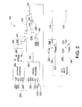
- FIG. 2 depicts a block diagram of an illustrative gas flow valve control algorithm 200 according to an exemplary embodiment of the invention.
- the algorithm 200 may be associated with the flow control module 116 of FIG. 1 .
- the algorithm 200 may produce a valve flow coefficient 258 for controlling one or more gas control valves in response to various parameters and measurements.
- the algorithm 200 may involve a series of calculations that can be used to actively control gas control valves (single, or multiples in parallel) to accurately meter fuel even when the gas control valves are operating unchoked.
- a desired gas turbine combustor energy flow rate 252 (e.g., BTU/sec) may be determined.
- the energy flow rate 252 may be based on a desired turbine load fuel command signal, also known as a fuel stroke reference (FSR) 250, which may be automatically determined by the controller 102 or selected by an operator. This value is generally represented as a percentage.
- the desired FSR 250 may be multiplied by a fuel energy per unit time of command 149 (e.g., BTU/sec/%), which may represent how much energy is required per unit of turbine load signal, or how much energy is present per unit of FSR. Multiplying the fuel energy per unit time of command 248 by the FSR 250 may provide an energy flow rate 252 (e.g., BTU/sec), which may represent the demand that is required for the turbine to reach the selected load.
- another calculation may be made to convert the previous energy flow rate 252 fuel command into a desired fuel flow rate 256 (e.g., LB/sec).
- the energy flow rate 252 may be divided by a gas energy per mass parameter 254 (e.g., BTU/LB), which may be a constant if the fuel source is very consistent, or may be provided from a sensor reading, for example, from a high-speed calorimeter or chromatograph to compensate for changes in the fuel energy content.
- the output of this calculation is a desired fuel flow rate 256 (e.g., LB /sec) to the combustor.
- the energy per mass parameter 254 e.g., BTU/LB
- the energy per mass parameter 254 may be manipulated intentionally and is intended to change.
- the universal valve flow equation can be represented as:
- the choked valve flow gain 238 can be used to determine how much the gas flow control valve 146 needs to be open to flow a certain amount of fuel by mass per unit time (e.g., CG/LB)/sec). Note that the output of this calculation will be the desired flow if the valves were choked.
- the unchoked flow parameter of the universal valve flow equation may be calculated in the unchoked parameter module 202.
- This version of the universal valve flow equation can be represented as: ⁇ 180 ⁇ A C 1 ⁇ C 2 ⁇ DP P 2 , where, according to an exemplary embodiment, the unchoked flow parameter A may be settable. In an exemplary embodiment, the unchoked flow parameter A may be set at approximately 3417.
- the output of the unchoked parameter module 202 is the unchoked valve factor 240.
- another calculation may be made by taking the sine value 208 of the median unchoked parameter 242, and multiplying the result 209 by the previously calculated choked valve flow gain 238.
- the median unchoked parameter 242 may be clamped between 1 and 0 via a constraining block 206.
- a value of 1 may represent a choked valve, whose flow would not vary with downstream pressure.
- the resulting median unchoked parameter 242 may then be multiplied by the choked valve gain 238 to produce an unchoked flow per control gas valve value. This value may then be inverted to produce gas flow gain 244 (e.g., CG/ LB /sec).
- the gas flow gain 24 4 may be multiplied by the desired fuel flow rate 256 (e.g., LB/sec) determined previously. Multiplying these two values together may yield the required total valve flow control 258 for controlling desired fuel flow. In certain embodiments, this total valve flow control 258 may also be known as the CG.
- the next portion of the gas flow valve control algorithm 200 may depend on how many gas control valves 142, 146, are present in the system. If only one valve 146 is present, then the total valve flow control 258 may be the desired gas control value of that valve. However, if two or more valves 142, 146, are present, the total valve flow control 258 may be split among these valves 142, 146 using a gas control valve split function 210. Exemplary embodiments of the gas control valve split function 210 may enable, for example, holding one valve at a constant low flow value while the other valve is opened all the way, at which point, the first valve may then be released to continue opening. Another exemplary embodiment may include opening all valves to an equal amount.
- Still other complicated systems may utilize the gas control valve split function 210 to split the total valve flow control 258 to each valve such that each valve may be dynamically altered to reflect changing turbine conditions depending on the needs of the specific turbine, for example, combustor stability or emissions control.
- this portion of the algorithm may assign a desired control value N 260, 266 to each gas control valve 142, 146.
- lookup tables 262, 264 may be used to compute the gas valve control position commands 216, 218 to each gas control valve 142, 146 in order to determine what stroke to open each gas control valve 142, 146. It is assumed that the gas control valves 142, 146 will have been flow tested (or that a representative table has been provided by the manufacturer), which may allow a simple 1-d interpolation 212, 214 to determine valve stroke based on the desired control value N 260, 266 for each valve.
- the gas flow control algorithm may be fully implemented many times per second in order to accurately and continuously deliver a desired amount of fuel to reach a desired load in a gas turbine where the gas control valves may be choked or unchoked.
- a desired fuel command 250 and an inlet pressure parameter 224 may be received.
- a choked valve flow factor 238 and an unchoked valve flow factor 240 of the gas flow control valve 145 may be determined based at least in part on the inlet pressure parameter 224.
- a gas flow gain 244 may be determined based at least in part on the inlet pressure parameter, or on the choked valve flow factor 238 and the unchoked valve flow factor 240, as determined in optional block 304.
- a valve flow coefficient 258 may be determined based at least in part on the desired fuel command 250 and the gas flow gain 244.
- the gas flow control valve 146 may be controlled based at least in part on the valve flow coefficient 258.
- exemplary embodiments of the invention can provide the technical effects of creating certain systems and methods that can provide for higher loading and operation of a gas turbine under low pressure fuel supply conditions.
- embodiments of the invention may allow a fuel supply system to be designed with a low fuel supply pressure in mind, or it could be used for a normal high pressure system which is experiencing a low pressure fuel supply due to some type of system failure.
- exemplary embodiments of the invention can provide the technical effects of creating certain systems and methods that can provide for reduction in size (or elimination of) a fuel gas compressor (FGC).
- FGC fuel gas compressor
- a fuel gas compressor to pressurize the fuel supply
- a site which would normally require a FGC to eliminate the FGC altogether from the design. This could significantly reduce the cost and design complexity of such a system.
- exemplary embodiments of the invention can also provide the technical effects of creating certain systems and methods that can improve efficiency.
- the smaller gas compressor has a further aspect in that the smaller compressor will be significantly more efficient. This is because the gas compressor consumes energy in order to pressurize the fuel. Since a fuel system which utilizes the invention can operate with a lower fuel supply pressure, the gas compressor will pressurize to a lower pressure and therefore consume less energy. This energy savings can be as high as several megawatts, and can be a continuous energy savings at all times during the operation of the unit.
- exemplary embodiments of the invention can also provide the technical effects of creating certain systems and methods that can lead to relatively cheaper gas control valve (GCV) design.
- GCV gas control valve
- the use of the invention's control system could allow the purchase of cheaper normal valves for such systems, which could then be operated unchoked.
- exemplary embodiments of the invention can also provide the technical effects of creating certain systems and methods that can tolerate a simpler gas control valve design. For example, unchoked valves generally have a much higher flow capacity than choked valves. For very high fuel flow systems, use of the invention's control system may enable a fuel system to be designed with fewer gas control valves in parallel, thus reducing the complexity and cost of the system.
- the gas flow control system 100 and the gas flow valve control algorithm 200 may include any number of software applications that are executed to facilitate any of the operations.
- one or more I/O interfaces may facilitate communication between the gas flow control system 100 and the gas flow valve control algorithm 200, and one or more input/output devices.
- a universal serial bus port, a serial port, a disk drive, a CD-ROM drive, and/or one or more user interface devices such as a display, keyboard, keypad, mouse, control panel, touch screen display, microphone, etc.
- the one or more I/O interfaces may be utilized to receive or collect data and/or user instructions from a wide variety of input devices. Received data may be processed by one or more computer processors as desired in various embodiments of the invention and/or stored in one or more memory devices.
- One or more network interfaces may facilitate connection of the gas flow control system 100 and the gas flow valve control algorithm 200 inputs and outputs to one or more suitable networks and/or connections; for example, the connections that facilitate communication with any number of sensors associated with the system.
- the one or more network interfaces may further facilitate connection to one or more suitable networks; for example, a local area network, a wide area network, the Internet, a cellular network, a radio frequency network, a BluetoothTM enabled network, a Wi-FiTMenabled network, a satellite-based network, any wired network, any wireless network, etc., for communication with external devices and/or systems.
- embodiments of the invention may include the gas flow control system 100 and the gas flow valve control algorithm 200 with more or less of the blocks or components illustrated in FIGs. 1 and 2 .
- These computer-executable program instructions may be loaded onto a general-purpose computer, a special-purpose computer, a processor, or other programmable data processing apparatus to produce a particular machine, such that the instructions that execute on the computer, processor, or other programmable data processing apparatus create means for implementing one or more functions specified in the flow diagram block or blocks.
- These computer program instructions may also be stored in a computer-readable memory that can direct a computer or other programmable data processing apparatus to function in a particular manner, such that the instructions stored in the computer-readable memory produce an article of manufacture including instruction means that implement one or more functions specified in the flow diagram block or blocks.
- embodiments of the invention may provide for a computer program product, comprising a computer-usable medium having a computer-readable program code or program instructions embodied therein, said computer-readable program code adapted to be executed to implement one or more functions specified in the flow diagram block or blocks.
- the computer program instructions may also be loaded onto a computer or other programmable data processing apparatus to cause a series of operational elements or steps to be performed on the computer or other programmable apparatus to produce a computer-implemented process such that the instructions that execute on the computer or other programmable apparatus provide elements or steps for implementing the functions specified in the flow diagram block or blocks.
- blocks of the block diagrams and flow diagrams support combinations of means for performing the specified functions, combinations of elements or steps for performing the specified functions and program instruction means for performing the specified functions. It will also be understood that each block of the block diagrams and flow diagrams, and combinations of blocks in the block diagrams and flow diagrams, can be implemented by special-purpose, hardware-based computer systems that perform the specified functions, elements or steps, or combinations of special-purpose hardware and computer instructions.
Landscapes
- Engineering & Computer Science (AREA)
- Chemical & Material Sciences (AREA)
- Combustion & Propulsion (AREA)
- Mechanical Engineering (AREA)
- General Engineering & Computer Science (AREA)
- Physics & Mathematics (AREA)
- Fluid Mechanics (AREA)
- Flow Control (AREA)
- Feedback Control In General (AREA)
Applications Claiming Priority (2)
| Application Number | Priority Date | Filing Date | Title |
|---|---|---|---|
| US26501609P | 2009-11-30 | 2009-11-30 | |
| US12/688,179 US8712665B2 (en) | 2009-11-30 | 2010-01-15 | Systems and methods for unchoked control of gas turbine fuel gas control valves |
Publications (3)
| Publication Number | Publication Date |
|---|---|
| EP2333281A2 true EP2333281A2 (de) | 2011-06-15 |
| EP2333281A3 EP2333281A3 (de) | 2014-06-18 |
| EP2333281B1 EP2333281B1 (de) | 2017-08-23 |
Family
ID=43597821
Family Applications (1)
| Application Number | Title | Priority Date | Filing Date |
|---|---|---|---|
| EP10191345.7A Active EP2333281B1 (de) | 2009-11-30 | 2010-11-16 | Systeme und Verfahren zur unverdrosselten Steuerung von Gasturbinen-Kraftstoff-Steuerventilen |
Country Status (2)
| Country | Link |
|---|---|
| US (1) | US8712665B2 (de) |
| EP (1) | EP2333281B1 (de) |
Families Citing this family (13)
| Publication number | Priority date | Publication date | Assignee | Title |
|---|---|---|---|---|
| US8127556B2 (en) * | 2008-10-08 | 2012-03-06 | General Electric Company | Method for operating a turbomachine having a syngas fuel supply system and a non-syngas fuel supply system |
| US8712665B2 (en) * | 2009-11-30 | 2014-04-29 | General Electric Company | Systems and methods for unchoked control of gas turbine fuel gas control valves |
| US20120180873A1 (en) * | 2011-01-14 | 2012-07-19 | General Electric Company | Method for replicating a pressure control valve with adjustable response characteristic |
| US9243804B2 (en) * | 2011-10-24 | 2016-01-26 | General Electric Company | System for turbine combustor fuel mixing |
| JP5743117B2 (ja) * | 2012-01-13 | 2015-07-01 | 三菱日立パワーシステムズ株式会社 | 燃料供給装置、燃料流量制御装置、およびガスタービン発電プラント |
| US20140137561A1 (en) * | 2012-11-19 | 2014-05-22 | General Electric Company | System and method for reducing modal coupling of combustion dynamics |
| US8919129B2 (en) * | 2013-03-28 | 2014-12-30 | Solar Turbines Inc. | Low flow correction for gas turbine engine fuel valve characteristics |
| US20140294559A1 (en) * | 2013-03-28 | 2014-10-02 | Solar Turbines Incorporated | Multiple mode gas turbine engine gas fuel system with integrated control |
| US9371917B2 (en) * | 2013-04-30 | 2016-06-21 | General Electric Company | Fuel conditioning system |
| US10830156B2 (en) * | 2014-02-19 | 2020-11-10 | Siemens Aktiengesellschaft | Fuel supply pipeline system for gas turbine |
| US10591161B2 (en) | 2018-06-09 | 2020-03-17 | Honeywell International Inc. | Systems and methods for valve and/or combustion applicance control |
| US20230036266A1 (en) * | 2021-07-27 | 2023-02-02 | Pratt & Whitney Canada Corp. | Controlling gaseous fuel flow |
| EP4417520A1 (de) * | 2023-02-15 | 2024-08-21 | Airbus Operations, S.L.U. | Kraftstoffkonditionierungssystem für ein flugzeug |
Family Cites Families (13)
| Publication number | Priority date | Publication date | Assignee | Title |
|---|---|---|---|---|
| US4146051A (en) * | 1976-01-10 | 1979-03-27 | Lucas Industries Limited | Fluid flow control system |
| JPH10159585A (ja) | 1996-11-27 | 1998-06-16 | Toshiba Corp | ガスタービン燃料供給方法およびその装置 |
| US6813875B2 (en) * | 2000-01-07 | 2004-11-09 | Honda Giken Kogyo Kabushiki Kaisha | Control system for gas-turbine engine |
| US6631334B2 (en) * | 2000-12-26 | 2003-10-07 | Mks Instruments, Inc. | Pressure-based mass flow controller system |
| US6795780B1 (en) * | 2001-09-27 | 2004-09-21 | Thomas Allen Hyde | Fluid energy pulse test system—transient, ramp, steady state tests |
| US7055395B2 (en) * | 2002-08-16 | 2006-06-06 | General Electric Company | Sulfur deposition control method and related control algorithm |
| US6980898B2 (en) * | 2003-12-19 | 2005-12-27 | Daimlerchrysler Corporation | Downshift acceleration control |
| JP4119908B2 (ja) * | 2005-09-14 | 2008-07-16 | 三菱重工業株式会社 | ガスタービンの燃焼制御装置 |
| US7481061B2 (en) * | 2005-11-10 | 2009-01-27 | Siemens Energy, Inc. | Fuel control for starting a gas turbine engine |
| US7549293B2 (en) * | 2006-02-15 | 2009-06-23 | General Electric Company | Pressure control method to reduce gas turbine fuel supply pressure requirements |
| US7607410B2 (en) * | 2006-06-12 | 2009-10-27 | Ford Global Technologies, Llc | System and method of controlling fuel delivery during positive valve overlap operation of an engine start |
| US8127556B2 (en) * | 2008-10-08 | 2012-03-06 | General Electric Company | Method for operating a turbomachine having a syngas fuel supply system and a non-syngas fuel supply system |
| US8712665B2 (en) * | 2009-11-30 | 2014-04-29 | General Electric Company | Systems and methods for unchoked control of gas turbine fuel gas control valves |
-
2010
- 2010-01-15 US US12/688,179 patent/US8712665B2/en active Active
- 2010-11-16 EP EP10191345.7A patent/EP2333281B1/de active Active
Non-Patent Citations (1)
| Title |
|---|
| None |
Also Published As
| Publication number | Publication date |
|---|---|
| EP2333281A3 (de) | 2014-06-18 |
| US8712665B2 (en) | 2014-04-29 |
| US20110130941A1 (en) | 2011-06-02 |
| EP2333281B1 (de) | 2017-08-23 |
Similar Documents
| Publication | Publication Date | Title |
|---|---|---|
| US8712665B2 (en) | Systems and methods for unchoked control of gas turbine fuel gas control valves | |
| EP2333280B1 (de) | Verfahren zur Steuerung der Kraftstoffmischung | |
| US12305853B2 (en) | Integrated flare combustion control | |
| EP2562612B1 (de) | Verfahren und Systeme zur Gasturbinenmodellierung mit adaptivem Kalmanfilter | |
| EP2570877A1 (de) | System und Verfahren zur Simulierung eines Gasturbinenbetriebs | |
| EP2423489A2 (de) | Verfahren zur Steuerung von Kraftstoffspaltung an eine Gasturbinenbrennkammer | |
| JP2011140947A (ja) | 機械内部の燃料流量を制御するシステムおよび方法 | |
| EP2599971B1 (de) | Dampferzeugungssysteme und Verfahren zur Betriebssteuerung dafür | |
| US9599028B2 (en) | Bulk flame temperature regulator for dry low emission engines | |
| CN104005854A (zh) | 用于调整燃气涡轮机的操作的系统和方法 | |
| US20150142188A1 (en) | Automated Commissioning of a Gas Turbine Combustion Control System | |
| EP3401600A1 (de) | System und Verfahren zur Erkennung van Ausblasen der Flamme in Gasturbinen | |
| US9639071B2 (en) | Method and system for combustion mode transfer for a gas turbine engine | |
| JP2017115871A (ja) | スケーリングファクタを用いてパワー出力/放出パラメータを調節するガスタービンにおける複合確率的制御の応用、関連した制御システム、コンピュータプログラム製品、および方法 | |
| JP2017115867A (ja) | スケーリングファクタを用いてパワー出力/放出パラメータを調節するガスタービンにおける複合確率的制御、関連した制御システム、コンピュータプログラム製品、および方法 | |
| CN100383505C (zh) | 燃烧温度高速检测设备 | |
| JP2017110644A (ja) | スケーリング係数を用いたパワー出力−排出量パラメータのためのガスタービンのチューニングにおける複合確率的制御の適用、関連する制御システム、コンピュータプログラム製品および方法 | |
| US9632011B2 (en) | System and method for testing a gas turbine | |
| US9500136B2 (en) | Systems and methods for generating variable ramp rates for turbomachinery | |
| RU2181854C1 (ru) | Способ управления работой комплекса агрегатов компрессорного цеха | |
| CN108119237B (zh) | 无模型燃烧动力自动调谐 | |
| EP2901020B1 (de) | Verdichterprüfstand mit erzielung des druckverhältnisses durch drosselung | |
| Skakovsky et al. | Increasing of precise estimation of optimal criteria boiler functioning | |
| WO2025109967A1 (ja) | ガスタービンシステムおよびガスタービンシステムを改造するための方法 |
Legal Events
| Date | Code | Title | Description |
|---|---|---|---|
| PUAI | Public reference made under article 153(3) epc to a published international application that has entered the european phase |
Free format text: ORIGINAL CODE: 0009012 |
|
| AK | Designated contracting states |
Kind code of ref document: A2 Designated state(s): AL AT BE BG CH CY CZ DE DK EE ES FI FR GB GR HR HU IE IS IT LI LT LU LV MC MK MT NL NO PL PT RO RS SE SI SK SM TR |
|
| AX | Request for extension of the european patent |
Extension state: BA ME |
|
| PUAL | Search report despatched |
Free format text: ORIGINAL CODE: 0009013 |
|
| AK | Designated contracting states |
Kind code of ref document: A3 Designated state(s): AL AT BE BG CH CY CZ DE DK EE ES FI FR GB GR HR HU IE IS IT LI LT LU LV MC MK MT NL NO PL PT RO RS SE SI SK SM TR |
|
| AX | Request for extension of the european patent |
Extension state: BA ME |
|
| RIC1 | Information provided on ipc code assigned before grant |
Ipc: F02C 7/232 20060101ALI20140513BHEP Ipc: F02C 9/32 20060101ALI20140513BHEP Ipc: F02C 7/22 20060101AFI20140513BHEP Ipc: F02C 9/24 20060101ALI20140513BHEP Ipc: F02C 9/26 20060101ALI20140513BHEP |
|
| 17P | Request for examination filed |
Effective date: 20141218 |
|
| RBV | Designated contracting states (corrected) |
Designated state(s): AL AT BE BG CH CY CZ DE DK EE ES FI FR GB GR HR HU IE IS IT LI LT LU LV MC MK MT NL NO PL PT RO RS SE SI SK SM TR |
|
| GRAP | Despatch of communication of intention to grant a patent |
Free format text: ORIGINAL CODE: EPIDOSNIGR1 |
|
| RIC1 | Information provided on ipc code assigned before grant |
Ipc: F02C 9/32 20060101ALI20170301BHEP Ipc: F02C 7/232 20060101ALI20170301BHEP Ipc: F02C 7/22 20060101AFI20170301BHEP Ipc: F02C 9/26 20060101ALI20170301BHEP Ipc: F02C 9/24 20060101ALI20170301BHEP |
|
| INTG | Intention to grant announced |
Effective date: 20170329 |
|
| GRAS | Grant fee paid |
Free format text: ORIGINAL CODE: EPIDOSNIGR3 |
|
| GRAA | (expected) grant |
Free format text: ORIGINAL CODE: 0009210 |
|
| AK | Designated contracting states |
Kind code of ref document: B1 Designated state(s): AL AT BE BG CH CY CZ DE DK EE ES FI FR GB GR HR HU IE IS IT LI LT LU LV MC MK MT NL NO PL PT RO RS SE SI SK SM TR |
|
| REG | Reference to a national code |
Ref country code: GB Ref legal event code: FG4D |
|
| REG | Reference to a national code |
Ref country code: CH Ref legal event code: EP |
|
| REG | Reference to a national code |
Ref country code: AT Ref legal event code: REF Ref document number: 921607 Country of ref document: AT Kind code of ref document: T Effective date: 20170915 |
|
| REG | Reference to a national code |
Ref country code: IE Ref legal event code: FG4D |
|
| REG | Reference to a national code |
Ref country code: DE Ref legal event code: R096 Ref document number: 602010044570 Country of ref document: DE |
|
| REG | Reference to a national code |
Ref country code: FR Ref legal event code: PLFP Year of fee payment: 8 |
|
| REG | Reference to a national code |
Ref country code: NL Ref legal event code: MP Effective date: 20170823 |
|
| REG | Reference to a national code |
Ref country code: LT Ref legal event code: MG4D |
|
| REG | Reference to a national code |
Ref country code: AT Ref legal event code: MK05 Ref document number: 921607 Country of ref document: AT Kind code of ref document: T Effective date: 20170823 |
|
| PG25 | Lapsed in a contracting state [announced via postgrant information from national office to epo] |
Ref country code: NO Free format text: LAPSE BECAUSE OF FAILURE TO SUBMIT A TRANSLATION OF THE DESCRIPTION OR TO PAY THE FEE WITHIN THE PRESCRIBED TIME-LIMIT Effective date: 20171123 Ref country code: AT Free format text: LAPSE BECAUSE OF FAILURE TO SUBMIT A TRANSLATION OF THE DESCRIPTION OR TO PAY THE FEE WITHIN THE PRESCRIBED TIME-LIMIT Effective date: 20170823 Ref country code: SE Free format text: LAPSE BECAUSE OF FAILURE TO SUBMIT A TRANSLATION OF THE DESCRIPTION OR TO PAY THE FEE WITHIN THE PRESCRIBED TIME-LIMIT Effective date: 20170823 Ref country code: LT Free format text: LAPSE BECAUSE OF FAILURE TO SUBMIT A TRANSLATION OF THE DESCRIPTION OR TO PAY THE FEE WITHIN THE PRESCRIBED TIME-LIMIT Effective date: 20170823 Ref country code: HR Free format text: LAPSE BECAUSE OF FAILURE TO SUBMIT A TRANSLATION OF THE DESCRIPTION OR TO PAY THE FEE WITHIN THE PRESCRIBED TIME-LIMIT Effective date: 20170823 Ref country code: NL Free format text: LAPSE BECAUSE OF FAILURE TO SUBMIT A TRANSLATION OF THE DESCRIPTION OR TO PAY THE FEE WITHIN THE PRESCRIBED TIME-LIMIT Effective date: 20170823 Ref country code: FI Free format text: LAPSE BECAUSE OF FAILURE TO SUBMIT A TRANSLATION OF THE DESCRIPTION OR TO PAY THE FEE WITHIN THE PRESCRIBED TIME-LIMIT Effective date: 20170823 |
|
| PG25 | Lapsed in a contracting state [announced via postgrant information from national office to epo] |
Ref country code: RS Free format text: LAPSE BECAUSE OF FAILURE TO SUBMIT A TRANSLATION OF THE DESCRIPTION OR TO PAY THE FEE WITHIN THE PRESCRIBED TIME-LIMIT Effective date: 20170823 Ref country code: LV Free format text: LAPSE BECAUSE OF FAILURE TO SUBMIT A TRANSLATION OF THE DESCRIPTION OR TO PAY THE FEE WITHIN THE PRESCRIBED TIME-LIMIT Effective date: 20170823 Ref country code: IS Free format text: LAPSE BECAUSE OF FAILURE TO SUBMIT A TRANSLATION OF THE DESCRIPTION OR TO PAY THE FEE WITHIN THE PRESCRIBED TIME-LIMIT Effective date: 20171223 Ref country code: BG Free format text: LAPSE BECAUSE OF FAILURE TO SUBMIT A TRANSLATION OF THE DESCRIPTION OR TO PAY THE FEE WITHIN THE PRESCRIBED TIME-LIMIT Effective date: 20171123 Ref country code: GR Free format text: LAPSE BECAUSE OF FAILURE TO SUBMIT A TRANSLATION OF THE DESCRIPTION OR TO PAY THE FEE WITHIN THE PRESCRIBED TIME-LIMIT Effective date: 20171124 Ref country code: ES Free format text: LAPSE BECAUSE OF FAILURE TO SUBMIT A TRANSLATION OF THE DESCRIPTION OR TO PAY THE FEE WITHIN THE PRESCRIBED TIME-LIMIT Effective date: 20170823 Ref country code: PL Free format text: LAPSE BECAUSE OF FAILURE TO SUBMIT A TRANSLATION OF THE DESCRIPTION OR TO PAY THE FEE WITHIN THE PRESCRIBED TIME-LIMIT Effective date: 20170823 |
|
| PG25 | Lapsed in a contracting state [announced via postgrant information from national office to epo] |
Ref country code: RO Free format text: LAPSE BECAUSE OF FAILURE TO SUBMIT A TRANSLATION OF THE DESCRIPTION OR TO PAY THE FEE WITHIN THE PRESCRIBED TIME-LIMIT Effective date: 20170823 Ref country code: DK Free format text: LAPSE BECAUSE OF FAILURE TO SUBMIT A TRANSLATION OF THE DESCRIPTION OR TO PAY THE FEE WITHIN THE PRESCRIBED TIME-LIMIT Effective date: 20170823 |
|
| REG | Reference to a national code |
Ref country code: DE Ref legal event code: R097 Ref document number: 602010044570 Country of ref document: DE |
|
| PG25 | Lapsed in a contracting state [announced via postgrant information from national office to epo] |
Ref country code: SM Free format text: LAPSE BECAUSE OF FAILURE TO SUBMIT A TRANSLATION OF THE DESCRIPTION OR TO PAY THE FEE WITHIN THE PRESCRIBED TIME-LIMIT Effective date: 20170823 Ref country code: IT Free format text: LAPSE BECAUSE OF FAILURE TO SUBMIT A TRANSLATION OF THE DESCRIPTION OR TO PAY THE FEE WITHIN THE PRESCRIBED TIME-LIMIT Effective date: 20170823 Ref country code: SK Free format text: LAPSE BECAUSE OF FAILURE TO SUBMIT A TRANSLATION OF THE DESCRIPTION OR TO PAY THE FEE WITHIN THE PRESCRIBED TIME-LIMIT Effective date: 20170823 Ref country code: EE Free format text: LAPSE BECAUSE OF FAILURE TO SUBMIT A TRANSLATION OF THE DESCRIPTION OR TO PAY THE FEE WITHIN THE PRESCRIBED TIME-LIMIT Effective date: 20170823 |
|
| PG25 | Lapsed in a contracting state [announced via postgrant information from national office to epo] |
Ref country code: MC Free format text: LAPSE BECAUSE OF FAILURE TO SUBMIT A TRANSLATION OF THE DESCRIPTION OR TO PAY THE FEE WITHIN THE PRESCRIBED TIME-LIMIT Effective date: 20170823 |
|
| PLBE | No opposition filed within time limit |
Free format text: ORIGINAL CODE: 0009261 |
|
| STAA | Information on the status of an ep patent application or granted ep patent |
Free format text: STATUS: NO OPPOSITION FILED WITHIN TIME LIMIT |
|
| GBPC | Gb: european patent ceased through non-payment of renewal fee |
Effective date: 20171123 |
|
| 26N | No opposition filed |
Effective date: 20180524 |
|
| PG25 | Lapsed in a contracting state [announced via postgrant information from national office to epo] |
Ref country code: SI Free format text: LAPSE BECAUSE OF FAILURE TO SUBMIT A TRANSLATION OF THE DESCRIPTION OR TO PAY THE FEE WITHIN THE PRESCRIBED TIME-LIMIT Effective date: 20170823 Ref country code: LU Free format text: LAPSE BECAUSE OF NON-PAYMENT OF DUE FEES Effective date: 20171116 |
|
| REG | Reference to a national code |
Ref country code: BE Ref legal event code: MM Effective date: 20171130 |
|
| REG | Reference to a national code |
Ref country code: IE Ref legal event code: MM4A |
|
| PG25 | Lapsed in a contracting state [announced via postgrant information from national office to epo] |
Ref country code: MT Free format text: LAPSE BECAUSE OF NON-PAYMENT OF DUE FEES Effective date: 20171116 |
|
| REG | Reference to a national code |
Ref country code: FR Ref legal event code: PLFP Year of fee payment: 9 |
|
| PG25 | Lapsed in a contracting state [announced via postgrant information from national office to epo] |
Ref country code: IE Free format text: LAPSE BECAUSE OF NON-PAYMENT OF DUE FEES Effective date: 20171116 |
|
| PG25 | Lapsed in a contracting state [announced via postgrant information from national office to epo] |
Ref country code: BE Free format text: LAPSE BECAUSE OF NON-PAYMENT OF DUE FEES Effective date: 20171130 Ref country code: GB Free format text: LAPSE BECAUSE OF NON-PAYMENT OF DUE FEES Effective date: 20171123 |
|
| PG25 | Lapsed in a contracting state [announced via postgrant information from national office to epo] |
Ref country code: HU Free format text: LAPSE BECAUSE OF FAILURE TO SUBMIT A TRANSLATION OF THE DESCRIPTION OR TO PAY THE FEE WITHIN THE PRESCRIBED TIME-LIMIT; INVALID AB INITIO Effective date: 20101116 |
|
| PG25 | Lapsed in a contracting state [announced via postgrant information from national office to epo] |
Ref country code: CY Free format text: LAPSE BECAUSE OF NON-PAYMENT OF DUE FEES Effective date: 20170823 |
|
| PG25 | Lapsed in a contracting state [announced via postgrant information from national office to epo] |
Ref country code: MK Free format text: LAPSE BECAUSE OF FAILURE TO SUBMIT A TRANSLATION OF THE DESCRIPTION OR TO PAY THE FEE WITHIN THE PRESCRIBED TIME-LIMIT Effective date: 20170823 |
|
| PGFP | Annual fee paid to national office [announced via postgrant information from national office to epo] |
Ref country code: CZ Payment date: 20191025 Year of fee payment: 10 |
|
| PG25 | Lapsed in a contracting state [announced via postgrant information from national office to epo] |
Ref country code: TR Free format text: LAPSE BECAUSE OF FAILURE TO SUBMIT A TRANSLATION OF THE DESCRIPTION OR TO PAY THE FEE WITHIN THE PRESCRIBED TIME-LIMIT Effective date: 20170823 |
|
| PGFP | Annual fee paid to national office [announced via postgrant information from national office to epo] |
Ref country code: CH Payment date: 20191022 Year of fee payment: 10 |
|
| PG25 | Lapsed in a contracting state [announced via postgrant information from national office to epo] |
Ref country code: PT Free format text: LAPSE BECAUSE OF FAILURE TO SUBMIT A TRANSLATION OF THE DESCRIPTION OR TO PAY THE FEE WITHIN THE PRESCRIBED TIME-LIMIT Effective date: 20170823 |
|
| PG25 | Lapsed in a contracting state [announced via postgrant information from national office to epo] |
Ref country code: AL Free format text: LAPSE BECAUSE OF FAILURE TO SUBMIT A TRANSLATION OF THE DESCRIPTION OR TO PAY THE FEE WITHIN THE PRESCRIBED TIME-LIMIT Effective date: 20170823 |
|
| REG | Reference to a national code |
Ref country code: CH Ref legal event code: PL |
|
| PG25 | Lapsed in a contracting state [announced via postgrant information from national office to epo] |
Ref country code: CZ Free format text: LAPSE BECAUSE OF NON-PAYMENT OF DUE FEES Effective date: 20201116 |
|
| PG25 | Lapsed in a contracting state [announced via postgrant information from national office to epo] |
Ref country code: CH Free format text: LAPSE BECAUSE OF NON-PAYMENT OF DUE FEES Effective date: 20201130 Ref country code: LI Free format text: LAPSE BECAUSE OF NON-PAYMENT OF DUE FEES Effective date: 20201130 |
|
| P01 | Opt-out of the competence of the unified patent court (upc) registered |
Effective date: 20230522 |
|
| REG | Reference to a national code |
Ref country code: DE Ref legal event code: R081 Ref document number: 602010044570 Country of ref document: DE Owner name: GENERAL ELECTRIC TECHNOLOGY GMBH, CH Free format text: FORMER OWNER: GENERAL ELECTRIC COMPANY, SCHENECTADY, NY, US |
|
| PGFP | Annual fee paid to national office [announced via postgrant information from national office to epo] |
Ref country code: DE Payment date: 20251022 Year of fee payment: 16 |
|
| PGFP | Annual fee paid to national office [announced via postgrant information from national office to epo] |
Ref country code: FR Payment date: 20251023 Year of fee payment: 16 |