EP2901020B1 - Verdichterprüfstand mit erzielung des druckverhältnisses durch drosselung - Google Patents
Verdichterprüfstand mit erzielung des druckverhältnisses durch drosselung Download PDFInfo
- Publication number
- EP2901020B1 EP2901020B1 EP13756951.3A EP13756951A EP2901020B1 EP 2901020 B1 EP2901020 B1 EP 2901020B1 EP 13756951 A EP13756951 A EP 13756951A EP 2901020 B1 EP2901020 B1 EP 2901020B1
- Authority
- EP
- European Patent Office
- Prior art keywords
- compressor
- control
- pressure ratio
- processor
- operable
- Prior art date
- Legal status (The legal status is an assumption and is not a legal conclusion. Google has not performed a legal analysis and makes no representation as to the accuracy of the status listed.)
- Active
Links
Images


Classifications
-
- F—MECHANICAL ENGINEERING; LIGHTING; HEATING; WEAPONS; BLASTING
- F04—POSITIVE - DISPLACEMENT MACHINES FOR LIQUIDS; PUMPS FOR LIQUIDS OR ELASTIC FLUIDS
- F04D—NON-POSITIVE-DISPLACEMENT PUMPS
- F04D27/00—Control, e.g. regulation, of pumps, pumping installations or pumping systems specially adapted for elastic fluids
- F04D27/001—Testing thereof; Determination or simulation of flow characteristics; Stall or surge detection, e.g. condition monitoring
-
- F—MECHANICAL ENGINEERING; LIGHTING; HEATING; WEAPONS; BLASTING
- F04—POSITIVE - DISPLACEMENT MACHINES FOR LIQUIDS; PUMPS FOR LIQUIDS OR ELASTIC FLUIDS
- F04D—NON-POSITIVE-DISPLACEMENT PUMPS
- F04D27/00—Control, e.g. regulation, of pumps, pumping installations or pumping systems specially adapted for elastic fluids
- F04D27/02—Surge control
- F04D27/0253—Surge control by throttling
-
- G—PHYSICS
- G01—MEASURING; TESTING
- G01M—TESTING STATIC OR DYNAMIC BALANCE OF MACHINES OR STRUCTURES; TESTING OF STRUCTURES OR APPARATUS, NOT OTHERWISE PROVIDED FOR
- G01M15/00—Testing of engines
- G01M15/14—Testing gas-turbine engines or jet-propulsion engines
Definitions
- This disclosure generally relates to power generation systems and in particular to systems and methods for validating the operation of a compressor.
- Compressors are typical power generation components for conventional power generating stations. Effective testing and validation of a compressor can increase the efficiency and productivity of the overall power generating station. In conventional power generating stations, validating a compressor can be an expensive and time consuming process wherein the compressor's operation must be evaluated over a wide range of operational test points.
- the document WO 2011/119339 A1 discloses a method of validating the operation of a compressor wherein the compressor pressure ratio is controlled in a closed loop involving pressure measurements and the control of an adjustable throttle valve placed downstream of the compressor.
- Certain embodiments of the disclosure may include systems and methods for operating and validating a compressor.
- Claim 1 defines a method for validating the operation of a compressor.
- Claim 7 defines a system for validating the operation of a compressor.
- Claim 15 defines a computer-readable medium storing a program that allows to perform the method of claim 1.
- validating a compressor can be achieved by modulating a discharge area of the compressor.
- modulating, varying, or otherwise controlling the discharge area of the compressor one can simulate compressor operation when the compressor operates in conjunction with a turbine in a power generating station.
- Controlling the discharge area can be accomplished by using a computer processor with one or more computer-executable instructions.
- the instructions can include any number of control modes.
- a control mode can be governed by an algorithm operable to calculate a compressor pressure ratio (CPR).
- the computer processor may use any number of control modes to adjust the variable flow area downstream of the compressor discharge to achieve a desired CPR.
- the control modes can include, but are not limited to, closed loop pressure ratio control; manual control of the portion of the variable flow area; and dynamic control of the portion of the variable flow area.
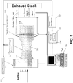
- FIG. 1 is a schematic view of an example system 100 that can include a compressor 102 with an inlet 104 and a discharge 106.
- the system 100 can utilize various types of compressors, such as, but not limited to, axial-type, centrifugal-type, or screw-type configurations.
- the compressor 102 can receive gas or fluid flow through the inlet 104, and can deliver a compressed gas or fluid flow to the discharge 106.
- the gas or fluid flow rate exiting the discharge 106 can be controlled by one or more modulating devices, such as valves 108.
- valves 108 shown in this embodiment can modulate the gas or fluid flow rate by increasing or decreasing a respective aperture size associated with each valve.
- the change in valve aperture size is inversely proportional to the pressure of the gas or fluid exiting the discharge.
- increasing the valve aperture size lowers the pressure of the gas or fluid at the discharge 106.
- the configuration of valves 108 in FIG. 1 is shown as a series of 3 valves in a parallel orientation with each other from a common header connected to an annular ring around the compressor discharge 106.
- Other types and/or configurations of modulation devices and/or valves can exist in other embodiments of the disclosure.
- the system 100 can also include any number of sensors, such as 110, 112, 114, operable to obtain or otherwise receive compressor operating parameter data.
- the sensors 110, 112, 114 can capture compressor operating parameters, including, but not limited to, dynamic fluid pressure, fluid flow rate, and compressor speed.
- the sensors 110, 112, 114 can be respectively located or otherwise positioned at the inlet 104 and discharge 106 of the compressor 102.
- any number of intermediate sensors 114 can be located or otherwise positioned between the inlet 104 and discharge 106.
- compressor operating parameter data obtained or otherwise received by the sensors 110, 112, 114 can be transmitted to a computer processor 116.
- compressor operating parameter data can be transmitted to a remote storage device 118 for storage, wherein the remote storage device 118 can be externally coupled to the computer processor 116.
- a storage device such as memory 120, may exist physically inside the processor 116.
- the storage device 118 may include, but not be limited to, random access memory (RAM), a hard drive, optical disk, magnetic tape, or other similar types of data storage.
- the computer processor 116 shown in FIG. 1 can be operable to communicate with the remote storage device 118 and/or memory 120 to execute one or more computer-executable instructions operable to calculate a compressor pressure ratio (CPR) associated with the compressor 102.
- CPR compressor pressure ratio
- the CPR can be calculated using a formula, such as: (Pressure (2) - Pressure (1))/Pressure (2), wherein Pressure (1) can be measured at the inlet 104, and Pressure (2) can be measured at the discharge 106.
- the computer processor 116 can control the pressure of the gas or fluid exiting the discharge 106 by sending a signal to adjust one or more of the valves 108.
- an external user interface such as 122 can generate and transmit a signal to the computer processor 116 to adjust one or more of the valves 108.
- the external user interface 122 can be operable to implement a direct adjustment to one or more of the valves 108 without a signal input from the computer processor 116.
- the external user interface 122 shown in FIG. 1 can include, but is not limited to, a processor-based device, a computer, a tablet, a laptop computer, a server, a mainframe computer, or any other similar type device for receiving a user input.
- FIG. 2 illustrates an example processor/controller and associated system components 200, this system being suitable to perform the method of the invention, which is explained in detail in fig. 3 and the corresponding passages here below.
- data acquisition and processing of a compressor operating system can include a compressor 202, sensors 204, 206, 208, valves 210, a processor 212, and an external manual control input device 228.
- the sensors 204, 206, 208 receive compressor operating data.
- the sensor data can be received by the processor 212.
- the processor 212 can be operable to control subsequent operation of the compressor 202 using at least one control mode. For example, the processor 212 can initiate an algorithm which receives the data from the sensors 204, 206, 208 and sends a modulating signal to the valves 210.
- the compressor 202 can be operable to compress a fluid or gas as the fluid or gas enters and exits the compressor 202.
- the compressor 202 can function in a transient state or steady state.
- transient state operation can occur when the compressor speed is variable, wherein the compressor is accelerating to full operational speed or decelerating from full operational speed.
- Steady state operation can occur when the compressor speed is at full constant speed.
- sensors 204, 206, 208 can be placed at multiple locations on the compressor 202.
- sensors can be placed at the inlet 204 and discharge 206.
- sensors can be placed on the compressor in an intermediate position 208 at locations between the inlet 204 and discharge 206.
- the sensors 204, 206, 208 can be operable to receive any type of compressor operating data, including but not limited to fluid pressure, fluid flow rate and compressor speed.
- the sensors 204, 206, 208 can be dynamic pressure sensors.
- the valves 210 shown in this embodiment can modulate gas or fluid flow rate by increasing or decreasing an aperture size.
- the operation of valves 210 can be controlled by the inputs received by the processor 212.
- the processor 212 can both receive inputs from the compressor sensors 204, 206, 208 and send output to the sensors 204, 206, 208 and valves 210.
- the output provided by the processor 212 can control the compressor operation. Further, the output generated by the processor 212 can be determined from a control mode.
- the processor 212 can control the compressor 202 using dynamic control modes 214.
- the dynamic control modes 214 can include but are not limited to closed loop CPR control 216 and open loop startup/shutdown control 218.
- processor 212 can control the compressor 202 using steady state control modes 220.
- the steady state control modes 220 can include, but are not limited to, closed loop CPR 216 and open loop manual control 222.
- the compressor 202 can operate in steady state, and the processor 212 can initiate a steady state control mode 220.
- the processor 212 can receive inputs from the sensors 204, 206, 208 to calculate the CPR process variable 224.
- the CPR calculation 224 can be made by evaluating the pressure ratio of two points located in the compressor 202.
- the processor 212 can calculate the pressure ratio using the pressure measurements at the inlet 204 and discharge 206 of the compressor 202.
- the CPR 224 can be stored and compared to preset values, or set points. Further, divergence from the preset value can initiate an automatic adjustment to vary fluid flow downstream from the compressor discharge.
- the compressor 202 can be operated at steady state speed, and the processor can be governed by open loop manual control 222.
- the manual control 222 can supersede a prompt to adjust the valves based on the CPR process variable 224 used to control other modes.
- the manual input to the valves 210 can be provided by an external manual input device 228 either via the manual control 222 or directly by the external manual input device 228.
- the external manual input device 228 may include, but is not limited to, a keyboard, touch screen, mouse, push button, knob, dial, or similar type of input device.
- the processor 212 can control the compressor using dynamic control 214, wherein dynamic control 214 can operate using an open loop or closed loop control algorithm. Dynamic control 214 can be applied when the compressor 202 is operating in the transient state. Further, closed loop operation under dynamic control 214 can also use a process variable, such as the CPR process variable 216, to modulate the aperture of the discharge valves 210.
- the open loop dynamic control can be controlled in an open loop startup/shutdown control 218 wherein the compressor shaft speed 226 can be directly correlated to pre-set valve apertures.
- the compressor shaft speed 226 can serve as a process variable for an open control loop.
- startup/shutdown control 218 can be modulated by other compressor operating parameters.
- the processor 212 can be further operable to implement a surge protection algorithm operable to supersede closed loop pressure ratio control, manual valve position control of the portion of the variable flow area, or dynamic control of the portion of the variable flow area.
- the surge protection algorithm can be implemented to prevent the compressor from operating under surge conditions.
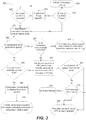
- FIG. 3 is a flowchart representing an example method for validating a compressor.
- the example method 300 can be implemented by either or both systems 100, 200, and some or all of the system components shown in FIGs. 1 and 2 .
- the method 300 begins at block 305, in which compressor control is initiated. Block 305 is followed by decision block 310, in which a determination is made whether surge conditions are present. If determined that the compressor is operating under surge conditions, then YES branch is followed and the method 300 continues at block 315. At block 315, the surge protection algorithm is initiated. At the conclusion of the surge protection algorithm, the method 300 continues to decision block 320. At block 320, a determination is made if surge conditions have been removed. If the surge conditions have not been removed the operation reverts back to initiating the surge protection algorithm at block 315.
- the NO branch is followed to block 325 and the compressor operates in the transient state or steady state.
- the transient state characterizes operation when the compressor is operating less than full operation speed and; steady state operation occurs when the compressor is operating at full constant speed.
- Block 325 is followed by decision block 330, in which a determination is made whether the compressor is operating at steady state speed. If the compressor is operating a steady speed, the YES branch is followed decision block 335, in which a determination is made whether the compressor is being manually controlled. If the compressor is being manually controlled, the YES branch is followed to block 340, in which the compressor is operating in manual control mode, wherein the flow modulating devices are opened and closed using a manual input.
- decision block 345 a determination is made whether the transient state is controlled by an open loop. If the compressor is operating in the transient state under open loop control, the YES branch is followed to block 350, wherein the open loop is regulated by a startup/shut down algorithm. Block 350 is followed by block 355, in which during the startup/shutdown algorithm, throttle valves open based on a compressor schedule directly correlated to the compressor shaft speed.
- Block 360 in which the compressor operates in a closed loop CPR Control Mode wherein the throttle valves adjust based on the feedback of the calculated CPR process variable.
- Block 360 is followed by decision block 365, in which a determination is made whether the calculated CPR is greater than the CPR preset value, wherein the calculated CPR is compared to a stored value of CPR. If the CPR is greater than the CPR preset value, the method 300 moves to block 380, wherein the compressor valves modulate to reach the CPR preset value.
- decision block 370 a determination is made whether the CPR is less than the CPR preset value. If the CPR is not less than the preset value, the NO branch is followed to block 375, in which the closed control algorithm does not perform an action on the modulating valves. If the CPR is less than the preset value, the YES branch is followed to block 380, in which the compressor valves modulate to reach the CPR preset value.
- the method 400 can include fewer or greater numbers of operations than those described above, and may be performed in a different sequential order than described above.
- the example method 400 is not part of the invention. However, it can be implemented by either or both the systems 100, 200, and some or all of the system components shown in FIGs. 1 and 2 .
- the method 400 starts in block 402, and according to an example embodiment of the disclosure, includes receiving compressor operating parameter data from a plurality of sensors.
- the method 400 includes providing adjusting a portion of a variable flow area downstream of a compressor discharge to achieve a desired compressor pressure ratio or compressor speed.
- adjusting the portion of the variable flow area downstream of the compressor discharge to achieve the desired compressor pressure ratio can include adjusting a throttle device operable to modulate the variable flow area.
- adjusting the portion of the variable flow area downstream of the compressor discharge to achieve the desired compressor pressure ratio can include closed loop pressure ratio control, manual control of the portion of the variable flow area, or dynamic control of the portion of the variable flow area.
- the method 400 can further include, based at least in part on detection of a surge event, overriding the closed loop pressure ratio control, manual valve position control of the portion of the variable flow area, or dynamic control of the portion of the variable flow area.
- dynamic control can include modulating the compressor shaft speed while performing closed loop control of compressor pressure ratio.
- the method 400 can further include calculating the desired compressor pressure ratio using at least two sensors; and storing the desired compressor pressure ratio.
- calculating the desired compressor pressure ratio using at least two sensors can further include calculating an inlet sensor pressure divided by a discharge sensor pressure; or calculating differential pressure between a compressor inlet and a compressor discharge.
- the method 400 can include fewer or greater numbers of operations than those described above, and may be performed in a different sequential order than described above.
- references are made to block diagrams of systems, and methods and computer program products according to example embodiments of the disclosure. It will be understood that at least some of the blocks of the block diagrams, and combinations of blocks in the block diagrams, respectively, may be implemented at least partially by computer program instructions. These computer program instructions may be loaded onto a general purpose computer, special purpose computer, special purpose hardware-based computer, or other programmable data processing apparatus to produce a machine, such that the instructions which execute on the computer or other programmable data processing apparatus and create means for implementing the functionality of at least some of the blocks of the block diagrams, or combinations of the blocks in the block diagrams discussed.
- These computer program instructions may also be stored in a computer readable memory that can direct a computer or other programmable data processing apparatus to function in a particular manner, such that the instructions stored in the computer-readable memory produce instruction means that implement the function specified in the block or blocks.
- the computer program instructions may also be loaded onto a computer or other programmable data processing apparatus to cause a series of operational steps to be performed on the computer or other programmable apparatus to produce a computer implemented process such that the instructions that execute on the computer or other programmable apparatus provide steps for implementing the functions specified in the block or blocks.
- One or more components of the systems and one or more elements of the methods described herein may be implemented through an application program running on an operating system of a computer. They also may be practiced with other computer system configurations, including hand-held devices, multiprocessor systems, microprocessor based, or programmable consumer electronics, mini-computers, main computers, etc.
- Application programs that are components of the systems and methods described herein may include routines, programs, components, data structures, etc. that implement certain abstract data types and perform certain tasks or actions.
- the application program in whole or in part
- the application program may be located in local memory, or in other storage.
- the application program in whole or in part
Landscapes
- Engineering & Computer Science (AREA)
- Mechanical Engineering (AREA)
- General Engineering & Computer Science (AREA)
- Chemical & Material Sciences (AREA)
- Combustion & Propulsion (AREA)
- Physics & Mathematics (AREA)
- General Physics & Mathematics (AREA)
- Control Of Positive-Displacement Pumps (AREA)
- Control Of Positive-Displacement Air Blowers (AREA)
Claims (15)
- Verfahren zum Validieren des Betriebs eines Verdichters, wobei das Verfahren umfasst:Empfangen von Betriebsparameterdaten des Verdichters von einer Vielzahl von Sensoren durch einen Prozessor;Durchführen einer Bestimmung, ob der Verdichter in (i) einem nicht stationären Drehzahlzustand oder (ii) einem stationären Drehzahlzustand arbeitet; undAnpassen, auf der Grundlage der Bestimmung, eines Abschnitts eines variablen Strömungsquerschnitts in Strömungsrichtung nach dem Auslass des Verdichters durch Anpassen eines oder mehrerer Ventile, um ein gewünschtes Verdichterdruckverhältnis zu erreichen, umfassend: (i) dynamische Steuerung, wenn der Verdichter im nicht stationären Drehzahlzustand arbeitet, oder (ii) stationäre Steuerung, wenn der Verdichter im stationären Drehzahlzustand arbeitet, wobei die dynamische Steuerung umfasst:Bestimmen, ob der Verdichter im nicht stationären Drehzahlzustand unter (i) Steuerung oder (ii) Regelung arbeitet; undAnpassen des einen oder der mehreren Ventile mindestens teilweise auf der Grundlage: (i) eines Verdichterzeitplans, der mit der Verdichterwellendrehzahl korreliert ist, wenn der Verdichter im nicht stationären Drehzahlzustand unter Steuerung betrieben wird, wobei der Steuerkreis durch einen Start-/Abschaltalgorithmus geregelt wird, oder (ii) eines Druckverhältnisses des Verdichters, das unter Verwendung von Druckmessungen berechnet wird, wenn der Verdichter im nicht stationären Drehzahlzustand unter Regelung arbeitet, wodurch eine Regelung des Verdichterdruckverhältnisses erreicht wird und wobei die Steuerung des stationären Zustands umfasst:Bestimmen, ob der Verdichter nicht manuell gesteuert wird; undwenn der Verdichter nicht manuell gesteuert wird, Anpassen des einen oder der mehreren Ventile mindestens teilweise auf der Grundlage des berechneten Verdichterdruckverhältnisses, wodurch auch eine Regelung des Verdichterdruckverhältnisses erreicht wird.
- Verfahren nach Anspruch 1, ferner umfassend:
Berechnen des Verdichterdruckverhältnisses unter Verwendung von mindestens zwei Sensoren; und Speichern des Verdichterdruckverhältnisses. - Verfahren nach Anspruch 2, wobei das Berechnen des Verdichterdruckverhältnisses unter Verwendung von mindestens zwei Sensoren ferner umfasst: Berechnen eines Einlasssensordrucks, dividiert durch einen Auslasssensordruck; oder Berechnen des Differenzdrucks zwischen einem Verdichtereinlass und einem Verdichterauslass.
- Verfahren nach Anspruch 1, wobei das Anpassen des Abschnitts des variablen Strömungsquerschnitts in Strömungsrichtung nach dem Verdichterauslass zum Erreichen des gewünschten Verdichterdruckverhältnisses umfasst: Anpassen einer Drosselvorrichtung, die betriebsfähig ist, um den variablen Strömungsquerschnitt zu modulieren.
- Verfahren nach Anspruch 4, wobei dynamische Steuerung unter Regelung ein Modulieren der Verdichterwellendrehzahl umfasst, während eine Regelung des Verdichterdruckverhältnisses durchgeführt wird.
- Verfahren nach Anspruch 1, ferner umfassend:
mindestens teilweise auf Grundlage der Erkennung eines Druckstoßereignisses Außerkraftsetzen der Steuerung des stationären Zustands, manuellen Ventilpositionssteuerung des Abschnitts des variablen Strömungsquerschnitts oder dynamischen Steuerung des Abschnitts des variablen Strömungsquerschnitts. - System zum Validieren des Betriebs eines Verdichters, wobei das System umfasst:eine Vielzahl von Sensoren, die betriebsfähig sind, um Verdichterbetriebsparameterdaten zu erhalten, die dem Verdichter zugeordnet sind;einen Prozessor, der betriebsfähig ist, um die Verdichterbetriebsparameterdaten zu empfangen; undeine oder mehrere Drosselvorrichtungen, die betriebsfähig sind, um einen variablen Strömungsquerschnitt In Strömungsrichtung nach einem Auslass des Verdichters zu modulieren;wobei der Prozessor ferner betriebsfähig ist, um die Logik-, Rechen-und Steuerschritte des Verfahrens nach Anspruch 1 auszuführen, sodass das System das Verfahren nach Anspruch 1 realisieren kann, wobei das eine oder die mehreren Ventile nach Anspruch 1 die eine oder die mehreren Drosselvorrichtungen sind.
- System nach Anspruch 7, wobei der Prozessor ferner betriebsfähig ist, um das Verdichterdruckverhältnis zu speichern.
- System nach Anspruch 8, wobei der Prozessor ferner betriebsfähig ist, um das Verdichterdruckverhältnis unter Verwendung von mindestens einem zu berechnen aus: Einlasssensordruck, dividiert durch Auslasssensordruck; oder einem Differenzdruck zwischen einem Verdichtereinlass und einem Verdichterauslass.
- System nach Anspruch 7, wobei die eine oder die mehreren Drosselvorrichtungen Ventile umfassen, die betriebsfähig sind, um den variablen Strömungsquerschnitt in Strömungsrichtung nach dem Verdichterauslass zu modulieren.
- System nach Anspruch 7, wobei der Prozessor ferner betriebsfähig ist, um einen Druckstoßschutzmechanismus zu implementieren, der betriebsfähig ist, um eine Druckverhältnisregelung, eine manuelle Ventilpositionssteuerung des Abschnitts des variablen Strömungsquerschnitts oder eine dynamische Steuerung des Abschnitts des variablen Strömungsquerschnitts zu ersetzen.
- System nach Anspruch 7, wobei der Prozessor ferner betriebsfähig ist, um eine dynamische Steuerung unter einer Regelung durch Modulieren der Verdichterwellendrehzahl zu implementieren, während eine Regelung des Verdichterdruckverhältnisses durchgeführt wird.
- System nach Anspruch 7, wobei der Prozessor ferner betriebsfähig ist, um eine oder mehrere Drosselvorrichtungsanpassungen über ein oder mehrere Signale einzuleiten, die von einer Benutzeroberflächenvorrichtung empfangen wurden.
- System nach Anspruch 7, wobei die Vielzahl von Sensoren betriebsfähig ist, um Verdichterwellendrehzahldaten zu erhalten.
- Ein oder mehrere computerlesbare Medien, auf denen computerausführbare Anweisungen gespeichert sind, die bei Ausführung durch den Prozessor des Systems nach Anspruch 7 das System nach Anspruch 7 veranlassen, die Schritte des Verfahrens nach einem der Ansprüche 1 bis 6 auszuführen.
Applications Claiming Priority (2)
| Application Number | Priority Date | Filing Date | Title |
|---|---|---|---|
| US13/630,694 US9255580B2 (en) | 2012-09-28 | 2012-09-28 | Systems and methods for operating and validating a compressor |
| PCT/US2013/055652 WO2014051887A1 (en) | 2012-09-28 | 2013-08-20 | Compressor test rig with pressure ratio targetting by throttling |
Publications (2)
| Publication Number | Publication Date |
|---|---|
| EP2901020A1 EP2901020A1 (de) | 2015-08-05 |
| EP2901020B1 true EP2901020B1 (de) | 2021-03-24 |
Family
ID=49115569
Family Applications (1)
| Application Number | Title | Priority Date | Filing Date |
|---|---|---|---|
| EP13756951.3A Active EP2901020B1 (de) | 2012-09-28 | 2013-08-20 | Verdichterprüfstand mit erzielung des druckverhältnisses durch drosselung |
Country Status (3)
| Country | Link |
|---|---|
| US (1) | US9255580B2 (de) |
| EP (1) | EP2901020B1 (de) |
| WO (1) | WO2014051887A1 (de) |
Families Citing this family (2)
| Publication number | Priority date | Publication date | Assignee | Title |
|---|---|---|---|---|
| US10337348B2 (en) * | 2017-03-27 | 2019-07-02 | General Electric Company | Systems and methods for controlling a power generation system |
| US12196470B2 (en) | 2022-05-27 | 2025-01-14 | Copeland Lp | Systems and methods for determining startup pressure ratio for dynamic compressors |
Citations (1)
| Publication number | Priority date | Publication date | Assignee | Title |
|---|---|---|---|---|
| WO2011119339A1 (en) * | 2010-03-23 | 2011-09-29 | International Engine Intellectual Property Company, Llc | Pre-installation turbocharger bench test |
Family Cites Families (5)
| Publication number | Priority date | Publication date | Assignee | Title |
|---|---|---|---|---|
| US6464470B1 (en) * | 2000-11-06 | 2002-10-15 | Scroll Technologies | Scroll compressor with variable discharge port |
| DE102008031274B3 (de) * | 2008-07-02 | 2009-10-22 | Continental Automotive Gmbh | Verfahren und Vorrichtung zur Ermittlung von Kennfeldern eines Turboladers |
| US8840358B2 (en) * | 2008-10-07 | 2014-09-23 | Shell Oil Company | Method of controlling a compressor and apparatus therefor |
| US8311684B2 (en) * | 2008-12-17 | 2012-11-13 | Pratt & Whitney Canada Corp. | Output flow control in load compressor |
| WO2010141815A2 (en) * | 2009-06-05 | 2010-12-09 | Johnson Controls Technology Company | Control system |
-
2012
- 2012-09-28 US US13/630,694 patent/US9255580B2/en active Active
-
2013
- 2013-08-20 WO PCT/US2013/055652 patent/WO2014051887A1/en not_active Ceased
- 2013-08-20 EP EP13756951.3A patent/EP2901020B1/de active Active
Patent Citations (1)
| Publication number | Priority date | Publication date | Assignee | Title |
|---|---|---|---|---|
| WO2011119339A1 (en) * | 2010-03-23 | 2011-09-29 | International Engine Intellectual Property Company, Llc | Pre-installation turbocharger bench test |
Also Published As
| Publication number | Publication date |
|---|---|
| WO2014051887A1 (en) | 2014-04-03 |
| US20140093349A1 (en) | 2014-04-03 |
| EP2901020A1 (de) | 2015-08-05 |
| US9255580B2 (en) | 2016-02-09 |
Similar Documents
| Publication | Publication Date | Title |
|---|---|---|
| EP2333281B1 (de) | Systeme und Verfahren zur unverdrosselten Steuerung von Gasturbinen-Kraftstoff-Steuerventilen | |
| US10859087B2 (en) | Method for preventing surge in a dynamic compressor using adaptive preventer control system and adaptive safety margin | |
| EP3074637B1 (de) | Lastverteilungssteuerung für kompressoren in reihe | |
| CN204166349U (zh) | 先导设备和流体流动设备 | |
| EP2599971B1 (de) | Dampferzeugungssysteme und Verfahren zur Betriebssteuerung dafür | |
| KR101908200B1 (ko) | 증기 분사 기구를 갖는 2축식 가스 터빈 | |
| US6907722B2 (en) | Gas compressor control device and gas turbine plant control mechanism | |
| RU2434143C2 (ru) | Способ и система для определения превышения ограничения рабочего параметра в системе паровой турбины | |
| EP3401600B1 (de) | Systeme und verfahren zur erkennung von ausblasen der flamme in gasturbinen | |
| JP2014159808A5 (de) | ||
| KR101271378B1 (ko) | 플랜트에서의 공정 제어 방법 및 시스템 | |
| US4255089A (en) | Method of controlling series fans driving a variable load | |
| KR20150088640A (ko) | 압축기 시스템 및 그 제어 방법 | |
| EP2901020B1 (de) | Verdichterprüfstand mit erzielung des druckverhältnisses durch drosselung | |
| JP2017115871A (ja) | スケーリングファクタを用いてパワー出力/放出パラメータを調節するガスタービンにおける複合確率的制御の応用、関連した制御システム、コンピュータプログラム製品、および方法 | |
| US9500136B2 (en) | Systems and methods for generating variable ramp rates for turbomachinery | |
| US20150177106A1 (en) | System and method for testing a gas turbine | |
| JP7106266B2 (ja) | モデルレス燃焼ダイナミクス自動調整 | |
| US8789408B2 (en) | Systems and methods for holding target turbomachine compressor pressure ratio constant while varying shaft speed | |
| JP2018151108A (ja) | ボイラ蒸気圧力調整方法 | |
| CN107560864B (zh) | 用于燃烧器中结垢监测和预测的方法与装置 | |
| Eludu et al. | Design and Simulation of an Optimized Anti-Surge Adaptive Control System for Centrifugal Compressors in Gas Facilities | |
| JPS61182425A (ja) | ガスタ−ビン圧縮機入口案内翼の開度制御方法 | |
| CN119310875B (zh) | 一种压缩机站的半硬件动态仿真方法及仿真平台 | |
| RU2488009C2 (ru) | Способ управления положением направляющих аппаратов компрессора газотурбинного двигателя |
Legal Events
| Date | Code | Title | Description |
|---|---|---|---|
| PUAI | Public reference made under article 153(3) epc to a published international application that has entered the european phase |
Free format text: ORIGINAL CODE: 0009012 |
|
| 17P | Request for examination filed |
Effective date: 20150428 |
|
| AK | Designated contracting states |
Kind code of ref document: A1 Designated state(s): AL AT BE BG CH CY CZ DE DK EE ES FI FR GB GR HR HU IE IS IT LI LT LU LV MC MK MT NL NO PL PT RO RS SE SI SK SM TR |
|
| AX | Request for extension of the european patent |
Extension state: BA ME |
|
| DAX | Request for extension of the european patent (deleted) | ||
| STAA | Information on the status of an ep patent application or granted ep patent |
Free format text: STATUS: EXAMINATION IS IN PROGRESS |
|
| 17Q | First examination report despatched |
Effective date: 20181114 |
|
| GRAP | Despatch of communication of intention to grant a patent |
Free format text: ORIGINAL CODE: EPIDOSNIGR1 |
|
| STAA | Information on the status of an ep patent application or granted ep patent |
Free format text: STATUS: GRANT OF PATENT IS INTENDED |
|
| INTG | Intention to grant announced |
Effective date: 20201029 |
|
| GRAS | Grant fee paid |
Free format text: ORIGINAL CODE: EPIDOSNIGR3 |
|
| GRAA | (expected) grant |
Free format text: ORIGINAL CODE: 0009210 |
|
| STAA | Information on the status of an ep patent application or granted ep patent |
Free format text: STATUS: THE PATENT HAS BEEN GRANTED |
|
| AK | Designated contracting states |
Kind code of ref document: B1 Designated state(s): AL AT BE BG CH CY CZ DE DK EE ES FI FR GB GR HR HU IE IS IT LI LT LU LV MC MK MT NL NO PL PT RO RS SE SI SK SM TR |
|
| REG | Reference to a national code |
Ref country code: GB Ref legal event code: FG4D |
|
| REG | Reference to a national code |
Ref country code: CH Ref legal event code: EP |
|
| REG | Reference to a national code |
Ref country code: IE Ref legal event code: FG4D |
|
| REG | Reference to a national code |
Ref country code: AT Ref legal event code: REF Ref document number: 1374757 Country of ref document: AT Kind code of ref document: T Effective date: 20210415 Ref country code: DE Ref legal event code: R096 Ref document number: 602013076447 Country of ref document: DE |
|
| REG | Reference to a national code |
Ref country code: LT Ref legal event code: MG9D |
|
| PG25 | Lapsed in a contracting state [announced via postgrant information from national office to epo] |
Ref country code: FI Free format text: LAPSE BECAUSE OF FAILURE TO SUBMIT A TRANSLATION OF THE DESCRIPTION OR TO PAY THE FEE WITHIN THE PRESCRIBED TIME-LIMIT Effective date: 20210324 Ref country code: GR Free format text: LAPSE BECAUSE OF FAILURE TO SUBMIT A TRANSLATION OF THE DESCRIPTION OR TO PAY THE FEE WITHIN THE PRESCRIBED TIME-LIMIT Effective date: 20210625 Ref country code: HR Free format text: LAPSE BECAUSE OF FAILURE TO SUBMIT A TRANSLATION OF THE DESCRIPTION OR TO PAY THE FEE WITHIN THE PRESCRIBED TIME-LIMIT Effective date: 20210324 Ref country code: NO Free format text: LAPSE BECAUSE OF FAILURE TO SUBMIT A TRANSLATION OF THE DESCRIPTION OR TO PAY THE FEE WITHIN THE PRESCRIBED TIME-LIMIT Effective date: 20210624 Ref country code: BG Free format text: LAPSE BECAUSE OF FAILURE TO SUBMIT A TRANSLATION OF THE DESCRIPTION OR TO PAY THE FEE WITHIN THE PRESCRIBED TIME-LIMIT Effective date: 20210624 |
|
| PG25 | Lapsed in a contracting state [announced via postgrant information from national office to epo] |
Ref country code: SE Free format text: LAPSE BECAUSE OF FAILURE TO SUBMIT A TRANSLATION OF THE DESCRIPTION OR TO PAY THE FEE WITHIN THE PRESCRIBED TIME-LIMIT Effective date: 20210324 Ref country code: RS Free format text: LAPSE BECAUSE OF FAILURE TO SUBMIT A TRANSLATION OF THE DESCRIPTION OR TO PAY THE FEE WITHIN THE PRESCRIBED TIME-LIMIT Effective date: 20210324 Ref country code: LV Free format text: LAPSE BECAUSE OF FAILURE TO SUBMIT A TRANSLATION OF THE DESCRIPTION OR TO PAY THE FEE WITHIN THE PRESCRIBED TIME-LIMIT Effective date: 20210324 |
|
| REG | Reference to a national code |
Ref country code: NL Ref legal event code: MP Effective date: 20210324 |
|
| REG | Reference to a national code |
Ref country code: AT Ref legal event code: MK05 Ref document number: 1374757 Country of ref document: AT Kind code of ref document: T Effective date: 20210324 |
|
| PG25 | Lapsed in a contracting state [announced via postgrant information from national office to epo] |
Ref country code: NL Free format text: LAPSE BECAUSE OF FAILURE TO SUBMIT A TRANSLATION OF THE DESCRIPTION OR TO PAY THE FEE WITHIN THE PRESCRIBED TIME-LIMIT Effective date: 20210324 |
|
| PG25 | Lapsed in a contracting state [announced via postgrant information from national office to epo] |
Ref country code: SM Free format text: LAPSE BECAUSE OF FAILURE TO SUBMIT A TRANSLATION OF THE DESCRIPTION OR TO PAY THE FEE WITHIN THE PRESCRIBED TIME-LIMIT Effective date: 20210324 Ref country code: AT Free format text: LAPSE BECAUSE OF FAILURE TO SUBMIT A TRANSLATION OF THE DESCRIPTION OR TO PAY THE FEE WITHIN THE PRESCRIBED TIME-LIMIT Effective date: 20210324 Ref country code: LT Free format text: LAPSE BECAUSE OF FAILURE TO SUBMIT A TRANSLATION OF THE DESCRIPTION OR TO PAY THE FEE WITHIN THE PRESCRIBED TIME-LIMIT Effective date: 20210324 Ref country code: EE Free format text: LAPSE BECAUSE OF FAILURE TO SUBMIT A TRANSLATION OF THE DESCRIPTION OR TO PAY THE FEE WITHIN THE PRESCRIBED TIME-LIMIT Effective date: 20210324 Ref country code: CZ Free format text: LAPSE BECAUSE OF FAILURE TO SUBMIT A TRANSLATION OF THE DESCRIPTION OR TO PAY THE FEE WITHIN THE PRESCRIBED TIME-LIMIT Effective date: 20210324 |
|
| PG25 | Lapsed in a contracting state [announced via postgrant information from national office to epo] |
Ref country code: PT Free format text: LAPSE BECAUSE OF FAILURE TO SUBMIT A TRANSLATION OF THE DESCRIPTION OR TO PAY THE FEE WITHIN THE PRESCRIBED TIME-LIMIT Effective date: 20210726 Ref country code: PL Free format text: LAPSE BECAUSE OF FAILURE TO SUBMIT A TRANSLATION OF THE DESCRIPTION OR TO PAY THE FEE WITHIN THE PRESCRIBED TIME-LIMIT Effective date: 20210324 Ref country code: ES Free format text: LAPSE BECAUSE OF FAILURE TO SUBMIT A TRANSLATION OF THE DESCRIPTION OR TO PAY THE FEE WITHIN THE PRESCRIBED TIME-LIMIT Effective date: 20210324 Ref country code: RO Free format text: LAPSE BECAUSE OF FAILURE TO SUBMIT A TRANSLATION OF THE DESCRIPTION OR TO PAY THE FEE WITHIN THE PRESCRIBED TIME-LIMIT Effective date: 20210324 Ref country code: SK Free format text: LAPSE BECAUSE OF FAILURE TO SUBMIT A TRANSLATION OF THE DESCRIPTION OR TO PAY THE FEE WITHIN THE PRESCRIBED TIME-LIMIT Effective date: 20210324 Ref country code: IS Free format text: LAPSE BECAUSE OF FAILURE TO SUBMIT A TRANSLATION OF THE DESCRIPTION OR TO PAY THE FEE WITHIN THE PRESCRIBED TIME-LIMIT Effective date: 20210724 |
|
| REG | Reference to a national code |
Ref country code: DE Ref legal event code: R097 Ref document number: 602013076447 Country of ref document: DE |
|
| PG25 | Lapsed in a contracting state [announced via postgrant information from national office to epo] |
Ref country code: DK Free format text: LAPSE BECAUSE OF FAILURE TO SUBMIT A TRANSLATION OF THE DESCRIPTION OR TO PAY THE FEE WITHIN THE PRESCRIBED TIME-LIMIT Effective date: 20210324 Ref country code: AL Free format text: LAPSE BECAUSE OF FAILURE TO SUBMIT A TRANSLATION OF THE DESCRIPTION OR TO PAY THE FEE WITHIN THE PRESCRIBED TIME-LIMIT Effective date: 20210324 |
|
| PLBE | No opposition filed within time limit |
Free format text: ORIGINAL CODE: 0009261 |
|
| STAA | Information on the status of an ep patent application or granted ep patent |
Free format text: STATUS: NO OPPOSITION FILED WITHIN TIME LIMIT |
|
| PG25 | Lapsed in a contracting state [announced via postgrant information from national office to epo] |
Ref country code: SI Free format text: LAPSE BECAUSE OF FAILURE TO SUBMIT A TRANSLATION OF THE DESCRIPTION OR TO PAY THE FEE WITHIN THE PRESCRIBED TIME-LIMIT Effective date: 20210324 |
|
| 26N | No opposition filed |
Effective date: 20220104 |
|
| REG | Reference to a national code |
Ref country code: CH Ref legal event code: PL |
|
| PG25 | Lapsed in a contracting state [announced via postgrant information from national office to epo] |
Ref country code: MC Free format text: LAPSE BECAUSE OF FAILURE TO SUBMIT A TRANSLATION OF THE DESCRIPTION OR TO PAY THE FEE WITHIN THE PRESCRIBED TIME-LIMIT Effective date: 20210324 |
|
| REG | Reference to a national code |
Ref country code: BE Ref legal event code: MM Effective date: 20210831 |
|
| PG25 | Lapsed in a contracting state [announced via postgrant information from national office to epo] |
Ref country code: LI Free format text: LAPSE BECAUSE OF NON-PAYMENT OF DUE FEES Effective date: 20210831 Ref country code: CH Free format text: LAPSE BECAUSE OF NON-PAYMENT OF DUE FEES Effective date: 20210831 |
|
| PG25 | Lapsed in a contracting state [announced via postgrant information from national office to epo] |
Ref country code: IS Free format text: LAPSE BECAUSE OF FAILURE TO SUBMIT A TRANSLATION OF THE DESCRIPTION OR TO PAY THE FEE WITHIN THE PRESCRIBED TIME-LIMIT Effective date: 20210724 Ref country code: LU Free format text: LAPSE BECAUSE OF NON-PAYMENT OF DUE FEES Effective date: 20210820 |
|
| PG25 | Lapsed in a contracting state [announced via postgrant information from national office to epo] |
Ref country code: IE Free format text: LAPSE BECAUSE OF NON-PAYMENT OF DUE FEES Effective date: 20210820 Ref country code: BE Free format text: LAPSE BECAUSE OF NON-PAYMENT OF DUE FEES Effective date: 20210831 |
|
| PG25 | Lapsed in a contracting state [announced via postgrant information from national office to epo] |
Ref country code: HU Free format text: LAPSE BECAUSE OF FAILURE TO SUBMIT A TRANSLATION OF THE DESCRIPTION OR TO PAY THE FEE WITHIN THE PRESCRIBED TIME-LIMIT; INVALID AB INITIO Effective date: 20130820 |
|
| PG25 | Lapsed in a contracting state [announced via postgrant information from national office to epo] |
Ref country code: CY Free format text: LAPSE BECAUSE OF FAILURE TO SUBMIT A TRANSLATION OF THE DESCRIPTION OR TO PAY THE FEE WITHIN THE PRESCRIBED TIME-LIMIT Effective date: 20210324 |
|
| PGFP | Annual fee paid to national office [announced via postgrant information from national office to epo] |
Ref country code: IT Payment date: 20230720 Year of fee payment: 11 Ref country code: GB Payment date: 20230720 Year of fee payment: 11 |
|
| REG | Reference to a national code |
Ref country code: DE Ref legal event code: R081 Ref document number: 602013076447 Country of ref document: DE Owner name: GENERAL ELECTRIC TECHNOLOGY GMBH, CH Free format text: FORMER OWNER: GENERAL ELECTRIC COMPANY, SCHENECTADY, NY, US |
|
| PGFP | Annual fee paid to national office [announced via postgrant information from national office to epo] |
Ref country code: FR Payment date: 20230720 Year of fee payment: 11 |
|
| REG | Reference to a national code |
Ref country code: GB Ref legal event code: 732E Free format text: REGISTERED BETWEEN 20240222 AND 20240228 |
|
| PG25 | Lapsed in a contracting state [announced via postgrant information from national office to epo] |
Ref country code: MK Free format text: LAPSE BECAUSE OF FAILURE TO SUBMIT A TRANSLATION OF THE DESCRIPTION OR TO PAY THE FEE WITHIN THE PRESCRIBED TIME-LIMIT Effective date: 20210324 |
|
| PG25 | Lapsed in a contracting state [announced via postgrant information from national office to epo] |
Ref country code: MT Free format text: LAPSE BECAUSE OF FAILURE TO SUBMIT A TRANSLATION OF THE DESCRIPTION OR TO PAY THE FEE WITHIN THE PRESCRIBED TIME-LIMIT Effective date: 20210324 |
|
| GBPC | Gb: european patent ceased through non-payment of renewal fee |
Effective date: 20240820 |
|
| PG25 | Lapsed in a contracting state [announced via postgrant information from national office to epo] |
Ref country code: GB Free format text: LAPSE BECAUSE OF NON-PAYMENT OF DUE FEES Effective date: 20240820 |
|
| PG25 | Lapsed in a contracting state [announced via postgrant information from national office to epo] |
Ref country code: IT Free format text: LAPSE BECAUSE OF NON-PAYMENT OF DUE FEES Effective date: 20240820 |
|
| PG25 | Lapsed in a contracting state [announced via postgrant information from national office to epo] |
Ref country code: FR Free format text: LAPSE BECAUSE OF NON-PAYMENT OF DUE FEES Effective date: 20240831 |
|
| PGFP | Annual fee paid to national office [announced via postgrant information from national office to epo] |
Ref country code: DE Payment date: 20250724 Year of fee payment: 13 |
|
| PG25 | Lapsed in a contracting state [announced via postgrant information from national office to epo] |
Ref country code: TR Free format text: LAPSE BECAUSE OF FAILURE TO SUBMIT A TRANSLATION OF THE DESCRIPTION OR TO PAY THE FEE WITHIN THE PRESCRIBED TIME-LIMIT Effective date: 20210324 |