EP3074637B1 - Lastverteilungssteuerung für kompressoren in reihe - Google Patents
Lastverteilungssteuerung für kompressoren in reihe Download PDFInfo
- Publication number
- EP3074637B1 EP3074637B1 EP14808786.9A EP14808786A EP3074637B1 EP 3074637 B1 EP3074637 B1 EP 3074637B1 EP 14808786 A EP14808786 A EP 14808786A EP 3074637 B1 EP3074637 B1 EP 3074637B1
- Authority
- EP
- European Patent Office
- Prior art keywords
- load sharing
- controller
- compressors
- control mechanism
- compressor
- Prior art date
- Legal status (The legal status is an assumption and is not a legal conclusion. Google has not performed a legal analysis and makes no representation as to the accuracy of the status listed.)
- Active
Links
Images


Classifications
-
- F—MECHANICAL ENGINEERING; LIGHTING; HEATING; WEAPONS; BLASTING
- F04—POSITIVE - DISPLACEMENT MACHINES FOR LIQUIDS; PUMPS FOR LIQUIDS OR ELASTIC FLUIDS
- F04D—NON-POSITIVE-DISPLACEMENT PUMPS
- F04D27/00—Control, e.g. regulation, of pumps, pumping installations or pumping systems specially adapted for elastic fluids
- F04D27/005—Control, e.g. regulation, of pumps, pumping installations or pumping systems specially adapted for elastic fluids by changing flow path between different stages or between a plurality of compressors; Load distribution between compressors
-
- F—MECHANICAL ENGINEERING; LIGHTING; HEATING; WEAPONS; BLASTING
- F04—POSITIVE - DISPLACEMENT MACHINES FOR LIQUIDS; PUMPS FOR LIQUIDS OR ELASTIC FLUIDS
- F04D—NON-POSITIVE-DISPLACEMENT PUMPS
- F04D27/00—Control, e.g. regulation, of pumps, pumping installations or pumping systems specially adapted for elastic fluids
- F04D27/02—Surge control
- F04D27/0246—Surge control by varying geometry within the pumps, e.g. by adjusting vanes
-
- F—MECHANICAL ENGINEERING; LIGHTING; HEATING; WEAPONS; BLASTING
- F04—POSITIVE - DISPLACEMENT MACHINES FOR LIQUIDS; PUMPS FOR LIQUIDS OR ELASTIC FLUIDS
- F04D—NON-POSITIVE-DISPLACEMENT PUMPS
- F04D25/00—Pumping installations or systems
- F04D25/16—Combinations of two or more pumps ; Producing two or more separate gas flows
-
- F—MECHANICAL ENGINEERING; LIGHTING; HEATING; WEAPONS; BLASTING
- F04—POSITIVE - DISPLACEMENT MACHINES FOR LIQUIDS; PUMPS FOR LIQUIDS OR ELASTIC FLUIDS
- F04D—NON-POSITIVE-DISPLACEMENT PUMPS
- F04D27/00—Control, e.g. regulation, of pumps, pumping installations or pumping systems specially adapted for elastic fluids
- F04D27/002—Control, e.g. regulation, of pumps, pumping installations or pumping systems specially adapted for elastic fluids by varying geometry within the pumps, e.g. by adjusting vanes
-
- F—MECHANICAL ENGINEERING; LIGHTING; HEATING; WEAPONS; BLASTING
- F04—POSITIVE - DISPLACEMENT MACHINES FOR LIQUIDS; PUMPS FOR LIQUIDS OR ELASTIC FLUIDS
- F04D—NON-POSITIVE-DISPLACEMENT PUMPS
- F04D27/00—Control, e.g. regulation, of pumps, pumping installations or pumping systems specially adapted for elastic fluids
- F04D27/004—Control, e.g. regulation, of pumps, pumping installations or pumping systems specially adapted for elastic fluids by varying driving speed
-
- F—MECHANICAL ENGINEERING; LIGHTING; HEATING; WEAPONS; BLASTING
- F04—POSITIVE - DISPLACEMENT MACHINES FOR LIQUIDS; PUMPS FOR LIQUIDS OR ELASTIC FLUIDS
- F04D—NON-POSITIVE-DISPLACEMENT PUMPS
- F04D27/00—Control, e.g. regulation, of pumps, pumping installations or pumping systems specially adapted for elastic fluids
- F04D27/02—Surge control
- F04D27/0253—Surge control by throttling
-
- F—MECHANICAL ENGINEERING; LIGHTING; HEATING; WEAPONS; BLASTING
- F04—POSITIVE - DISPLACEMENT MACHINES FOR LIQUIDS; PUMPS FOR LIQUIDS OR ELASTIC FLUIDS
- F04D—NON-POSITIVE-DISPLACEMENT PUMPS
- F04D27/00—Control, e.g. regulation, of pumps, pumping installations or pumping systems specially adapted for elastic fluids
- F04D27/02—Surge control
- F04D27/0261—Surge control by varying driving speed
-
- F—MECHANICAL ENGINEERING; LIGHTING; HEATING; WEAPONS; BLASTING
- F04—POSITIVE - DISPLACEMENT MACHINES FOR LIQUIDS; PUMPS FOR LIQUIDS OR ELASTIC FLUIDS
- F04D—NON-POSITIVE-DISPLACEMENT PUMPS
- F04D27/00—Control, e.g. regulation, of pumps, pumping installations or pumping systems specially adapted for elastic fluids
- F04D27/02—Surge control
- F04D27/0269—Surge control by changing flow path between different stages or between a plurality of compressors; load distribution between compressors
-
- F—MECHANICAL ENGINEERING; LIGHTING; HEATING; WEAPONS; BLASTING
- F04—POSITIVE - DISPLACEMENT MACHINES FOR LIQUIDS; PUMPS FOR LIQUIDS OR ELASTIC FLUIDS
- F04D—NON-POSITIVE-DISPLACEMENT PUMPS
- F04D29/00—Details, component parts, or accessories
- F04D29/40—Casings; Connections of working fluid
- F04D29/42—Casings; Connections of working fluid for radial or helico-centrifugal pumps
- F04D29/44—Fluid-guiding means, e.g. diffusers
- F04D29/441—Fluid-guiding means, e.g. diffusers especially adapted for elastic fluid pumps
- F04D29/444—Bladed diffusers
-
- F—MECHANICAL ENGINEERING; LIGHTING; HEATING; WEAPONS; BLASTING
- F04—POSITIVE - DISPLACEMENT MACHINES FOR LIQUIDS; PUMPS FOR LIQUIDS OR ELASTIC FLUIDS
- F04D—NON-POSITIVE-DISPLACEMENT PUMPS
- F04D29/00—Details, component parts, or accessories
- F04D29/40—Casings; Connections of working fluid
- F04D29/52—Casings; Connections of working fluid for axial pumps
- F04D29/54—Fluid-guiding means, e.g. diffusers
- F04D29/541—Specially adapted for elastic fluid pumps
- F04D29/542—Bladed diffusers
-
- G—PHYSICS
- G05—CONTROLLING; REGULATING
- G05B—CONTROL OR REGULATING SYSTEMS IN GENERAL; FUNCTIONAL ELEMENTS OF SUCH SYSTEMS; MONITORING OR TESTING ARRANGEMENTS FOR SUCH SYSTEMS OR ELEMENTS
- G05B15/00—Systems controlled by a computer
- G05B15/02—Systems controlled by a computer electric
-
- Y—GENERAL TAGGING OF NEW TECHNOLOGICAL DEVELOPMENTS; GENERAL TAGGING OF CROSS-SECTIONAL TECHNOLOGIES SPANNING OVER SEVERAL SECTIONS OF THE IPC; TECHNICAL SUBJECTS COVERED BY FORMER USPC CROSS-REFERENCE ART COLLECTIONS [XRACs] AND DIGESTS
- Y02—TECHNOLOGIES OR APPLICATIONS FOR MITIGATION OR ADAPTATION AGAINST CLIMATE CHANGE
- Y02B—CLIMATE CHANGE MITIGATION TECHNOLOGIES RELATED TO BUILDINGS, e.g. HOUSING, HOUSE APPLIANCES OR RELATED END-USER APPLICATIONS
- Y02B30/00—Energy efficient heating, ventilation or air conditioning [HVAC]
- Y02B30/70—Efficient control or regulation technologies, e.g. for control of refrigerant flow, motor or heating
Definitions
- This specification relates to controlling compressor load sharing.
- a compressor is a machine which increases the pressure of a compressible fluid, e.g., a gas, through the use of mechanical energy, for instance.
- Compressors are used in industrial processes in various applications, for example, in pipeline, petrochemical, and other applications. Multiple compressors can be assembled together to supply compressed fluid and load can be shared among the multiple compressors. Effective load-sharing algorithms are desirable to distribute and balance the load among the multiple compressors such that the multiple compressors work cooperatively to optimize the overall performance of a compressor system.
- US 2009/0317260 describes control method and apparatus in which, when overpowering is detected, flow rate through each compressor in a turbocompressor train is reduced by closing an inlet throttling valve at the inlet of each respective compressor stage unless a compressor operating point is sufficiently near surge. In this latter case, the inlet throttling valve is not closed.
- US 2003/0063981 A1 describes a control system for providing load sharing between a plurality of compressors.
- the control system determines the actual coefficients of export flow for the compressors, compares the actual coefficients of export flow with a common or individual coefficients of export flow setpoints generated by one or more central controllers, and then generates control signals for adjusting the operating points of the compressors in order to load balance the compressors.
- a compressor system according to claim 1 is provided.
- Some systems include multiple compressors that are, for example, connected in parallel, in series, or in a hybrid manner. Load sharing among the multiple compressors is important for optimizing the overall system performance. In addition, load sharing algorithms are desirable to maintain stable operations and effective utilization of the multiple compressors. In some instances, load sharing can be divided into parallel load sharing and in other instances the load sharing can be serial load sharing (SLS). These load sharing systems and techniques may be used with parallel compressors and serial compressors, respectively.
- parallel load sharing includes a control objective in which load is divided between two or more parallel compressors or compressor trains which are connected to common suction and discharge pressure headers.
- serial load sharing includes a control objective in which load is divided between two or more serial compressors which are arranged such that the discharge of the first compressor is connected to the suction of the second compressor, and so on for subsequent compressors.
- Conventional load sharing algorithms exist, for example, for parallel load sharing to calculate a load sharing bias for each compressor train's primary controller. But issues arise when the conventional algorithms are used for controlling compressor parameters with serial compressors and control mechanisms (e.g., process control valves) that share a common flow. In some implementations, the conventional algorithms may yield an unstable control with an inverse control reaction between valves in series. For example, they may cause one valve to fully open while the other valve becomes fully closed in response. Eventually, the conventional algorithms can result in loss of control and driving the control valves to their limits.
- a performance controller can be used to control a control mechanism.
- multiple serial controls mechanisms can each have a respective performance controller.
- the control parameter of the performance controllers can be selected such that the control outputs of the performance controllers result in consistent, not inverted, control reactions of the multiple serial control mechanism.
- pressure can be used as the control parameters of the performance controller.
- the performance controller operating with the pressure, can control a secondary control mechanism to respond favorably to the movements of a primary control mechanism and therefore achieve a stable control of the compressor system.
- the example techniques include a cascaded controller that drives a setpoint of the performance controller.
- the cascaded controller can be a load sharing controller that operates with load sharing parameters (e.g., a distance from surge) while the performance controller operates with process variables (e.g., pressure).
- the control output of the cascaded load sharing controller can be converted to a process set point for the performance controller.
- the performance controller controls the process variable according to the process set point and sends control output to the control mechanisms.
- the combination of the cascaded controller controlling the load sharing parameter and the performance controller controlling a pressure that works with, not against, the primary controller achieves serial load sharing goals and allows for smooth and stable control.
- the example techniques described herein can be effectively applied, for example, to serial compressors and can achieve various advantages.
- the example techniques can help establish serial load sharing not only for a signal compressor train including multiple serial compressors, but also for multiple serial compressor trains that are further subject to parallel load sharing constraints.
- the example techniques use appropriate load sharing parameter (e.g., distances from surge, pressure ratios, etc.) and can prevent the anti-surge valve from opening prematurely, even if the compressors are operating close to surge conditions.
- the difference of pressure ratios or distance from surge between compressors is not linear for varying operating conditions; the techniques described herein are not drastically affected by this non-linearity and can provide robust and reliable load sharing control for a variety of applications.
- the serial load sharing control techniques described here can provide improved efficiency, reliability, control stability, or a combination of these and other benefits for the entire compressor system. Additional or different advantages may be obtained in some applications.
- FIG. 1 is a schematic diagram of an example compressor system 100.
- the example compressor system 100 includes two compressor trains 110, 150 in parallel and each of the two trains 110, 150 includes two compressors connected in series.
- the two compressor trains 110 and 150 are connected to a common suction line 122 and a common discharge line 124.
- the first compressor train 110 includes compressors 112 and 114, such that the discharge of the first compressor 112 is connected to the suction of the second compressor 114.
- the first compressor 112 may be referred to as an upstream compressor while the second compressor 114 may be referred to as downstream compressor.
- the second compressor train 150 includes two serial compressors 152 and 154 connected in a similar manner to the two compressors 112 and 114 in the first compressor train 110.
- a compressor system can include more than two compressor trains connected in parallel.
- a compressor system can include five parallel compressor trains that divide load from a common suction header.
- Each compressor train can include one or more compressors.
- one of the multiple compressor trains can include three serial compressors that share a common flow while another train may include only one compressor.
- a compressor system can include additional or different compressors that are configured in parallel, in series, or in another manner.
- a compressor system can include additional measurement equipment, control mechanisms or other components.
- the measurement equipment can include, for example, one or more of a flow element that indicates a property (e.g., quantity, velocity, rate, etc.) of flow, a pressure transducer, a temperature transducer, or another kind of sensor or meter.
- the control mechanisms can include, but are not limited to, a control valve (e.g., an inlet or suction valve, a recycle valve, etc.), a speed governor, an inlet guide vane, or any other type of control device.
- the measurement equipment and control mechanism can be coupled to one or more of a common suction line and discharge line (e.g., suction line 122 and discharge line 124), a compressor train (e.g., compress train 110, 150), or any other components of the compressor system 100.
- a common suction line and discharge line e.g., suction line 122 and discharge line 124
- a compressor train e.g., compress train 110, 150
- the measurement equipment and control mechanism can be placed and configured in various manners as needed.
- pressure transducer (PT) 125 is coupled to the suction line 122 of compressor system 100 and is capable of measuring the suction header pressure.
- PT 125 may be referred to as a suction header pressure transducer.
- the first compressor train 110 includes two control valves 116, 118 and two PTs 113, 115.
- the first compressor train 110 can include another type of control mechanism or measurement equipment.
- PT 113 is operable to measure the suction pressure of compressor 112 while PT 115 is operable to measure the discharge pressure of compressor 112.
- the pressure measured by PT 115 can be used as the upstream pressure of control valve 118 and compressor 114.
- the second compressor train 150 including two control valves 156, 158 and two PTs 153, 155 is configured in a similar manner to the first compressor train 110.
- control valve 116 is a primary control valve controlled by a primary controller.
- a primary controller controls a primary plant parameter, for example, suction header pressure or discharge header pressure.
- a primary controller may also be subject to parallel load sharing between trains.
- the performance controller of control valve 116 controls suction header pressure measured by PT 125 and is subject to parallel load sharing between compressor trains 110 and 150.
- Control valve 118 is a secondary control valve controlled by a secondary controller.
- the secondary controller is a performance controller that carries out the serial load sharing function by affecting its own performance output. For example, the secondary controller can control pressure and send its performance output to control valve 118. In response, control valve 118 can fully or partially open or close.
- the secondary controller includes a performance controller and a serial load sharing controller.
- the serial load sharing controller is cascaded to the performance controller, meaning that it can be used to drive the setpoint of the performance controller.
- the serial load sharing controller and the performance controller work together as the secondary controller to deliver the serial load sharing control for the multiple compressors in series. Example functions and interactions of the cascaded controller and the performance controller are described with respect to FIG. 3 in more detail.
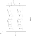
- FIG. 2 is a schematic diagram of another example compressor system 200.
- Compressor system 200 can have the same or a different configuration than compressor system 100.
- the example compressor system 200 resembles the example compressor system 100 in FIG. 1 except that FIG. 2 is directed towards an example discharge pressure control case whereas FIG. 1 is directed towards an example suction pressure control case.
- compressor system 200 includes two compressor trains 210, 250 in parallel and each of two trains 210, 250 including two compressors connect in series.
- the two compressor trains 210 and 250 share a common suction line 222 and a common discharge line 224.
- PT 225 is coupled to the discharge line 224 and is operable to measure the discharge header pressure.
- the first compressor train 210 includes two serial compressors 212 and 214, two control valves 216 and 218, and two PTs 213 and 215.
- the second compressor train 250 includes two serial compressors 252 and 254, two control valves 256 and 258, and two PTs 253 and 255.
- control valves 218 and 258 are primary control mechanisms. Primary control valves 218 and 258 are controlled by primary controllers that operate with a primary plant parameter, for example, discharge header pressure as measured by PT 225.
- Control valves 216 and 256 are secondary control valves controlled by secondary controllers that are responsible for serial load sharing within each compressor train. Similarly, the secondary controllers can include a performance controller and a cascaded serial load sharing controller.
- the intermediate pressure between the primary and secondary control mechanisms is determined and used as the process parameter for the performance controller.
- Other parameters such as motor current, distance from surge, pressure ratio, a bias calculated based on compressor work (e.g., calculated by an anti-surge logic), etc. may be used by serial load sharing control algorithms.
- the primary and secondary controller need to control process parameters that will not result in inverted reactions between the primary and secondary control mechanism. For instance, if the primary controller is controlling a pressure upstream of the primary control mechanism, such as a throttle valve, then the secondary controller may need to control pressure upstream of the control mechanism associated with the secondary control mechanism (e.g., as depicted in FIG. 1 ).
- the secondary controller may need to control pressure downstream of its control mechanism if the primary controller is controlling pressure downstream of the primary control mechanism (e.g., as depicted in FIG. 2 ).
- Such an arrangement can make the valves work consistently (i.e., they will move in the same direction when responding to a change in the primary control's process value or setpoint).
- a load sharing parameter can be determined for a load sharing controller.
- the load sharing controller can be cascaded to the performance controller associated with the control mechanism, to drive the setpoint of the performance controller.
- the load sharing parameter can include, but is not limited to, an operating point parameter (e.g., a distance from surge), a pressure ratio, (polytropic) head, external parameters, or other parameters.
- the performance controller included in the secondary controller can provide stable operation in response to setpoint and process changes, while the cascaded controller included in the secondary controller can ensure that both compressors operate, for example, at an approximately equal distance from surge.
- FIG. 3 is a block diagram illustrating example function blocks of a controller 300 that is operable to implement serial load sharing algorithms.
- Controller 300 can be used as the secondary controller for control valves 118, 158, 216, or 256 in FIGS. 1 and 2 , respectively, or in another manner.
- controller 300 can be used in a compressor system that only includes a single compressor train of multiple serial compressors.
- compressor 300 includes two controllers 330 and 370, wherein controller 330 is cascaded to controller 370.
- Controller 330 or 370 can be, for example, a proportional-integral-derivative (PID) controller, or another kind.
- Controller 330 can be a load sharing controller that operates with load sharing parameters (e.g., distance from surge, pressure ratio, etc.) while controller 370 can be a performance controller that operates with process variables (e.g., pressure, flow rate, etc.).
- load sharing parameters e.g., distance from surge, pressure ratio, etc.
- controller 370 can be a performance
- controller 330 receives load sharing setpoint 310 and load sharing parameter 320 as inputs.
- Controller 330 dynamically generates serial load sharing (SLS) outputs, for example, based on load sharing setpoint 310 and the load sharing parameters 320.
- SLS serial load sharing
- the SLS output, at 340, can be converted to a process performance setpoint (SP) for controller 370.
- SP process performance setpoint
- the conversion 340 of the SLS output to performance SP can be implemented as separate control logic from the controller 330 (e.g., as illustrated in FIG. 3 ), or the conversion 340 can be implemented as an integral component or module of the load sharing controller 330.
- controller 330 together with the conversion logic 340 is referred to as a load sharing controller, which determines process setpoint 350 for performance controller 370.
- Performance controller 370 receives process setpoint 350 driven by load sharing controller 330 and process control variable 360 and generates control output 380.
- Control output 380 can be sent to a control mechanism, for example, control valve 118, 158, 216, or 256 in FIGS. 1 and 2 , or another mechanism.
- the control mechanism for example, can fully or partially open or close to adjust the process variable and eventually realize serial load sharing among multiple serial compressors.
- the example techniques described herein use a load sharing controller to drive the process setpoint of the performance controller based on the load sharing parameters.
- the example techniques described herein can provide, in certain instances, a more complete control over the process and can often obtain more reliable and stable load sharing control.
- FIG. 3 can include additional or different function blocks.
- a manual valve controller may be included to allow manual adjustment or intervention.
- the outputs of the manual valve controller and performance controller 370 can be compared or otherwise manipulated by additional control logic (e.g., a performance low signal select, a filter, etc.). Then the selected or otherwise manipulated output from the additional control logic can be sent to the control mechanism for load sharing control.
- additional control logic e.g., a performance low signal select, a filter, etc.
- Other function blocks can be added and these and other function blocks can be configured in a different manner.
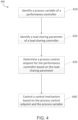
- FIG. 4 is a flow chart showing an example process 400 for controlling load sharing of compressors in series. All or part of the example process 400 may be implemented in hardware, software, firmware, or a combination thereof. In some instances, the example process 400 can be implemented as an example serial load sharing control algorithm for a compressor system including multiple compressors connected in series. The compressor system can include two or more compressor trains, for example, as shown in FIGS. 1 and 2 , or the compressor system can include a single compressor train with multiple serial compressors. As an example, the example process 400 can be implemented as serial load sharing control algorithms for controlling one or more of control valves 118, 158, 216, or 256 shown in FIGS. 1 and 2 .
- the example process 400 may be performed, for example, by any other suitable data processing apparatus, system, software, and hardware, or a combination thereof.
- the process 400, individual operations of the process 400, or groups of operations may be iterated or performed in parallel, in series, or in another manner.
- the process 400 may include the same, additional, fewer, or different operations performed in the same or different order.
- a process variable (e.g., process control parameter 360) of a performance controller (e.g., performance controller 370) can be identified.
- the intermediate pressure between the primary and secondary control mechanisms is identified as the process variable for the performance controller.
- the performance controller may be referred to as a pressure controller.
- identifying the process variable can include receiving measurement data or otherwise monitoring the process variable, for example, via measurement equipment (e.g., a pressure transceiver, temperature transceiver, sensor in the field, etc.).
- identifying the process variable can include monitoring the process variables in real time during the operation of the compressor system.
- a compressor system or a compressor train can include additional control mechanisms.
- the control mechanism responsible for serial load sharing is a secondary control mechanism while the compressor train further comprises a primary control mechanism.
- the performance controller is configured to control the secondary control mechanism such that the secondary control mechanism and the primary control mechanism operate consistently in response to a change in a process variable or a setpoint of the primary control mechanism.
- the process variable of the performance controller can be an intermediate pressure measured between the first control mechanism and the second control mechanism.
- Controller B can implement the example process 400, for example, to balance or otherwise manage the loads of compressors 112 and 114 while working with, not against, the needs of controller A.
- controller B can control a pressure upstream of the control valve 118, since controller A is controlling the upstream suction pressure.
- the intermediate pressure between control valves 116 and 118 measured by either PT 113 or 115, can be used as the process variable for the controller B.
- the discharge PT 115 from compressor 112 can be identified as the process variable of the controller B.
- the performance controller associated with the secondary control valve 216 can perform the example serial load sharing algorithm 400 and use intermediate pressure (e.g., measured by PT 213 or 215) that is downstream of secondary control valve 216.
- intermediate pressure e.g., measured by PT 213 or 215.
- additional or different downstream pressures can be used as the process variable for the performance controller of the secondary control valve 216.
- a load sharing parameter (e.g., load sharing parameter 320) of a load sharing controller (e.g., load sharing controller 330) can be identified.
- the load sharing parameter can include, for example, a distance from surge, a pressure ratio, a motor current, a turbine steam consumption, a calculated compressor power (a load value in watts), or other parameters.
- any measure of prime mover load can be used as the load sharing parameter. For example, if the prime mover is a motor then motor current could be used, or if the prime mover is a steam turbine, steam flow/consumption could be used.
- the load sharing parameter can be used to determine a load sharing process variable for the load sharing controller.
- a surge process variable can be identified as the load sharing parameter for the load sharing controller.
- the SPV can be a distance from surge that indicates the distance between the current operating point and the surge line.
- the surge line can be a collection of surge points on a compressor map. Above the surge line is a region of unstable flow, which is usually avoided.
- the SPV can be a process variable parameter used by an anti-surge controller to control the anti-surge valve.
- SPV is a value calculated based on compressor flow, suction pressure, discharge pressure, as well as temperatures.
- pressure ratio can be identified as the load sharing parameter for the load sharing controller.
- the pressure ratio can be, for example, a ratio of a discharge pressure to a suction pressure of a compressor, or the pressure ratio can be defined in another manner.
- the load sharing process variable for the load sharing controller can be the ratio of "pressure ratios." For example, if p2A/p1A and p2B/plB are the pressure ratios for compressor A and B respectively, then (p2B/p1B) / (p2A/p1A), i.e., the pressure ratio of compressor B divided by the pressure ratio of compressor A can be used as the load sharing process variable of the cascaded load sharing controller.
- the load sharing controller (e.g., load sharing controller 330) further identifies a load sharing setpoint (e.g., load sharing setpoint 310).
- the load sharing setpoint can be a desirable operating point for serial load sharing control.
- the load sharing setpoint can be specified or adjusted (e.g., manually or automatically) based on system requirements, process conditions, or other factors.
- the load sharing setpoint can be a value (e.g., "1") that indicates a balanced load distribution between two or more compressors.
- the load sharing setpoint can be another value.
- the load sharing setpoint can be specified (e.g., by an operator) to be a certain value so that the compressors operate at a particular imbalance of pressure ratios or SPV's, etc.
- a process control setpoint for the process variable of the performance controller can be determined dynamically based on the load sharing parameter by the load sharing controller (e.g., load sharing controller 330 and the SLS to SP conversion 340).
- the process control setpoint can be converted from a load sharing output that is determined based on the load sharing parameter and the load sharing setpoint of the load sharing controller.
- the load sharing process variable, the load sharing setpoint, or both can vary during the operation of the compressor system.
- the load sharing output, and thus the process control setpoint can be determined dynamically in response to a change of the load sharing process variable, the load sharing setpoint, or both.
- the cascaded load sharing controller is dynamically driving the setpoint for the performance controller during operation of the compressors.
- an exact setpoint for the process variable e.g., pressure
- a range of process control setpoints can be driven by the cascaded load sharing controller. These ranges can be configured and tuned as needed for best performance, for example, based on a rated condition given in compressor data sheets.
- the output of the cascaded controller is converted into a pressure setpoint range, which allows the performance controller to adjust the process variable while maintaining a desirable load sharing process variable.
- the cascaded load sharing controller calculates an output signal of 0-100%.
- This percentage can be converted into a setpoint for the performance controller that operates on, for example, pressure.
- the conversion is done by linearly scaling 0 to 100% of the load sharing controller output to some minimum and maximum pressure values.
- the rated pressure may be around 700 PSI.
- values of 500 and 900 PSI may be chosen as the minimum and maximum pressures for the pressure setpoint conversion.
- the pressure range 500-900 PSI is then the moving setpoint for the performance controller based on the load sharing parameter from the cascaded load sharing controller.
- the chosen range is just outside of the specification from the anti-surge pressure tables provided for Compressor A, which show surge occurs at approximately 550 PSI and choke occurs at approximately 800 PSI.
- the surge and choke limits from the anti-surge pressure tables could also be chosen as the serial load sharing pressure range limits, and the effects on the process and load sharing performance can be observed. Additional or different values can be specified as the minimum and maximum pressures.
- the minimum and maximum values for serial load sharing could also be set to be smaller or larger than the range specified in the compressor pressure tables.
- a wider range would allow the cascaded load sharing controller to drive the performance controller faster and farther to achieve the load sharing goals. A smaller range would result in more stable pressure control in the train, and possibly less process upset.
- a control mechanism can be controlled based on the process control setpoint and the process variable.
- the control mechanism can include one or more of a control valve, a speed controller, an inlet guide vane, or another control means.
- the control mechanism can receive a control signal from the performance controller and respond (e.g., partially or fully open or close) according to the control signal.
- the performance controller can compare its process control setpoint (e.g., determined based on the load sharing parameter at 430) and process variable and determine the output to control the control mechanism based on the comparison. For instance, using the same SPV example described above, given that a load sharing a setpoint is 1and a current load sharing process value is 1.05, the load sharing controller will decrease its output.
- the decrease of the load sharing controller output will result in a decrease of the process control setpoint (e.g., a pressure setpoint) of the performance controller.
- the load sharing controller can be referred to as a non-inverted controller.
- the performance controller Upon decrease of the pressure setpoint, assuming that the performance controller process value is higher than the pressure setpoint, the performance controller will increase its output since the performance controller is an upstream pressure controller (e.g., performance controller for control valve 118 or 158 in FIG. 1 ).
- the valve can open to decrease the upstream pressure.
- the performance controller is an inverted controller.
- for discharge pressure control e.g., as shown in FIG.
- valve e.g., control valve 216 or 256
- the inversion of performance controller and load sharing controller may be different.
- Some embodiments of subject matter and operations described in this specification can be implemented in digital electronic circuitry, or in computer software, firmware, or hardware, including the structures disclosed in this specification and their structural equivalents, or in combinations of one or more of them.
- Some embodiments of subject matter described in this specification can be implemented as one or more computer programs, i.e., one or more modules of computer program instructions, encoded on computer storage medium for execution by, or to control the operation of, data processing apparatus.
- a computer storage medium can be, or can be included in, a computer-readable storage device, a computer-readable storage substrate, a random or serial access memory array or device, or a combination of one or more of them.
- a computer storage medium is not a propagated signal
- a computer storage medium can be a source or destination of computer program instructions encoded in an artificially generated propagated signal.
- the computer storage medium can also be, or be included in, one or more separate physical components or media (e.g., multiple CDs, disks, or other storage devices).
- the term "data processing apparatus” encompasses all kinds of apparatus, devices, and machines for processing data, including by way of example a programmable processor, a computer, a system on a chip, or multiple ones, or combinations, of the foregoing.
- the apparatus can include special purpose logic circuitry, e.g., an FPGA (field programmable gate array) or an ASIC (application specific integrated circuit).
- the apparatus can also include, in addition to hardware, code that creates an execution environment for the computer program in question, e.g., code that constitutes processor firmware, a protocol stack, a database management system, an operating system, a cross-platform runtime environment, a virtual machine, or a combination of one or more of them.
- the apparatus and execution environment can realize various different computing model infrastructures, such as web services, distributed computing and grid computing infrastructures.
- a computer program (also known as a program, software, software application, script, or code) can be written in any form of programming language, including compiled or interpreted languages, declarative or procedural languages.
- a computer program may, but need not, correspond to a file in a file system.
- a program can be stored in a portion of a file that holds other programs or data (e.g., one or more scripts stored in a markup language document), in a single file dedicated to the program in question, or in multiple coordinated files (e.g., files that store one or more modules, sub programs, or portions of code).
- a computer program can be deployed to be executed on one computer or on multiple computers that are located at one site or distributed across multiple sites and interconnected by a communication network.
- Some of the processes and logic flows described in this specification can be performed by one or more programmable processors executing one or more computer programs to perform actions by operating on input data and generating output.
- the processes and logic flows can also be performed by, and apparatus can also be implemented as, special purpose logic circuitry, e.g., an FPGA (field programmable gate array) or an ASIC (application specific integrated circuit).
- processors suitable for the execution of a computer program include, by way of example, both general and special purpose microprocessors, and processors of any kind of digital computer.
- a processor will receive instructions and data from a read only memory or a random access memory or both.
- a computer includes a processor for performing actions in accordance with instructions and one or more memory devices for storing instructions and data.
- a computer may also include, or be operatively coupled to receive data from or transfer data to, or both, one or more mass storage devices for storing data, e.g., magnetic, magneto optical disks, or optical disks.
- mass storage devices for storing data, e.g., magnetic, magneto optical disks, or optical disks.
- a computer need not have such devices.
- Devices suitable for storing computer program instructions and data include all forms of non-volatile memory, media and memory devices, including by way of example semiconductor memory devices (e.g., EPROM, EEPROM, flash memory devices, and others), magnetic disks (e.g., internal hard disks, removable disks, and others), magneto optical disks , and CD ROM and DVD-ROM disks.
- semiconductor memory devices e.g., EPROM, EEPROM, flash memory devices, and others
- magnetic disks e.g., internal hard disks, removable disks, and others
- magneto optical disks e.g., CD ROM and DVD-ROM disks.
- the processor and the memory can be supplemented by, or incorporated in, special purpose logic circuitry.
- a computer having a display device (e.g., a monitor, or another type of display device) for displaying information to the user and a keyboard and a pointing device (e.g., a mouse, a trackball, a tablet, a touch sensitive screen, or another type of pointing device) by which the user can provide input to the computer.
- a display device e.g., a monitor, or another type of display device
- a keyboard and a pointing device e.g., a mouse, a trackball, a tablet, a touch sensitive screen, or another type of pointing device
- Other kinds of devices can be used to provide for interaction with a user as well; for example, feedback provided to the user can be any form of sensory feedback, e.g., visual feedback, auditory feedback, or tactile feedback; and input from the user can be received in any form, including acoustic, speech, or tactile input.
- a computer can interact with a user by sending documents to and receiving documents from a device that is used
- a client and server are generally remote from each other and typically interact through a communication network.
- Examples of communication networks include a local area network ("LAN”) and a wide area network (“WAN”), an inter-network (e.g., the Internet), a network comprising a satellite link, and peer-to-peer networks (e.g., ad hoc peer-to-peer networks).
- LAN local area network
- WAN wide area network
- inter-network e.g., the Internet
- peer-to-peer networks e.g., ad hoc peer-to-peer networks.
Landscapes
- Engineering & Computer Science (AREA)
- General Engineering & Computer Science (AREA)
- Mechanical Engineering (AREA)
- Physics & Mathematics (AREA)
- Geometry (AREA)
- General Physics & Mathematics (AREA)
- Automation & Control Theory (AREA)
- Control Of Positive-Displacement Air Blowers (AREA)
- Control Of Positive-Displacement Pumps (AREA)
Claims (9)
- Kompressorsystem, Folgendes umfassend:
einen Kompressorstrang (100, 200), der Folgendes beinhaltet:zwei oder mehr Kompressoren (112, 114, 152, 154), die in Reihe geschaltet sind,ein Steuersystem, das eine primäre Steuerung, eine Leistungssteuerung und eine Lastverteilungssteuerung umfasst,einen primären Steuermechanismus (116, 156, 218, 258), der von der primären Steuerung gesteuert wird, die mit einem primären Anlagenparameter arbeitet,einen Druckwandler (113, 115, 153, 155, 213, 215, 253, 255) undeinen sekundären Steuermechanismus (118, 158, 216, 256), der die Leistungssteuerung und die Lastverteilungssteuerung beinhaltet, wobei die Lastverteilungssteuerung der Leistungssteuerung nachgeschaltet ist und verwendet wird, um einen Einstellpunkt der Leistungssteuerung anzusteuern, wobei der sekundäre Steuermechanismus durch die Leistungssteuerung derart gesteuert wird, dass der sekundäre Steuermechanismus und der primäre Steuermechanismus in Reaktion einer Veränderung einer Prozessvariablen oder eines Einstellpunktes des primären Steuermechanismus gleichbleibend arbeiten, wobei der primäre und der sekundäre Steuermechanismus mit den zwei oder mehr Kompressoren gekoppelt sind, wobei die Leistungssteuerung für Folgendes funktionsfähig ist:Identifizieren einer Prozessvariablen der Leistungssteuerung, wobei die Prozessvariable der Leistungssteuerung ein Zwischendruck ist, der von dem Druckwandler zwischen dem primären Steuermechanismus und dem sekundären Steuermechanismus gemessen wird,Empfangen eines Einstellpunktes für die Prozessvariable der Leistungssteuerung auf einer wiederkehrenden Basis von der Lastverteilungssteuerung, wobei der Einstellungspunkt während des Betriebes der zwei oder mehr Kompressoren durch die Lastverteilungssteuerung basierend auf einem Lastverteilungsparameter, der mit den zwei Kompressoren in Verbindung steht, dynamisch bestimmt wird, undSteuern des sekundären Steuermechanismus basierend auf dem Einstellpunkt und der Prozessvariablen der Leistungssteuerung. - Kompressorsystem nach Anspruch 1, wobei der sekundäre Steuermechanismus eines oder mehrere eines Steuerventils (118, 158, 216, 256) eines Drehzahlreglers und einer Einlassleitschaufel umfasst.
- Kompressorsystem nach einem der vorhergehenden Ansprüche, wobei der Lastverteilungsparameter eines von einem Abstand zum Überdruck, einem Druckverhältnis, einem Motorstrom und einem Turbinendampfverbrauch ist.
- Kompressorsystem nach Anspruch 1, wobei der Kompressorstrang ein erster Kompressorstrang ist, ferner einen oder mehrere zusätzliche Kompressorstränge umfassend, wobei der eine oder die mehreren zusätzlichen Kompressorstränge und der erste Kompressorstran parallel geschaltet sind, wobei der primäre Steuermechanismus des ersten Kompressorstrangs paralleler Lastverteilung zwischen dem ersten Kompressorstrang und dem einen oder den mehreren zusätzlichen Kompressorsträngen unterliegt.
- Lastverteilungsverfahren für ein Kompressorsystem, wobei das Kompressorsystem zwei oder mehr Kompressoren (112, 114, 152, 154), die in Reihe geschaltet sind, einen primären Steuermechanismus (116, 156, 218, 258), der von einer primären Steuerung gesteuert wird, die mit einem primären Anlagenparameter arbeitet, einen Druckwandler (113, 115, 153, 155, 213, 215, 253, 255) und einen sekundären Steuermechanismus (118, 158, 216, 256) umfasst, der eine sekundäre Leistungssteuerung und eine Lastverteilungssteuerung beinhaltet, wobei die Lastverteilungssteuerung der sekundären Leistungssteuerung nachgeschaltet ist und verwendet wird, um einen Einstellpunkt der sekundären Leistungssteuerung anzusteuern, wobei der primäre und der sekundäre Steuermechanismus mit den zwei oder mehr Kompressoren gekoppelt sind, wobei das Verfahren Folgendes umfasst:Steuern des primären Steuermechanismus basierend auf dem primären Anlagenparameter,Identifizieren (410) einer Prozessvariablen der sekundären Leistungssteuerung, wobei die Prozessvariable der sekundären Leistungssteuerung ein Zwischendruck ist, der von dem Druckwandler zwischen dem primären Steuermechanismus und dem sekundären Steuermechanismus gemessen wird,Identifizieren (420) eines Lastverteilungsparameters der Lastverteilungssteuerung,dynamisches Bestimmen (430) eines Einstellpunktes der Prozesssteuerung für die Prozessvariable der sekundären Leistungssteuerung basierend auf dem Lastverteilungsparameter während des Betriebes der zwei oder mehr Kompressoren durch die Lastverteilungssteuerung undSteuern (440) des sekundären Steuermechanismus basierend auf dem Einstellpunkt der Prozesssteuerung und der Prozessvariablen derart, dass er gleichbleibend mit dem primären Steuermechanismus arbeitet, der von einer primären Leistungssteuerung gesteuert wird.
- Verfahren nach Anspruch 5, wobei das dynamische Bestimmen des Einstellpunktes der Prozesssteuerung für die Prozessvariable der sekundären Leistungssteuerung während des Betriebes der zwei oder mehr Kompressoren Folgendes umfasst:Identifizieren eines Einstellungspunktes der Lastverteilung für den Lastverteilungsparameter unddynamisches Bestimmen des Einstellpunktes der Prozesssteuerung für die Prozessvariable für die sekundäre Leistungssteuerung während des Betriebes der zwei oder mehr Kompressoren durch die Lastverteilungssteuerung, basierend auf dem Lastverteilungsparameter und dem Einstellungspunkt der Lastverteilung.
- Verfahren nach Anspruch 5 oder 6, wobei das Identifizieren des Lastverteilungsparameters Folgendes umfasst:Identifizieren des Lastverteilungsparameters als einen Abstand zum Überdruck,Bestimmen von Abständen zum Überdruck der zwei oder mehr Kompressoren undÜberwachen der Abstände zum Überdruck der zwei Kompressoren, und wobei das Steuern des zweiten Steuermechanismus basierend auf dem Einstellpunkt der Prozesssteuerung und der Prozessvariablen optional das Steuern des Steuermechanismus derart umfasst, dass die zwei oder mehr Kompressoren bei einem gleichen Abstand zum Überdruck gehalten werden.
- Verfahren nach Anspruch 5 oder 6, wobei das Identifizieren des Lastverteilungsparameters Folgendes umfasst:Identifizieren des Lastverteilungsparameters als ein Druckverhältnis der zwei oder mehr Kompressoren undÜberwachen des Druckverhältnisses der zwei oder mehr Kompressoren.
- Nicht-flüchtiges computerlesbares Medium, das Anweisungen speichert, die bei Ausführung in einem Steuersystem des Kompressorsystems nach einem der Ansprüche 1 bis 4 das Verfahren nach einem der Ansprüche 5 bis 8 ausführen.
Applications Claiming Priority (2)
| Application Number | Priority Date | Filing Date | Title |
|---|---|---|---|
| US14/089,471 US9695834B2 (en) | 2013-11-25 | 2013-11-25 | Load sharing control for compressors in series |
| PCT/US2014/066306 WO2015077282A1 (en) | 2013-11-25 | 2014-11-19 | Load sharing control for compressors in series |
Publications (2)
| Publication Number | Publication Date |
|---|---|
| EP3074637A1 EP3074637A1 (de) | 2016-10-05 |
| EP3074637B1 true EP3074637B1 (de) | 2023-08-02 |
Family
ID=52011326
Family Applications (1)
| Application Number | Title | Priority Date | Filing Date |
|---|---|---|---|
| EP14808786.9A Active EP3074637B1 (de) | 2013-11-25 | 2014-11-19 | Lastverteilungssteuerung für kompressoren in reihe |
Country Status (4)
| Country | Link |
|---|---|
| US (2) | US9695834B2 (de) |
| EP (1) | EP3074637B1 (de) |
| CN (1) | CN105917122B (de) |
| WO (1) | WO2015077282A1 (de) |
Families Citing this family (13)
| Publication number | Priority date | Publication date | Assignee | Title |
|---|---|---|---|---|
| EP3415758B1 (de) * | 2016-02-09 | 2019-06-05 | Mitsubishi Heavy Industries Compressor Corporation | Verstärkersystem |
| RU2016112469A (ru) | 2016-04-01 | 2017-10-04 | Фишер-Роузмаунт Системз, Инк. | Способы и устройство для обнаружения и предотвращения помпажа компрессора |
| CN107829969B (zh) * | 2017-07-31 | 2020-12-08 | 青岛海尔空调电子有限公司 | 一种磁悬浮离心式空调机组防喘振控制方法及系统 |
| CN108708872B (zh) * | 2018-04-26 | 2019-10-11 | 西安交通大学 | 一种并列运行透平压缩机控制方法及控制系统 |
| US12241426B2 (en) | 2019-01-03 | 2025-03-04 | General Electric Company | Systems and methods of controlling load share and speed of engines in multiple-engine propulsion systems |
| US11408418B2 (en) * | 2019-08-13 | 2022-08-09 | Rockwell Automation Technologies, Inc. | Industrial control system for distributed compressors |
| WO2021161133A1 (en) * | 2020-02-10 | 2021-08-19 | Khalifa University of Science and Technology | An apparatus for optimal loadsharing between parallel gas compressors |
| CN112610522B (zh) * | 2020-12-31 | 2023-01-24 | 浙江中控技术股份有限公司 | 一种串联压缩机组的控制方法和相关设备 |
| CN114278603B (zh) * | 2021-12-27 | 2024-05-14 | 中控技术股份有限公司 | 一种压缩机控制系统、方法、装置、设备及存储介质 |
| US11920521B2 (en) | 2022-02-07 | 2024-03-05 | General Electric Company | Turboshaft load control using feedforward and feedback control |
| US12442369B2 (en) * | 2022-08-12 | 2025-10-14 | Air Products And Chemicals, Inc. | Method and system for load control of reciprocating compressors |
| CN116733769A (zh) * | 2023-07-03 | 2023-09-12 | 西安陕鼓动力股份有限公司 | 用于串联压缩机组的负荷分配控制方法 |
| CN119962237A (zh) * | 2025-02-06 | 2025-05-09 | 哈尔滨汽轮机厂有限责任公司 | 三级串联压缩机仿真数据获取方法 |
Citations (1)
| Publication number | Priority date | Publication date | Assignee | Title |
|---|---|---|---|---|
| US20030063981A1 (en) * | 2001-10-01 | 2003-04-03 | Dresser-Rand Company | Management and optimization of load sharing between multiple compressor trains for controlling a main process gas variable |
Family Cites Families (17)
| Publication number | Priority date | Publication date | Assignee | Title |
|---|---|---|---|---|
| US4940391A (en) * | 1988-11-07 | 1990-07-10 | Westinghouse Electric Corp. | Compressor surge detection system |
| FR2666854B1 (fr) * | 1990-09-19 | 1992-12-18 | Framatome Sa | Dispositif de commande de moyens d'antipompage d'un compresseur. |
| US5306116A (en) * | 1992-04-10 | 1994-04-26 | Ingersoll-Rand Company | Surge control and recovery for a centrifugal compressor |
| US5347467A (en) * | 1992-06-22 | 1994-09-13 | Compressor Controls Corporation | Load sharing method and apparatus for controlling a main gas parameter of a compressor station with multiple dynamic compressors |
| US5343384A (en) | 1992-10-13 | 1994-08-30 | Ingersoll-Rand Company | Method and apparatus for controlling a system of compressors to achieve load sharing |
| US5743715A (en) | 1995-10-20 | 1998-04-28 | Compressor Controls Corporation | Method and apparatus for load balancing among multiple compressors |
| US5743714A (en) | 1996-04-03 | 1998-04-28 | Dmitry Drob | Method and apparatus for minimum work control optimization of multicompressor stations |
| JP2000120583A (ja) * | 1998-10-14 | 2000-04-25 | Kobe Steel Ltd | 圧縮機制御方法及びその装置 |
| JP3751208B2 (ja) * | 2001-02-23 | 2006-03-01 | 株式会社神戸製鋼所 | 多段可変速圧縮機の制御方法 |
| JP3741014B2 (ja) * | 2001-09-18 | 2006-02-01 | 株式会社日立製作所 | 複数台の圧縮機の制御方法及び圧縮機システム |
| WO2004013494A1 (en) * | 2002-08-06 | 2004-02-12 | York International Corporation | Stability control system and method for centrifugal compressors operating in parallel |
| BE1015460A3 (nl) * | 2003-04-04 | 2005-04-05 | Atlas Copco Airpower Nv | Werkwijze voor het sturen van een persluchtinstallatie met meerdere compressoren, stuurdoos daarbij toegepast, en persluchtinstallatie die deze werkwijze toepast. |
| DE102005006410A1 (de) | 2005-02-11 | 2006-08-17 | Siemens Ag | Verfahren zur Optimierung des Betriebs mehrerer Verdichteraggregate und Vorrichtung hierzu |
| US8360744B2 (en) * | 2008-03-13 | 2013-01-29 | Compressor Controls Corporation | Compressor-expander set critical speed avoidance |
| US8323000B2 (en) | 2008-06-23 | 2012-12-04 | Compressor Controls Corp. | Compressor-driver power limiting in consideration of antisurge control |
| RU128917U1 (ru) | 2012-10-25 | 2013-06-10 | Закрытое акционерное общество "ВО Машэкспорт" | Система управления компрессорной станцией магистрального газопровода |
| CN104885024B (zh) * | 2012-12-12 | 2017-10-13 | 塞阿姆斯特朗有限公司 | 经协调的无传感器控制系统 |
-
2013
- 2013-11-25 US US14/089,471 patent/US9695834B2/en active Active
-
2014
- 2014-11-19 CN CN201480073921.9A patent/CN105917122B/zh active Active
- 2014-11-19 WO PCT/US2014/066306 patent/WO2015077282A1/en not_active Ceased
- 2014-11-19 EP EP14808786.9A patent/EP3074637B1/de active Active
-
2017
- 2017-02-09 US US15/428,998 patent/US10400776B2/en active Active
Patent Citations (1)
| Publication number | Priority date | Publication date | Assignee | Title |
|---|---|---|---|---|
| US20030063981A1 (en) * | 2001-10-01 | 2003-04-03 | Dresser-Rand Company | Management and optimization of load sharing between multiple compressor trains for controlling a main process gas variable |
Also Published As
| Publication number | Publication date |
|---|---|
| WO2015077282A1 (en) | 2015-05-28 |
| US9695834B2 (en) | 2017-07-04 |
| CN105917122B (zh) | 2017-12-15 |
| US20150147193A1 (en) | 2015-05-28 |
| EP3074637A1 (de) | 2016-10-05 |
| CN105917122A (zh) | 2016-08-31 |
| US10400776B2 (en) | 2019-09-03 |
| US20170152856A1 (en) | 2017-06-01 |
Similar Documents
| Publication | Publication Date | Title |
|---|---|---|
| EP3074637B1 (de) | Lastverteilungssteuerung für kompressoren in reihe | |
| CN107820556B (zh) | 用于确定液压网络的特性参数的方法和系统 | |
| US9052703B2 (en) | Enhanced sequential method for solving pressure/flow network parameters in a real-time distributed industrial process simulation system | |
| US10738660B2 (en) | Generating steam turbine performance maps | |
| CN113728162B (zh) | 用于优化控制回路系统中马达驱动的装备的使用的电子设备及方法 | |
| CN103363746B (zh) | 蒸汽压缩系统的操作方法、工作控制方法和优化控制器 | |
| JP5833851B2 (ja) | グリッド周波数レート制限システム | |
| CN105209983A (zh) | 具有机械变量的模型预测控制的电驱动系统 | |
| Wang et al. | Prediction method for low speed characteristics of compressor based on modified similarity theory with genetic algorithm | |
| CN104884814A (zh) | 用于操作压缩机装置的系统和方法 | |
| EP3875774B1 (de) | Systeme, programmprodukte und verfahren zur einstellung des betriebsgrenzwerts (ol) für kompressoren von gasturbinensystemen basierend auf dem massenstromverlust | |
| AU2018270018B2 (en) | Boiler combustion control system and boiler combustion control method | |
| JP2017115867A (ja) | スケーリングファクタを用いてパワー出力/放出パラメータを調節するガスタービンにおける複合確率的制御、関連した制御システム、コンピュータプログラム製品、および方法 | |
| JP2017115871A (ja) | スケーリングファクタを用いてパワー出力/放出パラメータを調節するガスタービンにおける複合確率的制御の応用、関連した制御システム、コンピュータプログラム製品、および方法 | |
| Jones et al. | Distributed model predictive control of centrifugal compressor systems | |
| JP2017129121A (ja) | スケーリングファクタを用いてパワー出力/放出パラメータを調節するガスタービンにおける複合確率的制御の応用、関連した制御システム、コンピュータプログラム製品、および方法 | |
| CN114592973A (zh) | 燃气轮机可调静子叶片角度控制方法、系统、设备和介质 | |
| Gevorkov et al. | Study of the centrifugal pump efficiency at throttling and speed control | |
| CN106988893A (zh) | 在燃气轮机调节中对功率输出‑排放参数的概率控制 | |
| EP2901020B1 (de) | Verdichterprüfstand mit erzielung des druckverhältnisses durch drosselung | |
| Carrillo Peña et al. | Improving the performance of centrifugal pumps in serial and parallel configurations using digital twins | |
| Ismail Al Zawaideh et al. | Control-oriented modelling and optimal adaptive control of parallel compressors | |
| JP7071031B2 (ja) | 燃料消費量に基づいて電力システムを制御するための制御システムおよび関連するプログラム製品 | |
| CN121719651A (zh) | 应用于燃气轮机的运行控制方法、装置、设备和可读介质 | |
| Banyai et al. | Hydrostatic transmission for low power wind turbines |
Legal Events
| Date | Code | Title | Description |
|---|---|---|---|
| PUAI | Public reference made under article 153(3) epc to a published international application that has entered the european phase |
Free format text: ORIGINAL CODE: 0009012 |
|
| 17P | Request for examination filed |
Effective date: 20160613 |
|
| AK | Designated contracting states |
Kind code of ref document: A1 Designated state(s): AL AT BE BG CH CY CZ DE DK EE ES FI FR GB GR HR HU IE IS IT LI LT LU LV MC MK MT NL NO PL PT RO RS SE SI SK SM TR |
|
| AX | Request for extension of the european patent |
Extension state: BA ME |
|
| DAX | Request for extension of the european patent (deleted) | ||
| RAP1 | Party data changed (applicant data changed or rights of an application transferred) |
Owner name: WOODWARD, INC. |
|
| STAA | Information on the status of an ep patent application or granted ep patent |
Free format text: STATUS: EXAMINATION IS IN PROGRESS |
|
| 17Q | First examination report despatched |
Effective date: 20190625 |
|
| GRAP | Despatch of communication of intention to grant a patent |
Free format text: ORIGINAL CODE: EPIDOSNIGR1 |
|
| STAA | Information on the status of an ep patent application or granted ep patent |
Free format text: STATUS: GRANT OF PATENT IS INTENDED |
|
| INTG | Intention to grant announced |
Effective date: 20221123 |
|
| GRAJ | Information related to disapproval of communication of intention to grant by the applicant or resumption of examination proceedings by the epo deleted |
Free format text: ORIGINAL CODE: EPIDOSDIGR1 |
|
| STAA | Information on the status of an ep patent application or granted ep patent |
Free format text: STATUS: EXAMINATION IS IN PROGRESS |
|
| GRAP | Despatch of communication of intention to grant a patent |
Free format text: ORIGINAL CODE: EPIDOSNIGR1 |
|
| STAA | Information on the status of an ep patent application or granted ep patent |
Free format text: STATUS: GRANT OF PATENT IS INTENDED |
|
| INTC | Intention to grant announced (deleted) | ||
| INTG | Intention to grant announced |
Effective date: 20230321 |
|
| GRAS | Grant fee paid |
Free format text: ORIGINAL CODE: EPIDOSNIGR3 |
|
| GRAA | (expected) grant |
Free format text: ORIGINAL CODE: 0009210 |
|
| STAA | Information on the status of an ep patent application or granted ep patent |
Free format text: STATUS: THE PATENT HAS BEEN GRANTED |
|
| AK | Designated contracting states |
Kind code of ref document: B1 Designated state(s): AL AT BE BG CH CY CZ DE DK EE ES FI FR GB GR HR HU IE IS IT LI LT LU LV MC MK MT NL NO PL PT RO RS SE SI SK SM TR |
|
| REG | Reference to a national code |
Ref country code: GB Ref legal event code: FG4D |
|
| P01 | Opt-out of the competence of the unified patent court (upc) registered |
Effective date: 20230704 |
|
| REG | Reference to a national code |
Ref country code: CH Ref legal event code: EP |
|
| REG | Reference to a national code |
Ref country code: DE Ref legal event code: R096 Ref document number: 602014087842 Country of ref document: DE |
|
| REG | Reference to a national code |
Ref country code: IE Ref legal event code: FG4D |
|
| REG | Reference to a national code |
Ref country code: LT Ref legal event code: MG9D |
|
| REG | Reference to a national code |
Ref country code: NL Ref legal event code: MP Effective date: 20230802 |
|
| REG | Reference to a national code |
Ref country code: AT Ref legal event code: MK05 Ref document number: 1595047 Country of ref document: AT Kind code of ref document: T Effective date: 20230802 |
|
| PG25 | Lapsed in a contracting state [announced via postgrant information from national office to epo] |
Ref country code: GR Free format text: LAPSE BECAUSE OF FAILURE TO SUBMIT A TRANSLATION OF THE DESCRIPTION OR TO PAY THE FEE WITHIN THE PRESCRIBED TIME-LIMIT Effective date: 20231103 |
|
| PG25 | Lapsed in a contracting state [announced via postgrant information from national office to epo] |
Ref country code: IS Free format text: LAPSE BECAUSE OF FAILURE TO SUBMIT A TRANSLATION OF THE DESCRIPTION OR TO PAY THE FEE WITHIN THE PRESCRIBED TIME-LIMIT Effective date: 20231202 |
|
| PG25 | Lapsed in a contracting state [announced via postgrant information from national office to epo] |
Ref country code: SE Free format text: LAPSE BECAUSE OF FAILURE TO SUBMIT A TRANSLATION OF THE DESCRIPTION OR TO PAY THE FEE WITHIN THE PRESCRIBED TIME-LIMIT Effective date: 20230802 Ref country code: RS Free format text: LAPSE BECAUSE OF FAILURE TO SUBMIT A TRANSLATION OF THE DESCRIPTION OR TO PAY THE FEE WITHIN THE PRESCRIBED TIME-LIMIT Effective date: 20230802 Ref country code: PT Free format text: LAPSE BECAUSE OF FAILURE TO SUBMIT A TRANSLATION OF THE DESCRIPTION OR TO PAY THE FEE WITHIN THE PRESCRIBED TIME-LIMIT Effective date: 20231204 Ref country code: NO Free format text: LAPSE BECAUSE OF FAILURE TO SUBMIT A TRANSLATION OF THE DESCRIPTION OR TO PAY THE FEE WITHIN THE PRESCRIBED TIME-LIMIT Effective date: 20231102 Ref country code: NL Free format text: LAPSE BECAUSE OF FAILURE TO SUBMIT A TRANSLATION OF THE DESCRIPTION OR TO PAY THE FEE WITHIN THE PRESCRIBED TIME-LIMIT Effective date: 20230802 Ref country code: LV Free format text: LAPSE BECAUSE OF FAILURE TO SUBMIT A TRANSLATION OF THE DESCRIPTION OR TO PAY THE FEE WITHIN THE PRESCRIBED TIME-LIMIT Effective date: 20230802 Ref country code: LT Free format text: LAPSE BECAUSE OF FAILURE TO SUBMIT A TRANSLATION OF THE DESCRIPTION OR TO PAY THE FEE WITHIN THE PRESCRIBED TIME-LIMIT Effective date: 20230802 Ref country code: IS Free format text: LAPSE BECAUSE OF FAILURE TO SUBMIT A TRANSLATION OF THE DESCRIPTION OR TO PAY THE FEE WITHIN THE PRESCRIBED TIME-LIMIT Effective date: 20231202 Ref country code: HR Free format text: LAPSE BECAUSE OF FAILURE TO SUBMIT A TRANSLATION OF THE DESCRIPTION OR TO PAY THE FEE WITHIN THE PRESCRIBED TIME-LIMIT Effective date: 20230802 Ref country code: GR Free format text: LAPSE BECAUSE OF FAILURE TO SUBMIT A TRANSLATION OF THE DESCRIPTION OR TO PAY THE FEE WITHIN THE PRESCRIBED TIME-LIMIT Effective date: 20231103 Ref country code: FI Free format text: LAPSE BECAUSE OF FAILURE TO SUBMIT A TRANSLATION OF THE DESCRIPTION OR TO PAY THE FEE WITHIN THE PRESCRIBED TIME-LIMIT Effective date: 20230802 Ref country code: AT Free format text: LAPSE BECAUSE OF FAILURE TO SUBMIT A TRANSLATION OF THE DESCRIPTION OR TO PAY THE FEE WITHIN THE PRESCRIBED TIME-LIMIT Effective date: 20230802 |
|
| PG25 | Lapsed in a contracting state [announced via postgrant information from national office to epo] |
Ref country code: PL Free format text: LAPSE BECAUSE OF FAILURE TO SUBMIT A TRANSLATION OF THE DESCRIPTION OR TO PAY THE FEE WITHIN THE PRESCRIBED TIME-LIMIT Effective date: 20230802 |
|
| PG25 | Lapsed in a contracting state [announced via postgrant information from national office to epo] |
Ref country code: ES Free format text: LAPSE BECAUSE OF FAILURE TO SUBMIT A TRANSLATION OF THE DESCRIPTION OR TO PAY THE FEE WITHIN THE PRESCRIBED TIME-LIMIT Effective date: 20230802 |
|
| PG25 | Lapsed in a contracting state [announced via postgrant information from national office to epo] |
Ref country code: SM Free format text: LAPSE BECAUSE OF FAILURE TO SUBMIT A TRANSLATION OF THE DESCRIPTION OR TO PAY THE FEE WITHIN THE PRESCRIBED TIME-LIMIT Effective date: 20230802 Ref country code: RO Free format text: LAPSE BECAUSE OF FAILURE TO SUBMIT A TRANSLATION OF THE DESCRIPTION OR TO PAY THE FEE WITHIN THE PRESCRIBED TIME-LIMIT Effective date: 20230802 Ref country code: ES Free format text: LAPSE BECAUSE OF FAILURE TO SUBMIT A TRANSLATION OF THE DESCRIPTION OR TO PAY THE FEE WITHIN THE PRESCRIBED TIME-LIMIT Effective date: 20230802 Ref country code: EE Free format text: LAPSE BECAUSE OF FAILURE TO SUBMIT A TRANSLATION OF THE DESCRIPTION OR TO PAY THE FEE WITHIN THE PRESCRIBED TIME-LIMIT Effective date: 20230802 Ref country code: DK Free format text: LAPSE BECAUSE OF FAILURE TO SUBMIT A TRANSLATION OF THE DESCRIPTION OR TO PAY THE FEE WITHIN THE PRESCRIBED TIME-LIMIT Effective date: 20230802 Ref country code: CZ Free format text: LAPSE BECAUSE OF FAILURE TO SUBMIT A TRANSLATION OF THE DESCRIPTION OR TO PAY THE FEE WITHIN THE PRESCRIBED TIME-LIMIT Effective date: 20230802 Ref country code: SK Free format text: LAPSE BECAUSE OF FAILURE TO SUBMIT A TRANSLATION OF THE DESCRIPTION OR TO PAY THE FEE WITHIN THE PRESCRIBED TIME-LIMIT Effective date: 20230802 |
|
| REG | Reference to a national code |
Ref country code: DE Ref legal event code: R097 Ref document number: 602014087842 Country of ref document: DE |
|
| PG25 | Lapsed in a contracting state [announced via postgrant information from national office to epo] |
Ref country code: IT Free format text: LAPSE BECAUSE OF FAILURE TO SUBMIT A TRANSLATION OF THE DESCRIPTION OR TO PAY THE FEE WITHIN THE PRESCRIBED TIME-LIMIT Effective date: 20230802 |
|
| PLBE | No opposition filed within time limit |
Free format text: ORIGINAL CODE: 0009261 |
|
| STAA | Information on the status of an ep patent application or granted ep patent |
Free format text: STATUS: NO OPPOSITION FILED WITHIN TIME LIMIT |
|
| REG | Reference to a national code |
Ref country code: CH Ref legal event code: PL |
|
| PG25 | Lapsed in a contracting state [announced via postgrant information from national office to epo] |
Ref country code: MC Free format text: LAPSE BECAUSE OF FAILURE TO SUBMIT A TRANSLATION OF THE DESCRIPTION OR TO PAY THE FEE WITHIN THE PRESCRIBED TIME-LIMIT Effective date: 20230802 |
|
| 26N | No opposition filed |
Effective date: 20240503 |
|
| PG25 | Lapsed in a contracting state [announced via postgrant information from national office to epo] |
Ref country code: LU Free format text: LAPSE BECAUSE OF NON-PAYMENT OF DUE FEES Effective date: 20231119 |
|
| PG25 | Lapsed in a contracting state [announced via postgrant information from national office to epo] |
Ref country code: CH Free format text: LAPSE BECAUSE OF NON-PAYMENT OF DUE FEES Effective date: 20231130 |
|
| PG25 | Lapsed in a contracting state [announced via postgrant information from national office to epo] |
Ref country code: MC Free format text: LAPSE BECAUSE OF FAILURE TO SUBMIT A TRANSLATION OF THE DESCRIPTION OR TO PAY THE FEE WITHIN THE PRESCRIBED TIME-LIMIT Effective date: 20230802 Ref country code: LU Free format text: LAPSE BECAUSE OF NON-PAYMENT OF DUE FEES Effective date: 20231119 Ref country code: CH Free format text: LAPSE BECAUSE OF NON-PAYMENT OF DUE FEES Effective date: 20231130 Ref country code: SI Free format text: LAPSE BECAUSE OF FAILURE TO SUBMIT A TRANSLATION OF THE DESCRIPTION OR TO PAY THE FEE WITHIN THE PRESCRIBED TIME-LIMIT Effective date: 20230802 |
|
| REG | Reference to a national code |
Ref country code: BE Ref legal event code: MM Effective date: 20231130 |
|
| REG | Reference to a national code |
Ref country code: IE Ref legal event code: MM4A |
|
| PG25 | Lapsed in a contracting state [announced via postgrant information from national office to epo] |
Ref country code: IE Free format text: LAPSE BECAUSE OF NON-PAYMENT OF DUE FEES Effective date: 20231119 |
|
| PG25 | Lapsed in a contracting state [announced via postgrant information from national office to epo] |
Ref country code: BE Free format text: LAPSE BECAUSE OF NON-PAYMENT OF DUE FEES Effective date: 20231130 |
|
| PG25 | Lapsed in a contracting state [announced via postgrant information from national office to epo] |
Ref country code: FR Free format text: LAPSE BECAUSE OF NON-PAYMENT OF DUE FEES Effective date: 20231130 |
|
| PG25 | Lapsed in a contracting state [announced via postgrant information from national office to epo] |
Ref country code: IE Free format text: LAPSE BECAUSE OF NON-PAYMENT OF DUE FEES Effective date: 20231119 Ref country code: FR Free format text: LAPSE BECAUSE OF NON-PAYMENT OF DUE FEES Effective date: 20231130 Ref country code: BE Free format text: LAPSE BECAUSE OF NON-PAYMENT OF DUE FEES Effective date: 20231130 |
|
| PG25 | Lapsed in a contracting state [announced via postgrant information from national office to epo] |
Ref country code: BG Free format text: LAPSE BECAUSE OF FAILURE TO SUBMIT A TRANSLATION OF THE DESCRIPTION OR TO PAY THE FEE WITHIN THE PRESCRIBED TIME-LIMIT Effective date: 20230802 |
|
| PG25 | Lapsed in a contracting state [announced via postgrant information from national office to epo] |
Ref country code: BG Free format text: LAPSE BECAUSE OF FAILURE TO SUBMIT A TRANSLATION OF THE DESCRIPTION OR TO PAY THE FEE WITHIN THE PRESCRIBED TIME-LIMIT Effective date: 20230802 |
|
| PG25 | Lapsed in a contracting state [announced via postgrant information from national office to epo] |
Ref country code: CY Free format text: LAPSE BECAUSE OF FAILURE TO SUBMIT A TRANSLATION OF THE DESCRIPTION OR TO PAY THE FEE WITHIN THE PRESCRIBED TIME-LIMIT; INVALID AB INITIO Effective date: 20141119 |
|
| PG25 | Lapsed in a contracting state [announced via postgrant information from national office to epo] |
Ref country code: HU Free format text: LAPSE BECAUSE OF FAILURE TO SUBMIT A TRANSLATION OF THE DESCRIPTION OR TO PAY THE FEE WITHIN THE PRESCRIBED TIME-LIMIT; INVALID AB INITIO Effective date: 20141119 |
|
| PG25 | Lapsed in a contracting state [announced via postgrant information from national office to epo] |
Ref country code: TR Free format text: LAPSE BECAUSE OF FAILURE TO SUBMIT A TRANSLATION OF THE DESCRIPTION OR TO PAY THE FEE WITHIN THE PRESCRIBED TIME-LIMIT Effective date: 20230802 |
|
| PGFP | Annual fee paid to national office [announced via postgrant information from national office to epo] |
Ref country code: DE Payment date: 20251128 Year of fee payment: 12 |
|
| PGFP | Annual fee paid to national office [announced via postgrant information from national office to epo] |
Ref country code: GB Payment date: 20251127 Year of fee payment: 12 |