EP2333240B1 - Aube de turbine en deux parties avec des caractéristiques de refroidissement et de vibrations améliorées - Google Patents
Aube de turbine en deux parties avec des caractéristiques de refroidissement et de vibrations améliorées Download PDFInfo
- Publication number
- EP2333240B1 EP2333240B1 EP20090177829 EP09177829A EP2333240B1 EP 2333240 B1 EP2333240 B1 EP 2333240B1 EP 20090177829 EP20090177829 EP 20090177829 EP 09177829 A EP09177829 A EP 09177829A EP 2333240 B1 EP2333240 B1 EP 2333240B1
- Authority
- EP
- European Patent Office
- Prior art keywords
- blade
- airfoil
- previous
- blades
- portions
- Prior art date
- Legal status (The legal status is an assumption and is not a legal conclusion. Google has not performed a legal analysis and makes no representation as to the accuracy of the status listed.)
- Not-in-force
Links
Images


Classifications
-
- F—MECHANICAL ENGINEERING; LIGHTING; HEATING; WEAPONS; BLASTING
- F01—MACHINES OR ENGINES IN GENERAL; ENGINE PLANTS IN GENERAL; STEAM ENGINES
- F01D—NON-POSITIVE DISPLACEMENT MACHINES OR ENGINES, e.g. STEAM TURBINES
- F01D5/00—Blades; Blade-carrying members; Heating, heat-insulating, cooling or antivibration means on the blades or the members
- F01D5/12—Blades
- F01D5/14—Form or construction
- F01D5/141—Shape, i.e. outer, aerodynamic form
- F01D5/146—Shape, i.e. outer, aerodynamic form of blades with tandem configuration, split blades or slotted blades
-
- F—MECHANICAL ENGINEERING; LIGHTING; HEATING; WEAPONS; BLASTING
- F01—MACHINES OR ENGINES IN GENERAL; ENGINE PLANTS IN GENERAL; STEAM ENGINES
- F01D—NON-POSITIVE DISPLACEMENT MACHINES OR ENGINES, e.g. STEAM TURBINES
- F01D5/00—Blades; Blade-carrying members; Heating, heat-insulating, cooling or antivibration means on the blades or the members
- F01D5/12—Blades
- F01D5/14—Form or construction
- F01D5/147—Construction, i.e. structural features, e.g. of weight-saving hollow blades
-
- F—MECHANICAL ENGINEERING; LIGHTING; HEATING; WEAPONS; BLASTING
- F01—MACHINES OR ENGINES IN GENERAL; ENGINE PLANTS IN GENERAL; STEAM ENGINES
- F01D—NON-POSITIVE DISPLACEMENT MACHINES OR ENGINES, e.g. STEAM TURBINES
- F01D5/00—Blades; Blade-carrying members; Heating, heat-insulating, cooling or antivibration means on the blades or the members
- F01D5/12—Blades
- F01D5/14—Form or construction
- F01D5/18—Hollow blades, i.e. blades with cooling or heating channels or cavities; Heating, heat-insulating or cooling means on blades
- F01D5/187—Convection cooling
- F01D5/188—Convection cooling with an insert in the blade cavity to guide the cooling fluid, e.g. forming a separation wall
- F01D5/189—Convection cooling with an insert in the blade cavity to guide the cooling fluid, e.g. forming a separation wall the insert having a tubular cross-section, e.g. airfoil shape
Definitions
- the present invention relates to a turbine blade.
- the turbine blade of the present invention may be a rotor blade and/or a guide vane (i.e. stator blade) of a gas turbine or a steam turbine.
- Turbine rotor blades of gas turbines are known to comprise a platform having a root with typically a dovetail/fir tree shape to be connected to a corresponding seat of a blade carrier.
- an airfoil extends, shaped with a pressure side and a suction side arranged to cooperate with hot gases that pass through the turbine.
- the turbine rotor blades When assembled on the blade carrier, the turbine rotor blades are all arranged one adjacent to the other, such that their platforms define the inner surface of the annular hot gases path.
- Blades have usually a number of internal cooling channels through which, during operation, cooling air is driven.
- blades are usually manufactured by casting them with an internal ceramic core forming the cooling channels.
- This casting technique is very expensive and time consuming; in addition the channels (formed in the ceramic core) usually are not provided with all ideal features from the cooling point of view, but they are optimised for making the manufacturing process easier and cheaper.
- the cooling channels could not provide an efficient cooling, such that during operation overheating and difficult cooling could become a problem.
- WO 00/53895 discloses blades having a platform and a root. From the opposite circumferential sides of the platform airfoil portions (namely a front and a rear airfoil portions) extend.
- US 2,930,580 discloses airfoils made of a plurality of pieces of the same blade.
- the technical aim of the present invention is therefore to provide a blade and a corresponding blade arrangement by which the said problems of the known art are eliminated.
- an aspect of the invention is to provide a blade with which the purge air injected into the hot gases path may be reduced with respect to the air needed with traditional blades, thus achieving an efficiency increase.
- Another aspect of the invention is to provide a blade which lets heat transfer enhancers (such as for example inner cooling channels or fins) of each airfoil be easily manufactured with costs lower than those needed for corresponding traditional blades and in a time effective way.
- heat transfer enhancers such as for example inner cooling channels or fins
- a further aspect of the invention is to manufacture optimised heat transfer enhancers, i.e. heat transfer enhancers whose structure and shape is mainly defined by the desired cooling effect instead of manufacturing constrains.
- a rotor blade of a gas turbine In the following reference to a rotor blade of a gas turbine will be made; it is anyhow clear that in different embodiments of the invention the blade could also be a guide vane of a gas turbine or in even further embodiments also a rotor or stator blade of a steam turbine or different rotating machine.
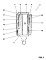
- a turbine blade 1 comprising a platform 2 provided with a root 3 arranged to be connected to a blade carrier (not shown in figure 1 but indicated by 22 in figure 5 ).
- airfoil portions 5, 6 extend.
- Each airfoil portion defines one operating surface 7, 8 being the surface facing the other airfoil portion.
- the surface 8 of the airfoil portion 6 that faces the other airfoil portion 5 of the same blade 1 is an operating surface of the blade 1, i.e. a surface that, when the blade is assembled in a gas turbine and during operation of the same gas turbine is arranged to come into contact with the hot gases flowing into the hot gases path.
- figure 2 shows the operating surface 7 of the airfoil portion 5 being the surface of the airfoil 5 facing the other airfoil portion 6 of the same blade 1 and arranged to come into contact with the hot gases during operation.
- the operating surface 7 of the airfoil portions 5 defines a suction side and the operating surface 8 of the airfoil portion 6 defines a pressure side of airfoils to be defined when a number of blades 1 are connected each other.
- the blade 1 also comprises a shroud 10 connected at the ends of each airfoil portion 5 and 6, such that the platform 2 with the airfoil portions 5 and 6 and the shroud 10 define a closed channel 11.
- the surfaces 14, 15 of the airfoil portions 5, 6 opposite the operating surfaces 7, 8 define inner surfaces of airfoils that, when a number of blades are assembled on a blade carrier, are defined by two adjacent airfoil portions; these inner surfaces 14, 15 do not come into contact with the hot gases during normal operation of the gas turbine.
- these inner surfaces 14 and 15 are directly accessible for the operators and manufacturing tools, they can be shaped according to the needs in a very easy and fast way, with traditional tools and at limited costs; in other words shaping of these inner surfaces also with very complicated heat transfer enhancers 17 is easier and cheaper than in traditional blades.
- heat transfer enhancers 17 are ribs or pins or fins arranged to increase thermal exchanges extending from the inner surfaces 14 and/or 15.
- the inner surfaces 14, 15 of the airfoil portions 5 and/or 6 comprise spacers 18, such that when a number of blades 1 are assembled on a blade carrier one adjacent to the other, the spacers 18 are interposed between two adjacent airfoil portions 5, 6.
- Figure 10 shows a preferred embodiment of the spacers 18; in this embodiment both the blade portion 5 and 6 have a spacer 18; these spacers are slidingly connected each other.
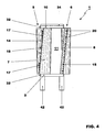
- At least one of the airfoil portions 5, 6 has through holes 20 arranged to let cooling air passing therethrough.
- FIGs 1 and 4 show only the airfoil portion 6 provided with these through holes, it is anyhow clear that in different embodiments both airfoil portions 5 and 6 may be provided with these through holes 20 or only the airfoil portion 5 may have the through holes 20.
- the through holes 20 may also be provided at the platform 2 and/or at the shroud 10.
- FIGS 3 and 5 show a blade 1 connected to other blades 1, assembled onto a blade carrier 22.
- the airfoil portion 6 with operating surface 8 defining a pressure side of a blade 1 is connected to an airfoil portion 5 with operating surface 7 defining a suction side of a different, adjacent blade 1; the two airfoils portions 5 and 6 of the two different adjacent blades 1 connected each other together define an airfoil 24.
- Figure 3 shows that between the connected airfoil portions 5 and 6 (i.e. inside of each airfoil 24 defined by them), a chamber 25 is defined.
- the lower part of the chamber 25 is closed by the platforms 2 of two adjacent blades 1 and its upper part is closed by the shrouds 10 of two adjacent blades 1.
- the platform 2 has preferably straight side borders to make it easier housing a seal ( figure 2 ).
- the platform 2 has its side borders shaped with a curved profile.
- shroud 10 has straight side borders to make it easier housing a seal.
- shroud 10 may have side borders shaped with a curved profile.
- side borders of the platform and shroud may comprise every combination of the above cited types (for example platform with straight side borders and shroud with a curved profile or vice versa).
- the chamber 25 may be empty or house the heat transfer enhancers (for example ribs and/or pins and/or fins 17) and/or the spacers 18.
- the heat transfer enhancers for example ribs and/or pins and/or fins 17
- the chamber 25 may also house a tubular insert 27 arranged to feed compressed cooling air inside of the chamber 25.
- tubular insert 27 passes through a hole 26 of the platform 2 and has an end inside of the chamber 25 and an opposite end outside of the chamber 25, in the region 28 of the roots 3 of the blades.
- the tubular insert 27 may have different shapes such as for example circular or oval shape, nevertheless it has preferably a shape similar to the inner profile of the inside surfaces 14 and 15.
- tubular insert 27 may be separated from the airfoil portions 5 and 6 and may be provided with spacers 30 arranged to rest against the inner surfaces 14 and 15 of the airfoil portions 5 and 6.
- tubular insert 27 may not be provided with the spacers 30; the spacers 30 could extend from the inner surfaces 14 and 15 of the airfoil portions 5 and 6; in this embodiment the spacer 30 may have the same structure shown in figure 10 for the spacer 18.
- the tubular insert 27 has a number of calibrated through holes 31, arranged to let the cooling air pass through, to control the cooling air passing therethrough and thus entering the chamber 25.
- seals similar to traditional seals such as straight bar shaped plates 33 may be provided; these seals are inserted in facing slots 32 indented in the side borders of the platform 2 and shroud 10.
- the plate 33 is substantially C-shaped and is inserted in facing slots 32 indented in the curved side borders of adjacent platform 2 and shrouds 10.
- the blades 1 also comprise seals 34 at the shrouds 10 for preventing the hot gases from passing through the gap between the shrouds 10 and a casing 35 of the gas turbine.
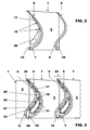
- the airfoil portions 5 and 6 define gaps 38, 39 between their facing edges at the leading edges and trailing edges; through these gaps 38, 39 compressed air fed via the tubular insert 27 into the chamber 25 may be injected.
- Figure 7 shows a first possible configuration for the gap 38 between the airfoil portions 5 and 6.
- the gap 38 defines a slit.
- Figure 8 shows a second possible configuration for the gap 38 between the airfoil portions 5 and 6.
- the edges that define the gap 38 have a step 40 to define a kind of labyrinth seal.
- Figure 9 shows a third possible configuration for the gap 38 between the airfoil portions 5 and 6.
- the airfoil portion 5 has a spring 41, provided with through holes 41a to let the air pass through; the spring 41 rests against the airfoil portion 6.
- the airfoil portion 5 may have a plurality of springs with slits between them; in addition the springs 41 may also be connected to the airfoil portion 6 and have its end resting against the airfoil portion 5 or, when a plurality of springs 41 are provided, some of them may be connected to the airfoil portion 5 and other to the airfoil portion 6.
- the gap 39 may have the same configuration as the gap 38 or also a different configuration similar to those already described with reference to the gap 38.
- the hot gases generated in a combustion chamber by burning a mixture of compressed air coming from a compressor and fuel, are expanded in the turbine.
- the hot gases pass through the channels 11 defined between the platform 2, the airfoil portions 5 and 6 and the shroud 10, delivering mechanical power to the rotor.
- heat transfer enhancers 17 for example ribs and/or pins and/or fins
- spacers 18 and 30 can be manufactured in an easy, cheap and fast way, and can for example be realised in one piece with the airfoil portions or may be manufactured separately and then connected thereto for example by brazing or welding.
- the heat transfer enhancers 17 can be optimised in relation to the desired cooling effect instead of the manufacturing constrains; this lets the cooling problems to be sensibly reduced in comparison to similar traditional blades.
- the shroud lets the vibration problems of the airfoils be reduced.
- Figures 4 and 4a shows a different embodiment with the root 3 defined by three carrying ribs 42 and figure 4c shows a further embodiments with the root 3 defined by carrying ribs 42.
- FIG. 6 shows an embodiment of a blade 1 similar to the blade already described, in this respect the same references are used in figure 6 to define the same or similar elements.
- the blade of figure 6 has substantially the same features as the blade of figure 1 , but it is not provided with the shroud 10.
- the turbine blade being a rotor blade and/or a guide vane (i.e. a stator blade) conceived in this manner is susceptible to numerous modifications and variants, all falling within the scope of the inventive concept; moreover all details can be replaced by technically equivalent elements.
Landscapes
- Engineering & Computer Science (AREA)
- Mechanical Engineering (AREA)
- General Engineering & Computer Science (AREA)
- Physics & Mathematics (AREA)
- Fluid Mechanics (AREA)
- Architecture (AREA)
- Turbine Rotor Nozzle Sealing (AREA)
Claims (15)
- Aube (1) comprenant une plate-forme (2) et au moins une emplanture (3) prévue pour être raccordée à un support d'aubes (22), caractérisée en ce que depuis les côtés circonférentiels opposés de la plate-forme (2) s'étendent des portions de surface portante (5, 6), chacune définissant une surface fonctionnelle (7, 8) étant la surface en regard de l'autre portion de surface portante (6, 5), une surface fonctionnelle (7, 8) de l'une des portions de surface portante (5, 6) définissant un côté d'aspiration et l'autre surface fonctionnelle de l'autre portion de surface portante définissant un côté pression, et, une fois assemblées, les deux portions de surface portante (5) et (6) de deux aubes (1) adjacentes différentes connectées l'une à l'autre définissent ensemble une surface portante (24).
- Aube (1) selon la revendication 1, caractérisée en ce qu'elle comprend une virole (10) connectée aux extrémités des portions de surface portante (5, 6), la plate-forme (2) avec les portions de surface portante (5, 6) et la virole (10) définissant un canal fermé (11).
- Aube (1) selon l'une quelconque ou plusieurs des revendications précédentes, caractérisée en ce qu'une surface de chaque portion de surface portante (5, 6) en regard de la surface fonctionnelle (7, 8) définit une surface interne (14, 15) d'une surface portante (24) qui, lorsqu'un certain nombre d'aubes (1) sont assemblées sur un support d'aubes (22), est définie par deux portions de surface portante (5, 6) adjacentes.
- Aube (1) selon l'une quelconque ou plusieurs des revendications précédentes, caractérisée en ce que la surface interne (14, 15) d'au moins l'une des portions de surface portante (5, 6) présente des éléments amplificateurs du transfert thermique (17) agencés de manière à amplifier les échanges thermiques.
- Aube (1) selon l'une quelconque ou plusieurs des revendications précédentes, caractérisée en ce que la surface interne (14, 15) d'au moins l'une des portions de surface portante (5, 6) comprend des éléments d'espacement (18, 30), de telle sorte que lorsqu'un certain nombre d'aubes (1) est assemblé sur un support d'aubes (22), les éléments d'espacement (18, 30) soient interposés entre deux portions de surface portante adjacentes (5, 6).
- Aube (1) selon l'une quelconque ou plusieurs des revendications précédentes, caractérisée en ce qu'au moins l'une des portions de surface portante (5, 6) et/ou la plate-forme (2) et/ou la virole (10) présentent des trous traversants (20) agencés de manière à laisser l'air de refroidissement passer à travers.
- Aube (1) selon l'une quelconque ou plusieurs des revendications précédentes, caractérisée en ce qu'elle est assemblée sur un support d'aubes (22) en position adjacente à d'autres aubes (1), une portion de surface portante (6) avec une surface fonctionnelle définissant un côté pression d'une aube (1) étant connectée à une portion de surface portante (5) avec une surface fonctionnelle définissant un côté aspiration d'une aube adjacente (1).
- Aube (1) selon l'une quelconque ou plusieurs des revendications précédentes, caractérisée en ce qu'entre les portions de surface portante adjacente (5, 6) est définie une chambre (25).
- Aube (1) selon l'une quelconque ou plusieurs des revendications précédentes, caractérisée en ce qu'elle comprend un insert tubulaire (27) ayant une extrémité à l'intérieur de la chambre (25) et une extrémité opposée à l'extérieur de la chambre (25) dans la région (28) des emplantures (3) des aubes (1).
- Aube (1) selon l'une quelconque ou plusieurs des revendications précédentes, caractérisée en ce que l'insert tubulaire (27) a un certain nombre de trous traversants calibrés (31) agencés de manière à réguler l'air de refroidissement entrant dans la chambre (25).
- Aube (1) selon l'une quelconque ou plusieurs des revendications précédentes, caractérisée en ce que la plate-forme (2) a un trou (26) pour laisser passer l'insert tubulaire.
- Aube (1) selon l'une quelconque ou plusieurs des revendications précédentes, caractérisée en ce qu'elle comprend des joints d'étanchéité (32, 33) prévus au niveau des bordures latérales de la plate-forme (2) et/ou au niveau des bordures latérale de la virole (10).
- Aube (1) selon l'une quelconque ou plusieurs des revendications précédentes, caractérisée en ce qu'elle comprend des joints d'étanchéité (34) au niveau des viroles (10).
- Aube (1) selon l'une quelconque ou plusieurs des revendications précédentes, caractérisée en ce qu'il s'agit d'une aube de rotor ou d'une ailette de guidage.
- Agencement d'aubes (1) comprenant des aubes selon l'une quelconque ou plusieurs des revendications précédentes, caractérisé en ce que les aubes (1) sont agencées et connectées à un support d'aubes (22) de telle sorte qu'une surface fonctionnelle (7, 8) de l'une des portions de surface portante (5, 6) d'une aube (1) définisse un côté aspiration et que l'autre surface fonctionnelle de l'autre portion de surface portante de la même aube (1) définisse un côté pression des surfaces portantes défini par des portions de surface portante (5,6) adjacentes d'aubes adjacentes.
Priority Applications (4)
| Application Number | Priority Date | Filing Date | Title |
|---|---|---|---|
| EP20090177829 EP2333240B1 (fr) | 2009-12-03 | 2009-12-03 | Aube de turbine en deux parties avec des caractéristiques de refroidissement et de vibrations améliorées |
| US12/958,727 US9017035B2 (en) | 2009-12-03 | 2010-12-02 | Turbine blade |
| JP2010268897A JP5777330B2 (ja) | 2009-12-03 | 2010-12-02 | タービンブレード |
| CN201010585344.5A CN102102542B (zh) | 2009-12-03 | 2010-12-03 | 涡轮叶片 |
Applications Claiming Priority (1)
| Application Number | Priority Date | Filing Date | Title |
|---|---|---|---|
| EP20090177829 EP2333240B1 (fr) | 2009-12-03 | 2009-12-03 | Aube de turbine en deux parties avec des caractéristiques de refroidissement et de vibrations améliorées |
Publications (2)
| Publication Number | Publication Date |
|---|---|
| EP2333240A1 EP2333240A1 (fr) | 2011-06-15 |
| EP2333240B1 true EP2333240B1 (fr) | 2013-02-13 |
Family
ID=42126048
Family Applications (1)
| Application Number | Title | Priority Date | Filing Date |
|---|---|---|---|
| EP20090177829 Not-in-force EP2333240B1 (fr) | 2009-12-03 | 2009-12-03 | Aube de turbine en deux parties avec des caractéristiques de refroidissement et de vibrations améliorées |
Country Status (4)
| Country | Link |
|---|---|
| US (1) | US9017035B2 (fr) |
| EP (1) | EP2333240B1 (fr) |
| JP (1) | JP5777330B2 (fr) |
| CN (1) | CN102102542B (fr) |
Families Citing this family (14)
| Publication number | Priority date | Publication date | Assignee | Title |
|---|---|---|---|---|
| FR2984786B1 (fr) * | 2011-12-23 | 2014-01-03 | Snecma | Procede de fabrication d'une aube creuse |
| JP2013213427A (ja) * | 2012-04-02 | 2013-10-17 | Toshiba Corp | 中空ノズルおよびその製造方法 |
| CN104541024B (zh) | 2012-08-20 | 2018-09-28 | 安萨尔多能源英国知识产权有限公司 | 用于旋转机器的内部冷却式翼型件 |
| CN103742203B (zh) * | 2014-02-11 | 2016-04-27 | 上海电气电站设备有限公司 | 汽轮机末级长叶片 |
| US20160281517A1 (en) * | 2015-03-26 | 2016-09-29 | Solar Turbines Incorporated | Cast nozzle with split airfoil |
| US20210381383A1 (en) * | 2016-08-30 | 2021-12-09 | Siemens Aktiengesellschaft | Flow directing structure for a turbine stator stage |
| WO2018044270A1 (fr) * | 2016-08-30 | 2018-03-08 | Siemens Aktiengesellschaft | Segment pour étage de rotor de turbine |
| US10662782B2 (en) * | 2016-11-17 | 2020-05-26 | Raytheon Technologies Corporation | Airfoil with airfoil piece having axial seal |
| CN106593544A (zh) * | 2017-01-23 | 2017-04-26 | 中国航发沈阳发动机研究所 | 一种涡轮转子叶片的尾缘冷却结构及具有其的发动机 |
| GB201720829D0 (en) | 2017-12-14 | 2018-01-31 | Rolls Royce Plc | Aerofoil and method of manufacture |
| GB201720828D0 (en) | 2017-12-14 | 2018-01-31 | Rolls Royce Plc | Aerofoil |
| FR3108667B1 (fr) * | 2020-03-27 | 2022-08-12 | Safran Ceram | Aube de stator de turbine en matériau composite à matrice céramique |
| US11898463B2 (en) * | 2021-03-29 | 2024-02-13 | Rtx Corporation | Airfoil assembly with fiber-reinforced composite rings |
| US11549378B1 (en) | 2022-06-03 | 2023-01-10 | Raytheon Technologies Corporation | Airfoil assembly with composite rings and sealing shelf |
Family Cites Families (17)
| Publication number | Priority date | Publication date | Assignee | Title |
|---|---|---|---|---|
| US2930580A (en) * | 1953-03-12 | 1960-03-29 | Gen Motors Corp | Two-piece turbine bucket |
| GB2028928B (en) | 1978-08-17 | 1982-08-25 | Ross Royce Ltd | Aerofoil blade for a gas turbine engine |
| JPH0510102A (ja) | 1991-07-02 | 1993-01-19 | Hitachi Ltd | ガスタービン翼及びガスタービン装置 |
| US5203873A (en) | 1991-08-29 | 1993-04-20 | General Electric Company | Turbine blade impingement baffle |
| CN1162345A (zh) | 1994-10-31 | 1997-10-15 | 西屋电气公司 | 带受冷却平台的燃气涡轮叶片 |
| EP0789806B1 (fr) | 1994-10-31 | 1998-07-29 | Westinghouse Electric Corporation | Pale de turbine a gaz avec plateforme refroidie |
| EP0930419A4 (fr) * | 1997-06-06 | 2001-03-07 | Mitsubishi Heavy Ind Ltd | Aube de turbine a gas |
| AU1900799A (en) * | 1997-10-27 | 1999-05-17 | Siemens Westinghouse Power Corporation | Method of bonding cast superalloys |
| WO2000053895A1 (fr) * | 1999-03-11 | 2000-09-14 | Alm Development, Inc. | Disque rotor de turbine |
| EP1191189A1 (fr) * | 2000-09-26 | 2002-03-27 | Siemens Aktiengesellschaft | Aube de turbine à gaz |
| US6382908B1 (en) * | 2001-01-18 | 2002-05-07 | General Electric Company | Nozzle fillet backside cooling |
| JP2003214107A (ja) | 2002-01-25 | 2003-07-30 | Mitsubishi Heavy Ind Ltd | 軸流タービン翼およびこれを使用したガスタービン、並びに軸流圧縮機 |
| US6742991B2 (en) | 2002-07-11 | 2004-06-01 | Mitsubishi Heavy Industries, Ltd. | Turbine blade and gas turbine |
| US7094031B2 (en) * | 2004-09-09 | 2006-08-22 | General Electric Company | Offset Coriolis turbulator blade |
| JP2006242050A (ja) | 2005-03-02 | 2006-09-14 | Mitsubishi Heavy Ind Ltd | ガスタービンの翼冷却構造 |
| US7371049B2 (en) * | 2005-08-31 | 2008-05-13 | United Technologies Corporation | Manufacturable and inspectable microcircuit cooling for blades |
| US7322796B2 (en) | 2005-08-31 | 2008-01-29 | United Technologies Corporation | Turbine vane construction |
-
2009
- 2009-12-03 EP EP20090177829 patent/EP2333240B1/fr not_active Not-in-force
-
2010
- 2010-12-02 JP JP2010268897A patent/JP5777330B2/ja not_active Expired - Fee Related
- 2010-12-02 US US12/958,727 patent/US9017035B2/en not_active Expired - Fee Related
- 2010-12-03 CN CN201010585344.5A patent/CN102102542B/zh not_active Expired - Fee Related
Also Published As
| Publication number | Publication date |
|---|---|
| JP5777330B2 (ja) | 2015-09-09 |
| CN102102542A (zh) | 2011-06-22 |
| EP2333240A1 (fr) | 2011-06-15 |
| US20110135497A1 (en) | 2011-06-09 |
| CN102102542B (zh) | 2016-02-10 |
| JP2011122588A (ja) | 2011-06-23 |
| US9017035B2 (en) | 2015-04-28 |
Similar Documents
| Publication | Publication Date | Title |
|---|---|---|
| EP2333240B1 (fr) | Aube de turbine en deux parties avec des caractéristiques de refroidissement et de vibrations améliorées | |
| EP2248996B1 (fr) | Turbine à gaz | |
| EP3064713B1 (fr) | Aube rotorique de turbine et section de turbine associée | |
| CN101852098B (zh) | 具有隔热体的涡轮叶片组件 | |
| EP3155233B1 (fr) | Moteur à turbine à gaz avec système de refroidissement à centrage de rotor dans un diffuseur d'échappement | |
| EP2204545B1 (fr) | Buse comprenant des ouvertures afin de réduire les tensions et moteur à turbine à gaz | |
| US20080101923A1 (en) | Turbomachine turbine ring sector | |
| JP2013245674A (ja) | タービンロータブレード先端における冷却構造 | |
| EP2264283A2 (fr) | Composant refroidi pour moteur à turbine à gaz | |
| JP2017020493A (ja) | タービンバンドのアンチコーディングフランジ | |
| AU2011250785B2 (en) | Gas turbine of the axial flow type | |
| CN110735671A (zh) | 包括多个冷却通道的涡轮机护罩 | |
| US9657579B2 (en) | Cooled vane of a high-pressure turbine | |
| CN106150561B (zh) | 涡轮翼型件扰流器布置 | |
| EP2458152B1 (fr) | Turbine à gaz de type à flux axial | |
| JP5738159B2 (ja) | 軸流タイプのガスタービン | |
| KR20060046516A (ko) | 성곽 형상을 가지는 단부를 구비한 에어포일 삽입체 | |
| JP5507340B2 (ja) | ターボ機械圧縮機ホイール部材 | |
| US9528380B2 (en) | Turbine bucket and method for cooling a turbine bucket of a gas turbine engine | |
| EP2530244B1 (fr) | Stator entourant un rotor et procédé de refroidissement | |
| EP2713009B1 (fr) | Procédé et système de refroidissement pour refroidir des aubes d'au moins une rangée d'aubes dans une turbomachine rotative | |
| US10738638B2 (en) | Rotor blade with wheel space swirlers and method for forming a rotor blade with wheel space swirlers | |
| CN105715307B (zh) | 转子和至少一个叶片的布置 | |
| WO2013148403A1 (fr) | Buse de turbine |
Legal Events
| Date | Code | Title | Description |
|---|---|---|---|
| PUAI | Public reference made under article 153(3) epc to a published international application that has entered the european phase |
Free format text: ORIGINAL CODE: 0009012 |
|
| AK | Designated contracting states |
Kind code of ref document: A1 Designated state(s): AT BE BG CH CY CZ DE DK EE ES FI FR GB GR HR HU IE IS IT LI LT LU LV MC MK MT NL NO PL PT RO SE SI SK SM TR |
|
| AX | Request for extension of the european patent |
Extension state: AL BA RS |
|
| 17P | Request for examination filed |
Effective date: 20111212 |
|
| 17Q | First examination report despatched |
Effective date: 20120202 |
|
| GRAP | Despatch of communication of intention to grant a patent |
Free format text: ORIGINAL CODE: EPIDOSNIGR1 |
|
| GRAS | Grant fee paid |
Free format text: ORIGINAL CODE: EPIDOSNIGR3 |
|
| GRAA | (expected) grant |
Free format text: ORIGINAL CODE: 0009210 |
|
| AK | Designated contracting states |
Kind code of ref document: B1 Designated state(s): AT BE BG CH CY CZ DE DK EE ES FI FR GB GR HR HU IE IS IT LI LT LU LV MC MK MT NL NO PL PT RO SE SI SK SM TR |
|
| REG | Reference to a national code |
Ref country code: GB Ref legal event code: FG4D |
|
| REG | Reference to a national code |
Ref country code: AT Ref legal event code: REF Ref document number: 596619 Country of ref document: AT Kind code of ref document: T Effective date: 20130215 |
|
| REG | Reference to a national code |
Ref country code: IE Ref legal event code: FG4D |
|
| REG | Reference to a national code |
Ref country code: DE Ref legal event code: R096 Ref document number: 602009013218 Country of ref document: DE Effective date: 20130411 |
|
| REG | Reference to a national code |
Ref country code: AT Ref legal event code: MK05 Ref document number: 596619 Country of ref document: AT Kind code of ref document: T Effective date: 20130213 |
|
| REG | Reference to a national code |
Ref country code: NL Ref legal event code: VDEP Effective date: 20130213 |
|
| REG | Reference to a national code |
Ref country code: LT Ref legal event code: MG4D |
|
| PG25 | Lapsed in a contracting state [announced via postgrant information from national office to epo] |
Ref country code: ES Free format text: LAPSE BECAUSE OF FAILURE TO SUBMIT A TRANSLATION OF THE DESCRIPTION OR TO PAY THE FEE WITHIN THE PRESCRIBED TIME-LIMIT Effective date: 20130524 Ref country code: LT Free format text: LAPSE BECAUSE OF FAILURE TO SUBMIT A TRANSLATION OF THE DESCRIPTION OR TO PAY THE FEE WITHIN THE PRESCRIBED TIME-LIMIT Effective date: 20130213 Ref country code: IS Free format text: LAPSE BECAUSE OF FAILURE TO SUBMIT A TRANSLATION OF THE DESCRIPTION OR TO PAY THE FEE WITHIN THE PRESCRIBED TIME-LIMIT Effective date: 20130613 Ref country code: NO Free format text: LAPSE BECAUSE OF FAILURE TO SUBMIT A TRANSLATION OF THE DESCRIPTION OR TO PAY THE FEE WITHIN THE PRESCRIBED TIME-LIMIT Effective date: 20130513 Ref country code: AT Free format text: LAPSE BECAUSE OF FAILURE TO SUBMIT A TRANSLATION OF THE DESCRIPTION OR TO PAY THE FEE WITHIN THE PRESCRIBED TIME-LIMIT Effective date: 20130213 Ref country code: SE Free format text: LAPSE BECAUSE OF FAILURE TO SUBMIT A TRANSLATION OF THE DESCRIPTION OR TO PAY THE FEE WITHIN THE PRESCRIBED TIME-LIMIT Effective date: 20130213 Ref country code: BG Free format text: LAPSE BECAUSE OF FAILURE TO SUBMIT A TRANSLATION OF THE DESCRIPTION OR TO PAY THE FEE WITHIN THE PRESCRIBED TIME-LIMIT Effective date: 20130513 |
|
| PG25 | Lapsed in a contracting state [announced via postgrant information from national office to epo] |
Ref country code: GR Free format text: LAPSE BECAUSE OF FAILURE TO SUBMIT A TRANSLATION OF THE DESCRIPTION OR TO PAY THE FEE WITHIN THE PRESCRIBED TIME-LIMIT Effective date: 20130514 Ref country code: BE Free format text: LAPSE BECAUSE OF FAILURE TO SUBMIT A TRANSLATION OF THE DESCRIPTION OR TO PAY THE FEE WITHIN THE PRESCRIBED TIME-LIMIT Effective date: 20130213 Ref country code: FI Free format text: LAPSE BECAUSE OF FAILURE TO SUBMIT A TRANSLATION OF THE DESCRIPTION OR TO PAY THE FEE WITHIN THE PRESCRIBED TIME-LIMIT Effective date: 20130213 Ref country code: SI Free format text: LAPSE BECAUSE OF FAILURE TO SUBMIT A TRANSLATION OF THE DESCRIPTION OR TO PAY THE FEE WITHIN THE PRESCRIBED TIME-LIMIT Effective date: 20130213 Ref country code: PL Free format text: LAPSE BECAUSE OF FAILURE TO SUBMIT A TRANSLATION OF THE DESCRIPTION OR TO PAY THE FEE WITHIN THE PRESCRIBED TIME-LIMIT Effective date: 20130213 Ref country code: PT Free format text: LAPSE BECAUSE OF FAILURE TO SUBMIT A TRANSLATION OF THE DESCRIPTION OR TO PAY THE FEE WITHIN THE PRESCRIBED TIME-LIMIT Effective date: 20130613 Ref country code: LV Free format text: LAPSE BECAUSE OF FAILURE TO SUBMIT A TRANSLATION OF THE DESCRIPTION OR TO PAY THE FEE WITHIN THE PRESCRIBED TIME-LIMIT Effective date: 20130213 |
|
| PG25 | Lapsed in a contracting state [announced via postgrant information from national office to epo] |
Ref country code: HR Free format text: LAPSE BECAUSE OF FAILURE TO SUBMIT A TRANSLATION OF THE DESCRIPTION OR TO PAY THE FEE WITHIN THE PRESCRIBED TIME-LIMIT Effective date: 20130213 |
|
| PG25 | Lapsed in a contracting state [announced via postgrant information from national office to epo] |
Ref country code: EE Free format text: LAPSE BECAUSE OF FAILURE TO SUBMIT A TRANSLATION OF THE DESCRIPTION OR TO PAY THE FEE WITHIN THE PRESCRIBED TIME-LIMIT Effective date: 20130213 Ref country code: CZ Free format text: LAPSE BECAUSE OF FAILURE TO SUBMIT A TRANSLATION OF THE DESCRIPTION OR TO PAY THE FEE WITHIN THE PRESCRIBED TIME-LIMIT Effective date: 20130213 Ref country code: RO Free format text: LAPSE BECAUSE OF FAILURE TO SUBMIT A TRANSLATION OF THE DESCRIPTION OR TO PAY THE FEE WITHIN THE PRESCRIBED TIME-LIMIT Effective date: 20130213 Ref country code: DK Free format text: LAPSE BECAUSE OF FAILURE TO SUBMIT A TRANSLATION OF THE DESCRIPTION OR TO PAY THE FEE WITHIN THE PRESCRIBED TIME-LIMIT Effective date: 20130213 Ref country code: SK Free format text: LAPSE BECAUSE OF FAILURE TO SUBMIT A TRANSLATION OF THE DESCRIPTION OR TO PAY THE FEE WITHIN THE PRESCRIBED TIME-LIMIT Effective date: 20130213 Ref country code: NL Free format text: LAPSE BECAUSE OF FAILURE TO SUBMIT A TRANSLATION OF THE DESCRIPTION OR TO PAY THE FEE WITHIN THE PRESCRIBED TIME-LIMIT Effective date: 20130213 |
|
| PLBE | No opposition filed within time limit |
Free format text: ORIGINAL CODE: 0009261 |
|
| STAA | Information on the status of an ep patent application or granted ep patent |
Free format text: STATUS: NO OPPOSITION FILED WITHIN TIME LIMIT |
|
| PG25 | Lapsed in a contracting state [announced via postgrant information from national office to epo] |
Ref country code: IT Free format text: LAPSE BECAUSE OF FAILURE TO SUBMIT A TRANSLATION OF THE DESCRIPTION OR TO PAY THE FEE WITHIN THE PRESCRIBED TIME-LIMIT Effective date: 20130213 |
|
| 26N | No opposition filed |
Effective date: 20131114 |
|
| REG | Reference to a national code |
Ref country code: DE Ref legal event code: R097 Ref document number: 602009013218 Country of ref document: DE Effective date: 20131114 |
|
| REG | Reference to a national code |
Ref country code: CH Ref legal event code: PL |
|
| PG25 | Lapsed in a contracting state [announced via postgrant information from national office to epo] |
Ref country code: MC Free format text: LAPSE BECAUSE OF FAILURE TO SUBMIT A TRANSLATION OF THE DESCRIPTION OR TO PAY THE FEE WITHIN THE PRESCRIBED TIME-LIMIT Effective date: 20130213 Ref country code: LU Free format text: LAPSE BECAUSE OF FAILURE TO SUBMIT A TRANSLATION OF THE DESCRIPTION OR TO PAY THE FEE WITHIN THE PRESCRIBED TIME-LIMIT Effective date: 20131203 |
|
| REG | Reference to a national code |
Ref country code: IE Ref legal event code: MM4A |
|
| PG25 | Lapsed in a contracting state [announced via postgrant information from national office to epo] |
Ref country code: CH Free format text: LAPSE BECAUSE OF NON-PAYMENT OF DUE FEES Effective date: 20131231 Ref country code: IE Free format text: LAPSE BECAUSE OF NON-PAYMENT OF DUE FEES Effective date: 20131203 Ref country code: LI Free format text: LAPSE BECAUSE OF NON-PAYMENT OF DUE FEES Effective date: 20131231 |
|
| PG25 | Lapsed in a contracting state [announced via postgrant information from national office to epo] |
Ref country code: SM Free format text: LAPSE BECAUSE OF FAILURE TO SUBMIT A TRANSLATION OF THE DESCRIPTION OR TO PAY THE FEE WITHIN THE PRESCRIBED TIME-LIMIT Effective date: 20130213 |
|
| PG25 | Lapsed in a contracting state [announced via postgrant information from national office to epo] |
Ref country code: CY Free format text: LAPSE BECAUSE OF FAILURE TO SUBMIT A TRANSLATION OF THE DESCRIPTION OR TO PAY THE FEE WITHIN THE PRESCRIBED TIME-LIMIT Effective date: 20130213 Ref country code: TR Free format text: LAPSE BECAUSE OF FAILURE TO SUBMIT A TRANSLATION OF THE DESCRIPTION OR TO PAY THE FEE WITHIN THE PRESCRIBED TIME-LIMIT Effective date: 20130213 |
|
| PG25 | Lapsed in a contracting state [announced via postgrant information from national office to epo] |
Ref country code: MK Free format text: LAPSE BECAUSE OF FAILURE TO SUBMIT A TRANSLATION OF THE DESCRIPTION OR TO PAY THE FEE WITHIN THE PRESCRIBED TIME-LIMIT Effective date: 20130213 Ref country code: HU Free format text: LAPSE BECAUSE OF FAILURE TO SUBMIT A TRANSLATION OF THE DESCRIPTION OR TO PAY THE FEE WITHIN THE PRESCRIBED TIME-LIMIT; INVALID AB INITIO Effective date: 20091203 |
|
| PG25 | Lapsed in a contracting state [announced via postgrant information from national office to epo] |
Ref country code: MT Free format text: LAPSE BECAUSE OF FAILURE TO SUBMIT A TRANSLATION OF THE DESCRIPTION OR TO PAY THE FEE WITHIN THE PRESCRIBED TIME-LIMIT Effective date: 20130213 |
|
| REG | Reference to a national code |
Ref country code: FR Ref legal event code: PLFP Year of fee payment: 7 |
|
| REG | Reference to a national code |
Ref country code: DE Ref legal event code: R081 Ref document number: 602009013218 Country of ref document: DE Owner name: GENERAL ELECTRIC TECHNOLOGY GMBH, CH Free format text: FORMER OWNER: ALSTOM TECHNOLOGY LTD., BADEN, CH Ref country code: DE Ref legal event code: R081 Ref document number: 602009013218 Country of ref document: DE Owner name: ANSALDO ENERGIA IP UK LIMITED, GB Free format text: FORMER OWNER: ALSTOM TECHNOLOGY LTD., BADEN, CH |
|
| REG | Reference to a national code |
Ref country code: FR Ref legal event code: CD Owner name: ALSTOM TECHNOLOGY LTD, CH Effective date: 20161110 |
|
| REG | Reference to a national code |
Ref country code: FR Ref legal event code: PLFP Year of fee payment: 8 |
|
| PGFP | Annual fee paid to national office [announced via postgrant information from national office to epo] |
Ref country code: GB Payment date: 20161222 Year of fee payment: 8 |
|
| REG | Reference to a national code |
Ref country code: DE Ref legal event code: R081 Ref document number: 602009013218 Country of ref document: DE Owner name: ANSALDO ENERGIA IP UK LIMITED, GB Free format text: FORMER OWNER: GENERAL ELECTRIC TECHNOLOGY GMBH, BADEN, CH |
|
| REG | Reference to a national code |
Ref country code: GB Ref legal event code: 732E Free format text: REGISTERED BETWEEN 20170824 AND 20170830 |
|
| REG | Reference to a national code |
Ref country code: FR Ref legal event code: PLFP Year of fee payment: 9 |
|
| REG | Reference to a national code |
Ref country code: FR Ref legal event code: TP Owner name: ANSALDO ENERGIA IP UK LIMITED, GB Effective date: 20171221 |
|
| PGFP | Annual fee paid to national office [announced via postgrant information from national office to epo] |
Ref country code: FR Payment date: 20171221 Year of fee payment: 9 Ref country code: DE Payment date: 20171211 Year of fee payment: 9 |
|
| GBPC | Gb: european patent ceased through non-payment of renewal fee |
Effective date: 20171203 |
|
| PG25 | Lapsed in a contracting state [announced via postgrant information from national office to epo] |
Ref country code: GB Free format text: LAPSE BECAUSE OF NON-PAYMENT OF DUE FEES Effective date: 20171203 |
|
| REG | Reference to a national code |
Ref country code: DE Ref legal event code: R119 Ref document number: 602009013218 Country of ref document: DE |
|
| PG25 | Lapsed in a contracting state [announced via postgrant information from national office to epo] |
Ref country code: DE Free format text: LAPSE BECAUSE OF NON-PAYMENT OF DUE FEES Effective date: 20190702 Ref country code: FR Free format text: LAPSE BECAUSE OF NON-PAYMENT OF DUE FEES Effective date: 20181231 |