EP2333208B2 - Motor vehicle lock - Google Patents
Motor vehicle lock Download PDFInfo
- Publication number
- EP2333208B2 EP2333208B2 EP10015469.9A EP10015469A EP2333208B2 EP 2333208 B2 EP2333208 B2 EP 2333208B2 EP 10015469 A EP10015469 A EP 10015469A EP 2333208 B2 EP2333208 B2 EP 2333208B2
- Authority
- EP
- European Patent Office
- Prior art keywords
- rotary
- pawl
- catch
- switch
- switching
- Prior art date
- Legal status (The legal status is an assumption and is not a legal conclusion. Google has not performed a legal analysis and makes no representation as to the accuracy of the status listed.)
- Active
Links
- 230000007246 mechanism Effects 0.000 claims description 6
- 230000008859 change Effects 0.000 claims description 2
- 230000000694 effects Effects 0.000 claims description 2
- 230000001419 dependent effect Effects 0.000 claims 4
- 238000000034 method Methods 0.000 description 29
- 230000008569 process Effects 0.000 description 29
- 230000007704 transition Effects 0.000 description 5
- 238000012544 monitoring process Methods 0.000 description 4
- 230000015572 biosynthetic process Effects 0.000 description 3
- 238000001514 detection method Methods 0.000 description 3
- 238000010586 diagram Methods 0.000 description 3
- 238000005516 engineering process Methods 0.000 description 2
- 230000009467 reduction Effects 0.000 description 2
- 230000001960 triggered effect Effects 0.000 description 2
- 230000001364 causal effect Effects 0.000 description 1
- 238000005352 clarification Methods 0.000 description 1
- 230000003993 interaction Effects 0.000 description 1
- 239000002184 metal Substances 0.000 description 1
- 230000003287 optical effect Effects 0.000 description 1
Images


Classifications
-
- E—FIXED CONSTRUCTIONS
- E05—LOCKS; KEYS; WINDOW OR DOOR FITTINGS; SAFES
- E05B—LOCKS; ACCESSORIES THEREFOR; HANDCUFFS
- E05B85/00—Details of vehicle locks not provided for in groups E05B77/00 - E05B83/00
- E05B85/20—Bolts or detents
- E05B85/24—Bolts rotating about an axis
- E05B85/26—Cooperation between bolts and detents
-
- E—FIXED CONSTRUCTIONS
- E05—LOCKS; KEYS; WINDOW OR DOOR FITTINGS; SAFES
- E05B—LOCKS; ACCESSORIES THEREFOR; HANDCUFFS
- E05B81/00—Power-actuated vehicle locks
- E05B81/12—Power-actuated vehicle locks characterised by the function or purpose of the powered actuators
- E05B81/20—Power-actuated vehicle locks characterised by the function or purpose of the powered actuators for assisting final closing or for initiating opening
-
- E—FIXED CONSTRUCTIONS
- E05—LOCKS; KEYS; WINDOW OR DOOR FITTINGS; SAFES
- E05B—LOCKS; ACCESSORIES THEREFOR; HANDCUFFS
- E05B81/00—Power-actuated vehicle locks
- E05B81/54—Electrical circuits
- E05B81/64—Monitoring or sensing, e.g. by using switches or sensors
- E05B81/66—Monitoring or sensing, e.g. by using switches or sensors the bolt position, i.e. the latching status
- E05B81/68—Monitoring or sensing, e.g. by using switches or sensors the bolt position, i.e. the latching status by sensing the position of the detent
-
- E—FIXED CONSTRUCTIONS
- E05—LOCKS; KEYS; WINDOW OR DOOR FITTINGS; SAFES
- E05B—LOCKS; ACCESSORIES THEREFOR; HANDCUFFS
- E05B81/00—Power-actuated vehicle locks
- E05B81/54—Electrical circuits
- E05B81/64—Monitoring or sensing, e.g. by using switches or sensors
- E05B81/66—Monitoring or sensing, e.g. by using switches or sensors the bolt position, i.e. the latching status
Definitions
- the present invention relates to a motor vehicle lock having the features of the preamble of claim 1.
- vehicle lock is to be understood comprehensively. It covers not only side door locks and tailgate locks, but also tailgate locks. Incidentally, the term “vehicle lock” means the entire system, the components of which can also be distributed.
- the well-known motor vehicle lock FR2778939A1 is equipped with a conventional locking mechanism with rotary bolt and pawl.
- the rotary latch can be brought into an open position, into a pre-locking position and into a main locking position, while the pawl can be brought into a closed position and into a lifted position.
- a circuit arrangement is provided, which is assigned a rotary latch switch and a ratchet switch.
- the task of the above circuit arrangement is to monitor the error-free transfer of the rotating bolt into the open position, into the pre-locked position and, above all, into the main locked position. It is important to be able to reliably detect all conceivable error states.
- An error condition that occasionally occurs is that the rotary latch has reached the main detent position, but that the pawl has not, or not fully, engaged. This is also known as mock closure.
- the rotating bolt switch and the pawl switch are each designed as a toggle switch. If the above error state of the false closure is to be detected, at least three signal outputs are to be monitored in the circuit arrangement there. This is complex in terms of control technology.
- the detection of the closed states based on the signal outputs of the two changeover switches is not sufficient in some cases.
- the state in which the rotary bolt is just before the main latching position and the pawl is in the lifted position cannot be distinguished from the state in which the rotary bolt is in the open position and the pawl is in the lifted position.
- the DE 198 61 199 B4 and the DE 10 2007 056 251 A1 each show motor vehicle locks whose locking mechanisms are monitored by means of a three-stage query switch.
- the invention is based on the problem of optimizing the known motor vehicle lock with regard to the detection of locking states and from the point of view of costs.
- both the rotary bolt switch and the pawl switch can in principle be assigned more than three or more than two switching positions. However, it is preferably the case that three switch positions are assigned to the rotary bolt switch and two switch positions to the pawl switch.
- the constellation with a two-stage pawl switch and a three-stage rotary bolt switch allows, with the appropriate wiring, that the three relevant locking states mentioned above and an intermediate state can be displayed via two binary signal outputs.
- the intermediate state which in any case includes the state of the above-mentioned sham closure, is of particular importance. It is preferably the case that the intermediate state also includes the constellation in which the rotating bolt is between the pre-locked position and the main locked position and the pawl is in the lifted-out position. Several such constellations can be assigned to the intermediate state.
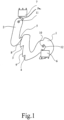
- the proposed motor vehicle lock is equipped with an in 1 equipped with a locking mechanism shown only as an example, which has a rotating bolt 1 and a pawl 2.
- the rotary latch 1 and the pawl 2 are designed here in the usual way as metal stampings. But there are many other variants for the realization of the rotating bolt 1 and the pawl 2 conceivable.
- the pawl 2 can also be designed as a bendable pawl wire that can be brought into locking engagement with the rotating bolt 1 .
- Turnbuckle 1 is in the in 1 shown open position, can be brought into a pre-locked position and in a main locked position.
- the rotating bolt 1 has a corresponding first catch 3 and a main catch 4 .
- the pawl 2 is in a drop-in position, in which it holds the rotating bolt 1 in the main locking position in the pre-locking position, and in the in 1 shown lifting position, in which it releases the rotating bolt 1, can be brought.
- the pawl 2 is equipped with a hook-like formation 5 which can be brought into holding engagement with the first catch 3 and the main catch 4 .
- the locking mechanism is assigned a circuit arrangement for detecting locking states, from which 1 only one rotary bolt switch 6 for detecting the rotary bolt position and one ratchet switch 7 for detecting the ratchet position are shown.
- the two above switches 6, 7 are at in 1 illustrated, preferred variant each configured as a microswitch, which further preferably have a linearly movable plunger as a switching element.
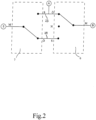
- a schematic circuit diagram of the above circuit arrangement is in 2 shown.
- the circuit diagram shows the fact that the rotating bolt switch 6 can be brought into three switching states, while the pawl switch 7 can be brought into two switching states.
- the three or two switching states are assumed depending on the turning bolt position or the pawl position.
- the proposed solution can be applied particularly advantageously to an arrangement in which the pawl 2 interacts with the rotary bolt 1 as follows:
- the rotary bolt 1 in the open position holds the pawl 2 according to FIG 1 in the withdrawal order.
- the pawl 2 is regularly in contact with a back piece 8 of the rotating bolt 1, as is the case here.
- An adjustment of the rotating bolt 1 from the open position to the pre-locking position causes the pawl 2 to drop into the drop-in position.
- the hook-like formation 5 of the pawl 2 comes into engagement with the first catch 3 of the rotary bolt 1.
- An adjustment of the rotary bolt 1 from the first catch position in the direction of the main catch position again causes the pawl 2 to be lifted into the lifted position.
- the pawl 2 slides along a second back piece 9 of the rotating bolt 1 .
- a further adjustment of the rotating bolt 1 into the main locking position now causes the repeated engagement of the pawl 2 in the engaged position.
- the hook-like formation 5 of the pawl 2 comes into holding engagement with the main catch 4 of the rotating bolt 1.
- the rotary bolt 1 which can be pivoted about a rotary bolt axis 10 , has a contour 12 associated with the rotary bolt switch 6 .
- the contour 12 is in engagement with a movable switching element of the rotary bolt switch 6 and, depending on the position of the rotary bolt 1, ensures that the switching element is deflected accordingly.
- the contour 12 is here and preferably configured in the manner of a web which protrudes from the rotating bolt 1 in the direction of the rotating bolt axis 10 .
- the pawl 2 which is pivotable about a pawl axis 11, is equipped with a contour 7a, which is correspondingly engaged with the pawl switch 7 or can be brought into engagement.
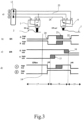
- Figure 3a shows the circuit arrangement for detecting the locking states with the rotary bolt switch 6 and the pawl switch 7, which according to the circuit in 2 is constructed.
- the two switches 6, 7 are connected to a switching strip 13, via which the circuit arrangement can be connected to a higher-level controller.
- the safety edge 13 has an input E to which ground potential is preferably applied.
- the safety edge 13 also has two signal outputs A, B.
- Figure 3a shows the internal switching position within the two switches 6, 7 for the respective closed state.
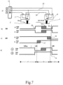
- the Figure 3b ) and c) each show the switching curves of the pawl switch 7 and the rotary bolt switch 6 over the adjustment range of the rotary bolt 1.
- the switching curves of the pawl switch 7 are labeled "SK”
- the switch curves of the rotary bolt switch 6 are labeled "DR”.
- FIG. 3d shows the resulting signal curve at the signal outputs A and B.
- a vertical pointer 14 extends over the drawings 3b), c) and d) to show which position of the rotating bolt 1 the in Figure 3a ) corresponds to the switching state shown.
- the rotary bolt switch 6 has two switching points 15, 16, which are on the one hand near the pre-locked position VR and on the other hand near the main lock position HR. It is preferably the case that the adjustment range of rotary bolt 1 with regard to the switching positions of rotary bolt switch 6 here and preferably immediately next to one another has an open adjustment range 17, an intermediate adjustment range 18 and a main locking adjustment range 19, in which rotary bolt switch 6 correspondingly an open switch position ( 3 , 4 ), an intermediate switching position ( figure 5 , 6 ) and a main position ( 7 , 8th ) occupies.
- the open position and the pre-locked position in the open adjustment range 17 ( 3 , 4 ) are located and that the main locking position is in the main locking adjustment range 19 ( 7 , 8th ) is located.
- the switching points 15, 16 are arranged at a distance from the pre-locking position VR on the one hand and the main locking position HR on the other hand. This allows a switching behavior that is particularly insensitive to tolerances to be implemented. The geometric tolerances that occur in the motor vehicle lock in question are explained further below.
- the representation in Figure 3b The switching points 20, 21, 22 of the pawl 2 can also be seen.
- the lifted position of the pawl 2 corresponds to a lifted switching position and the engaged position of the pawl 2 corresponds to an engaged switching position of the pawl switch 7.
- the switching point 20 corresponds to the engagement of the pawl 2 in the first position 3, while the switching point 21 corresponds to the repeated lifting of the pawl 2 corresponds to the adjustment of the rotating bolt 1 in the direction of the main detent position.
- the switching point 22 goes back to the engagement of the pawl 2 in the main position 4.
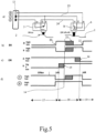
- FIG. 3 A synopsis of Figures 3 to 8 shows that the two switches 6, 7 are interconnected in such a way that the circuit arrangement provides a first binary signal output A and a second binary signal output B, specifically to indicate an open state ( 3 ), in which the rotating bolt 1 is in the open position and the pawl 2 is in the lifted position, a pre-locking state ( 4 ), in which the rotating bolt 1 is in the pre-locked position and the pawl 2 is in the closed position and a main locking state ( 8 ) in which the rotating bolt 1 is in the main locking position and the pawl 2 is in the closed position.
- An intermediate state can also be displayed, which here and preferably includes various constellations ( 6 , 7 ).
- a constellation associated with the intermediate state is that the rotating bolt 1 is in any case in the area of the main locking position, in particular in the main locking position, and the pawl 2 is in the lifted position (apparent locking). this is in 7 shown for the state in which the rotary latch 1 has not yet fully reached the main detent position.
- the intermediate position also includes the constellation in which the Turnbuckle 1 is in the middle area between the pre-locked position and the main locked position and the pawl 2 is in the lifted position ( 6 ).
- a combination of these two states in the intermediate state is appropriate, since both constellations are not the constellations to be primarily recorded.
- the circuit arrangement provides an input E which is connected to an input potential for switching through to the two signal outputs A, B.
- the input potential is the ground potential in the exemplary embodiment that is shown and is preferred in this respect.
- the signal outputs A, B are regularly connected to a pull-up resistor, so that these signal outputs have a high potential if they are not connected to ground potential via the switches 6, 7.
- the above switches are electronic switches in which the switching process is not based on physical contact but essentially on a measuring process.
- the Figures 2 to 8 show, however, an embodiment with electromechanically contacting switches, which are characterized by high robustness and low cost.
- the two switches 6, 7 are designed as changeover switches and each have a central contact M and two switch contacts that can be brought into contact with the central contact M, depending on the switching position.
- the middle contact M is assigned to the movable switching element of the respective changeover switch 6, 7 and is regularly referred to as the "common" contact.
- the rotary bolt switch 6 is designed as a center-zero switch. This means that the rotary bolt switch 6 is not only assigned two switch positions in order to connect the switch contacts ⁇ and S to the center contact M, but also a center-zero switch position, which lies in particular between the two other switch positions and which here and preferably the Intermediate switching position is ( figure 5 , 6 ).
- the center-zero switch position of the rotary latch switch 6 is in the figure 5 , 6 , indicated by the reference character "N".
- the center contact M When the rotary bolt switch 6 is in the center-zero switching position, the center contact M is usually connected neither to the two switching contacts ⁇ , S, nor to any other contact, which, in combination with a pull-up resistor mentioned above, leads to a particularly simple structure . However, it would be conceivable to assign a further contact to the center-zero switching position, which would be in connection with the center contact M in the center-zero switching position and could be connected accordingly.
- the two switching contacts ⁇ , S of the rotary latch switch 6 are each bridged with a different switching contact ⁇ , S of the pawl switch 7, with one of the two bridges 23 providing the first signal output A of the circuit arrangement. This can be shown in the illustration 2 and 3 to 8 remove well.
- the center contact M of the rotary latch switch 6 provides the second signal output B of the circuit arrangement and that the center contact M of the pawl switch 7 provides the input E of the circuit arrangement, to which the input potential is applied.
- center contact M of the pawl switch 7 to provide the second signal output B of the circuit arrangement and for the center contact M of the other switch, in this case the rotary latch switch 6, to provide the input of the circuit arrangement, to which the input potential is applied.
- the transition from 3 on 4 corresponds to the engagement of the pawl 2 in the first position 3, while the rotary bolt switch 6 is in the open switch position.
- the transition from 4 on figure 5 shows the further adjustment of the rotary bolt 1, in which the rotary bolt switch 6 reaches the intermediate switching position without the pawl 2 changing its position.
- the transition from figure 5 on 6 shows the further adjustment of the rotary bolt 1 with the rotary bolt switch 6 remaining in the intermediate switching position, while the pawl 2 is lifted repeatedly.
- the transition from 6 on 7 shows the transfer of the rotary bolt switch 6 from the intermediate switching position to the main locking switching position with an unchanged pawl position.
- the transition from 7 on 8 finally shows the engagement of the pawl 2 in the main position 4 with the rotary bolt switch 6 still in the main position.
- the signal outputs A, B clearly indicate that the open position ( 3 ), the pre-locking position ( 4 ) and the main detent position ( 8 ) show.
- the intermediate state ( 6 , 7 ) is achieved, among other things, when there is an apparent closure, i.e. the turning bolt 1 is in the main locking position and the pawl 2 is in the lifted position. This can easily be shown by starting from the constellation outlined below 8 the pawl 2 from the dropped position is transferred to the withdrawal order. The resulting constellation corresponds exactly to that in 7 shown constellation, i.e. the intermediate state.
- the circuit arrangement according to the proposal is particularly robust against geometric and electrical tolerances, which lead to a shifting of the respective switching points 15, 16, 20, 21, 22.
- the switching points 15, 16, 21 associated geometric tolerances are in the Figures 3 to 8 shown hatched (the geometric tolerances associated with switching points 20 and 22 are negligibly small).
- This representation shows the fact that, in relation to the rotary bolt position, the respective positions of the switching points 15, 16 of the rotary bolt switch 6, here between the open switching position and the intermediate switching position and between the intermediate switching position and the main locking switching position, have geometric tolerances are subject to corresponding tolerance ranges. What is striking here is the fact that within these tolerance ranges, a change in the switching position of the rotary latch switch 6 has no effect on the signal outputs A, B of the circuit arrangement.
- the circuit arrangement is correspondingly robust against such tolerances.
- the pawl switch 7 associated geometric tolerances. It is the case that the respective positions of the switching points 20, 21, 22 of the pawl switch 7, here only the position of the switching point 21 to a significant extent, are or is subject to geometric tolerances with corresponding tolerance ranges in relation to the rotary bolt position. It is now essential that the tolerance range associated with the locking pawl 2 is at a distance from the tolerance ranges associated with the rotary bolt switch 6 in relation to the position of the rotary bolt. If these tolerance ranges overlapped, an unambiguous determination of the closed state in certain constellations would not be possible with certainty. This boundary condition, which affects the extension of the tolerance ranges, can easily be implemented by a suitable mechanical design of the overall arrangement.
- the advantages of the proposed circuit arrangement for a motor vehicle lock is particularly evident when the motor vehicle lock is assigned a non-illustrated closing aid device for motorized execution of a closing process.
- the door, flap or the like assigned to the motor vehicle lock is moved from a pre-closed position to a main closed position against the counteracting force of seals, springs, friction or the like.
- the closing process is the last section of the closing process of the door, hatch or the like. In such arrangements, the closing process usually begins with a gap between the door, hatch or the like and the motor vehicle body of about 6 mm.
- the closing aid can be based on different functional principles.
- the closing aid device makes it possible, as part of the closing aid process, to transfer the rotating bolt 1 by motor from the pre-locked position to the main locked position, which is accompanied by the motorized transfer of the door, flap or the like from the above pre-locked position to the main locked position.
- a second constructive variant for the design of the closing aid consists in that a locking wedge, which normally is arranged on the motor vehicle body and which comes into engagement with the rotating bolt 1 during the locking process, can be adjusted by a motor between a pre-locking position and a main locking position. Then the arrangement is preferably made such that a corresponding adjustment of the locking wedge or the like when the rotary bolt 1 is in the main locking position is accompanied by an adjustment of the flap, door or the like from the pre-closed position to the main closed position.
- the two above constructive variants for the design of the closing aid are in the DE 20 2008 007 719 and the DE 10 2004 016 867 A1 U1 explained, which go back to the applicant and the contents of which are made the subject of the present application.
- the trigger event for starting the closing process is usually when rotary bolt 1 reaches the pre-locked position. This means that the user only has to manually close the door, flap or the like until rotary bolt 1 reaches the pre-locked position has reached. The closing auxiliary device then takes over the further closing.
- reaching the main latching position by the rotating bolt 1 represents the trigger event for starting the closing process.
- the locking wedge or the like is in its pre-locked position, so that the user does not have to counteract seal pressures or the like during the manual part of the locking operation .
- the closing process is stopped when the rotary latch 1 has reached its main detent position.
- the trigger event for stopping the closing process is therefore preferably when the rotary latch 1 reaches the main latching position.
- the closing process is preferably triggered by the expiry of a predetermined closing time or by the Tripping of a limit switch stopped.
- monitoring of the expiry of a predetermined closing time can advantageously be provided in both cases in order to intercept endless actuation of the closing auxiliary device in the event of a fault.
- the closing aid device can be an integral part of the motor vehicle lock as a whole. But it is also conceivable that the closing aid device is a part of the motor vehicle lock, which is realized separately from the motor vehicle lock.
- the closing aid is assigned a closing control, which can be part of the higher-level control mentioned above or which can be designed as a separate closing control.
- the closing control is an electronic circuit with few components, which is preferably spatially assigned to the closing auxiliary device.
- the closing control monitors the signal or the signals of at least one signal output B of the two signal outputs A, B and triggers a corresponding closing process depending on the signal or the signals at the at least one monitored signal output A, B.
- the closing control monitors exactly one signal output of the two signal outputs A, B, here and preferably signal output B, and, as indicated above, triggers a corresponding closing process depending on the signal from the one monitored signal output A, B.
- the closing assist control monitors the signal at the monitored signal output B, namely the signal at the center contact M of the rotary latch switch 6, for the occurrence of a positive signal edge here, with a corresponding closing process being triggered when the positive signal edge occurs becomes.
- the existence of the first structural variant for the closing aid device is assumed here. The same can of course be implemented advantageously for the occurrence of a negative signal edge if the closing aid device is implemented according to the second structural variant.
- the monitoring of the signal at signal output B for the occurrence of a positive edge is sufficient to ensure reliable starting of a closing process.
- the occurrence of this positive signal edge normally means nothing other than that the rotary latch 1 has been transferred from the open position to the pre-locked position. As explained above, this usually forms the trigger event for the closing process. More preferably, it is the case that the closing assist control ends the closing process when a correspondingly negative signal edge occurs. This in turn means that the rotary latch 1 has reached the main latching position, which, as also explained above, usually represents the trigger event for ending the closing process.
- the above actuation of the closing auxiliary device based solely on the signal output B is not only easy to implement in terms of control technology, but also ensures a high level of operational safety even in emergency operation, for example after a failure of the on-board voltage.
- the failure of the on-board voltage represents a potential source of error for the closing control, in particular because switching on the on-board voltage again regularly generates signal edges which, with the system proposed above, lead to the start of a closing process, even if the rotating bolt 1 and/or the pawl 2 is not in one of them intended position.
- the closing process to be started when the rotary latch 1 is in an intermediate position between the pre-locked position and the main locked position or in the main locked position.
- these positions are in the range of movement of the closing aid provided for the rotary latch 1 in any case, so that no mechanical problems are to be expected if the design is suitable.
Description
Die vorliegende Erfindung betrifft ein Kraftfahrzeugschloss mit den Merkmalen des Oberbegriffs von Anspruch 1.The present invention relates to a motor vehicle lock having the features of the preamble of
Der Begriff "Kraftfahrzeugschloss" ist umfassend zu verstehen. Es sind nicht nur Seitentürschlösser und Hecktürschlösser, sondern auch Heckklappenschlösser davon abgedeckt. Im Übrigen meint der Begriff "Kraftfahrzeugschloss" das gesamte System, dessen Bestandteile auch verteilt angeordnet sein können.The term "vehicle lock" is to be understood comprehensively. It covers not only side door locks and tailgate locks, but also tailgate locks. Incidentally, the term "vehicle lock" means the entire system, the components of which can also be distributed.
Das bekannte Kraftfahrzeugschloss
Die Aufgabe der obigen Schaltungsanordnung ist es, die fehlerfreie Überführung des Drehriegels in die Offenstellung, in die Vorraststellung und vor allem in die Hauptraststellung zu überwachen. Dabei kommt es darauf an, alle denkbaren Fehlerzustände sicher zu erkennen. Ein gelegentlich auftretender Fehlerzustand besteht darin, dass der Drehriegel zwar die Hauptraststellung erreicht, dass die Sperrklinke aber nicht oder nicht vollständig eingefallen ist. Dies wird auch als Scheinschließung bezeichnet.The task of the above circuit arrangement is to monitor the error-free transfer of the rotating bolt into the open position, into the pre-locked position and, above all, into the main locked position. It is important to be able to reliably detect all conceivable error states. An error condition that occasionally occurs is that the rotary latch has reached the main detent position, but that the pawl has not, or not fully, engaged. This is also known as mock closure.
Unter Kostengesichtspunkten ist es von Bedeutung, die obige Schaltungsanordnung zwar für eine sichere Erfassung der Schließzustände auszulegen, die Anzahl der benötigen Schalter sowie die Anzahl der auszuwertenden Signalausgänge der Schaltungsanordnung allerdings so gering wie möglich zu halten.From a cost perspective, it is important to design the above circuit arrangement for reliable detection of the closed states, but to keep the number of switches required and the number of signal outputs of the circuit arrangement to be evaluated as small as possible.
Bei dem bekannten Kraftfahrzeugschloss sind der Drehriegelschalter und der Sperrklinkenschalter jeweils als Wechselschalter ausgestaltet. Sofern der obige Fehlerzustand der Scheinschließung erfasst werden soll, sind bei der dortigen Schaltungsanordnung mindestens drei Signalausgänge zu überwachen. Dies ist steuerungstechnisch aufwendig.In the known motor vehicle lock, the rotating bolt switch and the pawl switch are each designed as a toggle switch. If the above error state of the false closure is to be detected, at least three signal outputs are to be monitored in the circuit arrangement there. This is complex in terms of control technology.
Ferner ist die Erfassung der Schließzustände basierend auf den Signalausgängen der beiden Wechselschalter in einigen Fällen nicht hinreichend. Beispielsweise lässt sich der Zustand, in dem der Drehriegel kurz vor der Hauptraststellung und die Sperrklinke in der Aushebestellung steht, nicht von dem Zustand, in dem der Drehriegel in der Offenstellung und die Sperrklinke in der Aushebestellung steht, unterscheiden.Furthermore, the detection of the closed states based on the signal outputs of the two changeover switches is not sufficient in some cases. For example, the state in which the rotary bolt is just before the main latching position and the pawl is in the lifted position cannot be distinguished from the state in which the rotary bolt is in the open position and the pawl is in the lifted position.
Die
Der Erfindung liegt das Problem zugrunde, das bekannte Kraftfahrzeugschloss im Hinblick auf die Erfassung von Schließzuständen sowie unter Kostengesichtspunkten zu optimieren.The invention is based on the problem of optimizing the known motor vehicle lock with regard to the detection of locking states and from the point of view of costs.
Das obige Problem wird bei einem Kraftfahrzeugschloss gemäß dem Oberbegriff von Anspruch 1 durch die Merkmale des kennzeichnenden Teils von Anspruch 1 gelöst.The above problem is solved in a motor vehicle lock according to the preamble of
Wesentlich ist die Überlegung, dem Drehriegelschalter nunmehr jedenfalls drei, vorzugsweise genau drei, Schaltstellungen zuzuordnen. Dies bedeutet zur Klarstellung, dass die Verstellung des Drehriegels kausal für die Einnahme einer ersten, einer zweiten und einer dritten Schaltstellung ist. Damit lassen sich zusammen mit dem jedenfalls zweistufigen, insbesondere genau zweistufigen Sperrklinkenschalter - jedenfalls theoretisch - insgesamt sechs Schließzustände erfassen. Dies bedeutet, dass neben den relevanten Schließzuständen Offenzustand, Vorrastzustand und Hauptrastzustand verschiedene Fehler- und Zwischenzustände erfasst werden können, wodurch sich die Sicherheit bei der Erfassung von Schließzuständen erhöht.What is important is the consideration of assigning at least three, preferably exactly three, switch positions to the rotary bolt switch. For clarification, this means that the adjustment of the rotating bolt is causal for assuming a first, a second and a third switching position. Together with the at least two-stage, in particular exactly two-stage pawl switch, a total of six locking states can thus be detected—at least theoretically. This means that, in addition to the relevant closed states of open state, pre-latched state and main latched state, various error and intermediate states can be detected, which increases security when detecting closed states.
Es ergibt sich aus der obigen Darstellung, dass sowohl dem Drehriegelschalter als auch dem Sperrklinkenschalter grundsätzlich mehr als drei bzw. mehr als zwei Schaltstellungen zugeordnet sein können. Vorzugsweise ist es aber so, dass dem Drehriegelschalter drei und dem Sperrklinkenschalter zwei Schaltstellungen zugeordnet sind.It follows from the above description that both the rotary bolt switch and the pawl switch can in principle be assigned more than three or more than two switching positions. However, it is preferably the case that three switch positions are assigned to the rotary bolt switch and two switch positions to the pawl switch.
Die Konstellation mit zweistufigem Sperrklinkenschalter und dreistufigem Drehriegelschalter erlaubt bei entsprechender Verschaltung, dass die drei relevanten, obengenannten Schließzustände sowie ein Zwischenzustand über zwei binäre Signalausgänge anzeigbar sind. Besondere Bedeutung kommt dabei dem Zwischenzustand zu, der jedenfalls den Zustand der oben angesprochenen Scheinschließung umfasst. Vorzugsweise ist es so, dass der Zwischenzustand auch die Konstellation umfasst, in der der Drehriegel zwischen der Vorraststellung und der Hauptraststellung steht und die Sperrklinke in der Aushebestellung steht. Dem Zwischenzustand können hier also mehrere solcher Konstellationen zugeordnet sein.The constellation with a two-stage pawl switch and a three-stage rotary bolt switch allows, with the appropriate wiring, that the three relevant locking states mentioned above and an intermediate state can be displayed via two binary signal outputs. The intermediate state, which in any case includes the state of the above-mentioned sham closure, is of particular importance. It is preferably the case that the intermediate state also includes the constellation in which the rotating bolt is between the pre-locked position and the main locked position and the pawl is in the lifted-out position. Several such constellations can be assigned to the intermediate state.
Mit der vorschlagsgemäßen Lösung lässt sich bei geeigneter Verschaltung eine maximale Sicherheit bei der Erfassung von relevanten Schließzuständen sowie von Fehlerzuständen mit nur zwei binären Signalausgängen anzeigen. Die Reduzierung der auszuwertenden Signalausgänge auf nur zwei binäre Signalausgänge ist mit einer Reduzierung der Kosten der schalteten Steuerung verbunden.With the proposed solution, with suitable interconnection, maximum security can be displayed when detecting relevant locking states and error states with only two binary signal outputs. The reduction of the signal outputs to be evaluated to just two binary signal outputs is associated with a reduction in the costs of the switched controller.
Die bevorzugten Ausgestaltungen gemäß den Ansprüchen 7 bis 10 betreffen eine schaltungstechnische Umsetzung der vorschlagsgemäßen Lösung, die sich mit einfachen Mitteln umsetzen lässt.The preferred configurations according to
Die besonders bevorzugten Ausgestaltungen gemäß den Ansprüchen 13 bis 15 betreffen ein Kraftfahrzeugschloss, dem eine Zuziehhilfseinrichtung zur motorischen Durchführung eines Zuziehhilfsvorgangs zugeordnet ist. Gemäß Anspruch 14 ist erkannt worden, dass die Überwachung des Signals nur eines der beiden oben genannten Signalausgänge ausreicht, um einen Zuziehvorgang betriebssicher auslösen zu können.The particularly preferred configurations according to
Im Folgenden wird die Erfindung anhand einer lediglich ein Ausführungsbeispiel darstellenden Zeichnung näher erläutert. In der Zeichnung zeigt:
- Fig. 1
- die wesentlichen Elemente der Schließmechanik eines vorschlagsgemäßen Kraftfahrzeugschlosses,
- Fig. 2
- eine vorschlagsgemäße Schaltungsanordnung zur Erfassung von Schließzuständen des Kraftfahrzeugschlosses gemäß
Fig. 1 in einem schematischen Schaltbild, - Fig. 3
- a) eine bevorzugte Umsetzung der Schaltungsanordnung gemäß
Fig. 2 in einem ersten Schaltzustand, b) den Schaltverlauf des Sperrklinkenschalters über den Verstellbereich des Drehriegels mit einem Zeiger auf den ersten Schaltzustand, c) den Schaltverlauf des Drehriegelschalters über den Verstellbereich des Drehriegels mit einem Zeiger auf den ersten Schaltzustand, d) den resultierenden Signalverlauf der beiden binären Signalausgänge der Schaltungsanordnung, - Fig. 4-8
- die Schaltungsanordnung mit dazugehörigen Schalt- und Signalverläufen gemäß
Fig. 3 in fünf weiteren Zuständen.
- 1
- the essential elements of the locking mechanism of a proposed motor vehicle lock,
- 2
- according to a proposed circuit arrangement for detecting locking states of the
motor vehicle lock 1 in a schematic circuit diagram, - 3
- a) a preferred implementation of the circuit arrangement according to
2 in a first switching state, b) the switching course of the pawl switch over the adjustment range of the rotary bolt with a pointer to the first switching state, c) the switching course of the rotary bolt switch over the adjustment range of the rotary bolt with a pointer to the first switching state, d) the resulting signal curve of the two binary signal outputs of the circuit arrangement, - Figures 4-8
- the circuit arrangement with associated switching and signal curves according to
3 in five other states.
Das vorschlagsgemäße Kraftfahrzeugschloss ist mit einer in
Der Drehriegel 1 und die Sperrklinke 2 sind hier in üblicher Weise als metallische Stanzteile ausgestaltet. Es sind aber viele andere Varianten für die Realisierung des Drehriegels 1 und der Sperrklinke 2 denkbar. Beispielsweise kann die Sperrklinke 2 auch als biegbarer Sperrklinkendraht ausgestaltet sein, der in blockierenden Eingriff mit dem Drehriegel 1 bringbar ist.The
Der Drehriegel 1 ist in die in
Der Schließmechanik ist eine Schaltungsanordnung zur Erfassung von Schließzuständen zugeordnet, von der in
Ein schematisches Schaltbild der obigen Schaltungsanordnung ist in
Die vorschlagsgemäße Lösung lässt sich besonders vorteilhaft auf eine Anordnung anwenden, bei der die Sperrklinke 2 wie folgt mit dem Drehriegel 1 zusammenwirkt: Der in der Offenstellung stehende Drehriegel 1 hält die Sperrklinke 2 gemäß
Aus der Erläuterung des Zusammenwirkens zwischen Sperrklinke 2 und Drehriegel 1 wird deutlich, dass der Sperrklinke 2 grundsätzlich zwei verschiedene Einfallstellungen zugeordnet sein können, nämlich eine Einfallstellung für die Vorrast 3 und eine Einfallstellung für die Hauptrast 4. Entsprechendes gilt für die Aushebestellung. Vorliegend sind alle unterschiedlichen Einfallstellungen und Aushebestellungen der Sperrklinke 2 unter den Begriffen "Einfallstellung" und "Aushebestellung" zusammengefaßt, da es für die vorschlagsgemäße Lösung auf die genaue Bestimmung des Grades des Einfallens oder Aushebens der Sperrklinke 2 nicht ankommt.From the explanation of the interaction between the
Bei dem dargestellten und insoweit bevorzugten Ausführungsbeispiel weist der Drehriegel 1, der um eine Drehriegelachse 10 schwenkbar ist, eine dem Drehriegelschalter 6 zugeordnete Kontur 12 auf. Die Kontur 12 steht in Eingriff mit einem beweglichen Schaltelement des Drehriegelschalters 6 und sorgt je nach Stellung des Drehriegels 1 für eine entsprechende Auslenkung des Schaltelements. Die Kontur 12 ist hier und vorzugsweise nach Art eines Steges ausgestaltet, der von dem Drehriegel 1 in Richtung der Drehriegelachse 10 absteht.In the exemplary embodiment shown and in this respect preferred, the
Der Aspekt der Ausstattung eines Drehriegels 1 eines Kraftfahrzeugschlosses mit einer obigen Kontur 12, die mit einem dreistufigen Drehriegelschalter 6 zusammenwirkt, um den Drehriegelschalter 6 in Abhängigkeit von der Stellung des Drehriegels 1 in drei unterschiedliche Schaltstellungen zu überführen, führt zu einer besonders hohen Kompaktheit und soll auch für sich genommen beanspruchbar sein.The aspect of equipping a
Auch die Sperrklinke 2, die um eine Sperrklinkenachse 11 schwenkbar ist, ist mit einer Kontur 7a ausgestattet, die entsprechend mit dem Sperrklinkenschalter 7 in Eingriff steht bzw. bringbar ist.The
Die
Die
Bei den Darstellungen in den
Es lässt sich der Darstellung in
Hier und vorzugsweise ist es weiter so, dass die Offenstellung und die Vorraststellung im Offen-Verstellbereich 17 (
Der Darstellung in
Eine Zusammenschau der
Es lässt sich auch ein Zwischenzustand anzeigen, der hier und vorzugsweise verschiedene Konstellationen umfasst (
Es lässt sich der Zusammenschau der
Es sind zahlreiche Möglichkeiten für die Realisierung des Drehriegelschalters 6 und des Sperrklinkenschalters 7 denkbar. Eine Variante besteht darin, dass optische oder kapazitive Schalter Anwendung finden. Auch Hall- oder MR-Sensoren können für die Umsetzung dieser Schalterfunktionen vorteilhaft Anwendung finden. Bei den obigen Schaltern handelt es sich um elektronische Schalter, bei denen der Schaltvorgang nicht auf eine physikalische Kontaktierung, sondern im Wesentlichen auf einen Meßvorgang zurückgeht.Numerous possibilities for the realization of the
Die
Eine Besonderheit besteht hier darin, dass der Drehriegelschalter 6 als Mitte-Null-Schalter ausgestaltet ist. Dies bedeutet, dass dem Drehriegelschalter 6 nicht nur zwei Schaltstellungen zugeordnet ist, um die Schaltkontakte Ö und S mit dem Mittelkontakt M zu verbinden, sondern zusätzlich eine Mitte-Null-Schaltstellung, die insbesondere zwischen den beiden übrigen Schaltstellungen liegt und die hier und vorzugsweise die Zwischen-Schaltstellung ist (
Üblicherweise ist der Mittelkontakt M bei in der Mitte-Null-Schaltstellung stehendem Drehriegelschalter 6 weder mit den beiden Schaltkontakten Ö, S, noch mit einem anderen Kontakt verbunden, was in Kombination mit einem oben angesprochenen Pull-Up-Widerstand zu einem besonders einfachen Aufbau führt. Denkbar wäre allerdings, der Mitte-Null-Schaltstellung einen weiteren Kontakt zuzuordnen, der in der Mitte-Null-Schaltstellung in Verbindung mit dem Mittelkontakt M stehen würde und entsprechend verschaltet werden könnte.When the
Die beiden Schaltkontakte Ö, S des Drehriegelschalters 6 sind jeweils mit einem unterschiedlichen Schaltkontakt Ö, S des Sperrklinkenschalters 7 gebrückt, wobei eine der beiden Brücken 23 den ersten Signalausgang A der Schaltungsanordnung bereitstellt. Dies lässt sich der Darstellung in den
Ferner ist es vorzugsweise so, dass der Mittelkontakt M des Drehriegelschalters 6 den zweiten Signalausgang B der Schaltungsanordnung bereitstellt und dass der Mittelkontakt M des Sperrklinkenschalters 7 den Eingang E der Schaltungsanordnung bereitstellt, der mit dem Eingangspotential beaufschlagt ist.Furthermore, it is preferably the case that the center contact M of the
Grundsätzlich wäre es auch denkbar, dass der Mittelkontakt M des Sperrklinkenschalters 7 den zweiten Signalausgang B der Schaltungsanordnung bereitstellt und dass der Mittelkontakt M des jeweils anderen Schalters, hier des Drehriegelschalters 6, den Eingang der Schaltungsanordnung bereitstellt, der mit dem Eingangspotential beaufschlagt ist.In principle, it would also be conceivable for the center contact M of the
Im Folgenden wird ein Schließvorgang, bei dem der Drehriegel 1 von der Offenstellung in die Hauptraststellung verstellt wird, anhand der
Der Übergang von
Aus der obigen Darstellung wird deutlich, dass die Signalausgänge A, B eindeutig das Erreichen der Offenstellung (
Die vorschlagsgemäße Schaltungsanordnung ist besonders robust gegen geometrische und elektrische Toleranzen, die zu einem Verschieben der jeweiligen Schaltpunkte 15, 16, 20, 21, 22 führen. Die den Schaltpunkten 15, 16, 21 zugeordneten geometrischen Toleranzen sind in den
Von besonderer Bedeutung ist zusätzlich die Berücksichtigung der dem Sperrklinkenschalter 7 zugeordneten geometrischen Toleranzen. Es ist nämlich so, dass bezogen auf die Drehriegelstellung die jeweiligen Lagen der Schaltpunkte 20, 21, 22 des Sperrklinkenschalters 7, hier in nennenswertem Umfang nur die Lage des Schaltpunktes 21, geometrischen Toleranzen mit entsprechenden Toleranzbereichen unterworfen sind bzw. ist. Wesentlich ist nun, dass bezogen auf die Drehriegelstellung der der Sperrklinke 2 zugeordnete Toleranzbereich beabstandet von den dem Drehriegelschalter 6 zugeordneten Toleranzbereichen ist. Würden diese Toleranzbereiche überlappen, wäre eine eindeutige Bestimmung des Schließzustands in bestimmten Konstellationen nicht sicher möglich. Diese die Ausdehnung der Toleranzbereiche betreffende Randbedingung lässt sich durch eine geeignete mechanische Auslegung der Gesamtanordnung leicht umsetzen.Of particular importance is also the consideration of the
Die Vorteilhaftigkeit der vorschlagsgemäßen Schaltungsanordnung für ein Kraftfahrzeugschloss zeigt sich besonders deutlich, wenn dem Kraftfahrzeugschloss eine nicht dargestellte Zuziehhilfseinrichtung zur motorischen Durchführung eines Zuziehvorgangs zugeordnet ist. Beim motorischen Zuziehvorgang wird die dem Kraftfahrzeugschloss zugeordnete Tür, Klappe o. dgl. gegen die Gegenkraft von Dichtungen, Federn, Reibung o. dgl. von einer Vorschließstellung in eine Hauptschließstellung verstellt. Bei dem Zuziehvorgang handelt es sich um den letzten Abschnitt des Schließvorgangs der Tür, Klappe o. dgl.. Der Zuziehvorgang beginnt bei solchen Anordnungen üblicherweise bei einem Spalt zwischen der Tür, Klappe o. dgl. und der Kraftfahrzeugkarosserie von ca. 6 mm.The advantages of the proposed circuit arrangement for a motor vehicle lock is particularly evident when the motor vehicle lock is assigned a non-illustrated closing aid device for motorized execution of a closing process. During the motorized closing process, the door, flap or the like assigned to the motor vehicle lock is moved from a pre-closed position to a main closed position against the counteracting force of seals, springs, friction or the like. The closing process is the last section of the closing process of the door, hatch or the like. In such arrangements, the closing process usually begins with a gap between the door, hatch or the like and the motor vehicle body of about 6 mm.
Die Zuziehhilfseinrichtung kann auf unterschiedlichen Funktionsprinzipien beruhen.The closing aid can be based on different functional principles.
Bei einer ersten konstruktiven Variante ermöglicht die Zuziehhilfseinrichtung im Rahmen des Zuziehhilfsvorgangs, den Drehriegel 1 motorisch von der Vorraststellung in die Hauptraststellung zu überführen, was mit der motorischen Überführung der Tür, Klappe o. dgl. von der obigen Vorschließstellung in die Hauptschließstellung einhergeht.In a first constructive variant, the closing aid device makes it possible, as part of the closing aid process, to transfer the
Eine zweite konstruktive Variante für die Ausgestaltung der Zuziehhilfseinrichtung besteht darin, dass ein mit dem Drehriegel 1 beim Schließvorgang in Eingriff kommender, normalerweise an der Kraftfahrzeugkarosserie angeordneter Schließkeil motorisch zwischen einer Vorraststellung und einer Hauptraststellung verstellbar ist. Dann ist die Anordnung vorzugsweise so getroffen, dass eine entsprechende Verstellung des Schließkeils o. dgl. bei in der Hauptraststellung befindlichem Drehriegel 1 mit einer Verstellung der Klappe, Tür o. dgl. von der Vorschließstellung in die Hauptschließstellung einhergeht. Die beiden oben genannten, konstruktiven Varianten für die Ausgestaltung der Zuziehhilfseinrichtung sind in der
Üblicherweise stellt bei der ersten konstruktiven Variante das Erreichen der Vorraststellung durch den Drehriegel 1 das Triggerereignis für das Starten des Zuziehvorgangs dar. Dies bedeutet, dass der Benutzer die Tür, Klappe o. dgl. lediglich soweit manuell schließen muss, bis der Drehriegel 1 die Vorraststellung erreicht hat. Das weitere Zuziehen übernimmt dann die Zuziehhilfseinrichtung.In the first design variant, the trigger event for starting the closing process is usually when
Bei der zweiten konstruktiven Variante stellt das Erreichen der Hauptraststellung durch den Drehriegel 1 das Triggerereignis für das Starten des Zuziehvorgangs dar. Dabei steht der Schließkeil o. dgl. in seiner Vorschließstellung, so dass der Benutzer auch hier beim manuellen Teil der Schließbetätigung nicht gegen Dichtungsgegendrücke o. dgl. arbeiten muß.In the second design variant, reaching the main latching position by the
Bei der ersten konstruktiven Variante wird der Zuziehvorgang gestoppt, wenn der Drehriegel 1 seine Hauptraststellung erreicht hat. Das Triggerereignis für das Stoppen des Zuziehvorgangs ist also vorzugsweise das Erreichen der Hauptraststellung des Drehriegels 1. Bei der zweiten konstruktiven Variante, die eine motorische Verstellung des Schließkeils o. dgl. vorsieht, wird der Zuziehvorgang dagegen vorzugsweise durch den Ablauf einer vorbestimmten Zuziehzeit oder durch das Auslösen eines Endschalters gestoppt. Insbesondere eine Überwachung des Ablaufs einer vorbestimmten Zuziehzeit kann vorteilhafterweise in beiden Fällen vorgesehen sein, um eine Endlosbetätigung der Zuziehhilfseinrichtung im Fehlerfall abzufangen.In the first constructive variant, the closing process is stopped when the
Die Zuziehhilfseinrichtung kann bei der erstgenannten konstruktiven Variante integraler Bestandteil des Kraftfahrzeugschlosses insgesamt sein. Denkbar ist aber auch, dass es sich bei der Zuziehhilfseinrichtung um einen Bestandteil des Kraftfahrzeugschlosses handelt, der separat vom Kraftfahrzeugschloss realisiert ist.In the case of the first-mentioned design variant, the closing aid device can be an integral part of the motor vehicle lock as a whole. But it is also conceivable that the closing aid device is a part of the motor vehicle lock, which is realized separately from the motor vehicle lock.
Für die zweite konstruktive Variante der Zuziehhilfseinrichtung trifft dies natürlich generell zu.Of course, this generally applies to the second structural variant of the closing aid.
Unabhängig von deren konstruktiven Ausgestaltung ist der Zuziehhilfseinrichtung eine Zuziehsteuerung zugeordnet, die Bestandteil der oben angesprochenen, übergeordneten Steuerung sein kann oder die als separate Zuziehsteuerung ausgestaltet sein kann. Im einfachsten Fall handelt es sich bei der Zuziehsteuerung um eine elektronische Schaltung mit wenigen Bauteilen, die vorzugsweise der Zuziehhilfseinrichtung räumlich zugeordnet ist.Regardless of its structural design, the closing aid is assigned a closing control, which can be part of the higher-level control mentioned above or which can be designed as a separate closing control. In the simplest case, the closing control is an electronic circuit with few components, which is preferably spatially assigned to the closing auxiliary device.
Die Zuziehsteuerung überwacht das Signal bzw. die Signale mindestens eines Signalausgangs B der beiden Signalausgänge A, B und löst in Abhängigkeit von dem Signal bzw. den Signalen an dem mindestens einen überwachten Signalausgang A, B einen entsprechenden Zuziehvorgang aus. In besonders bevorzugter Ausgestaltung überwacht die Zuziehsteuerung genau einen Signalausgang der beiden Signalausgänge A, B, hier und vorzugsweise der Signalausgang B, und löst, wie oben angedeutet, in Abhängigkeit von dem Signal des einen überwachten Signalausgangs A, B einen entsprechenden Zuziehvorgang aus.The closing control monitors the signal or the signals of at least one signal output B of the two signal outputs A, B and triggers a corresponding closing process depending on the signal or the signals at the at least one monitored signal output A, B. In a particularly preferred embodiment, the closing control monitors exactly one signal output of the two signal outputs A, B, here and preferably signal output B, and, as indicated above, triggers a corresponding closing process depending on the signal from the one monitored signal output A, B.
Im Einzelnen ist es hier und vorzugsweise so, dass die Zuziehhilfssteuerung das Signal an dem überwachten Signalausgang B, nämlich das Signal an dem Mittelkontakt M des Drehriegelschalters 6, auf das Auftreten einer hier positiven Signalflanke überwacht, wobei beim Auftreten der positiven Signalflanke ein entsprechender Zuziehvorgang ausgelöst wird. Entsprechend wird hier vom Vorliegen der ersten konstruktiven Variante für die Zuziehhilfseinrichtung ausgegangen. Das gleiche lässt sich selbstredend für das Auftreten einer negativen Signalflanke vorteilhaft umsetzen, sofern die Zuziehhilfseinrichtung nach der zweiten konstruktiven Variante realisiert ist.Specifically, it is here and preferably so that the closing assist control monitors the signal at the monitored signal output B, namely the signal at the center contact M of the
Es ergibt sich aus einer Zusammenschau der
Die obige, allein auf dem Signalausgang B basierende Ansteuerung der Zuziehhilfseinrichtung ist nicht nur steuerungstechnisch leicht umzusetzen, sondern gewährleistet auch eine hohe Betriebssicherheit selbst im Notbetrieb, beispielsweise nach einem Ausfall der Bordspannung. Der Ausfall der Bordspannung stellt für die Zuziehsteuerung eine potentielle Fehlerquelle dar, insbesondere weil das Wiedereinschalten der Bordspannung regelmäßig Signalflanken erzeugt, die bei der oben vorgeschlagenen Systematik zum Starten eines Zuziehvorgangs führen, selbst wenn der Drehriegel 1 und/oder die Sperrklinke 2 in einer dafür nicht vorgesehenen Stellung stehen. Vorliegend ist es beispielsweise denkbar, dass der Zuziehvorgang gestartet wird, wenn der Drehriegel 1 in einer Zwischenstellung zwischen der Vor- und Hauptraststellung oder in der Hauptraststellung steht. Diese Stellungen liegen allerdings im ohnehin für den Drehriegel 1 vorgesehenen Bewegungsbereich der Zuziehhilfseinrichtung, so dass bei geeigneter Auslegung keine Probleme in mechanischer Hinsicht zu erwarten sind.The above actuation of the closing auxiliary device based solely on the signal output B is not only easy to implement in terms of control technology, but also ensures a high level of operational safety even in emergency operation, for example after a failure of the on-board voltage. The failure of the on-board voltage represents a potential source of error for the closing control, in particular because switching on the on-board voltage again regularly generates signal edges which, with the system proposed above, lead to the start of a closing process, even if the
Im Einzelnen kann bei der oben vorgeschlagenen Überwachung des Signalausgangs B das Wiedereinschalten der Bordspannung eine positive Signalflanke am Signalausgang B erzeugen, die entsprechend zu dem Starten eines Zuziehvorgangs führt. Dies ist bei allen Konstellationen der Fall, bei denen der Signalausgang B nach dem Wiedereinschalten der Bordspannung ein High-Signal führt. Solche Konstellationen umfassen nur die oben genannten Stellungen des Drehriegels 1 zwischen der Vorraste und der Hauptraste, wobei die Sperrklinke 2 je nach Konstellation ausgehoben oder eingefallen ist (die Sperrklinke kann bei der Realisierung einer sogenannten Schneelastfunktion je nach Betätigungs-Vorgeschichte in ihrer ausgehobenen Stellung fixiert sein). Da diese Stellungen des Drehriegels 1 wie oben erläutert ohnehin im Bewegungsbereich des Drehriegels 1 während eines normalen Zuziehvorgangs liegen, ist selbst ein durch das Wiedereinschalten der Bordspannung fehlerhafterweise gestarteter Zuziehvorgang mechanisch unkritisch. Der Fall, in dem das Erreichen der Hauptraststellung nicht zu einer negativen Signalflanke am Signalausgang B führt (beispielweise weil die Sperrklinke 2 noch in ihrer ausgehobenen Stellung durch die Schneelastfunktion fixiert ist), wird durch die Abschaltung der Zuziehhilfseinrichtung nach Überschreiten der obigen Zuziehzeit abgefangen.In detail, with the monitoring of the signal output B proposed above, switching on the on-board voltage again can generate a positive signal edge at the signal output B, which correspondingly leads to the start of a closing process. This is the case for all constellations in which the signal output B carries a high signal after the on-board voltage is switched on again. Such constellations only include the above-mentioned positions of the
Claims (15)
- Motor-vehicle lock having a locking mechanism with a rotary catch (1) and with a pawl (2), wherein the rotary catch (1) is able to be brought into an open position, into a preliminary latching position and into a main latching position, wherein the pawl (2) is able to be brought into an engagement position, in which it holds the rotary catch (1) in the main latching position and in the preliminary latching position, and into a disengagement position, in which it frees the rotary catch (1), wherein provision is made of a circuit arrangement for detecting locking states, with a rotary-catch switch (6) for detecting the rotary-catch position and a pawl switch (7) for detecting the pawl position,
characterized
in that the rotary-catch switch (6) is able to be brought into three switching positions in a manner dependent on the rotary-catch position, in that the pawl switch (7) is able to be brought into two switching positions in a manner dependent on the pawl position, in that the two switches (6, 7) are connected in such a way that the circuit arrangement provides a first binary signal output (A) and a second binary signal output (B) for indicating an open state, in which the rotary catch (1) is in the open position and the pawl (2) is in the disengagement position, a preliminary latching state, in which the rotary catch (1) is in the preliminary latching position and the pawl (2) is in the engagement position, a main latching state, in which the rotary catch (1) is in the main latching position and the pawl (2) is in the engagement position, and an intermediate state, in which at least the rotary catch (1) is in the main latching position and the pawl (2) is in the disengagement position. - Motor-vehicle lock according to Claim 1, characterized in that the pawl (2) interacts with the rotary catch (1) in such a way that the rotary catch (1), in the open position, holds the pawl (2) in the disengagement position, in that an adjustment of the rotary catch (1) from the open position into the preliminary latching position cause the pawl (1) to drop into the engagement position, in that an adjustment of the rotary catch (1) from the preliminary latching position in the direction of the main latching position causes the pawl (2) to be lifted out into the disengagement position again, and in that a further adjustment of the rotary catch (1) into the main latching position causes the pawl (2) to drop into the engagement position.
- Motor-vehicle lock according to Claim 1 or 2, characterized in that the adjustment range of the rotary catch (1), with respect to the switching positions of the rotary-catch switch (6), has, in particular directly next to one another, an open adjustment range (17), an intermediate adjustment range (18) and a main-latching adjustment range (19), in which the rotary-catch switch (6) correspondingly assumes an open switching position, an intermediate switching position and a main-latching switching position, more preferably in that the open position and the preliminary latching position are situated in the open adjustment range (17), and in that the main latching position is situated in the main-latching adjustment range (19).
- Motor-vehicle lock according to one of the preceding claims, characterized in that the disengagement position of the pawl (2) is assigned to a disengagement switching position and the engagement position of the pawl (2) is assigned to an engagement switching position of the pawl switch (7).
- Motor-vehicle lock according to one of the preceding claims, characterized in that the intermediate state also comprises the setup in which the rotary catch (1) is between the preliminary latching position and the main latching position and the pawl (22) is in the disengagement position.
- Motor-vehicle lock according to one of the preceding claims, characterized in that the circuit arrangement provides an input (E) which is wired up with an input potential for switching through to the two signal outputs (A, B).
- Motor-vehicle lock according to one of the preceding claims, characterized in that the rotary-catch switch (6) and the pawl switch (7) are each in the form of a changeover switch and each have a middle contact (M) and two switching contacts (Ö, S) able to be brought into contact with the middle contact (M) according to switching position.
- Motor-vehicle lock according to Claim 7, characterized in that the rotary-catch switch (6) is in the form of a centre-zero switch, more preferably in that the centre-zero switching position (N) of the rotary-catch switch (6) is the intermediate switching position.
- Motor-vehicle lock according to Claim 7 or 8, characterized in that the two switching contacts (Ö, S) of the rotary-catch switch (6) are in each case bridged with a different switching contact (Ö, S) of the pawl switch (7), and in that one of the two bridges provides the first signal output (A) of the circuit arrangement.
- Motor-vehicle lock according to one of Claims 7 to 9, characterized in that the middle contact (M) of the rotary-catch switch (6) or of the pawl switch (7) provides the second signal output (B) of the circuit arrangement, in that the middle contact (M) of the in each case other switch provides the input (E) of the circuit arrangement which, in particular, has the input potential applied to it.
- Motor-vehicle lock according to one of the preceding claims, characterized in that, in relation to the rotary-catch position, the respective locations of the switching points (15, 16) of the rotary-catch switch (6), in particular between the open switching position and the intermediate switching position and also the intermediate switching position and the main-latching switching position, are subject to geometrical tolerances with corresponding tolerance ranges, preferably in that, within said tolerance ranges, a change of the switching position of the rotary-catch switch (6) has no effect on the signal outputs (A, B) of the circuit arrangement.
- Motor-vehicle lock according to one of the preceding claims, characterized in that, in relation to the rotary-catch position, the respective locations of the switching points (20, 21, 22) of the pawl switch (7), in particular the location of the switching point (21) in the intermediate adjustment range, are subject to geometrical tolerances with corresponding tolerance ranges, preferably in that, in relation to the rotary-catch position, the tolerance ranges assigned to the pawl (2) are spaced apart from the tolerance ranges assigned to the rotary-catch switch (6).
- Motor-vehicle lock according to one of the preceding claims, characterized in that provision is made of a closure auxiliary device for carrying out a closing operation by motor, in that the closure auxiliary device is assigned a closure controller which monitors the signal (s) of at least one signal output (B) of the two signal outputs (A, B) and which triggers a closing operation in a manner dependent on the signal(s) at the at least one monitored signal output (B).
- Motor-vehicle lock according to Claim 13, characterized in that the closure controller monitors a signal output (B) of the two signal outputs (A, B), in particular the middle contact (M) of the rotary-catch switch (6), and triggers a closing operation in a manner dependent on the signal of the monitored signal output (A, B).
- Motor-vehicle lock according to Claim 13 or 14, characterized in that the closure auxiliary controller monitors the signal at the monitored signal output (B) for the occurrence of a positive or negative signal edge and starts a closing operation with the occurrence of a positive or negative signal edge, preferably in that the closure auxiliary controller ends the closing operation with the occurrence of a negative or positive signal edge.
Applications Claiming Priority (1)
| Application Number | Priority Date | Filing Date | Title |
|---|---|---|---|
| DE202009016636U DE202009016636U1 (en) | 2009-12-09 | 2009-12-09 | Motor vehicle lock |
Publications (4)
| Publication Number | Publication Date |
|---|---|
| EP2333208A2 EP2333208A2 (en) | 2011-06-15 |
| EP2333208A3 EP2333208A3 (en) | 2015-07-08 |
| EP2333208B1 EP2333208B1 (en) | 2020-04-01 |
| EP2333208B2 true EP2333208B2 (en) | 2023-08-16 |
Family
ID=43838230
Family Applications (1)
| Application Number | Title | Priority Date | Filing Date |
|---|---|---|---|
| EP10015469.9A Active EP2333208B2 (en) | 2009-12-09 | 2010-12-09 | Motor vehicle lock |
Country Status (2)
| Country | Link |
|---|---|
| EP (1) | EP2333208B2 (en) |
| DE (1) | DE202009016636U1 (en) |
Families Citing this family (12)
| Publication number | Priority date | Publication date | Assignee | Title |
|---|---|---|---|---|
| FR2991728B1 (en) | 2012-06-08 | 2016-04-29 | Bosch Gmbh Robert | ELECTROMAGNETIC VALVE OF FUEL INJECTION SYSTEM |
| DE102012013779A1 (en) * | 2012-07-11 | 2014-04-24 | Volkswagen Aktiengesellschaft | Method for closing or opening a door, tailgate or the like on the bodywork of a motor vehicle |
| DE102013106398A1 (en) * | 2013-06-19 | 2014-12-24 | Brose Fahrzeugteile Gmbh & Co. Kommanditgesellschaft, Hallstadt | Detecting device for the detection of mechanical functional states of a motor vehicle lock |
| FR3014472B1 (en) * | 2013-12-10 | 2017-10-06 | Inteva Products Llc | ASSEMBLY AND DOOR LATCH SYSTEM |
| EP3347552B1 (en) * | 2015-09-08 | 2023-06-21 | Janus International Group, LLC | Electronic locking apparatus for a rollup door |
| KR101836620B1 (en) | 2016-04-21 | 2018-03-08 | 현대자동차주식회사 | Cinching latch assembly for vehicle |
| US11007972B2 (en) | 2017-09-22 | 2021-05-18 | GM Global Technology Operations LLC | Multi-pull latch and lock systems for compartment closure assemblies of motor vehicles |
| US10704304B2 (en) | 2017-10-26 | 2020-07-07 | GM Global Technology Operations LLC | Memory levers for latch mechanisms of vehicle compartment closure assemblies |
| DE102019102302A1 (en) * | 2019-01-30 | 2020-07-30 | Brose Schließsysteme GmbH & Co. Kommanditgesellschaft | Motor vehicle lock arrangement |
| DE102019128462A1 (en) * | 2019-10-22 | 2021-04-22 | Kiekert Aktiengesellschaft | MOTOR VEHICLE LOCK |
| DE102021102766A1 (en) | 2021-02-05 | 2022-08-11 | Brose Schließsysteme GmbH & Co. Kommanditgesellschaft | Motor vehicle lock arrangement for a flap of a motor vehicle |
| DE102022122294A1 (en) | 2022-09-02 | 2024-03-07 | Kiekert Aktiengesellschaft | Motor vehicle lock, especially motor vehicle door lock |
Citations (13)
| Publication number | Priority date | Publication date | Assignee | Title |
|---|---|---|---|---|
| DE19547724A1 (en) † | 1995-12-20 | 1997-06-26 | Vdo Schindling | Servo operated door lock esp. for automobile |
| DE19702698A1 (en) † | 1996-04-02 | 1997-10-09 | Kiekert Ag | Motor vehicle with at least one lateral sliding door |
| DE19632915A1 (en) † | 1996-05-21 | 1997-11-27 | Bosch Gmbh Robert | Method for controlling an electrically operated motor vehicle door lock or the like |
| WO1999049159A1 (en) † | 1998-03-23 | 1999-09-30 | Huf Hülsbeck & Fürst Gmbh & Co. Kg | Door lock with roller catch, especially for motor vehicles |
| DE10261505A1 (en) † | 2002-12-23 | 2004-07-01 | Volkswagen Ag | Locking device for vehicle door has monitoring arrangement with at least one sensor arrangement for detecting at least two different angular positions of locking device rotary catch |
| DE102004042966A1 (en) † | 2004-09-02 | 2006-03-09 | Brose Schließsysteme GmbH & Co.KG | Motor vehicle lock |
| EP1637675A1 (en) † | 2004-09-17 | 2006-03-22 | Gebr. Bode GmbH & Co. KG | Locking device with pivoting bolts for doors on public transport carriages, especially for railway vehicles |
| DE102006048026A1 (en) † | 2005-11-08 | 2007-05-10 | BROSE SCHLIEßSYSTEME GMBH & CO. KG | Motor vehicle lock e.g. door lock, arrangement, has control unit accessing directly on sensor signals of latch sensor and/or ratchet sensor and providing input signal for other control unit that indirectly accesses sensor signals |
| DE202006009262U1 (en) † | 2006-06-13 | 2007-10-18 | BROSE SCHLIEßSYSTEME GMBH & CO. KG | Motor vehicle lock |
| DE102007040714A1 (en) † | 2006-08-31 | 2008-03-06 | Marquardt Gmbh | Electrical switch e.g. micro switch, has contact system with movable switch contact and fixed contacts, where movable switch contact is located at switching position between two fixed contacts |
| EP2006476A2 (en) † | 2007-06-18 | 2008-12-24 | Brose Schliesssysteme GmbH & Co. KG | Motor vehicle lock |
| EP2071106A1 (en) † | 2007-12-14 | 2009-06-17 | Ford Global Technologies, LLC | Power closing latch device |
| DE102009003402A1 (en) † | 2009-01-29 | 2010-08-05 | Witte-Velbert Gmbh & Co. Kg | Locking device has rotary catch fastened in pivoted manner at housing body around rotary catch axis and ratchet fastened in pivoted manner at housing body around ratchet axis |
Family Cites Families (11)
| Publication number | Priority date | Publication date | Assignee | Title |
|---|---|---|---|---|
| DE29714953U1 (en) * | 1997-08-21 | 1997-11-13 | Kiekert Ag | Motor vehicle door lock with motor vehicle door lock, servo lock holder and electrical control device |
| DE19861199B4 (en) * | 1997-10-06 | 2007-04-26 | Mitsui Kinzoku Kogyo K.K. | Door latch for vehicle |
| FR2778939B1 (en) | 1998-05-20 | 2002-12-06 | Valeo Securite Habitacle | CLOSING STATE INDICATOR FOR A MOTOR VEHICLE DOOR LOCK AND LOCK INCORPORATING SUCH AN INDICATOR |
| FR2837232B1 (en) * | 2002-03-15 | 2004-10-01 | Meritor Light Vehicle Sys Ltd | MOTOR VEHICLE LOCK |
| DE102004016867A1 (en) | 2004-04-03 | 2005-10-20 | Brose Schliesssysteme Gmbh | Lock wedge drive assembly for a motor vehicle lock |
| FR2873144B1 (en) * | 2004-07-13 | 2013-03-22 | Arvinmeritor Light Vehicle Sys | LOCK OF MOTOR VEHICLE |
| DE102004054739B4 (en) * | 2004-11-12 | 2022-12-15 | Bayerische Motoren Werke Aktiengesellschaft | Lock with motorized closing aid |
| GB0522793D0 (en) * | 2005-11-09 | 2005-12-14 | Arvinmeritor Light Vehicle Sys | Door latch |
| DE102006057679B4 (en) * | 2006-12-07 | 2011-11-03 | Audi Ag | Device and method for closing a driven component |
| DE102007056251A1 (en) * | 2007-07-24 | 2009-01-29 | Kiekert Ag | Lock arrangement for use in lock of motor vehicle, has contour lever cooperating with rotary latch, bolt and sensor, and comprising profile with rotary latch contact edge and bolt contact edge |
| DE202008007719U1 (en) | 2007-12-03 | 2009-04-16 | BROSE SCHLIEßSYSTEME GMBH & CO. KG | Closing auxiliary drive for a motor vehicle lock |
-
2009
- 2009-12-09 DE DE202009016636U patent/DE202009016636U1/en not_active Expired - Lifetime
-
2010
- 2010-12-09 EP EP10015469.9A patent/EP2333208B2/en active Active
Patent Citations (13)
| Publication number | Priority date | Publication date | Assignee | Title |
|---|---|---|---|---|
| DE19547724A1 (en) † | 1995-12-20 | 1997-06-26 | Vdo Schindling | Servo operated door lock esp. for automobile |
| DE19702698A1 (en) † | 1996-04-02 | 1997-10-09 | Kiekert Ag | Motor vehicle with at least one lateral sliding door |
| DE19632915A1 (en) † | 1996-05-21 | 1997-11-27 | Bosch Gmbh Robert | Method for controlling an electrically operated motor vehicle door lock or the like |
| WO1999049159A1 (en) † | 1998-03-23 | 1999-09-30 | Huf Hülsbeck & Fürst Gmbh & Co. Kg | Door lock with roller catch, especially for motor vehicles |
| DE10261505A1 (en) † | 2002-12-23 | 2004-07-01 | Volkswagen Ag | Locking device for vehicle door has monitoring arrangement with at least one sensor arrangement for detecting at least two different angular positions of locking device rotary catch |
| DE102004042966A1 (en) † | 2004-09-02 | 2006-03-09 | Brose Schließsysteme GmbH & Co.KG | Motor vehicle lock |
| EP1637675A1 (en) † | 2004-09-17 | 2006-03-22 | Gebr. Bode GmbH & Co. KG | Locking device with pivoting bolts for doors on public transport carriages, especially for railway vehicles |
| DE102006048026A1 (en) † | 2005-11-08 | 2007-05-10 | BROSE SCHLIEßSYSTEME GMBH & CO. KG | Motor vehicle lock e.g. door lock, arrangement, has control unit accessing directly on sensor signals of latch sensor and/or ratchet sensor and providing input signal for other control unit that indirectly accesses sensor signals |
| DE202006009262U1 (en) † | 2006-06-13 | 2007-10-18 | BROSE SCHLIEßSYSTEME GMBH & CO. KG | Motor vehicle lock |
| DE102007040714A1 (en) † | 2006-08-31 | 2008-03-06 | Marquardt Gmbh | Electrical switch e.g. micro switch, has contact system with movable switch contact and fixed contacts, where movable switch contact is located at switching position between two fixed contacts |
| EP2006476A2 (en) † | 2007-06-18 | 2008-12-24 | Brose Schliesssysteme GmbH & Co. KG | Motor vehicle lock |
| EP2071106A1 (en) † | 2007-12-14 | 2009-06-17 | Ford Global Technologies, LLC | Power closing latch device |
| DE102009003402A1 (en) † | 2009-01-29 | 2010-08-05 | Witte-Velbert Gmbh & Co. Kg | Locking device has rotary catch fastened in pivoted manner at housing body around rotary catch axis and ratchet fastened in pivoted manner at housing body around ratchet axis |
Also Published As
| Publication number | Publication date |
|---|---|
| EP2333208B1 (en) | 2020-04-01 |
| EP2333208A2 (en) | 2011-06-15 |
| DE202009016636U1 (en) | 2011-04-21 |
| EP2333208A3 (en) | 2015-07-08 |
Similar Documents
| Publication | Publication Date | Title |
|---|---|---|
| EP2333208B2 (en) | Motor vehicle lock | |
| DE10247019B4 (en) | Electric door locking device of a motor vehicle | |
| DE102016210251A1 (en) | A lock cylinder release mechanism for vehicle locking latches, latch assembly therewith and method for mechanically releasing a vehicle lock | |
| EP3375961B1 (en) | Motor vehicle lock | |
| EP1544388B1 (en) | Motor vehicle | |
| EP3011121B1 (en) | Detection device for detecting mechanical functional states of a motor vehicle lock | |
| EP0826855A2 (en) | Lock, specially for vehicle doors or the like | |
| EP2831356A2 (en) | Motor vehicle door closure | |
| WO2014059966A2 (en) | Motor-vehicle door lock | |
| DE19717638C2 (en) | Door locking device | |
| EP2313584A1 (en) | Motor vehicle door lock having a circuit arrangement | |
| EP1457625A2 (en) | Vehicle lock with electrically assisted opening | |
| DE102006048026A1 (en) | Motor vehicle lock e.g. door lock, arrangement, has control unit accessing directly on sensor signals of latch sensor and/or ratchet sensor and providing input signal for other control unit that indirectly accesses sensor signals | |
| WO2019233532A1 (en) | Motor vehicle door lock | |
| EP2006476A2 (en) | Motor vehicle lock | |
| WO2007065418A1 (en) | Closure device for a cabriolet roof structure | |
| WO2016206665A1 (en) | Motor vehicle door lock | |
| DE202005017541U1 (en) | Motor vehicle lock e.g. door lock, arrangement, has control unit accessing directly on sensor signals of latch sensor and/or ratchet sensor and providing input signal for other control unit that indirectly accesses sensor signals | |
| EP1658410A1 (en) | Motor vehicle door lock | |
| EP1391573A2 (en) | Vehicle lock | |
| DE10319743A1 (en) | A multi function motor vehicle door lock has an electronically controlled motor driven worm drive operating a blocking lever against the locking plate | |
| EP1447830B1 (en) | Switching device for coding of different states | |
| DE102019119240B4 (en) | Locking device and vehicle with such | |
| WO2022167556A2 (en) | Motor vehicle lock assembly for a panel of a motor vehicle | |
| DE102019125599A1 (en) | Device for releasing the opening of a movable vehicle element |
Legal Events
| Date | Code | Title | Description |
|---|---|---|---|
| PUAI | Public reference made under article 153(3) epc to a published international application that has entered the european phase |
Free format text: ORIGINAL CODE: 0009012 |
|
| AK | Designated contracting states |
Kind code of ref document: A2 Designated state(s): AL AT BE BG CH CY CZ DE DK EE ES FI FR GB GR HR HU IE IS IT LI LT LU LV MC MK MT NL NO PL PT RO RS SE SI SK SM TR |
|
| PUAL | Search report despatched |
Free format text: ORIGINAL CODE: 0009013 |
|
| AK | Designated contracting states |
Kind code of ref document: A3 Designated state(s): AL AT BE BG CH CY CZ DE DK EE ES FI FR GB GR HR HU IE IS IT LI LT LU LV MC MK MT NL NO PL PT RO RS SE SI SK SM TR |
|
| RIC1 | Information provided on ipc code assigned before grant |
Ipc: E05B 65/32 00000000AFI20150529BHEP Ipc: E05B 17/22 20060101ALI20150529BHEP |
|
| 17P | Request for examination filed |
Effective date: 20160108 |
|
| RBV | Designated contracting states (corrected) |
Designated state(s): AL AT BE BG CH CY CZ DE DK EE ES FI FR GB GR HR HU IE IS IT LI LT LU LV MC MK MT NL NO PL PT RO RS SE SI SK SM TR |
|
| STAA | Information on the status of an ep patent application or granted ep patent |
Free format text: STATUS: EXAMINATION IS IN PROGRESS |
|
| 17Q | First examination report despatched |
Effective date: 20180420 |
|
| REG | Reference to a national code |
Ref country code: DE Ref legal event code: R079 Ref document number: 502010016559 Country of ref document: DE Free format text: PREVIOUS MAIN CLASS: E05B0065320000 Ipc: E05B0081680000 |
|
| RIC1 | Information provided on ipc code assigned before grant |
Ipc: E05B 81/66 20140101ALN20190919BHEP Ipc: E05B 81/68 20140101AFI20190919BHEP Ipc: E05B 85/26 20140101ALI20190919BHEP Ipc: E05B 81/20 20140101ALI20190919BHEP |
|
| RIC1 | Information provided on ipc code assigned before grant |
Ipc: E05B 85/26 20140101ALI20190926BHEP Ipc: E05B 81/20 20140101ALI20190926BHEP Ipc: E05B 81/66 20140101ALN20190926BHEP Ipc: E05B 81/68 20140101AFI20190926BHEP |
|
| GRAP | Despatch of communication of intention to grant a patent |
Free format text: ORIGINAL CODE: EPIDOSNIGR1 |
|
| STAA | Information on the status of an ep patent application or granted ep patent |
Free format text: STATUS: GRANT OF PATENT IS INTENDED |
|
| RIC1 | Information provided on ipc code assigned before grant |
Ipc: E05B 85/26 20140101ALI20190927BHEP Ipc: E05B 81/68 20140101AFI20190927BHEP Ipc: E05B 81/20 20140101ALI20190927BHEP Ipc: E05B 81/66 20140101ALN20190927BHEP |
|
| INTG | Intention to grant announced |
Effective date: 20191106 |
|
| GRAS | Grant fee paid |
Free format text: ORIGINAL CODE: EPIDOSNIGR3 |
|
| GRAA | (expected) grant |
Free format text: ORIGINAL CODE: 0009210 |
|
| STAA | Information on the status of an ep patent application or granted ep patent |
Free format text: STATUS: THE PATENT HAS BEEN GRANTED |
|
| AK | Designated contracting states |
Kind code of ref document: B1 Designated state(s): AL AT BE BG CH CY CZ DE DK EE ES FI FR GB GR HR HU IE IS IT LI LT LU LV MC MK MT NL NO PL PT RO RS SE SI SK SM TR |
|
| REG | Reference to a national code |
Ref country code: GB Ref legal event code: FG4D Free format text: NOT ENGLISH |
|
| REG | Reference to a national code |
Ref country code: AT Ref legal event code: REF Ref document number: 1251521 Country of ref document: AT Kind code of ref document: T Effective date: 20200415 Ref country code: CH Ref legal event code: EP |
|
| REG | Reference to a national code |
Ref country code: DE Ref legal event code: R096 Ref document number: 502010016559 Country of ref document: DE |
|
| REG | Reference to a national code |
Ref country code: IE Ref legal event code: FG4D Free format text: LANGUAGE OF EP DOCUMENT: GERMAN |
|
| PG25 | Lapsed in a contracting state [announced via postgrant information from national office to epo] |
Ref country code: BG Free format text: LAPSE BECAUSE OF FAILURE TO SUBMIT A TRANSLATION OF THE DESCRIPTION OR TO PAY THE FEE WITHIN THE PRESCRIBED TIME-LIMIT Effective date: 20200701 |
|
| REG | Reference to a national code |
Ref country code: NL Ref legal event code: MP Effective date: 20200401 |
|
| REG | Reference to a national code |
Ref country code: LT Ref legal event code: MG4D |
|
| PG25 | Lapsed in a contracting state [announced via postgrant information from national office to epo] |
Ref country code: NL Free format text: LAPSE BECAUSE OF FAILURE TO SUBMIT A TRANSLATION OF THE DESCRIPTION OR TO PAY THE FEE WITHIN THE PRESCRIBED TIME-LIMIT Effective date: 20200401 Ref country code: IS Free format text: LAPSE BECAUSE OF FAILURE TO SUBMIT A TRANSLATION OF THE DESCRIPTION OR TO PAY THE FEE WITHIN THE PRESCRIBED TIME-LIMIT Effective date: 20200801 Ref country code: GR Free format text: LAPSE BECAUSE OF FAILURE TO SUBMIT A TRANSLATION OF THE DESCRIPTION OR TO PAY THE FEE WITHIN THE PRESCRIBED TIME-LIMIT Effective date: 20200702 Ref country code: NO Free format text: LAPSE BECAUSE OF FAILURE TO SUBMIT A TRANSLATION OF THE DESCRIPTION OR TO PAY THE FEE WITHIN THE PRESCRIBED TIME-LIMIT Effective date: 20200701 Ref country code: SE Free format text: LAPSE BECAUSE OF FAILURE TO SUBMIT A TRANSLATION OF THE DESCRIPTION OR TO PAY THE FEE WITHIN THE PRESCRIBED TIME-LIMIT Effective date: 20200401 Ref country code: FI Free format text: LAPSE BECAUSE OF FAILURE TO SUBMIT A TRANSLATION OF THE DESCRIPTION OR TO PAY THE FEE WITHIN THE PRESCRIBED TIME-LIMIT Effective date: 20200401 Ref country code: PT Free format text: LAPSE BECAUSE OF FAILURE TO SUBMIT A TRANSLATION OF THE DESCRIPTION OR TO PAY THE FEE WITHIN THE PRESCRIBED TIME-LIMIT Effective date: 20200817 Ref country code: LT Free format text: LAPSE BECAUSE OF FAILURE TO SUBMIT A TRANSLATION OF THE DESCRIPTION OR TO PAY THE FEE WITHIN THE PRESCRIBED TIME-LIMIT Effective date: 20200401 |
|
| PG25 | Lapsed in a contracting state [announced via postgrant information from national office to epo] |
Ref country code: LV Free format text: LAPSE BECAUSE OF FAILURE TO SUBMIT A TRANSLATION OF THE DESCRIPTION OR TO PAY THE FEE WITHIN THE PRESCRIBED TIME-LIMIT Effective date: 20200401 Ref country code: RS Free format text: LAPSE BECAUSE OF FAILURE TO SUBMIT A TRANSLATION OF THE DESCRIPTION OR TO PAY THE FEE WITHIN THE PRESCRIBED TIME-LIMIT Effective date: 20200401 Ref country code: HR Free format text: LAPSE BECAUSE OF FAILURE TO SUBMIT A TRANSLATION OF THE DESCRIPTION OR TO PAY THE FEE WITHIN THE PRESCRIBED TIME-LIMIT Effective date: 20200401 |
|
| REG | Reference to a national code |
Ref country code: DE Ref legal event code: R026 Ref document number: 502010016559 Country of ref document: DE |
|
| PLBI | Opposition filed |
Free format text: ORIGINAL CODE: 0009260 |
|
| PG25 | Lapsed in a contracting state [announced via postgrant information from national office to epo] |
Ref country code: AL Free format text: LAPSE BECAUSE OF FAILURE TO SUBMIT A TRANSLATION OF THE DESCRIPTION OR TO PAY THE FEE WITHIN THE PRESCRIBED TIME-LIMIT Effective date: 20200401 |
|
| PLAX | Notice of opposition and request to file observation + time limit sent |
Free format text: ORIGINAL CODE: EPIDOSNOBS2 |
|
| 26 | Opposition filed |
Opponent name: KIEKERT AKTIENGESELLSCHAFT Effective date: 20201217 |
|
| PG25 | Lapsed in a contracting state [announced via postgrant information from national office to epo] |
Ref country code: RO Free format text: LAPSE BECAUSE OF FAILURE TO SUBMIT A TRANSLATION OF THE DESCRIPTION OR TO PAY THE FEE WITHIN THE PRESCRIBED TIME-LIMIT Effective date: 20200401 Ref country code: ES Free format text: LAPSE BECAUSE OF FAILURE TO SUBMIT A TRANSLATION OF THE DESCRIPTION OR TO PAY THE FEE WITHIN THE PRESCRIBED TIME-LIMIT Effective date: 20200401 Ref country code: DK Free format text: LAPSE BECAUSE OF FAILURE TO SUBMIT A TRANSLATION OF THE DESCRIPTION OR TO PAY THE FEE WITHIN THE PRESCRIBED TIME-LIMIT Effective date: 20200401 Ref country code: SM Free format text: LAPSE BECAUSE OF FAILURE TO SUBMIT A TRANSLATION OF THE DESCRIPTION OR TO PAY THE FEE WITHIN THE PRESCRIBED TIME-LIMIT Effective date: 20200401 Ref country code: EE Free format text: LAPSE BECAUSE OF FAILURE TO SUBMIT A TRANSLATION OF THE DESCRIPTION OR TO PAY THE FEE WITHIN THE PRESCRIBED TIME-LIMIT Effective date: 20200401 Ref country code: IT Free format text: LAPSE BECAUSE OF FAILURE TO SUBMIT A TRANSLATION OF THE DESCRIPTION OR TO PAY THE FEE WITHIN THE PRESCRIBED TIME-LIMIT Effective date: 20200401 |
|
| PGFP | Annual fee paid to national office [announced via postgrant information from national office to epo] |
Ref country code: FR Payment date: 20201112 Year of fee payment: 11 |
|
| PG25 | Lapsed in a contracting state [announced via postgrant information from national office to epo] |
Ref country code: SK Free format text: LAPSE BECAUSE OF FAILURE TO SUBMIT A TRANSLATION OF THE DESCRIPTION OR TO PAY THE FEE WITHIN THE PRESCRIBED TIME-LIMIT Effective date: 20200401 Ref country code: PL Free format text: LAPSE BECAUSE OF FAILURE TO SUBMIT A TRANSLATION OF THE DESCRIPTION OR TO PAY THE FEE WITHIN THE PRESCRIBED TIME-LIMIT Effective date: 20200401 |
|
| PG25 | Lapsed in a contracting state [announced via postgrant information from national office to epo] |
Ref country code: SI Free format text: LAPSE BECAUSE OF FAILURE TO SUBMIT A TRANSLATION OF THE DESCRIPTION OR TO PAY THE FEE WITHIN THE PRESCRIBED TIME-LIMIT Effective date: 20200401 |
|
| PLBB | Reply of patent proprietor to notice(s) of opposition received |
Free format text: ORIGINAL CODE: EPIDOSNOBS3 |
|
| REG | Reference to a national code |
Ref country code: CH Ref legal event code: PL |
|
| GBPC | Gb: european patent ceased through non-payment of renewal fee |
Effective date: 20201209 |
|
| PG25 | Lapsed in a contracting state [announced via postgrant information from national office to epo] |
Ref country code: MC Free format text: LAPSE BECAUSE OF FAILURE TO SUBMIT A TRANSLATION OF THE DESCRIPTION OR TO PAY THE FEE WITHIN THE PRESCRIBED TIME-LIMIT Effective date: 20200401 |
|
| REG | Reference to a national code |
Ref country code: BE Ref legal event code: MM Effective date: 20201231 |
|
| PG25 | Lapsed in a contracting state [announced via postgrant information from national office to epo] |
Ref country code: LU Free format text: LAPSE BECAUSE OF NON-PAYMENT OF DUE FEES Effective date: 20201209 Ref country code: IE Free format text: LAPSE BECAUSE OF NON-PAYMENT OF DUE FEES Effective date: 20201209 |
|
| PG25 | Lapsed in a contracting state [announced via postgrant information from national office to epo] |
Ref country code: LI Free format text: LAPSE BECAUSE OF NON-PAYMENT OF DUE FEES Effective date: 20201231 Ref country code: GB Free format text: LAPSE BECAUSE OF NON-PAYMENT OF DUE FEES Effective date: 20201209 Ref country code: CH Free format text: LAPSE BECAUSE OF NON-PAYMENT OF DUE FEES Effective date: 20201231 |
|
| REG | Reference to a national code |
Ref country code: AT Ref legal event code: MM01 Ref document number: 1251521 Country of ref document: AT Kind code of ref document: T Effective date: 20201209 |
|
| PG25 | Lapsed in a contracting state [announced via postgrant information from national office to epo] |
Ref country code: AT Free format text: LAPSE BECAUSE OF NON-PAYMENT OF DUE FEES Effective date: 20201209 |
|
| PG25 | Lapsed in a contracting state [announced via postgrant information from national office to epo] |
Ref country code: TR Free format text: LAPSE BECAUSE OF FAILURE TO SUBMIT A TRANSLATION OF THE DESCRIPTION OR TO PAY THE FEE WITHIN THE PRESCRIBED TIME-LIMIT Effective date: 20200401 Ref country code: MT Free format text: LAPSE BECAUSE OF FAILURE TO SUBMIT A TRANSLATION OF THE DESCRIPTION OR TO PAY THE FEE WITHIN THE PRESCRIBED TIME-LIMIT Effective date: 20200401 Ref country code: CY Free format text: LAPSE BECAUSE OF FAILURE TO SUBMIT A TRANSLATION OF THE DESCRIPTION OR TO PAY THE FEE WITHIN THE PRESCRIBED TIME-LIMIT Effective date: 20200401 |
|
| PG25 | Lapsed in a contracting state [announced via postgrant information from national office to epo] |
Ref country code: MK Free format text: LAPSE BECAUSE OF FAILURE TO SUBMIT A TRANSLATION OF THE DESCRIPTION OR TO PAY THE FEE WITHIN THE PRESCRIBED TIME-LIMIT Effective date: 20200401 |
|
| PG25 | Lapsed in a contracting state [announced via postgrant information from national office to epo] |
Ref country code: BE Free format text: LAPSE BECAUSE OF NON-PAYMENT OF DUE FEES Effective date: 20201231 |
|
| PG25 | Lapsed in a contracting state [announced via postgrant information from national office to epo] |
Ref country code: FR Free format text: LAPSE BECAUSE OF NON-PAYMENT OF DUE FEES Effective date: 20211231 |
|
| PUAH | Patent maintained in amended form |
Free format text: ORIGINAL CODE: 0009272 |
|
| STAA | Information on the status of an ep patent application or granted ep patent |
Free format text: STATUS: PATENT MAINTAINED AS AMENDED |
|
| 27A | Patent maintained in amended form |
Effective date: 20230816 |
|
| AK | Designated contracting states |
Kind code of ref document: B2 Designated state(s): AL AT BE BG CH CY CZ DE DK EE ES FI FR GB GR HR HU IE IS IT LI LT LU LV MC MK MT NL NO PL PT RO RS SE SI SK SM TR |
|
| REG | Reference to a national code |
Ref country code: DE Ref legal event code: R102 Ref document number: 502010016559 Country of ref document: DE |
|
| PGFP | Annual fee paid to national office [announced via postgrant information from national office to epo] |
Ref country code: DE Payment date: 20231231 Year of fee payment: 14 Ref country code: CZ Payment date: 20231116 Year of fee payment: 14 |