EP2332227B1 - Inherently safe modular control system - Google Patents
Inherently safe modular control system Download PDFInfo
- Publication number
- EP2332227B1 EP2332227B1 EP09786188.4A EP09786188A EP2332227B1 EP 2332227 B1 EP2332227 B1 EP 2332227B1 EP 09786188 A EP09786188 A EP 09786188A EP 2332227 B1 EP2332227 B1 EP 2332227B1
- Authority
- EP
- European Patent Office
- Prior art keywords
- backplane
- field
- interface
- trunk
- module
- Prior art date
- Legal status (The legal status is an assumption and is not a legal conclusion. Google has not performed a legal analysis and makes no representation as to the accuracy of the status listed.)
- Active
Links
- 231100001261 hazardous Toxicity 0.000 claims description 17
- 230000001012 protector Effects 0.000 claims description 6
- 238000002955 isolation Methods 0.000 claims description 5
- 230000003287 optical effect Effects 0.000 claims description 3
- 230000004888 barrier function Effects 0.000 description 7
- 238000013459 approach Methods 0.000 description 5
- 241000196324 Embryophyta Species 0.000 description 3
- 230000008901 benefit Effects 0.000 description 2
- 238000004891 communication Methods 0.000 description 2
- 239000004020 conductor Substances 0.000 description 2
- 230000008878 coupling Effects 0.000 description 2
- 238000010168 coupling process Methods 0.000 description 2
- 238000005859 coupling reaction Methods 0.000 description 2
- 239000000835 fiber Substances 0.000 description 2
- 238000000034 method Methods 0.000 description 2
- 230000008569 process Effects 0.000 description 2
- 241000233805 Phoenix Species 0.000 description 1
- 230000004075 alteration Effects 0.000 description 1
- 230000005540 biological transmission Effects 0.000 description 1
- 230000009187 flying Effects 0.000 description 1
- 239000007789 gas Substances 0.000 description 1
- 238000004519 manufacturing process Methods 0.000 description 1
- 230000013011 mating Effects 0.000 description 1
- 238000005259 measurement Methods 0.000 description 1
- 230000004048 modification Effects 0.000 description 1
- 238000012986 modification Methods 0.000 description 1
- 230000008054 signal transmission Effects 0.000 description 1
- 239000007787 solid Substances 0.000 description 1
Images
Classifications
-
- H—ELECTRICITY
- H04—ELECTRIC COMMUNICATION TECHNIQUE
- H04L—TRANSMISSION OF DIGITAL INFORMATION, e.g. TELEGRAPHIC COMMUNICATION
- H04L12/00—Data switching networks
- H04L12/28—Data switching networks characterised by path configuration, e.g. LAN [Local Area Networks] or WAN [Wide Area Networks]
- H04L12/40—Bus networks
- H04L12/40006—Architecture of a communication node
- H04L12/40045—Details regarding the feeding of energy to the node from the bus
-
- H—ELECTRICITY
- H04—ELECTRIC COMMUNICATION TECHNIQUE
- H04L—TRANSMISSION OF DIGITAL INFORMATION, e.g. TELEGRAPHIC COMMUNICATION
- H04L12/00—Data switching networks
- H04L12/28—Data switching networks characterised by path configuration, e.g. LAN [Local Area Networks] or WAN [Wide Area Networks]
- H04L12/40—Bus networks
- H04L2012/40208—Bus networks characterized by the use of a particular bus standard
- H04L2012/40221—Profibus
Definitions
- the invention relates to a control system for real-time distributed control, and more specifically, to a control system that provides an inherently safe interface between a main trunk and field devices of the control system.
- Automated industrial systems have field devices that monitor, control, and operate an industrial process.
- the field devices communicate with a control processor through a trunk that transmits power to the field devices and transmits data signals (which can include operating commands) between the control processor and the field devices.
- the field devices each attach to the trunk via a spur or branch connection.
- the field devices can be distributed throughout the industrial plant, and the data transmittal rates allow essentially real-time control of the process.
- Field devices may be located in hazardous areas of the plant that present the risk of fire. Hazardous areas are identified by class as to the nature of the risk. Flammable gases are in Class 1 areas, combustible dusts are in Class 2 areas, and ignitable fibers and flyings are in Class 3 areas. Class 0 is a safe area without fire risk.
- Hazardous areas are further identified by division and zone as to the level of fire risk.
- Division 1 identifies areas in which the fire risk is a continuous presence (Zone 0) or in which the fire risk is present only during normal operations (Zone 1).
- Division 2 identifies hazardous areas in which the fire risk is not expected (Zone 2), but if the risk does occur it is present for only a short period of time.
- US 6,700,477 B2 disclosed a device for transmitting signals between an automation system and field devices.
- the device comprises a supporting plate and modules which are attachable to the supporting plate.
- Each module is provided with terminals for field devices and comprises a local bus interface.
- Some of the modules attachable to the supporting plate comprise explosion-proof and intrinsically save terminals.
- the supporting plate has arranged thereon at least three data lines in form of a local bus as well as voltage supply lines. Furthermore, the voltage needed by the modules and field devices is fed via a separate power unit module which can be attached to the supporting plate.
- the trunk module includes a trunk interface that connects the coupling module to the trunk of the distributed control network, a backplane interface that connects the coupling module to the backplane, and a connection between the trunk interface and the backplane interface transmitting power from the network interface to the backplane and transmitting data between the network interface and the backplane whereby power is transmitted from the network to the field devices through the backplane and data signals are transmitted between the control processor and the field devices through the backplane.
- the backplane is a segmented backplane.
- the backplane lengthens as needed when additional field modules are added to the system.
- Field modules can be easily added, without the need to add discrete safety barriers and without the need for additional engineering analysis.
- Field modules using different types of isolation circuits can be attached to the backplane for field devices located in different classes or divisions of hazardous areas.
- the trunk line can make full power available to modules connected to the backplane, and so additional modules can be added without intrinsic safety to deliver full power to field devices in safe areas. Additional types of devices can be connected to the backplane and interact with the control system.
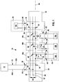
- Figure 1 illustrates a modular control system 10 for transmitting power and data between a control processor 12 that receives and transmits signals along trunk 14 and field devices 16a, 16b, 16c, and 16d. Each field device 16a-c is located in a hazardous area 18. Field device 16d is located in a safe area 20.
- the illustrated control system 10 is a fieldbus system.
- the control system 10 is connected between the trunk 14 and the field devices 16 and transmits power from the trunk 14 to the field devices 16 and transmits data signals between the trunk 14 and the field devices 16.
- the field devices 16 may be process controllers, measurement devices, and the like as is well known in the art.
- Attached to the backplane 24 are a number of field modules 30a, 30b, and 30c.
- Each field module 30 forms an intrinsically safe connection to a respective field device 16 located in the hazardous area 18.
- an additional field module 32 that forms a non-intrinsically safe connection to the field device 16d located in the safe zone 20.
- Each of the illustrated field modules 30a, 30b, and 30c includes a different type of intrinsically safe connection 52.
- Field device 30a has an energy-limiting connection 52 that includes a fuse 54.
- the field device 30c has an optical isolation connection 52 incorporating an optical isolator 58. If desired, the device interface of the optically-isolated field device 30c can be configured to connect with fiber optic cable that extends to the field device for data signal transmission. Separate power leads can be provided that extends from the device interface 48 to the field device or the field device can be powered independently and not through the backplane 24.
- Segment protectors can also be provided for the energy limited modules if desired.
- the illustrated field module 32 is a "single spur” device, that is, the field module 32 connects to a single field device.
- the field module 32 can be a "multiple spur” device that can connect with two, three, four, or perhaps more field devices. Each device should be protected with its own respective segment protector.
- the trunk module 22, the intrinsically-safe field modules 30 and the non-intrinsically safe field modules 32 are preferably designed to resist and prevent sparking due to voltage creep between the field device interface 48 of an intrinsically safe field module 30 and either the trunk interface of the trunk module 22 or the field device interface 64 of a non-intrinsically safe field module 32.
- the trunk module 22 and the field modules 30, 32 are arranged in a side-by-side layout and extend along a horizontal axis 68 defined by the rail 34.
- the set of terminals 40 of the trunk module 22 and each set of terminals 66 of a non-intrinsically safe field module 32 is located on upper vertical ends of the trunk module 22 or the field module 32.
- the set of terminals 50 of an intrinsically safe field modules 30 is located on the vertical lower end of the field module 32.
- the intrinsically-safe terminals 50 are spaced away from the non-intrinsically-safe terminals 40 and 66.
- the backplane 24 can be an elongate printed circuit board, or can be formed as conductors that extend along the rail 34.
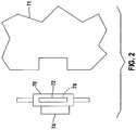
- the backplane 24 is formed as separable bus segments 70. See Figure 2 , which illustrates a backplane segment 70 and part of a housing portion 71 of a module 22, 30, or 36 attachable to the backplane segment 70.
- the backplane segment 70 snaps on the rail 34.
- Each backplane segment 70 includes a length of the backplane bus 24 and a connector 72 that forms part of the backplane interface for the trunk module 22 or field module 30, 32 to be attached to the backplane segment.
- Backplane bus connections 74 and 76 are located on one side and the bottom of the backplane segment 70.
- Backplane segments 70 are snapped on the rail 34 and pushed together to connect adjacent bus connectors and form the backplane 24 extending the length of the attached segments 70. Removing the housing portion 71 of a field module 30, 32 attached to the backplane segment leaves the segment 70 left behind on the rail 34 interconnected with adjacent segments, with the backplane 24 and the remaining modules intact and operational.
- a new module can be added to the system 10 by snapping a backplane segment 70 on the rail 34, pushing the added segment against the other backplane segments, and attaching the housing 71 of the module to the added backplane segment.
- the housing portion 71 includes the mating portion of the backplane interface and the remaining components of the module.
- a commercially available segmented backplane 70 that can be adapted for use in the present invention is the T-BUS (trademark) modular rail bus manufactured by Phoenix Contact, assignee of the present invention.
Applications Claiming Priority (2)
| Application Number | Priority Date | Filing Date | Title |
|---|---|---|---|
| US9323908P | 2008-08-29 | 2008-08-29 | |
| PCT/IB2009/006667 WO2010023545A1 (en) | 2008-08-29 | 2009-08-28 | Inherently safe modular control system |
Publications (2)
| Publication Number | Publication Date |
|---|---|
| EP2332227A1 EP2332227A1 (en) | 2011-06-15 |
| EP2332227B1 true EP2332227B1 (en) | 2018-09-26 |
Family
ID=41262139
Family Applications (1)
| Application Number | Title | Priority Date | Filing Date |
|---|---|---|---|
| EP09786188.4A Active EP2332227B1 (en) | 2008-08-29 | 2009-08-28 | Inherently safe modular control system |
Country Status (5)
| Country | Link |
|---|---|
| US (2) | US7940508B2 (ja) |
| EP (1) | EP2332227B1 (ja) |
| JP (1) | JP5693454B2 (ja) |
| CN (1) | CN102204052B (ja) |
| WO (1) | WO2010023545A1 (ja) |
Families Citing this family (13)
| Publication number | Priority date | Publication date | Assignee | Title |
|---|---|---|---|---|
| WO2010023545A1 (en) * | 2008-08-29 | 2010-03-04 | Phoenix Contact Development & Manufacturing, Inc. | Inherently safe modular control system |
| CN102356364A (zh) * | 2009-05-15 | 2012-02-15 | 费希尔-罗斯蒙德系统公司 | 具有增强功能的手持现场维护工具 |
| EP2430503B1 (en) | 2009-05-15 | 2017-11-22 | Fisher-Rosemount Systems, Inc. | Method of evaluating a potential location to add a wireless field device to an existing network |
| US8873241B2 (en) * | 2011-05-23 | 2014-10-28 | Honeywell International Inc. | Intrinsically safe serviceable transmitter apparatus and method |
| US20140143607A1 (en) | 2012-02-10 | 2014-05-22 | Phoenix Contact Development & Manufacturing, Inc. | Dedicated Network Diagnostics Module for a Process Network |
| US9270113B2 (en) * | 2012-08-27 | 2016-02-23 | Hamilton Sundstrand Corporation | Power distribution cabinet |
| WO2014047409A1 (en) * | 2012-09-21 | 2014-03-27 | Phoenix Contact Development and Manufacturing, Inc. | Voltage limiting device for use in a distributed control system |
| GB201304957D0 (en) * | 2013-03-19 | 2013-05-01 | Kitchener Renato | New generation fieldbus self organising power system |
| CN106165349B (zh) * | 2014-01-03 | 2020-06-19 | 凤凰通讯发展及制造股份有限公司 | 具有二线环路的现场总线网络 |
| WO2015168351A1 (en) | 2014-05-02 | 2015-11-05 | Swagelok Company | Fluid sample system and method |
| JP2017535189A (ja) * | 2014-10-15 | 2017-11-24 | フェニックス コンタクト ディベロップメント アンド マニュファクチャリング、インコーポレイテッド | フィールドバスネットワークにおけるスパー絶縁 |
| US10579027B2 (en) * | 2017-05-24 | 2020-03-03 | Honeywell International Inc. | Redundant universal IO modules with integrated galvanically isolated (GI) and intrinsically safe (IS) barriers |
| USD947699S1 (en) | 2019-03-11 | 2022-04-05 | Dometic Sweden Ab | Controller |
Citations (1)
| Publication number | Priority date | Publication date | Assignee | Title |
|---|---|---|---|---|
| US6700477B2 (en) * | 2000-05-22 | 2004-03-02 | Ceag Sicherheitstechnik Gmbh | Signal-transmission device |
Family Cites Families (18)
| Publication number | Priority date | Publication date | Assignee | Title |
|---|---|---|---|---|
| US4741031A (en) * | 1986-06-27 | 1988-04-26 | Gai-Tronics | Intrinsically safe telephone |
| SE466931B (sv) | 1990-08-29 | 1992-04-27 | Asea Brown Boveri | Processanpassningssystem |
| DE19512372A1 (de) * | 1995-04-01 | 1996-10-10 | Abb Patent Gmbh | Einrichtung zur eigensicheren Signalanpassung |
| JP3067604B2 (ja) * | 1995-08-25 | 2000-07-17 | 株式会社日立製作所 | 本質安全防爆バリア及びフィールドバスシステム |
| DE19742716C5 (de) * | 1997-09-26 | 2005-12-01 | Phoenix Contact Gmbh & Co. Kg | Steuer- und Datenübertragungsanlage und Verfahren zum Übertragen von sicherheitsbezogenen Daten |
| US6686831B2 (en) * | 2001-01-23 | 2004-02-03 | Invensys Systems, Inc. | Variable power control for process control instruments |
| US7684167B2 (en) * | 2003-09-30 | 2010-03-23 | Fisher-Rosemount Systems, Inc. | Communication bus suitable for use in a hazardous area of a process plant |
| DE10353950C5 (de) * | 2003-11-18 | 2013-10-24 | Phoenix Contact Gmbh & Co. Kg | Steuerungssystem |
| EP1721224B1 (en) * | 2004-03-02 | 2011-03-02 | Rosemount, Inc. | Field-mounted process device with programmable digital/analog interface |
| CN2774024Y (zh) * | 2004-11-26 | 2006-04-19 | 浙江中科正方电子技术有限公司 | 一种汽车车身can总线控制系统 |
| GB0514906D0 (en) | 2005-07-21 | 2005-08-24 | Rogoll Gunther | Modular segment protector |
| US7371091B2 (en) * | 2006-06-22 | 2008-05-13 | Honeywell International, Inc. | Method and apparatus for integrated hot swap connector pins for AC and DC electric power systems |
| US7663350B2 (en) * | 2006-07-13 | 2010-02-16 | Endress + Hauser Flowtec Ag | External electrical energy supply for field device |
| EP1885085B1 (de) * | 2006-08-01 | 2013-03-06 | Siemens Aktiengesellschaft | Berührungslose Energie- und Datenversorgung von Busteilnehmern |
| US8332567B2 (en) * | 2006-09-19 | 2012-12-11 | Fisher-Rosemount Systems, Inc. | Apparatus and methods to communicatively couple field devices to controllers in a process control system |
| EP1965482B1 (de) * | 2007-02-27 | 2010-06-30 | Siemens Aktiengesellschaft | ASI-Netzwerk für explosionsgefährdete Bereiche |
| GB0709824D0 (en) * | 2007-05-23 | 2007-07-04 | Kitchener Renato | Intrinsically safe power and communication |
| WO2010023545A1 (en) * | 2008-08-29 | 2010-03-04 | Phoenix Contact Development & Manufacturing, Inc. | Inherently safe modular control system |
-
2009
- 2009-08-28 WO PCT/IB2009/006667 patent/WO2010023545A1/en active Application Filing
- 2009-08-28 EP EP09786188.4A patent/EP2332227B1/en active Active
- 2009-08-28 US US12/549,474 patent/US7940508B2/en active Active
- 2009-08-28 JP JP2011524472A patent/JP5693454B2/ja active Active
- 2009-08-28 CN CN200980138251.3A patent/CN102204052B/zh active Active
- 2009-08-28 US US13/061,332 patent/US20110234003A1/en not_active Abandoned
Patent Citations (1)
| Publication number | Priority date | Publication date | Assignee | Title |
|---|---|---|---|---|
| US6700477B2 (en) * | 2000-05-22 | 2004-03-02 | Ceag Sicherheitstechnik Gmbh | Signal-transmission device |
Also Published As
| Publication number | Publication date |
|---|---|
| EP2332227A1 (en) | 2011-06-15 |
| US7940508B2 (en) | 2011-05-10 |
| JP5693454B2 (ja) | 2015-04-01 |
| US20110234003A1 (en) | 2011-09-29 |
| WO2010023545A1 (en) | 2010-03-04 |
| US20100222936A1 (en) | 2010-09-02 |
| CN102204052B (zh) | 2014-07-16 |
| JP2012510093A (ja) | 2012-04-26 |
| CN102204052A (zh) | 2011-09-28 |
Similar Documents
| Publication | Publication Date | Title |
|---|---|---|
| EP2332227B1 (en) | Inherently safe modular control system | |
| JP2012510093A5 (ja) | ||
| JP5101624B2 (ja) | パワーレールシステム | |
| EP2624375B1 (en) | Power distribution system | |
| JP2002330506A (ja) | 分電盤、ジャンクションボックス、アウトレットボックス、電気コード付きプラグ、アウトレットボックス用端子盤、テーブルタップ及び宅内ネットワークシステム | |
| EP2531698B1 (en) | Intrinsically safe connection unit with a network interface, intrinsically safe appliance and network interface for it | |
| US9564707B2 (en) | Connection system with modular expansion units having two or more devices | |
| CN113574914A (zh) | 具有用于现场安装的接入点天线的集成本质安全输出的无线传感器网络网关 | |
| EP3831173B1 (en) | Power distribution unit with a modular construction | |
| EP2147520B1 (en) | Intrinsically safe dsl circuit | |
| US20150180226A1 (en) | Multispur fieldbus isolator arrangement | |
| EP1905056A1 (en) | Modular fieldbus segment protector | |
| KR100985727B1 (ko) | 이상 감시 기능을 갖는 비상 전원 공급 장치 및 이를 포함하는 일체형 수배전반 | |
| WO2007052040A1 (en) | An assembly for permitting power-over-ethernet connection | |
| Cisco | Installing the Cisco ONS 15104 | |
| Cisco | Preparing for Installation and Network Connections | |
| RU2714025C1 (ru) | Контролирующий пункт ввода-вывода дискретных сигналов | |
| Wieland et al. | Internet | |
| JPH1079745A (ja) | 光通信ケーブルおよびこれを用いたlanシステム | |
| CN103210611A (zh) | 建筑系统工程中具有通用型数据耦合的安装设备以及具有如此构造的安装设备的装置 |
Legal Events
| Date | Code | Title | Description |
|---|---|---|---|
| PUAI | Public reference made under article 153(3) epc to a published international application that has entered the european phase |
Free format text: ORIGINAL CODE: 0009012 |
|
| 17P | Request for examination filed |
Effective date: 20110328 |
|
| AK | Designated contracting states |
Kind code of ref document: A1 Designated state(s): AT BE BG CH CY CZ DE DK EE ES FI FR GB GR HR HU IE IS IT LI LT LU LV MC MK MT NL NO PL PT RO SE SI SK SM TR |
|
| AX | Request for extension of the european patent |
Extension state: AL BA RS |
|
| DAX | Request for extension of the european patent (deleted) | ||
| 17Q | First examination report despatched |
Effective date: 20141212 |
|
| GRAP | Despatch of communication of intention to grant a patent |
Free format text: ORIGINAL CODE: EPIDOSNIGR1 |
|
| STAA | Information on the status of an ep patent application or granted ep patent |
Free format text: STATUS: GRANT OF PATENT IS INTENDED |
|
| INTG | Intention to grant announced |
Effective date: 20180418 |
|
| RIN1 | Information on inventor provided before grant (corrected) |
Inventor name: KREIDER, AARON, RICHARD Inventor name: HELFRICK, BRENTON, EUGENE Inventor name: MATHEWS, DAVIS Inventor name: VOGT, BRIAN, JAMES |
|
| GRAS | Grant fee paid |
Free format text: ORIGINAL CODE: EPIDOSNIGR3 |
|
| GRAA | (expected) grant |
Free format text: ORIGINAL CODE: 0009210 |
|
| STAA | Information on the status of an ep patent application or granted ep patent |
Free format text: STATUS: THE PATENT HAS BEEN GRANTED |
|
| AK | Designated contracting states |
Kind code of ref document: B1 Designated state(s): AT BE BG CH CY CZ DE DK EE ES FI FR GB GR HR HU IE IS IT LI LT LU LV MC MK MT NL NO PL PT RO SE SI SK SM TR |
|
| REG | Reference to a national code |
Ref country code: GB Ref legal event code: FG4D |
|
| REG | Reference to a national code |
Ref country code: CH Ref legal event code: EP |
|
| REG | Reference to a national code |
Ref country code: AT Ref legal event code: REF Ref document number: 1047160 Country of ref document: AT Kind code of ref document: T Effective date: 20181015 |
|
| REG | Reference to a national code |
Ref country code: IE Ref legal event code: FG4D |
|
| REG | Reference to a national code |
Ref country code: DE Ref legal event code: R096 Ref document number: 602009054762 Country of ref document: DE |
|
| REG | Reference to a national code |
Ref country code: NL Ref legal event code: MP Effective date: 20180926 |
|
| PG25 | Lapsed in a contracting state [announced via postgrant information from national office to epo] |
Ref country code: LT Free format text: LAPSE BECAUSE OF FAILURE TO SUBMIT A TRANSLATION OF THE DESCRIPTION OR TO PAY THE FEE WITHIN THE PRESCRIBED TIME-LIMIT Effective date: 20180926 Ref country code: BG Free format text: LAPSE BECAUSE OF FAILURE TO SUBMIT A TRANSLATION OF THE DESCRIPTION OR TO PAY THE FEE WITHIN THE PRESCRIBED TIME-LIMIT Effective date: 20181226 Ref country code: SE Free format text: LAPSE BECAUSE OF FAILURE TO SUBMIT A TRANSLATION OF THE DESCRIPTION OR TO PAY THE FEE WITHIN THE PRESCRIBED TIME-LIMIT Effective date: 20180926 Ref country code: GR Free format text: LAPSE BECAUSE OF FAILURE TO SUBMIT A TRANSLATION OF THE DESCRIPTION OR TO PAY THE FEE WITHIN THE PRESCRIBED TIME-LIMIT Effective date: 20181227 Ref country code: FI Free format text: LAPSE BECAUSE OF FAILURE TO SUBMIT A TRANSLATION OF THE DESCRIPTION OR TO PAY THE FEE WITHIN THE PRESCRIBED TIME-LIMIT Effective date: 20180926 Ref country code: NO Free format text: LAPSE BECAUSE OF FAILURE TO SUBMIT A TRANSLATION OF THE DESCRIPTION OR TO PAY THE FEE WITHIN THE PRESCRIBED TIME-LIMIT Effective date: 20181226 |
|
| REG | Reference to a national code |
Ref country code: LT Ref legal event code: MG4D |
|
| PG25 | Lapsed in a contracting state [announced via postgrant information from national office to epo] |
Ref country code: HR Free format text: LAPSE BECAUSE OF FAILURE TO SUBMIT A TRANSLATION OF THE DESCRIPTION OR TO PAY THE FEE WITHIN THE PRESCRIBED TIME-LIMIT Effective date: 20180926 Ref country code: LV Free format text: LAPSE BECAUSE OF FAILURE TO SUBMIT A TRANSLATION OF THE DESCRIPTION OR TO PAY THE FEE WITHIN THE PRESCRIBED TIME-LIMIT Effective date: 20180926 |
|
| REG | Reference to a national code |
Ref country code: AT Ref legal event code: MK05 Ref document number: 1047160 Country of ref document: AT Kind code of ref document: T Effective date: 20180926 |
|
| PG25 | Lapsed in a contracting state [announced via postgrant information from national office to epo] |
Ref country code: RO Free format text: LAPSE BECAUSE OF FAILURE TO SUBMIT A TRANSLATION OF THE DESCRIPTION OR TO PAY THE FEE WITHIN THE PRESCRIBED TIME-LIMIT Effective date: 20180926 Ref country code: CZ Free format text: LAPSE BECAUSE OF FAILURE TO SUBMIT A TRANSLATION OF THE DESCRIPTION OR TO PAY THE FEE WITHIN THE PRESCRIBED TIME-LIMIT Effective date: 20180926 Ref country code: IS Free format text: LAPSE BECAUSE OF FAILURE TO SUBMIT A TRANSLATION OF THE DESCRIPTION OR TO PAY THE FEE WITHIN THE PRESCRIBED TIME-LIMIT Effective date: 20190126 Ref country code: PL Free format text: LAPSE BECAUSE OF FAILURE TO SUBMIT A TRANSLATION OF THE DESCRIPTION OR TO PAY THE FEE WITHIN THE PRESCRIBED TIME-LIMIT Effective date: 20180926 Ref country code: AT Free format text: LAPSE BECAUSE OF FAILURE TO SUBMIT A TRANSLATION OF THE DESCRIPTION OR TO PAY THE FEE WITHIN THE PRESCRIBED TIME-LIMIT Effective date: 20180926 Ref country code: ES Free format text: LAPSE BECAUSE OF FAILURE TO SUBMIT A TRANSLATION OF THE DESCRIPTION OR TO PAY THE FEE WITHIN THE PRESCRIBED TIME-LIMIT Effective date: 20180926 Ref country code: NL Free format text: LAPSE BECAUSE OF FAILURE TO SUBMIT A TRANSLATION OF THE DESCRIPTION OR TO PAY THE FEE WITHIN THE PRESCRIBED TIME-LIMIT Effective date: 20180926 Ref country code: EE Free format text: LAPSE BECAUSE OF FAILURE TO SUBMIT A TRANSLATION OF THE DESCRIPTION OR TO PAY THE FEE WITHIN THE PRESCRIBED TIME-LIMIT Effective date: 20180926 |
|
| PG25 | Lapsed in a contracting state [announced via postgrant information from national office to epo] |
Ref country code: SM Free format text: LAPSE BECAUSE OF FAILURE TO SUBMIT A TRANSLATION OF THE DESCRIPTION OR TO PAY THE FEE WITHIN THE PRESCRIBED TIME-LIMIT Effective date: 20180926 Ref country code: PT Free format text: LAPSE BECAUSE OF FAILURE TO SUBMIT A TRANSLATION OF THE DESCRIPTION OR TO PAY THE FEE WITHIN THE PRESCRIBED TIME-LIMIT Effective date: 20190126 Ref country code: SK Free format text: LAPSE BECAUSE OF FAILURE TO SUBMIT A TRANSLATION OF THE DESCRIPTION OR TO PAY THE FEE WITHIN THE PRESCRIBED TIME-LIMIT Effective date: 20180926 |
|
| REG | Reference to a national code |
Ref country code: DE Ref legal event code: R097 Ref document number: 602009054762 Country of ref document: DE |
|
| PG25 | Lapsed in a contracting state [announced via postgrant information from national office to epo] |
Ref country code: DK Free format text: LAPSE BECAUSE OF FAILURE TO SUBMIT A TRANSLATION OF THE DESCRIPTION OR TO PAY THE FEE WITHIN THE PRESCRIBED TIME-LIMIT Effective date: 20180926 |
|
| PLBE | No opposition filed within time limit |
Free format text: ORIGINAL CODE: 0009261 |
|
| STAA | Information on the status of an ep patent application or granted ep patent |
Free format text: STATUS: NO OPPOSITION FILED WITHIN TIME LIMIT |
|
| 26N | No opposition filed |
Effective date: 20190627 |
|
| PG25 | Lapsed in a contracting state [announced via postgrant information from national office to epo] |
Ref country code: SI Free format text: LAPSE BECAUSE OF FAILURE TO SUBMIT A TRANSLATION OF THE DESCRIPTION OR TO PAY THE FEE WITHIN THE PRESCRIBED TIME-LIMIT Effective date: 20180926 |
|
| PG25 | Lapsed in a contracting state [announced via postgrant information from national office to epo] |
Ref country code: TR Free format text: LAPSE BECAUSE OF FAILURE TO SUBMIT A TRANSLATION OF THE DESCRIPTION OR TO PAY THE FEE WITHIN THE PRESCRIBED TIME-LIMIT Effective date: 20180926 |
|
| GBPC | Gb: european patent ceased through non-payment of renewal fee |
Effective date: 20190828 |
|
| PG25 | Lapsed in a contracting state [announced via postgrant information from national office to epo] |
Ref country code: LI Free format text: LAPSE BECAUSE OF NON-PAYMENT OF DUE FEES Effective date: 20190831 Ref country code: CH Free format text: LAPSE BECAUSE OF NON-PAYMENT OF DUE FEES Effective date: 20190831 Ref country code: LU Free format text: LAPSE BECAUSE OF NON-PAYMENT OF DUE FEES Effective date: 20190828 Ref country code: MC Free format text: LAPSE BECAUSE OF FAILURE TO SUBMIT A TRANSLATION OF THE DESCRIPTION OR TO PAY THE FEE WITHIN THE PRESCRIBED TIME-LIMIT Effective date: 20180926 |
|
| REG | Reference to a national code |
Ref country code: BE Ref legal event code: MM Effective date: 20190831 |
|
| PG25 | Lapsed in a contracting state [announced via postgrant information from national office to epo] |
Ref country code: IE Free format text: LAPSE BECAUSE OF NON-PAYMENT OF DUE FEES Effective date: 20190828 |
|
| PG25 | Lapsed in a contracting state [announced via postgrant information from national office to epo] |
Ref country code: GB Free format text: LAPSE BECAUSE OF NON-PAYMENT OF DUE FEES Effective date: 20190828 Ref country code: BE Free format text: LAPSE BECAUSE OF NON-PAYMENT OF DUE FEES Effective date: 20190831 |
|
| PG25 | Lapsed in a contracting state [announced via postgrant information from national office to epo] |
Ref country code: CY Free format text: LAPSE BECAUSE OF FAILURE TO SUBMIT A TRANSLATION OF THE DESCRIPTION OR TO PAY THE FEE WITHIN THE PRESCRIBED TIME-LIMIT Effective date: 20180926 |
|
| PG25 | Lapsed in a contracting state [announced via postgrant information from national office to epo] |
Ref country code: HU Free format text: LAPSE BECAUSE OF FAILURE TO SUBMIT A TRANSLATION OF THE DESCRIPTION OR TO PAY THE FEE WITHIN THE PRESCRIBED TIME-LIMIT; INVALID AB INITIO Effective date: 20090828 Ref country code: MT Free format text: LAPSE BECAUSE OF FAILURE TO SUBMIT A TRANSLATION OF THE DESCRIPTION OR TO PAY THE FEE WITHIN THE PRESCRIBED TIME-LIMIT Effective date: 20180926 |
|
| PG25 | Lapsed in a contracting state [announced via postgrant information from national office to epo] |
Ref country code: MK Free format text: LAPSE BECAUSE OF FAILURE TO SUBMIT A TRANSLATION OF THE DESCRIPTION OR TO PAY THE FEE WITHIN THE PRESCRIBED TIME-LIMIT Effective date: 20180926 |
|
| P01 | Opt-out of the competence of the unified patent court (upc) registered |
Effective date: 20230525 |
|
| P02 | Opt-out of the competence of the unified patent court (upc) changed |
Effective date: 20230530 |
|
| PGFP | Annual fee paid to national office [announced via postgrant information from national office to epo] |
Ref country code: IT Payment date: 20230822 Year of fee payment: 15 |
|
| PGFP | Annual fee paid to national office [announced via postgrant information from national office to epo] |
Ref country code: FR Payment date: 20230824 Year of fee payment: 15 |
|
| PGFP | Annual fee paid to national office [announced via postgrant information from national office to epo] |
Ref country code: DE Payment date: 20231027 Year of fee payment: 15 |