EP2331274B1 - Forming method and apparatus having a hydrostatic pressing medium - Google Patents
Forming method and apparatus having a hydrostatic pressing medium Download PDFInfo
- Publication number
- EP2331274B1 EP2331274B1 EP09790774A EP09790774A EP2331274B1 EP 2331274 B1 EP2331274 B1 EP 2331274B1 EP 09790774 A EP09790774 A EP 09790774A EP 09790774 A EP09790774 A EP 09790774A EP 2331274 B1 EP2331274 B1 EP 2331274B1
- Authority
- EP
- European Patent Office
- Prior art keywords
- workpiece
- temperature
- susceptor
- hydrostatic pressing
- temperatures
- Prior art date
- Legal status (The legal status is an assumption and is not a legal conclusion. Google has not performed a legal analysis and makes no representation as to the accuracy of the status listed.)
- Active
Links
- 238000003825 pressing Methods 0.000 title claims description 49
- 230000002706 hydrostatic effect Effects 0.000 title claims description 47
- 238000000034 method Methods 0.000 title claims description 40
- 239000012071 phase Substances 0.000 claims description 62
- 238000010438 heat treatment Methods 0.000 claims description 39
- 238000001816 cooling Methods 0.000 claims description 32
- 230000006698 induction Effects 0.000 claims description 31
- 230000009466 transformation Effects 0.000 claims description 29
- 239000000463 material Substances 0.000 claims description 25
- 239000011521 glass Substances 0.000 claims description 15
- 230000007423 decrease Effects 0.000 claims description 14
- 230000004044 response Effects 0.000 claims description 12
- 230000001351 cycling effect Effects 0.000 claims description 10
- 239000007788 liquid Substances 0.000 claims description 9
- 239000004020 conductor Substances 0.000 claims description 4
- 238000004891 communication Methods 0.000 claims description 2
- 239000007791 liquid phase Substances 0.000 claims description 2
- 239000000203 mixture Substances 0.000 description 11
- 229910052751 metal Inorganic materials 0.000 description 10
- 239000002184 metal Substances 0.000 description 10
- 229910045601 alloy Inorganic materials 0.000 description 9
- 239000000956 alloy Substances 0.000 description 9
- 238000012545 processing Methods 0.000 description 8
- 230000008859 change Effects 0.000 description 7
- 238000000576 coating method Methods 0.000 description 6
- 239000000843 powder Substances 0.000 description 6
- PXHVJJICTQNCMI-UHFFFAOYSA-N Nickel Chemical compound [Ni] PXHVJJICTQNCMI-UHFFFAOYSA-N 0.000 description 4
- 239000011248 coating agent Substances 0.000 description 4
- 238000007596 consolidation process Methods 0.000 description 4
- 239000002826 coolant Substances 0.000 description 4
- 230000005672 electromagnetic field Effects 0.000 description 4
- 238000001513 hot isostatic pressing Methods 0.000 description 4
- 239000007790 solid phase Substances 0.000 description 4
- 229910001069 Ti alloy Inorganic materials 0.000 description 3
- RTAQQCXQSZGOHL-UHFFFAOYSA-N Titanium Chemical compound [Ti] RTAQQCXQSZGOHL-UHFFFAOYSA-N 0.000 description 3
- 230000003247 decreasing effect Effects 0.000 description 3
- 230000005294 ferromagnetic effect Effects 0.000 description 3
- 238000007731 hot pressing Methods 0.000 description 3
- 230000005298 paramagnetic effect Effects 0.000 description 3
- 230000008569 process Effects 0.000 description 3
- HBMJWWWQQXIZIP-UHFFFAOYSA-N silicon carbide Chemical compound [Si+]#[C-] HBMJWWWQQXIZIP-UHFFFAOYSA-N 0.000 description 3
- 229910010271 silicon carbide Inorganic materials 0.000 description 3
- 239000010936 titanium Substances 0.000 description 3
- 229910052719 titanium Inorganic materials 0.000 description 3
- 230000007704 transition Effects 0.000 description 3
- 241000167857 Bourreria Species 0.000 description 2
- XEEYBQQBJWHFJM-UHFFFAOYSA-N Iron Chemical compound [Fe] XEEYBQQBJWHFJM-UHFFFAOYSA-N 0.000 description 2
- 238000000429 assembly Methods 0.000 description 2
- 230000000712 assembly Effects 0.000 description 2
- 230000008901 benefit Effects 0.000 description 2
- 239000010941 cobalt Substances 0.000 description 2
- 229910017052 cobalt Inorganic materials 0.000 description 2
- GUTLYIVDDKVIGB-UHFFFAOYSA-N cobalt atom Chemical compound [Co] GUTLYIVDDKVIGB-UHFFFAOYSA-N 0.000 description 2
- 239000003302 ferromagnetic material Substances 0.000 description 2
- 239000000835 fiber Substances 0.000 description 2
- 238000003780 insertion Methods 0.000 description 2
- 230000037431 insertion Effects 0.000 description 2
- 229910001092 metal group alloy Inorganic materials 0.000 description 2
- 239000007769 metal material Substances 0.000 description 2
- 229910052759 nickel Inorganic materials 0.000 description 2
- 229910000851 Alloy steel Inorganic materials 0.000 description 1
- VYZAMTAEIAYCRO-UHFFFAOYSA-N Chromium Chemical compound [Cr] VYZAMTAEIAYCRO-UHFFFAOYSA-N 0.000 description 1
- 229910000640 Fe alloy Inorganic materials 0.000 description 1
- 238000010521 absorption reaction Methods 0.000 description 1
- 239000000443 aerosol Substances 0.000 description 1
- 229910052782 aluminium Inorganic materials 0.000 description 1
- XAGFODPZIPBFFR-UHFFFAOYSA-N aluminium Chemical compound [Al] XAGFODPZIPBFFR-UHFFFAOYSA-N 0.000 description 1
- PNEYBMLMFCGWSK-UHFFFAOYSA-N aluminium oxide Inorganic materials [O-2].[O-2].[O-2].[Al+3].[Al+3] PNEYBMLMFCGWSK-UHFFFAOYSA-N 0.000 description 1
- 230000015572 biosynthetic process Effects 0.000 description 1
- 239000000919 ceramic Substances 0.000 description 1
- 229910010293 ceramic material Inorganic materials 0.000 description 1
- 238000001311 chemical methods and process Methods 0.000 description 1
- 229910052804 chromium Inorganic materials 0.000 description 1
- 239000011651 chromium Substances 0.000 description 1
- 238000010276 construction Methods 0.000 description 1
- 230000008602 contraction Effects 0.000 description 1
- 238000007796 conventional method Methods 0.000 description 1
- 125000004122 cyclic group Chemical group 0.000 description 1
- 238000001514 detection method Methods 0.000 description 1
- 238000010586 diagram Methods 0.000 description 1
- 229910001026 inconel Inorganic materials 0.000 description 1
- 230000001939 inductive effect Effects 0.000 description 1
- 238000001764 infiltration Methods 0.000 description 1
- 230000008595 infiltration Effects 0.000 description 1
- 238000009413 insulation Methods 0.000 description 1
- 230000003993 interaction Effects 0.000 description 1
- 229910000765 intermetallic Inorganic materials 0.000 description 1
- 229910052742 iron Inorganic materials 0.000 description 1
- 230000005291 magnetic effect Effects 0.000 description 1
- 239000011159 matrix material Substances 0.000 description 1
- 238000010297 mechanical methods and process Methods 0.000 description 1
- 230000005226 mechanical processes and functions Effects 0.000 description 1
- 238000002844 melting Methods 0.000 description 1
- 230000008018 melting Effects 0.000 description 1
- 150000001247 metal acetylides Chemical class 0.000 description 1
- 150000002739 metals Chemical class 0.000 description 1
- 239000003595 mist Substances 0.000 description 1
- 238000012986 modification Methods 0.000 description 1
- 230000004048 modification Effects 0.000 description 1
- 239000006060 molten glass Substances 0.000 description 1
- 150000004767 nitrides Chemical class 0.000 description 1
- 239000002245 particle Substances 0.000 description 1
- 230000008707 rearrangement Effects 0.000 description 1
- 238000007493 shaping process Methods 0.000 description 1
- 239000010935 stainless steel Substances 0.000 description 1
- 229910001220 stainless steel Inorganic materials 0.000 description 1
- 239000010959 steel Substances 0.000 description 1
- 239000000126 substance Substances 0.000 description 1
- 238000005382 thermal cycling Methods 0.000 description 1
- 229910052720 vanadium Inorganic materials 0.000 description 1
- GPPXJZIENCGNKB-UHFFFAOYSA-N vanadium Chemical compound [V]#[V] GPPXJZIENCGNKB-UHFFFAOYSA-N 0.000 description 1
Images


Classifications
-
- B—PERFORMING OPERATIONS; TRANSPORTING
- B21—MECHANICAL METAL-WORKING WITHOUT ESSENTIALLY REMOVING MATERIAL; PUNCHING METAL
- B21D—WORKING OR PROCESSING OF SHEET METAL OR METAL TUBES, RODS OR PROFILES WITHOUT ESSENTIALLY REMOVING MATERIAL; PUNCHING METAL
- B21D37/00—Tools as parts of machines covered by this subclass
- B21D37/16—Heating or cooling
-
- B—PERFORMING OPERATIONS; TRANSPORTING
- B21—MECHANICAL METAL-WORKING WITHOUT ESSENTIALLY REMOVING MATERIAL; PUNCHING METAL
- B21D—WORKING OR PROCESSING OF SHEET METAL OR METAL TUBES, RODS OR PROFILES WITHOUT ESSENTIALLY REMOVING MATERIAL; PUNCHING METAL
- B21D26/00—Shaping without cutting otherwise than using rigid devices or tools or yieldable or resilient pads, i.e. applying fluid pressure or magnetic forces
- B21D26/02—Shaping without cutting otherwise than using rigid devices or tools or yieldable or resilient pads, i.e. applying fluid pressure or magnetic forces by applying fluid pressure
- B21D26/021—Deforming sheet bodies
- B21D26/027—Means for controlling fluid parameters, e.g. pressure or temperature
-
- B—PERFORMING OPERATIONS; TRANSPORTING
- B21—MECHANICAL METAL-WORKING WITHOUT ESSENTIALLY REMOVING MATERIAL; PUNCHING METAL
- B21D—WORKING OR PROCESSING OF SHEET METAL OR METAL TUBES, RODS OR PROFILES WITHOUT ESSENTIALLY REMOVING MATERIAL; PUNCHING METAL
- B21D26/00—Shaping without cutting otherwise than using rigid devices or tools or yieldable or resilient pads, i.e. applying fluid pressure or magnetic forces
- B21D26/02—Shaping without cutting otherwise than using rigid devices or tools or yieldable or resilient pads, i.e. applying fluid pressure or magnetic forces by applying fluid pressure
- B21D26/021—Deforming sheet bodies
- B21D26/031—Mould construction
-
- B—PERFORMING OPERATIONS; TRANSPORTING
- B22—CASTING; POWDER METALLURGY
- B22F—WORKING METALLIC POWDER; MANUFACTURE OF ARTICLES FROM METALLIC POWDER; MAKING METALLIC POWDER; APPARATUS OR DEVICES SPECIALLY ADAPTED FOR METALLIC POWDER
- B22F3/00—Manufacture of workpieces or articles from metallic powder characterised by the manner of compacting or sintering; Apparatus specially adapted therefor ; Presses and furnaces
- B22F3/12—Both compacting and sintering
- B22F3/14—Both compacting and sintering simultaneously
- B22F3/15—Hot isostatic pressing
- B22F3/156—Hot isostatic pressing by a pressure medium in liquid or powder form
-
- Y—GENERAL TAGGING OF NEW TECHNOLOGICAL DEVELOPMENTS; GENERAL TAGGING OF CROSS-SECTIONAL TECHNOLOGIES SPANNING OVER SEVERAL SECTIONS OF THE IPC; TECHNICAL SUBJECTS COVERED BY FORMER USPC CROSS-REFERENCE ART COLLECTIONS [XRACs] AND DIGESTS
- Y10—TECHNICAL SUBJECTS COVERED BY FORMER USPC
- Y10T—TECHNICAL SUBJECTS COVERED BY FORMER US CLASSIFICATION
- Y10T29/00—Metal working
- Y10T29/49—Method of mechanical manufacture
- Y10T29/49805—Shaping by direct application of fluent pressure
Definitions
- Embodiments of the present invention relate generally to methods and apparatus for forming a workpiece having a desired configuration and, more particularly, to methods and apparatus for forming a workpiece which include a hydrostatic pressing medium in order to provide relatively even pressure across the surface of the workpiece, including a workpiece having a complex shape.
- an apparatus for consolidating a workpiece may include first and second dies which cooperate to define an internal cavity.
- a susceptor may line the internal cavity and, in turn, define a die cavity for receiving the workpiece.
- the susceptor is formed of a conductive material, while the first and second dies are formed of a material transparent to electromagnetic energy.
- an induction heating coil is positioned proximate the first and second dies for generating electromagnetic energy, such as an oscillating electromagnetic field. Since the first and second dies are transparent to the electromagnetic energy, the electromagnetic energy travels through the dies and interacts with the susceptor, thereby rapidly heating the susceptor. Since the workpiece is in thermal contact with the susceptor, the heating of the susceptor also serves to heat the workpiece.
- Susceptors may be referred to as smart susceptors because the material composition of the susceptor is specifically chosen to produce a set temperature point when used in an induction processing system.
- the material composition of the susceptor may be chosen such that the Curie point of the susceptor at which there is a transition between the ferromagnetic and paramagnetic phases of the material forming the susceptor is used to set the equilibrium temperature point to which the susceptor is inductively heated.
- a forming technique has been developed to take advantage of the unique properties of metallic materials when the crystallographic characteristics of the metallic materials are changing.
- a workpiece such as a preform
- An induction heating coil can then be energized so as to generate an oscillating electromagnetic field which heats the susceptor and, in turn, the workpiece to a temperature proximate the phase transformation temperature rangeover which one solid phase of the workpiece changes completely to a second solid phase.
- the temperature of the workpiece is then repeatedly cycled above and below the phase transformation temperature range in order to consolidate the workpiece.
- JP 56126032 discloses an apparatus and method for forming a workpiece having a desired configuration by means of a hydrostatic pressing medium.
- US-A-3516274 discloses a method and device for shaping metal, by pressing the workpiece between a bed of semi-molten glass and a die.
- the present invention provides an apparatus according to claim 1 and a method for forming a workpiece according to claim 10.
- a method and apparatus for forming a workpiece having a desired configuration as well as an associated preform assembly are provided in accordance with embodiments of the present invention.
- the forming method and apparatus as well as the preform assembly include a hydrostatic pressing medium disposed within the die cavity proximate to at least one side of the workpiece.
- the hydrostatic pressing medium is configured to be liquid having a relatively high viscosity at the temperatures at which the workpiece is processed, thereby facilitating the relatively even application of pressure to the workpiece.
- embodiments of the present invention permit a workpiece having a complex configuration to be formed utilizing a single acting die so as to reduce the complexity and cost of the die assembly relative to other die assemblies that require double or triple acting dies.
- An apparatus for forming a workpiece having a desired configuration.
- the apparatus includes first and second co-operable dies as well as a susceptor formed of a conductive material.
- the first and second co-operable dies and the susceptor are configured to define a die cavity for receiving the workpiece and defining the desired configuration of the workpiece.
- the susceptor is in thermal communication with the die cavity and, more particularly, with the workpiece disposed within the die cavity, so as to repeatedly cycle the workpiece between a first temperature above a phase transus temperature of the workpiece and a second temperature below the phase transus temperature of the workpiece.
- the apparatus according to the invention also includes a hydrostatic pressing medium disposed within the die cavity so as to be proximate at least one side of the workpiece.
- the hydrostatic pressing medium is configured to be a liquid having a viscosity of approximately 10 3 poise (10 3 decipascal-sec) in the cycled temperature range.
- the hydrostatic pressing medium may be an amorphous material, such as glass.
- a hydrostatic pressing medium is also generally non-reactive with the workpiece at temperatures between the first and second temperatures.
- the hydrostatic pressing medium, such as glass may be configured to encapsulate the workpiece.
- the hydrostatic pressing medium, such as glass may also be carried by the workpiece, such as a coating on one or all surfaces of the workpiece.
- the apparatus may also include a controller configured to control the cyclic heating and cooling of the workpiece.
- the controller may be configured to determine that the workpiece is at the second temperature below the phase transus temperature of the workpiece by detecting that a cooling rate of the workpiece has returned to a more rapid cooling rate following a decrease in the cooling rate within and/or below the phase transformation temperature range and to then cause the workpiece to be heated in response to the determination that the workpiece is at the second temperature.
- the controller may also be configured to determine that the workpiece is at the first temperature above the phase transus temperature of the workpiece by detecting that the susceptor has reached the Curie temperature and to then cause a workpiece to be cooled in response to a determination that the workpiece is at the first temperature range.
- the apparatus may also include a power supply and an induction heating coil that is configured to emit electromagnetic energy to heat the susceptor and, in turn, the workpiece.
- the controller is configured to determine that the workpiece is at the first temperature above the phase transus temperature range by detecting a completion of a decrease in the current level provided by the power supply to the induction heating coil.
- the hydrostatic pressing medium can facilitate the relatively even application of pressure to all surfaces of the workpiece.
- the apparatus of one embodiment need only include a single acting die in order to form the workpiece to the desired configuration. As such, the complexity and cost of the die relative to double or triple acting dies may be reduced.
- a method for forming a workpiece having a desired configuration according to the invention includes positioning the workpiece within a die cavity defined by a die assembly.
- the die cavity defines the desired configuration of the workpiece.
- a hydrostatic pressing medium such as glass, is also disposed within the die cavity so as to be proximate at least one side of the workpiece.
- the method also repeatedly cycles the workpiece between the first temperature above the phase transus temperature of the workpiece and the second temperature below the phase transus temperature of the workpiece.
- the method further applies pressure to the workpiece and the hydrostatic pressing medium concurrent with the repeated cycling of the workpiece between the first and second temperatures.
- the hydrostatic pressing medium remains in a liquid phase with a viscosity greater than approximately 10 3 poise (10 3 decipascal-sec) while repeatedly cycling the workpiece between the first and second temperatures.
- the method may determine that the workpiece is at the second temperature below the phase transus temperature of the workpiece by detecting that a cooling rate of the workpiece has returned a more rapid cooling rate following a decrease in the cooling rate within and/or above the phase transformation temperature range and may then heat the workpiece in response to the determination that the workpiece is at the second temperature.
- the method may also determine that the workpiece is at the first temperature above the phase transus temperature of the workpiece by detecting that the susceptor has reached the Curie temperature and may then cause the workpiece to be cooled in response to a determination that the workpiece is at the first temperature.
- the determination that the workpiece is at the first temperature above the phase transus temperature may include the detection of a completion of a decrease in a current level provided by the power supply to the induction heating coil.
- the hydrostatic pressing medium facilitates the relatively even application of pressure to the workpiece.
- workpieces having even a complex configuration may be formed with a single acting die, thereby reducing the complexity and cost of the die assembly relative to die assemblies including double or triple acting dies.
- the apparatus includes a die assembly including two or more dies 12, such as the first and second co-operable dies as shown in Figure 1 .
- the dies are typically formed of a strong and rigid material relative to the workpiece 14 and are also formed of a material having a melting point well above the processing temperature of the workpiece. Additionally, the dies can be formed of a material characterized by a low thermal expansion, high thermal insulation, and a low electromagnetic absorption.
- each of the dies may include multiple stacked metal sheets, such as stainless steel sheets or sheets formed of an Inconel(R) 625 alloy, which are trimmed to the appropriate dimensions for the induction coils (described below).
- the stacked metal sheets may be oriented in generally perpendicular relationship with respect to the respective contoured die surfaces.
- Each metal sheet may have a thickness of from about 1.6 mm (1/16") to about 6.4 mm (1/4"), for example and preferably about 5.080 mm (0.200").
- An air gap may be provided between adjacent stacked metal sheets to facilitate cooling of the dies, such as a gap of about 3.81mm (0.15").
- the stacked metal sheets may be attached to each other using clamps (not shown), fasteners (not shown) and/or other suitable technique known to those skilled in the art.
- the stacked metal sheets may be selected based on their electrical and thermal properties and may be transparent to the magnetic field.
- An electrically insulating coating (not shown) may optionally be provided on each side of each stacked sheet to prevent flow of electrical current between the stacked metal sheets.
- the insulating coating may be a material such as a ceramic material, for example.
- Multiple thermal expansion slots may be provided in the dies to facilitate thermal expansion and contraction of the stacked tooling apparatus 10.
- the die assembly can also include two or more strongbacks 13 to which the dies 12 are mounted.
- the first and second dies may be mounted to and supported by first and second strongbacks, respectively.
- a strongback is a stiff plate, such as a metal plate, that acts as a mechanical constraint to keep the dies together and to maintain the dimensional accuracy of the dies.
- the die assembly also generally includes an actuator, shown generically as 15 in Figure 1 , for controllably moving the dies toward and away from one another, such as by moving the dies toward one another so as to apply a predetermined amount of pressure to the workpiece 14.
- actuators may be employed including, for example, hydraulic, pneumatic or electric rams.
- the dies 12 define an internal cavity.
- the internal cavity defined by the dies may serve as the die cavity in which the workpiece is disposed.
- the apparatus 10 for forming a workpiece includes one or more induction coils 16 that extend through the dies to facilitate selective heating of the dies.
- a thermal control system may be connected to the induction coils.
- a susceptor may be thermally coupled to the induction coils of each die.
- Each susceptor may be a thermally-conductive material such as a ferromagnetic material, cobalt or nickel, for example.
- Each susceptor may generally conform to the first contoured die surface of the respective die.
- Electrically and thermally insulative coatings 17, i.e., die liners, may be provided on the contoured die surfaces of the dies 12.
- the electrically and thermally insulative coating may be, for example, alumina or silicon carbide and, more particularly, a SiC matrix with SiC fibers.
- the susceptors may, in turn, be provided on the electrically and thermally insulative coatings of the respective dies.
- a cooling system may be provided in each die.
- the cooling system may include, for example, coolant conduits which have a selected distribution throughout each die.
- the coolant conduit may be adapted to discharge a cooling medium into the respective die.
- the cooling medium may be a liquid, gas or gas/liquid mixture which may be applied as a mist or aerosol, for example.
- the susceptor 18 is responsive to electromagnetic energy, such as an oscillating electromagnetic field, generated by the induction heating coils 16. In response to the electromagnetic energy generated by the induction heating coils, the susceptor is heated which, in turn, heats the workpiece 14.
- electromagnetic energy such as an oscillating electromagnetic field
- the susceptor is heated which, in turn, heats the workpiece 14.
- induction heating techniques can more quickly heat and cool a workpiece in a controlled fashion as a result of the relatively rapid heating and cooling of the susceptor. For example, some induction heating techniques can heat and cool a workpiece about two orders of magnitude more quickly than conventional autoclave or hot isostatic pressing (HIP) processes.
- HIP hot isostatic pressing
- the susceptor is formed of ferromagnetic materials including a combination of iron, nickel, chromium and/or cobalt with the particular material composition chosen to produce a set temperature point to which the susceptor is heated in response to the electromagnetic energy generated by an induction heating coil.
- the susceptor may be constructed such that the Curie point of the susceptor at which there is a transition between the ferromagnetic and paramagnetic phases of the material defines the set temperature point to which the susceptor is inductively heated.
- the susceptor may be constructed such that the Curie point is greater, albeit typically only slightly greater, than the phase transformation temperature of the workpiece.
- a workpiece 14 is disposed within the die cavity.
- the method and apparatus 10 of embodiments of the present invention can form workpieces to have a desired complex configuration in which different portions of the workpiece extend in different directions.
- the method and apparatus of embodiments of the present invention can form workpieces having any desired configuration.
- the method and apparatus of embodiments of the present invention can form workpieces for a wide variety of applications.
- the method and apparatus of embodiments of the present invention can form workpieces for aerospace, automotive, marine, construction, structural and many other applications.
- a connector plate 30 for connecting a floor beam to the fuselage of an aircraft is formed and depicts one example of a complexly configured workpiece that can be formed in accordance with embodiments of the method and apparatus of the present invention.
- the workpiece 14 may also be formed of a variety of materials, but is typically formed of a metal alloy that experiences a phase change between two solid phases at an elevated temperature and pressure, that is, at a temperature and pressure greater than ambient temperature and pressure and, typically, much greater than ambient temperature and pressure.
- the metal alloy forming the workpiece may be a steel or iron alloy.
- the workpiece is formed of a titanium alloy, such as Ti-6-4 formed of 6% (weight percent) aluminum, 4% (weight percent) vanadium and 90% (weight percent) titanium.
- Ti-6-4 Under equilibrium conditions at room temperature, Ti-6-4 contains two solid phases, that is, a hexagonal close-packed phase, termed the alpha phase, which is more stable at lower temperatures and a body-centered cubic phase, termed the beta phase, which is more stable at higher temperatures.
- Ti-6-4 is a mixture of the beta phase and the alpha phase with the relative amount of each phase being determined by thermodynamics. As the temperature is increased, the alpha phase transforms to the beta phase over a phase transformation temperature range until the alloy becomes entirely formed of the beta phase at temperatures above the beta transus temperature.
- the beta transus temperature is approximately 1000°C.
- the Ti-6-4 will gradually change from the beta phase to the alpha phase as the temperature is decreased below the beta transus temperature over a phase transformation range. While for titanium alloys, the transformation from the hexagonal close packed phase to the body centered cubic phase occurs over a temperature range, for pure titanium, the transformation occurs at a single temperature value, about 880°C. Reference herein to a phase transformation temperature range includes both a range including a plurality of temperatures as well as a single temperature value. Additionally, the beta transus temperature varies depending upon the exact composition of the alloys.
- the method and apparatus 10 for forming a workpiece in accordance with preferred embodiments of the present invention also employ a hydrostatic pressing medium 26 disposed within the die cavity so as to be proximate at least one side of the workpiece 14. While the hydrostatic pressing medium need only be proximate one side of the workpiece, the hydrostatic pressing medium may surround or encapsulate the workpiece so as to be proximate each size of the workpiece, as in the illustrated embodiment. While the hydrostatic pressing medium may be disposed within the die cavity prior to insertion of the workpiece so as to be distinct from the workpiece, the hydrostatic pressing medium may be coated or otherwise disposed upon the workpiece prior to the insertion of the workpiece into the die cavity such that the workpiece carries the hydrostatic pressing medium.
- the hydrostatic pressing medium 26 is configured to be a liquid having a relatively high viscosity at the processing pressure and temperatures at which the method and apparatus 10 of embodiments of the present invention consolidate the workpiece 14.
- the viscosity of the liquid may be at or close to the working point within the phase transformation temperature range.
- the viscosity may range from ⁇ 10 3 poise to ⁇ 10 6 poise for temperatures within the phase transformation temperature range.
- the liquid generally has a low heat capacity, is transparent to radiant energy, is electrically nonconductive and has a relatively high thermal conductivity.
- the hydrostatic pressing medium may be an amorphous material, such as glass. Additionally, the hydrostatic pressing medium is advantageously non-reactive with the workpiece at the elevated temperatures at which the workpiece will be processed and consolidated.
- the hydrostatic pressing medium 26 may be formed of two layers of glass - a first layer proximate the preform and a second layer on the opposite side of the first layer from the preform such that the second layer is spaced from the preform by the first layer.
- the first layer is typically stiffer than the second layer, thereby reducing the infiltration of the glass into voids in the workpiece 14.
- a workpiece is positioned within the die cavity defined by a die assembly including, for example, the first and second co-operable dies 12. As described above, the die cavity defines the desired configuration of the workpiece.
- a preform of the workpiece may be initially formed. See block 40. The preform may have a shape that approximates the desired configuration of the workpiece even though the preform has not been fully consolidated.
- the preform is formed by placing the material from which the workpiece will be formed in a die and then pressing the material in a relatively cold state, such as at room temperature.
- This die also defines a die cavity in which the material is disposed and which has a shape which approximates the desired configuration of the resulting workpiece.
- the preform is formed from powder which may be mixed and blended to define the desired alloy, such as Ti-6-4.
- a preform indeed a near net preform in one embodiment, may be produced in which the powder is preconsolidated to have a shape which approximates the desired configuration of the resulting workpiece 14.
- a layer of the hydrostatic pressing medium 26, such as glass may be applied to at least one side or, in one embodiment, all surfaces of the preform. See block 42.
- the hydrostatic pressing medium is glass
- the glass may be applied to the preform by being spun on. Thereafter, the preform having the hydrostatic pressing medium applied thereto may be loaded into the die cavity as described above.
- a predetermined amount of pressure such as between about 1.5 KSI and 2.5 KSI for Ti-6-4 powder alloys, is applied to the workpiece. See block 46.
- a predetermined amount of pressure such as between about 1.5 KSI and 2.5 KSI for Ti-6-4 powder alloys.
- embodiments of the present invention may operate at lower pressures, such as pressures that are an order of magnitude lower, than conventional autoclave and HIP processes.
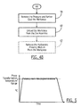
- the workpiece is repeatedly cycled between a first temperature above the beta transus temperature of the workpiece and a second temperature below the beta transus temperature of the workpiece.
- Figure 5 depicts the phase transformation temperature range of the workpiece across which the workpiece transitions between the alpha and beta phases.
- the temperature of the workpiece is increased relatively rapidly to the first temperature above the beta transus temperature and is then repeatedly cycled between the first and second temperatures prior to the completion of the consolidation process in which the temperature of the workpiece is relatively rapidly decreased to room temperature.
- the method of one embodiment repeatedly cycles a workpiece formed of Ti-6-4 powder alloys between the first and second temperatures for about 90 minutes to about 150 minutes with each heating and cooling cycle requiring about 3 minutes to about 5 minutes.
- the time required for each cycle and, in turn, the overall time required to process a workpiece may vary in accordance with a number of factors, including the material forming the workpiece. As such, each heating and cooling cycle may be longer than 3-5 minutes and, in one embodiment, each heating and cooling cycle may require about 15 minutes to about 20 minutes.
- the first and second temperatures can be selected to be any temperature above and below, respectively, the beta transus temperature.
- the first and second temperatures are typically selected to be only slightly above and below, respectively, the beta transus temperature.
- the phase transformation temperature range will depend upon the precise material composition of the workpiece such that even for a particular type of alloy, the phase transformation temperature range may vary from one workpiece to another since the precise material composition may similarly vary.
- first and second temperatures for a workpiece formed of Ti-6-4 having a beta transus temperature of approximately 1000°C could be about 1010°C and 890°C, respectively
- the actual phase transformation temperature range of Ti-6-4 may vary somewhat depending upon the exact material composition of the workpiece.
- the first and second temperatures are defined by the actual processing characteristics associated with the workpiece 14.
- the cooling of the workpiece from the first temperature to the second temperature generally follows the stairstep-like pattern.
- the cooling rate of the workpiece is generally relatively rapid and constant from the first temperature to the upper bound of the phase transformation temperature range, i.e., the beta transus temperature, as shown at 70.
- the cooling rate slows significantly as shown at 72, prior to again resuming the same relatively rapid cooling rate as shown at 74 once the phase transformation is essentially complete.
- the apparatus 10 of one embodiment of the present invention may include a controller 22 configured to detect that the cooling rate of the workpiece has returned to a more rapid cooling rate following a decrease in the cooling rate within the phase transformation temperature range. See block 52.
- thermocouples may be employed to monitor the temperature of the workpiece and to provide an indication of the temperature to the controller for determination of the cooling rate.
- the controller will determine that the workpiece is at the second temperature below the phase transformation temperature range of the workpiece and, in turn, provide a command to cause the workpiece to again be heated. See block 56.
- the method and apparatus 10 of embodiments of the present invention can heat the workpiece 14 in various manners.
- induction heating techniques are employed in which a thermal control system drives an induction heating coils 16 to emit electromagnetic energy, such as an oscillating electromagnetic field, which heats the susceptor 18 which, in turn, heats the workpiece.
- electromagnetic energy such as an oscillating electromagnetic field
- the commands from the controller 22 of this embodiment to cause the workpiece to be heated actually command the thermal control system to drive the induction heating coils to emit electromagnetic energy.
- the thermal control system will maintain a constant voltage level and will provide a current to the induction heating coils sufficient to maintain the constant voltage level.
- the current provided by the thermal control system to the induction heating coils in order to maintain the predefined voltage level generally decreases from a first higher current level to a second lower current level 76 as the load created by the susceptor changes due to a change in the susceptor from the ferromagnetic phase to the paramagnetic phase upon the susceptor having reached the Curie point temperature. Since the susceptor is designed such that its Curie point temperature is above the beta transus temperature of the workpiece, the recognition that the susceptor is at the Curie point temperature as a result of the decrease of the current provided by the power supply to the induction heating coils in order to maintain the constant voltage level is also determinative of the workpiece being at the first temperature above the beta transus temperature..
- the controller is also configured to detect that the susceptor has reached the Curie temperature, such as by detecting a completion of the decrease in the current level provided by the power supply to the induction heating coil. See block 48.
- the controller of this embodiment advantageously receives signals indicative of the current provided by the power supply to the induction heating coil and can detect when the current falls below a predefined level or, in one embodiment, when the decrease in the current level has been completed, thereby indicating that the susceptor has reached the Curie temperature.
- the controller is configured to also determine that the workpiece is at the first temperature above the beta transus temperature and to then issue commands which cause the workpiece to be cooled. In this regard, the controller can issue commands to the power supply terminating the current supply to the induction heating coils which, in turn, terminates the generation of the electromagnetic energy which heated the susceptor and, in turn, the workpiece. See block 50.
- the workpiece may be consolidated in an efficient manner and at relatively lower temperatures and pressures than those required by conventional forming techniques.
- the workpiece may be consolidated in an efficient manner and at relatively lower temperatures and pressures than those required by conventional forming techniques.
- the workpiece By consolidating the workpiece at temperatures within and proximate the beta transus temperature, excessive transformation and interaction of phases in the growth of grains in the consolidated workpiece can be controlled.
- a wide variety of possible material compositions and forms can be fabricated that can be utilized to tailor physical mechanical behavior of the resulting workpiece. For example, at temperatures below 1,000°C, a number of metals and ceramic intermetallic compounds, such as oxides, nitrides, carbides, borides, etc. are stable in titanium and could be incorporated into a variety of titanium alloy compositions in the form of particles, fibers, whiskers, etc. to enhance or otherwise tailor the mechanical, electrical and/or thermal performance of the resulting consolidated workpiece.
- the temperature of the workpiece may be decreased, such as by no longer generating electromagnetic energy with the induction heating coils 16.
- the pressure applied by the die assembly can be removed and the dies 12 may be opened such that a consolidated workpiece may be removed from assembly. See blocks 58 and 60.
- the workpiece may then be processed, such as by a chemical or mechanical process, to remove the hydrostatic pressing medium, such as a glass layer. See block 62.
- the workpiece can then be machined, if necessary, to have the desired final configuration.
- the hydrostatic pressing medium 26 is configured to be a liquid having a relatively high viscosity, such as a viscosity greater than 10 3 .
- the pressure applied to the workpiece 14 during the thermal processing of the workpiece will be spread relatively evenly across the surface of the workpiece as a result of the hydrostatic properties of the hydrostatic pressing medium.
- the hydrostatic pressing medium permits workpieces having a complex configuration, such as workpieces having portions which extend in different directions to be formed with a single acting die, that is, a die assembly that applies pressure in one direction, such as the vertical direction in the embodiment of Figure 1 .
- workpieces having a complex configuration can be fabricated without requiring the complexity and expense of a double or triple acting die.
- the resulting consolidation of the workpiece can be performed in a uniform manner such that the resulting workpiece is relatively uniformly consolidated so as to enjoy the desired material properties.
Landscapes
- Engineering & Computer Science (AREA)
- Mechanical Engineering (AREA)
- Physics & Mathematics (AREA)
- Fluid Mechanics (AREA)
- Manufacturing & Machinery (AREA)
- Press Drives And Press Lines (AREA)
Applications Claiming Priority (2)
| Application Number | Priority Date | Filing Date | Title |
|---|---|---|---|
| US12/179,230 US7905128B2 (en) | 2008-07-24 | 2008-07-24 | Forming method and apparatus and an associated preform having a hydrostatic pressing medium |
| PCT/US2009/051562 WO2010011847A1 (en) | 2008-07-24 | 2009-07-23 | Forming method and apparatus and an associated preform having a hydrostatic pressing medium |
Publications (2)
| Publication Number | Publication Date |
|---|---|
| EP2331274A1 EP2331274A1 (en) | 2011-06-15 |
| EP2331274B1 true EP2331274B1 (en) | 2012-10-10 |
Family
ID=41059872
Family Applications (1)
| Application Number | Title | Priority Date | Filing Date |
|---|---|---|---|
| EP09790774A Active EP2331274B1 (en) | 2008-07-24 | 2009-07-23 | Forming method and apparatus having a hydrostatic pressing medium |
Country Status (5)
| Country | Link |
|---|---|
| US (1) | US7905128B2 (ko) |
| EP (1) | EP2331274B1 (ko) |
| JP (1) | JP5520947B2 (ko) |
| RU (1) | RU2517425C2 (ko) |
| WO (1) | WO2010011847A1 (ko) |
Families Citing this family (17)
| Publication number | Priority date | Publication date | Assignee | Title |
|---|---|---|---|---|
| US8865050B2 (en) | 2010-03-16 | 2014-10-21 | The Boeing Company | Method for curing a composite part layup |
| US8372327B2 (en) | 2007-09-13 | 2013-02-12 | The Boeing Company | Method for resin transfer molding composite parts |
| US8375758B1 (en) | 2007-09-13 | 2013-02-19 | The Boeing Company | Induction forming of metal components with slotted susceptors |
| US8017059B2 (en) * | 2007-09-13 | 2011-09-13 | The Boeing Company | Composite fabrication apparatus and method |
| US9259886B2 (en) | 2009-12-15 | 2016-02-16 | The Boeing Company | Curing composites out-of-autoclave using induction heating with smart susceptors |
| US9095994B2 (en) * | 2011-08-09 | 2015-08-04 | GM Global Technology Operations LLC | Method for applying variable magnetic properties to a induction heated tool face and manufacturing parts using the tool |
| US9820339B2 (en) * | 2011-09-29 | 2017-11-14 | The Boeing Company | Induction heating using induction coils in series-parallel circuits |
| US8963058B2 (en) * | 2011-11-28 | 2015-02-24 | The Boeing Company | System and method of adjusting the equilibrium temperature of an inductively-heated susceptor |
| US9174263B2 (en) * | 2012-05-23 | 2015-11-03 | Temper Ip, Llc | Tool and shell using induction heating |
| US9457404B2 (en) * | 2013-02-04 | 2016-10-04 | The Boeing Company | Method of consolidating/molding near net-shaped components made from powders |
| US9314975B1 (en) * | 2013-04-25 | 2016-04-19 | The Boeing Company | High rate fabrication of compression molded components |
| US9635714B2 (en) * | 2013-05-06 | 2017-04-25 | The Boeing Company | Incremental sheet forming for fabrication of cold sprayed smart susceptor |
| US10189087B2 (en) * | 2013-10-22 | 2019-01-29 | The Boeing Company | Methods of making parts from at least one elemental metal powder |
| RU2586174C1 (ru) * | 2014-11-24 | 2016-06-10 | Федеральное государственное бюджетное образовательное учреждение высшего образования "Тульский государственный университет" (ТулГУ) | Способ изготовления оболочек из листовой заготовки и устройство для его осуществления |
| US9511404B1 (en) * | 2015-07-01 | 2016-12-06 | Po Ming Huang | Sheet molding device |
| US9993946B2 (en) | 2015-08-05 | 2018-06-12 | The Boeing Company | Method and apparatus for forming tooling and associated materials therefrom |
| US10549497B2 (en) * | 2017-02-13 | 2020-02-04 | The Boeing Company | Densification methods and apparatuses |
Family Cites Families (15)
| Publication number | Priority date | Publication date | Assignee | Title |
|---|---|---|---|---|
| FR1312726A (fr) | 1962-01-18 | 1962-12-21 | Nouveau procédé de formage des soufflets métalliques | |
| US3516274A (en) | 1967-02-15 | 1970-06-23 | Stanley Lewis Graham | Method and device for shaping metal |
| US3661004A (en) | 1969-11-07 | 1972-05-09 | Atlas Chem Ind | Explosive tubing swager |
| JPS51132165A (en) | 1975-05-14 | 1976-11-17 | Kumagaya Seisakushiyo Kk | Method of bead for metal cylinder |
| SU782902A1 (ru) * | 1978-09-27 | 1980-11-30 | Институт физики высоких давлений АН СССР | Способ гидропрессовани с противодавлением |
| JPS59564B2 (ja) | 1980-03-10 | 1984-01-07 | 工業技術院長 | 熱間静水圧プレス成形法 |
| SU1764744A1 (ru) * | 1989-07-11 | 1992-09-30 | Всесоюзный научно-исследовательский технологический институт | Способ изготовлени сферического шарнирного соединени |
| US6211497B1 (en) * | 1991-04-05 | 2001-04-03 | The Boeing Company | Induction consolidation system |
| US5728309A (en) | 1991-04-05 | 1998-03-17 | The Boeing Company | Method for achieving thermal uniformity in induction processing of organic matrix composites or metals |
| US5645744A (en) | 1991-04-05 | 1997-07-08 | The Boeing Company | Retort for achieving thermal uniformity in induction processing of organic matrix composites or metals |
| RU2096117C1 (ru) * | 1991-07-23 | 1997-11-20 | Экструд Хоун Корпорейшн | Способ штамповки металлических листовых материалов |
| US7024897B2 (en) * | 1999-09-24 | 2006-04-11 | Hot Metal Gas Forming Intellectual Property, Inc. | Method of forming a tubular blank into a structural component and die therefor |
| US6855917B2 (en) | 2001-12-06 | 2005-02-15 | The Boeing Company | Induction processable ceramic die with durable die liner |
| US6528771B1 (en) | 2002-03-08 | 2003-03-04 | The Boeing Company | System and method for controlling an induction heating process |
| US6897419B1 (en) | 2004-04-02 | 2005-05-24 | The Boeing Company | Susceptor connection system and associated apparatus and method |
-
2008
- 2008-07-24 US US12/179,230 patent/US7905128B2/en active Active
-
2009
- 2009-07-23 RU RU2011106752/02A patent/RU2517425C2/ru active
- 2009-07-23 WO PCT/US2009/051562 patent/WO2010011847A1/en active Application Filing
- 2009-07-23 EP EP09790774A patent/EP2331274B1/en active Active
- 2009-07-23 JP JP2011520201A patent/JP5520947B2/ja active Active
Also Published As
| Publication number | Publication date |
|---|---|
| US20100018271A1 (en) | 2010-01-28 |
| RU2011106752A (ru) | 2012-08-27 |
| WO2010011847A1 (en) | 2010-01-28 |
| JP2011528995A (ja) | 2011-12-01 |
| JP5520947B2 (ja) | 2014-06-11 |
| US7905128B2 (en) | 2011-03-15 |
| RU2517425C2 (ru) | 2014-05-27 |
| EP2331274A1 (en) | 2011-06-15 |
Similar Documents
| Publication | Publication Date | Title |
|---|---|---|
| EP2331274B1 (en) | Forming method and apparatus having a hydrostatic pressing medium | |
| US10189087B2 (en) | Methods of making parts from at least one elemental metal powder | |
| EP1343355B2 (en) | Smart susceptor having a geometrically complex molding surface | |
| Li et al. | Selective laser melting of an Al86Ni6Y4. 5Co2La1. 5 metallic glass: Processing, microstructure evolution and mechanical properties | |
| EP3610969B1 (en) | Methods for consolidating/molding near net-shaped components made from powder | |
| EP2596937B1 (en) | System and method of adjusting the equilibrium temperature of an inductively-heated susceptor | |
| WO1996039291A1 (en) | Method for achieving thermal uniformity in induction processing of organic matrix composites or metals | |
| JP2011528995A5 (ko) | ||
| WO2012133406A1 (ja) | 樹脂成形用金型、該樹脂成形用金型の製造方法及び樹脂成形品の製造方法 | |
| CN106424741B (zh) | SiC颗粒增强金属间化合物基层状复合材料Ti/Al3Ti的制备方法 | |
| Belmonte et al. | Continuous in situ functionally graded silicon nitride materials | |
| Martins et al. | Spark plasma sintering of a commercial TiAl 48-2-2 powder: Densification and creep analysis | |
| CN105648366A (zh) | 一种高熵合金控温近等温塑性加工技术 | |
| CN101733623A (zh) | 一种金属层状复合材料放电等离子体制备方法 | |
| CN111690925B (zh) | 一种钛及钛合金表面硬化以及表面功能化处理工艺 | |
| CN103962434B (zh) | 一种块体金属玻璃工件的电致塑性成型方法及其装置 | |
| Kostin et al. | Simulation of the additive process of forming 3D products from HSLA Steel 09G2S | |
| EP3360625B1 (en) | Densification methods and apparatuses | |
| CN114921671B (zh) | 一种大尺寸CoCrFeMnNi高熵合金的制备方法 | |
| Wachowicz | Spark Plasma Sintering–new technology for obtaining tool materials | |
| Jahn et al. | Efficient diffusion bonding of large scale parts | |
| Matsugi | Behaviors and Process Analyses of Spark Sintering for Powders Having a Low Sinterability | |
| Grigorenko et al. | Peculiarities of simulation of the additive process of forming of 3D products from steel 09G2S | |
| CN114472663A (zh) | 热膨胀石墨为传力介质进行轻合金钣金件温热成形方法及装置 |
Legal Events
| Date | Code | Title | Description |
|---|---|---|---|
| PUAI | Public reference made under article 153(3) epc to a published international application that has entered the european phase |
Free format text: ORIGINAL CODE: 0009012 |
|
| 17P | Request for examination filed |
Effective date: 20110224 |
|
| AK | Designated contracting states |
Kind code of ref document: A1 Designated state(s): AT BE BG CH CY CZ DE DK EE ES FI FR GB GR HR HU IE IS IT LI LT LU LV MC MK MT NL NO PL PT RO SE SI SK SM TR |
|
| AX | Request for extension of the european patent |
Extension state: AL BA RS |
|
| DAX | Request for extension of the european patent (deleted) | ||
| GRAC | Information related to communication of intention to grant a patent modified |
Free format text: ORIGINAL CODE: EPIDOSCIGR1 |
|
| GRAP | Despatch of communication of intention to grant a patent |
Free format text: ORIGINAL CODE: EPIDOSNIGR1 |
|
| RTI1 | Title (correction) |
Free format text: FORMING METHOD AND APPARATUS HAVING A HYDROSTATIC PRESSING MEDIUM |
|
| GRAS | Grant fee paid |
Free format text: ORIGINAL CODE: EPIDOSNIGR3 |
|
| GRAA | (expected) grant |
Free format text: ORIGINAL CODE: 0009210 |
|
| AK | Designated contracting states |
Kind code of ref document: B1 Designated state(s): AT BE BG CH CY CZ DE DK EE ES FI FR GB GR HR HU IE IS IT LI LT LU LV MC MK MT NL NO PL PT RO SE SI SK SM TR |
|
| REG | Reference to a national code |
Ref country code: GB Ref legal event code: FG4D |
|
| REG | Reference to a national code |
Ref country code: AT Ref legal event code: REF Ref document number: 578707 Country of ref document: AT Kind code of ref document: T Effective date: 20121015 Ref country code: CH Ref legal event code: EP |
|
| REG | Reference to a national code |
Ref country code: IE Ref legal event code: FG4D |
|
| REG | Reference to a national code |
Ref country code: DE Ref legal event code: R096 Ref document number: 602009010402 Country of ref document: DE Effective date: 20121206 |
|
| PG25 | Lapsed in a contracting state [announced via postgrant information from national office to epo] |
Ref country code: SI Free format text: LAPSE BECAUSE OF FAILURE TO SUBMIT A TRANSLATION OF THE DESCRIPTION OR TO PAY THE FEE WITHIN THE PRESCRIBED TIME-LIMIT Effective date: 20121010 |
|
| REG | Reference to a national code |
Ref country code: NL Ref legal event code: VDEP Effective date: 20121010 |
|
| REG | Reference to a national code |
Ref country code: AT Ref legal event code: MK05 Ref document number: 578707 Country of ref document: AT Kind code of ref document: T Effective date: 20121010 |
|
| REG | Reference to a national code |
Ref country code: LT Ref legal event code: MG4D |
|
| PG25 | Lapsed in a contracting state [announced via postgrant information from national office to epo] |
Ref country code: HR Free format text: LAPSE BECAUSE OF FAILURE TO SUBMIT A TRANSLATION OF THE DESCRIPTION OR TO PAY THE FEE WITHIN THE PRESCRIBED TIME-LIMIT Effective date: 20121010 Ref country code: SE Free format text: LAPSE BECAUSE OF FAILURE TO SUBMIT A TRANSLATION OF THE DESCRIPTION OR TO PAY THE FEE WITHIN THE PRESCRIBED TIME-LIMIT Effective date: 20121010 Ref country code: LT Free format text: LAPSE BECAUSE OF FAILURE TO SUBMIT A TRANSLATION OF THE DESCRIPTION OR TO PAY THE FEE WITHIN THE PRESCRIBED TIME-LIMIT Effective date: 20121010 Ref country code: ES Free format text: LAPSE BECAUSE OF FAILURE TO SUBMIT A TRANSLATION OF THE DESCRIPTION OR TO PAY THE FEE WITHIN THE PRESCRIBED TIME-LIMIT Effective date: 20130121 Ref country code: IS Free format text: LAPSE BECAUSE OF FAILURE TO SUBMIT A TRANSLATION OF THE DESCRIPTION OR TO PAY THE FEE WITHIN THE PRESCRIBED TIME-LIMIT Effective date: 20130210 Ref country code: NO Free format text: LAPSE BECAUSE OF FAILURE TO SUBMIT A TRANSLATION OF THE DESCRIPTION OR TO PAY THE FEE WITHIN THE PRESCRIBED TIME-LIMIT Effective date: 20130110 Ref country code: FI Free format text: LAPSE BECAUSE OF FAILURE TO SUBMIT A TRANSLATION OF THE DESCRIPTION OR TO PAY THE FEE WITHIN THE PRESCRIBED TIME-LIMIT Effective date: 20121010 Ref country code: NL Free format text: LAPSE BECAUSE OF FAILURE TO SUBMIT A TRANSLATION OF THE DESCRIPTION OR TO PAY THE FEE WITHIN THE PRESCRIBED TIME-LIMIT Effective date: 20121010 |
|
| PG25 | Lapsed in a contracting state [announced via postgrant information from national office to epo] |
Ref country code: PL Free format text: LAPSE BECAUSE OF FAILURE TO SUBMIT A TRANSLATION OF THE DESCRIPTION OR TO PAY THE FEE WITHIN THE PRESCRIBED TIME-LIMIT Effective date: 20121010 Ref country code: LV Free format text: LAPSE BECAUSE OF FAILURE TO SUBMIT A TRANSLATION OF THE DESCRIPTION OR TO PAY THE FEE WITHIN THE PRESCRIBED TIME-LIMIT Effective date: 20121010 Ref country code: GR Free format text: LAPSE BECAUSE OF FAILURE TO SUBMIT A TRANSLATION OF THE DESCRIPTION OR TO PAY THE FEE WITHIN THE PRESCRIBED TIME-LIMIT Effective date: 20130111 Ref country code: BE Free format text: LAPSE BECAUSE OF FAILURE TO SUBMIT A TRANSLATION OF THE DESCRIPTION OR TO PAY THE FEE WITHIN THE PRESCRIBED TIME-LIMIT Effective date: 20121010 Ref country code: PT Free format text: LAPSE BECAUSE OF FAILURE TO SUBMIT A TRANSLATION OF THE DESCRIPTION OR TO PAY THE FEE WITHIN THE PRESCRIBED TIME-LIMIT Effective date: 20130211 |
|
| PG25 | Lapsed in a contracting state [announced via postgrant information from national office to epo] |
Ref country code: AT Free format text: LAPSE BECAUSE OF FAILURE TO SUBMIT A TRANSLATION OF THE DESCRIPTION OR TO PAY THE FEE WITHIN THE PRESCRIBED TIME-LIMIT Effective date: 20121010 |
|
| PG25 | Lapsed in a contracting state [announced via postgrant information from national office to epo] |
Ref country code: SK Free format text: LAPSE BECAUSE OF FAILURE TO SUBMIT A TRANSLATION OF THE DESCRIPTION OR TO PAY THE FEE WITHIN THE PRESCRIBED TIME-LIMIT Effective date: 20121010 Ref country code: DK Free format text: LAPSE BECAUSE OF FAILURE TO SUBMIT A TRANSLATION OF THE DESCRIPTION OR TO PAY THE FEE WITHIN THE PRESCRIBED TIME-LIMIT Effective date: 20121010 Ref country code: CZ Free format text: LAPSE BECAUSE OF FAILURE TO SUBMIT A TRANSLATION OF THE DESCRIPTION OR TO PAY THE FEE WITHIN THE PRESCRIBED TIME-LIMIT Effective date: 20121010 Ref country code: EE Free format text: LAPSE BECAUSE OF FAILURE TO SUBMIT A TRANSLATION OF THE DESCRIPTION OR TO PAY THE FEE WITHIN THE PRESCRIBED TIME-LIMIT Effective date: 20121010 Ref country code: BG Free format text: LAPSE BECAUSE OF FAILURE TO SUBMIT A TRANSLATION OF THE DESCRIPTION OR TO PAY THE FEE WITHIN THE PRESCRIBED TIME-LIMIT Effective date: 20130110 |
|
| PLBE | No opposition filed within time limit |
Free format text: ORIGINAL CODE: 0009261 |
|
| STAA | Information on the status of an ep patent application or granted ep patent |
Free format text: STATUS: NO OPPOSITION FILED WITHIN TIME LIMIT |
|
| PG25 | Lapsed in a contracting state [announced via postgrant information from national office to epo] |
Ref country code: RO Free format text: LAPSE BECAUSE OF FAILURE TO SUBMIT A TRANSLATION OF THE DESCRIPTION OR TO PAY THE FEE WITHIN THE PRESCRIBED TIME-LIMIT Effective date: 20121010 Ref country code: IT Free format text: LAPSE BECAUSE OF FAILURE TO SUBMIT A TRANSLATION OF THE DESCRIPTION OR TO PAY THE FEE WITHIN THE PRESCRIBED TIME-LIMIT Effective date: 20121010 |
|
| 26N | No opposition filed |
Effective date: 20130711 |
|
| REG | Reference to a national code |
Ref country code: DE Ref legal event code: R097 Ref document number: 602009010402 Country of ref document: DE Effective date: 20130711 |
|
| PG25 | Lapsed in a contracting state [announced via postgrant information from national office to epo] |
Ref country code: CY Free format text: LAPSE BECAUSE OF FAILURE TO SUBMIT A TRANSLATION OF THE DESCRIPTION OR TO PAY THE FEE WITHIN THE PRESCRIBED TIME-LIMIT Effective date: 20121010 |
|
| PG25 | Lapsed in a contracting state [announced via postgrant information from national office to epo] |
Ref country code: MC Free format text: LAPSE BECAUSE OF FAILURE TO SUBMIT A TRANSLATION OF THE DESCRIPTION OR TO PAY THE FEE WITHIN THE PRESCRIBED TIME-LIMIT Effective date: 20121010 |
|
| REG | Reference to a national code |
Ref country code: CH Ref legal event code: PL |
|
| REG | Reference to a national code |
Ref country code: IE Ref legal event code: MM4A |
|
| PG25 | Lapsed in a contracting state [announced via postgrant information from national office to epo] |
Ref country code: CH Free format text: LAPSE BECAUSE OF NON-PAYMENT OF DUE FEES Effective date: 20130731 Ref country code: LI Free format text: LAPSE BECAUSE OF NON-PAYMENT OF DUE FEES Effective date: 20130731 |
|
| PG25 | Lapsed in a contracting state [announced via postgrant information from national office to epo] |
Ref country code: IE Free format text: LAPSE BECAUSE OF NON-PAYMENT OF DUE FEES Effective date: 20130723 |
|
| PG25 | Lapsed in a contracting state [announced via postgrant information from national office to epo] |
Ref country code: SM Free format text: LAPSE BECAUSE OF FAILURE TO SUBMIT A TRANSLATION OF THE DESCRIPTION OR TO PAY THE FEE WITHIN THE PRESCRIBED TIME-LIMIT Effective date: 20121010 |
|
| PG25 | Lapsed in a contracting state [announced via postgrant information from national office to epo] |
Ref country code: TR Free format text: LAPSE BECAUSE OF FAILURE TO SUBMIT A TRANSLATION OF THE DESCRIPTION OR TO PAY THE FEE WITHIN THE PRESCRIBED TIME-LIMIT Effective date: 20121010 Ref country code: MT Free format text: LAPSE BECAUSE OF FAILURE TO SUBMIT A TRANSLATION OF THE DESCRIPTION OR TO PAY THE FEE WITHIN THE PRESCRIBED TIME-LIMIT Effective date: 20121010 |
|
| PG25 | Lapsed in a contracting state [announced via postgrant information from national office to epo] |
Ref country code: LU Free format text: LAPSE BECAUSE OF NON-PAYMENT OF DUE FEES Effective date: 20130723 Ref country code: MK Free format text: LAPSE BECAUSE OF FAILURE TO SUBMIT A TRANSLATION OF THE DESCRIPTION OR TO PAY THE FEE WITHIN THE PRESCRIBED TIME-LIMIT Effective date: 20121010 Ref country code: HU Free format text: LAPSE BECAUSE OF FAILURE TO SUBMIT A TRANSLATION OF THE DESCRIPTION OR TO PAY THE FEE WITHIN THE PRESCRIBED TIME-LIMIT; INVALID AB INITIO Effective date: 20090723 |
|
| REG | Reference to a national code |
Ref country code: FR Ref legal event code: PLFP Year of fee payment: 8 |
|
| REG | Reference to a national code |
Ref country code: FR Ref legal event code: PLFP Year of fee payment: 9 |
|
| REG | Reference to a national code |
Ref country code: FR Ref legal event code: PLFP Year of fee payment: 10 |
|
| P01 | Opt-out of the competence of the unified patent court (upc) registered |
Effective date: 20230516 |
|
| PGFP | Annual fee paid to national office [announced via postgrant information from national office to epo] |
Ref country code: GB Payment date: 20230727 Year of fee payment: 15 |
|
| PGFP | Annual fee paid to national office [announced via postgrant information from national office to epo] |
Ref country code: FR Payment date: 20230725 Year of fee payment: 15 Ref country code: DE Payment date: 20230727 Year of fee payment: 15 |