EP2331255B1 - Structured packing module for mass transfer column and process involving same - Google Patents
Structured packing module for mass transfer column and process involving same Download PDFInfo
- Publication number
- EP2331255B1 EP2331255B1 EP09815160.8A EP09815160A EP2331255B1 EP 2331255 B1 EP2331255 B1 EP 2331255B1 EP 09815160 A EP09815160 A EP 09815160A EP 2331255 B1 EP2331255 B1 EP 2331255B1
- Authority
- EP
- European Patent Office
- Prior art keywords
- plates
- structured packing
- column
- corrugations
- mass transfer
- Prior art date
- Legal status (The legal status is an assumption and is not a legal conclusion. Google has not performed a legal analysis and makes no representation as to the accuracy of the status listed.)
- Active
Links
- 238000012856 packing Methods 0.000 title claims description 57
- 238000000034 method Methods 0.000 title claims description 15
- 239000012530 fluid Substances 0.000 claims description 34
- 239000007788 liquid Substances 0.000 claims description 13
- 125000006850 spacer group Chemical group 0.000 claims description 11
- 230000001174 ascending effect Effects 0.000 claims description 7
- 238000004939 coking Methods 0.000 description 13
- 239000007787 solid Substances 0.000 description 9
- 238000000926 separation method Methods 0.000 description 6
- 230000003628 erosive effect Effects 0.000 description 5
- 230000007423 decrease Effects 0.000 description 4
- 239000007921 spray Substances 0.000 description 4
- 238000005201 scrubbing Methods 0.000 description 3
- 238000009825 accumulation Methods 0.000 description 2
- 238000005452 bending Methods 0.000 description 2
- 239000006227 byproduct Substances 0.000 description 2
- 239000000463 material Substances 0.000 description 2
- 239000000047 product Substances 0.000 description 2
- 239000000919 ceramic Substances 0.000 description 1
- 239000000571 coke Substances 0.000 description 1
- 238000004332 deodorization Methods 0.000 description 1
- 230000008021 deposition Effects 0.000 description 1
- 239000008157 edible vegetable oil Substances 0.000 description 1
- 238000004880 explosion Methods 0.000 description 1
- 238000005194 fractionation Methods 0.000 description 1
- 239000012263 liquid product Substances 0.000 description 1
- 239000002184 metal Substances 0.000 description 1
- 229910052751 metal Inorganic materials 0.000 description 1
- 150000002739 metals Chemical class 0.000 description 1
- 239000002245 particle Substances 0.000 description 1
- 239000004033 plastic Substances 0.000 description 1
- 229920003023 plastic Polymers 0.000 description 1
- 238000010791 quenching Methods 0.000 description 1
- 230000000171 quenching effect Effects 0.000 description 1
- 238000010992 reflux Methods 0.000 description 1
- 238000004227 thermal cracking Methods 0.000 description 1
- 238000003466 welding Methods 0.000 description 1
Images


Classifications
-
- B—PERFORMING OPERATIONS; TRANSPORTING
- B01—PHYSICAL OR CHEMICAL PROCESSES OR APPARATUS IN GENERAL
- B01J—CHEMICAL OR PHYSICAL PROCESSES, e.g. CATALYSIS OR COLLOID CHEMISTRY; THEIR RELEVANT APPARATUS
- B01J19/00—Chemical, physical or physico-chemical processes in general; Their relevant apparatus
- B01J19/32—Packing elements in the form of grids or built-up elements for forming a unit or module inside the apparatus for mass or heat transfer
-
- B—PERFORMING OPERATIONS; TRANSPORTING
- B01—PHYSICAL OR CHEMICAL PROCESSES OR APPARATUS IN GENERAL
- B01D—SEPARATION
- B01D15/00—Separating processes involving the treatment of liquids with solid sorbents; Apparatus therefor
-
- B—PERFORMING OPERATIONS; TRANSPORTING
- B01—PHYSICAL OR CHEMICAL PROCESSES OR APPARATUS IN GENERAL
- B01D—SEPARATION
- B01D3/00—Distillation or related exchange processes in which liquids are contacted with gaseous media, e.g. stripping
-
- B—PERFORMING OPERATIONS; TRANSPORTING
- B01—PHYSICAL OR CHEMICAL PROCESSES OR APPARATUS IN GENERAL
- B01F—MIXING, e.g. DISSOLVING, EMULSIFYING OR DISPERSING
- B01F23/00—Mixing according to the phases to be mixed, e.g. dispersing or emulsifying
- B01F23/20—Mixing gases with liquids
-
- B—PERFORMING OPERATIONS; TRANSPORTING
- B01—PHYSICAL OR CHEMICAL PROCESSES OR APPARATUS IN GENERAL
- B01J—CHEMICAL OR PHYSICAL PROCESSES, e.g. CATALYSIS OR COLLOID CHEMISTRY; THEIR RELEVANT APPARATUS
- B01J13/00—Colloid chemistry, e.g. the production of colloidal materials or their solutions, not otherwise provided for; Making microcapsules or microballoons
-
- B—PERFORMING OPERATIONS; TRANSPORTING
- B01—PHYSICAL OR CHEMICAL PROCESSES OR APPARATUS IN GENERAL
- B01J—CHEMICAL OR PHYSICAL PROCESSES, e.g. CATALYSIS OR COLLOID CHEMISTRY; THEIR RELEVANT APPARATUS
- B01J19/00—Chemical, physical or physico-chemical processes in general; Their relevant apparatus
- B01J19/32—Packing elements in the form of grids or built-up elements for forming a unit or module inside the apparatus for mass or heat transfer
- B01J19/325—Attachment devices therefor, e.g. hooks, consoles, brackets
-
- B—PERFORMING OPERATIONS; TRANSPORTING
- B01—PHYSICAL OR CHEMICAL PROCESSES OR APPARATUS IN GENERAL
- B01J—CHEMICAL OR PHYSICAL PROCESSES, e.g. CATALYSIS OR COLLOID CHEMISTRY; THEIR RELEVANT APPARATUS
- B01J2219/00—Chemical, physical or physico-chemical processes in general; Their relevant apparatus
- B01J2219/32—Details relating to packing elements in the form of grids or built-up elements for forming a unit of module inside the apparatus for mass or heat transfer
- B01J2219/322—Basic shape of the elements
- B01J2219/32203—Sheets
- B01J2219/3221—Corrugated sheets
-
- B—PERFORMING OPERATIONS; TRANSPORTING
- B01—PHYSICAL OR CHEMICAL PROCESSES OR APPARATUS IN GENERAL
- B01J—CHEMICAL OR PHYSICAL PROCESSES, e.g. CATALYSIS OR COLLOID CHEMISTRY; THEIR RELEVANT APPARATUS
- B01J2219/00—Chemical, physical or physico-chemical processes in general; Their relevant apparatus
- B01J2219/32—Details relating to packing elements in the form of grids or built-up elements for forming a unit of module inside the apparatus for mass or heat transfer
- B01J2219/322—Basic shape of the elements
- B01J2219/32203—Sheets
- B01J2219/32213—Plurality of essentially parallel sheets
-
- B—PERFORMING OPERATIONS; TRANSPORTING
- B01—PHYSICAL OR CHEMICAL PROCESSES OR APPARATUS IN GENERAL
- B01J—CHEMICAL OR PHYSICAL PROCESSES, e.g. CATALYSIS OR COLLOID CHEMISTRY; THEIR RELEVANT APPARATUS
- B01J2219/00—Chemical, physical or physico-chemical processes in general; Their relevant apparatus
- B01J2219/32—Details relating to packing elements in the form of grids or built-up elements for forming a unit of module inside the apparatus for mass or heat transfer
- B01J2219/322—Basic shape of the elements
- B01J2219/32203—Sheets
- B01J2219/32224—Sheets characterised by the orientation of the sheet
- B01J2219/32227—Vertical orientation
-
- B—PERFORMING OPERATIONS; TRANSPORTING
- B01—PHYSICAL OR CHEMICAL PROCESSES OR APPARATUS IN GENERAL
- B01J—CHEMICAL OR PHYSICAL PROCESSES, e.g. CATALYSIS OR COLLOID CHEMISTRY; THEIR RELEVANT APPARATUS
- B01J2219/00—Chemical, physical or physico-chemical processes in general; Their relevant apparatus
- B01J2219/32—Details relating to packing elements in the form of grids or built-up elements for forming a unit of module inside the apparatus for mass or heat transfer
- B01J2219/322—Basic shape of the elements
- B01J2219/32203—Sheets
- B01J2219/32265—Sheets characterised by the orientation of blocks of sheets
- B01J2219/32272—Sheets characterised by the orientation of blocks of sheets relating to blocks in superimposed layers
-
- B—PERFORMING OPERATIONS; TRANSPORTING
- B01—PHYSICAL OR CHEMICAL PROCESSES OR APPARATUS IN GENERAL
- B01J—CHEMICAL OR PHYSICAL PROCESSES, e.g. CATALYSIS OR COLLOID CHEMISTRY; THEIR RELEVANT APPARATUS
- B01J2219/00—Chemical, physical or physico-chemical processes in general; Their relevant apparatus
- B01J2219/32—Details relating to packing elements in the form of grids or built-up elements for forming a unit of module inside the apparatus for mass or heat transfer
- B01J2219/322—Basic shape of the elements
- B01J2219/32203—Sheets
- B01J2219/32275—Mounting or joining of the blocks or sheets within the column or vessel
Definitions
- the present invention relates generally to an apparatus and a method for facilitating vapor-liquid or liquid-liquid contact in columns in which mass transfer and/or heat exchange processes occur. More specifically, the present invention relates to structured packing modules for use in mass transfer or heat exchange columns and methods of using such modules in severe service applications in which fouling, coking, and erosion are of concern.
- packing elements have been developed for use in mass transfer or heat exchange columns to facilitate contact between fluid streams flowing within the column.
- the packing elements generally improve the mass transfer or heat exchange by providing surfaces onto which the fluid streams are able to spread to increase the area of contact between the ascending and descending fluid streams.
- Packing elements are frequently used in severe service applications where fouling, coking, and erosion of the packing elements is a problem.
- packing elements used in such severe service applications must have sufficient structural strength to withstand erosion and dramatic column upsets such as steam explosions.
- the packing elements must also provide a structural geometry that allows the desired separation efficiency to be achieved.
- the packing elements must present enough open area and otherwise be configured in a manner to avoid fouling and coking due to deposition of solid particles on the surface of the packing elements.
- Many types of conventional packings possess the necessary strength and efficiency characteristics, but are prone to fouling and coking in these severe service applications.
- other types of conventional packings are resistant to fouling and coking but do not provide the desired strength or separation efficiency.
- a need has thus developed for a structured packing module that provides the desired structural strength and separation efficiency while at the same time being resistant to fouling and coking.
- the present invention is directed to a structured packing module comprising a plurality of upright, parallel-extending, corrugated plates arranged with the corrugations of adjacent plates extending in a criss-crossing fashion.
- Spacer elements are used to secure the plates in spaced-apart relationship with the corrugations of adjacent plates spaced from each other along their entire length so that the corrugations are free from contact with other corrugations.
- the spacing between the corrugations of adjacent plates is completely open to the flow of fluids, typically an ascending vapor, and the surfaces of the plates likewise provide unimpeded flow surfaces for a fluid, typically a descending liquid. In this manner, the plates resist fouling and coking yet are able to provide the desired strength and separation efficiency.
- the invention is directed to a column containing the structured packing module and a process in which the structured packing module is used for facilitating mass transfer and/or heat exchange between fluid streams flowing in the column.
- the flow of fluid streams is substantially uniform along the flow paths formed by the corrugations in the plates because of the absence of low flow zones that would be caused by the corrugations of adjunct plates being in contact with each other or other structural elements.
- the process resists fouling and coking because of the absence of these types of low flow zones. The process can thus be performed under severe service conditions where fouling, coking, and erosion of the plates would normally be a problem.
- Column 10 includes an upright, external shell 12 that is generally cylindrical in configuration, although other configurations, including polygonal, are possible and are within the scope of the present invention.
- Shell 12 is of any suitable diameter and height and is constructed from one or more rigid materials that are desirably inert to, or are otherwise compatible with the fluids and conditions present during operation of the column 10.
- Column 10 is of a type used for processing fluid streams, typically liquid and vapor streams, to obtain fractionation products and/or to otherwise cause mass transfer and/or heat exchange between the fluid streams.
- column 10 can be one in which crude atmospheric, lube vacuum, crude vacuum, fluid or thermal cracking fractionating, coker or visbreaker fractionating, coke scrubbing, reactor off-gas scrubbing, gas quenching, edible oil deodorization, pollution control scrubbing, and other severe service processes occur.
- the shell 12 of the column 10 defines an open internal region 14 in which the desired mass transfer and/or heat exchange between the fluid streams occurs.
- the fluid streams comprise one or more ascending vapor streams and one or more descending liquid streams.
- the fluid streams may comprise both ascending and descending liquid streams or an ascending gas stream and a descending liquid stream.
- the fluid streams are directed to the column 10 through any number of feed lines (not shown) positioned at appropriate locations along the height of the column 10.
- One or more vapor streams can also be generated within the column 10 rather than being introduced into the column 10 through the feed lines.
- the column 10 will also typically include an overhead line (not shown) for removing a vapor product or byproduct and a bottom stream takeoff line (not shown) for removing a liquid product or byproduct from the column 10.
- Other column components that are typically present, such as reflux stream lines, reboilers, condensers, vapor horns, liquid distributors, and the like, are not illustrated in the drawings because they are conventional in nature and an illustration of these components is not believed to be necessary for an understanding of the present invention.
- each structured packing module 16 comprises a plurality of upright, parallel-extending, corrugated plates 18 constructed from a suitably rigid material, such as any of various metals, plastics, or ceramics, having sufficient strength and thickness to withstand erosion and other conditions experienced within the column 10.
- the corrugations extend along the entire surface of the plates 18 and are generally of a triangular or sinusoidal cross section.
- the corrugations in adjacent plates 18 of each structured packing module 16 extending in a criss-crossing or cross-corrugated fashion.
- the angle of inclination of the corrugations in relation to the vertical axis of the column 10 can be selected for the requirements of particular applications. For example, inclination angles of 30, 45, and 60 degrees, as well as other angles, may be used.
- the corrugations of adjacent plates 18 within each structured packing module 16 are maintained in spaced apart relationship along their entire length by spacer elements 20 which are joined to the plates 18.
- the spacer elements 20 are designed to maintain separation between the adjacent plates 18 along their entire length and width to provide unimpeded flow paths for a fluid, typically a liquid, descending along all of the surfaces of the plates and a fluid, typically a vapor, ascending in the open spacing between the plates 18.
- the corrugations of adjacent plates 18 form inclined flow channels for this descending vapor.
- the flow of the liquid and vapor along the plates 18 is generally uniform without the presence of low flow regions that could cause the accumulation of solids on the plates 18 and resulting coking or fouling of the plates 18.
- the spacer elements 20 may take any of various suitable forms.
- the spacer elements 20 are a series of smooth rods 22 that extend along the top and bottom edges of the structured packing modules 16 in a generally perpendicular direction to the plates 18.
- the rods 22 are secured to the plates 18 by welding or other means.
- the rods 22 may extend through or may be recessed within apertures 24 formed in the edges of the plates 18 so that they do not impede contact between the top edges of plates 18 in one structured packing module 16 and the bottom edges of plates 18 in an overlying structured packing module 18.
- the rods 22 can have a round, triangular, square or other desired cross section.
- the apertures 24 receiving the rods 22 can be formed as notches or complete holes and likewise can have a round, triangular, square or other desired shape.
- the spacer elements 20 function to secure together the plates 18 within each structured packing module 16 and to maintain the desired spacing between the corrugations of the adjacent plates 18. It is to be understood that other types of spacing elements 20 besides rods 22 may be used to perform these functions. This is contemplated by and within the scope of the present invention. Desirably, however, the spacer elements 20 are constructed and attached to the plates 18 in a manner to reduce the opportunity for solids to accumulate on the spacer elements 20 or at their points of attachment to the plates 18.
- the crimp angle ⁇ ( Fig. 4 ) and the height h 2 ( Fig. 4 ) or amplitude of the corrugations in each plate 18, as well as the spacing between adjacent plates 18 within each structured packing module 16, can be varied for particular applications.
- the number of plates 18 that may be positioned within the cross section of the column 10 decreases.
- the spacing between the plates 18 increases, the number of plates 18 that may be positioned across the cross-sectional area of the column 10 decreases.
- the efficiency of the mass transfer or heat exchange process likewise increases.
- the pressure drop between the top and bottom edges of the structured packing modules 16 increases and the fluid flow capacity of the structured packing modules 16 decreases.
- Each layer 15a-d of structured packing modules 16 may consist of a single structured packing module 16 that extends completely across the cross section of the column 10 and is supported on a support ring (not shown) fixed to the column shell 12, an underlying packing module 16, or another suitable support structure.
- a plurality of individual structured packing modules 16 in a brick-like form may be assemble to form one or more of the layers 15a-d.
- Each structured packing modules 16 is normally stacked directly on the adjacent underlying structured packing module 16 and is typically rotated so that the corrugated plates 18 in one layer are positioned in vertical planes that are angled with respect to the vertical planes defined by the corrugated plates 18 in adjacent layers. This angle of rotation is typically 45 or 90 degrees, but can be other angles if desired.
- the entire surfaces of the plates 18 are generally smooth and free of surface texturing and apertures (other than the apertures 24 used to secure the rods 22 to the plates 18) that may allow solids to accumulate on the plates 18.
- Spray nozzles (not shown) may be positioned above and/or below the modules 16 to direct a spray wash onto the surfaces of the plates 18 to dislodge or prevent the accumulation of solids on the plates 18.
- the modules 16 may be constructed with a vertical height of as little as approximately 2 and 7/8 th inches. In other applications, the structured packing modules 16 may have a height of up to or greater than approximately 6 inches. In applications where solids in the fluid feed streams would cause plugging of the spray nozzles or conventional trough-type fluid distributors that feed the fluid to the modules 16, a weir trough-type liquid distributor may be used.
- one or more of the structured packing modules 16 are positioned within the open internal region 14 within the column 10 for use in facilitating mass transfer and/or heat exchange between fluid streams flowing countercurrently within the column 10.
- the fluid streams spread over the surfaces of the plates 18 to increase the area of contact and, thus, the mass transfer and/or heat exchange between the fluid streams.
- a fluid stream typically a liquid stream, is able to descend along the inclined surface of the corrugations in a generally uniform manner without being impeded by low flow zones that typically occur when the corrugations are in contact with each other or other structure elements along their length.
- Another fluid stream typically a vapor stream, is likewise able to ascend in the open spacing between the plates 18 in a substantially uniform manner without being impeded by areas of low flow that would result if the corrugations were in contact with each other or other structural elements along their length.
- the structured packing modules 16 provide the desired structural strength and separation efficiency while being resistant to fouling and coking.
Description
- The present invention relates generally to an apparatus and a method for facilitating vapor-liquid or liquid-liquid contact in columns in which mass transfer and/or heat exchange processes occur. More specifically, the present invention relates to structured packing modules for use in mass transfer or heat exchange columns and methods of using such modules in severe service applications in which fouling, coking, and erosion are of concern.
- Many types of random and structured packing elements have been developed for use in mass transfer or heat exchange columns to facilitate contact between fluid streams flowing within the column. The packing elements generally improve the mass transfer or heat exchange by providing surfaces onto which the fluid streams are able to spread to increase the area of contact between the ascending and descending fluid streams.
- Packing elements are frequently used in severe service applications where fouling, coking, and erosion of the packing elements is a problem. Ideally, packing elements used in such severe service applications must have sufficient structural strength to withstand erosion and dramatic column upsets such as steam explosions. The packing elements must also provide a structural geometry that allows the desired separation efficiency to be achieved. At the same time, the packing elements must present enough open area and otherwise be configured in a manner to avoid fouling and coking due to deposition of solid particles on the surface of the packing elements. Many types of conventional packings possess the necessary strength and efficiency characteristics, but are prone to fouling and coking in these severe service applications. Similarly, other types of conventional packings are resistant to fouling and coking but do not provide the desired strength or separation efficiency. A need has thus developed for a structured packing module that provides the desired structural strength and separation efficiency while at the same time being resistant to fouling and coking.
- In one embodiment, the present invention is directed to a structured packing module comprising a plurality of upright, parallel-extending, corrugated plates arranged with the corrugations of adjacent plates extending in a criss-crossing fashion. Spacer elements are used to secure the plates in spaced-apart relationship with the corrugations of adjacent plates spaced from each other along their entire length so that the corrugations are free from contact with other corrugations. The spacing between the corrugations of adjacent plates is completely open to the flow of fluids, typically an ascending vapor, and the surfaces of the plates likewise provide unimpeded flow surfaces for a fluid, typically a descending liquid. In this manner, the plates resist fouling and coking yet are able to provide the desired strength and separation efficiency.
- In other embodiments, the invention is directed to a column containing the structured packing module and a process in which the structured packing module is used for facilitating mass transfer and/or heat exchange between fluid streams flowing in the column. In the process, the flow of fluid streams is substantially uniform along the flow paths formed by the corrugations in the plates because of the absence of low flow zones that would be caused by the corrugations of adjunct plates being in contact with each other or other structural elements. The process resists fouling and coking because of the absence of these types of low flow zones. The process can thus be performed under severe service conditions where fouling, coking, and erosion of the plates would normally be a problem.
-
-
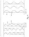
Fig. 1 is a fragmentary elevation view of a column with the column shell taken in vertical section to show structured packing modules of the present invention positioned within the column; -
Fig. 2 is a top plan view of the column taken along line 2-2 ofFig. 1 in the direction of the arrows; -
FIG. 3 is a side elevation view of one of the structured packing modules; and -
FIG. 4 is a fragmentary top plan view showing two embodiments of the corrugated plates which can be used in the structured packing modules. - Turning now to the drawings in greater detail and initially to
Fig. 1 , a column suitable for use in mass transfer and heat exchange processes is represented generally by thenumeral 10.Column 10 includes an upright,external shell 12 that is generally cylindrical in configuration, although other configurations, including polygonal, are possible and are within the scope of the present invention.Shell 12 is of any suitable diameter and height and is constructed from one or more rigid materials that are desirably inert to, or are otherwise compatible with the fluids and conditions present during operation of thecolumn 10. -
Column 10 is of a type used for processing fluid streams, typically liquid and vapor streams, to obtain fractionation products and/or to otherwise cause mass transfer and/or heat exchange between the fluid streams. For example,column 10 can be one in which crude atmospheric, lube vacuum, crude vacuum, fluid or thermal cracking fractionating, coker or visbreaker fractionating, coke scrubbing, reactor off-gas scrubbing, gas quenching, edible oil deodorization, pollution control scrubbing, and other severe service processes occur. - The
shell 12 of thecolumn 10 defines an openinternal region 14 in which the desired mass transfer and/or heat exchange between the fluid streams occurs. Normally, the fluid streams comprise one or more ascending vapor streams and one or more descending liquid streams. Alternatively, the fluid streams may comprise both ascending and descending liquid streams or an ascending gas stream and a descending liquid stream. - The fluid streams are directed to the
column 10 through any number of feed lines (not shown) positioned at appropriate locations along the height of thecolumn 10. One or more vapor streams can also be generated within thecolumn 10 rather than being introduced into thecolumn 10 through the feed lines. Thecolumn 10 will also typically include an overhead line (not shown) for removing a vapor product or byproduct and a bottom stream takeoff line (not shown) for removing a liquid product or byproduct from thecolumn 10. Other column components that are typically present, such as reflux stream lines, reboilers, condensers, vapor horns, liquid distributors, and the like, are not illustrated in the drawings because they are conventional in nature and an illustration of these components is not believed to be necessary for an understanding of the present invention. - In accordance with the present invention, one or
more layers 15a-d of structuredpacking modules 16 are positioned within the openinternal region 14 of thecolumn 10. Turning additionally toFigs. 2-4 , each structuredpacking module 16 comprises a plurality of upright, parallel-extending,corrugated plates 18 constructed from a suitably rigid material, such as any of various metals, plastics, or ceramics, having sufficient strength and thickness to withstand erosion and other conditions experienced within thecolumn 10. - As can best be seen in
Fig. 4 , the corrugations extend along the entire surface of theplates 18 and are generally of a triangular or sinusoidal cross section. The corrugations inadjacent plates 18 of each structuredpacking module 16 extending in a criss-crossing or cross-corrugated fashion. The angle of inclination of the corrugations in relation to the vertical axis of thecolumn 10 can be selected for the requirements of particular applications. For example, inclination angles of 30, 45, and 60 degrees, as well as other angles, may be used. - If the corrugations of
adjacent plates 18 within each structuredpacking module 16 were allowed to contact each other, the points of contact would provide low flow regions where solids are more likely to accumulate and cause fouling or coking. Thus, the corrugations ofadjacent plates 18 within each structuredpacking module 16 are maintained in spaced apart relationship along their entire length byspacer elements 20 which are joined to theplates 18. Thespacer elements 20 are designed to maintain separation between theadjacent plates 18 along their entire length and width to provide unimpeded flow paths for a fluid, typically a liquid, descending along all of the surfaces of the plates and a fluid, typically a vapor, ascending in the open spacing between theplates 18. The corrugations ofadjacent plates 18 form inclined flow channels for this descending vapor. Because the corrugations ofadjacent plates 18 do not contact each other or other structures, the flow of the liquid and vapor along theplates 18 is generally uniform without the presence of low flow regions that could cause the accumulation of solids on theplates 18 and resulting coking or fouling of theplates 18. - The
spacer elements 20 may take any of various suitable forms. In the illustrated embodiment, thespacer elements 20 are a series ofsmooth rods 22 that extend along the top and bottom edges of the structuredpacking modules 16 in a generally perpendicular direction to theplates 18. Therods 22 are secured to theplates 18 by welding or other means. Therods 22 may extend through or may be recessed withinapertures 24 formed in the edges of theplates 18 so that they do not impede contact between the top edges ofplates 18 in one structuredpacking module 16 and the bottom edges ofplates 18 in an overlying structuredpacking module 18. Therods 22 can have a round, triangular, square or other desired cross section. Theapertures 24 receiving therods 22 can be formed as notches or complete holes and likewise can have a round, triangular, square or other desired shape. Thespacer elements 20 function to secure together theplates 18 within each structuredpacking module 16 and to maintain the desired spacing between the corrugations of theadjacent plates 18. It is to be understood that other types ofspacing elements 20 besidesrods 22 may be used to perform these functions. This is contemplated by and within the scope of the present invention. Desirably, however, thespacer elements 20 are constructed and attached to theplates 18 in a manner to reduce the opportunity for solids to accumulate on thespacer elements 20 or at their points of attachment to theplates 18. - The crimp angle Φ (
Fig. 4 ) and the height h2 (Fig. 4 ) or amplitude of the corrugations in eachplate 18, as well as the spacing betweenadjacent plates 18 within each structuredpacking module 16, can be varied for particular applications. As the crimp height of the corrugations increases, the number ofplates 18 that may be positioned within the cross section of thecolumn 10 decreases. Likewise, as the spacing between theplates 18 increases, the number ofplates 18 that may be positioned across the cross-sectional area of thecolumn 10 decreases. In general, as the number, or surface area, of theplates 18 increases, the efficiency of the mass transfer or heat exchange process likewise increases. At the same time, however, the pressure drop between the top and bottom edges of the structuredpacking modules 16 increases and the fluid flow capacity of the structuredpacking modules 16 decreases. - The likelihood that solids will accumulate on the surfaces of the
plates 18 also increases as the bending radius of the corrugation peaks decreases. Thus, in severe service applications where fouling and coking are of concern, it is generally desirable to reduce the bending radius of theplates 18 to reduce the opportunity for solids to accumulate on theplates 18, while at the same time selecting the crimp angle and height of the corrugations and the spacing betweenadjacent plates 18 to provide the desired pressure drop and fluid flow capacity for thestructured packing module 16. - Each
layer 15a-d ofstructured packing modules 16 may consist of a singlestructured packing module 16 that extends completely across the cross section of thecolumn 10 and is supported on a support ring (not shown) fixed to thecolumn shell 12, anunderlying packing module 16, or another suitable support structure. Alternatively, a plurality of individualstructured packing modules 16 in a brick-like form may be assemble to form one or more of thelayers 15a-d. Eachstructured packing modules 16 is normally stacked directly on the adjacent underlying structuredpacking module 16 and is typically rotated so that thecorrugated plates 18 in one layer are positioned in vertical planes that are angled with respect to the vertical planes defined by thecorrugated plates 18 in adjacent layers. This angle of rotation is typically 45 or 90 degrees, but can be other angles if desired. - The entire surfaces of the
plates 18 are generally smooth and free of surface texturing and apertures (other than theapertures 24 used to secure therods 22 to the plates 18) that may allow solids to accumulate on theplates 18. Spray nozzles (not shown) may be positioned above and/or below themodules 16 to direct a spray wash onto the surfaces of theplates 18 to dislodge or prevent the accumulation of solids on theplates 18. In order to allow the spray wash to reach all surfaces of theplates 18, themodules 16 may be constructed with a vertical height of as little as approximately 2 and 7/8th inches. In other applications, thestructured packing modules 16 may have a height of up to or greater than approximately 6 inches. In applications where solids in the fluid feed streams would cause plugging of the spray nozzles or conventional trough-type fluid distributors that feed the fluid to themodules 16, a weir trough-type liquid distributor may be used. - In use, one or more of the structured
packing modules 16 are positioned within the openinternal region 14 within thecolumn 10 for use in facilitating mass transfer and/or heat exchange between fluid streams flowing countercurrently within thecolumn 10. As the fluid streams encounter theplates 18 in the one or morestructured packing modules 16, the fluid streams spread over the surfaces of theplates 18 to increase the area of contact and, thus, the mass transfer and/or heat exchange between the fluid streams. Because the corrugations ofadjacent plates 18 are spaced apart from each other, a fluid stream, typically a liquid stream, is able to descend along the inclined surface of the corrugations in a generally uniform manner without being impeded by low flow zones that typically occur when the corrugations are in contact with each other or other structure elements along their length. Another fluid stream, typically a vapor stream, is likewise able to ascend in the open spacing between theplates 18 in a substantially uniform manner without being impeded by areas of low flow that would result if the corrugations were in contact with each other or other structural elements along their length. In this manner, thestructured packing modules 16 provide the desired structural strength and separation efficiency while being resistant to fouling and coking. - From the foregoing, it will be seen that this invention is one well adapted to attain all the ends and objectives hereinabove set forth together with other advantages that are inherent to the structure.
Claims (13)
- A structured packing module comprising: a plurality of upright, parallel-extending, plates having corrugations, characterised by the plates being arranged with the corrugations of adjacent plates extending in a criss-crossing fashion; and spacer elements which secure the plates in spaced-apart relationship with the corrugations of adjacent plates spaced from and not in contact with each other or other structures along substantially an entire length of the corrugations to form an open spacing between facing surfaces of the plates, wherein said surfaces of the plates and said open spacing between the plates form flow paths for fluids.
- The structured packing module of claim 1, wherein the corrugations extend along an entire surface of each plate.
- A mass transfer or heat exchange column comprising: a shell defining an open internal region; and a structured packing module positioned within said open internal region, said structured packing module comprising: a plurality of upright, parallel-extending, plates having corrugations, characterised by the plates being arranged with the corrugations of adjacent plates extending in a criss-crossing fashion; and spacer elements which secure the plates in spaced-apart relationship with the corrugations of adjacent plates spaced from and not in contact with each other or other structures along substantially an entire length of the corrugations to form an open spacing between facing surfaces of the plates, wherein said surfaces of the plates and said open spacing between the plates form flow paths for fluids.
- The structured packing of claim 1 or column of claim 3, wherein the surfaces of the plates are smooth and generally free of texturing.
- The structured packing of claim 1 or column of claim 3, wherein the spacer elements comprise rods extending through the plates.
- The structured packing of claim 5 or column of claim 5, wherein the plates have a top and a bottom edge and said rods extend through said top and bottom edges.
- The structured packing of claim 6 or column of claim 6, wherein said plates have apertures at said top and bottom edges and said rods extend through said apertures.
- The structured packing of claim 7 or the column of claim 7, wherein said surfaces of the plates are free of apertures except at said top and bottom edges.
- The structured packing of claim 8 or the column of claim 8, wherein said rods are smooth and of round cross section.
- The structured packing of claim 8 or column of claim 8, wherein said rods are welded to said plates.
- A process for causing mass transfer and/or heat exchange between fluid streams flowing within a mass transfer column having structured packing modules of claim 1 positioned with an open internal region formed a shell of the column, said process comprising the step of passing said fluid streams through said structured packing modules along said flow paths to cause said mass transfer and/or heat exchange on said surfaces of said plates.
- The process of claim 11, including the step of causing substantially uniform flow of said fluid streams along said flow paths.
- The process of claim 11, wherein said step of passing said fluid streams through said structured packing modules comprising passing a descending liquid stream and an ascending vapor stream through said structured packing modules.
Applications Claiming Priority (3)
| Application Number | Priority Date | Filing Date | Title |
|---|---|---|---|
| US9775808P | 2008-09-17 | 2008-09-17 | |
| US12/560,837 US8298412B2 (en) | 2008-09-17 | 2009-09-16 | Structured packing module for mass transfer column and process involving same |
| PCT/US2009/057234 WO2010033653A2 (en) | 2008-09-17 | 2009-09-17 | Structured packing module for mass transfer column and process involving same |
Publications (3)
| Publication Number | Publication Date |
|---|---|
| EP2331255A2 EP2331255A2 (en) | 2011-06-15 |
| EP2331255A4 EP2331255A4 (en) | 2015-04-15 |
| EP2331255B1 true EP2331255B1 (en) | 2018-12-26 |
Family
ID=42006284
Family Applications (1)
| Application Number | Title | Priority Date | Filing Date |
|---|---|---|---|
| EP09815160.8A Active EP2331255B1 (en) | 2008-09-17 | 2009-09-17 | Structured packing module for mass transfer column and process involving same |
Country Status (13)
| Country | Link |
|---|---|
| US (2) | US8298412B2 (en) |
| EP (1) | EP2331255B1 (en) |
| JP (1) | JP5635511B2 (en) |
| KR (1) | KR101631332B1 (en) |
| CN (1) | CN102149461B (en) |
| BR (1) | BRPI0918622B1 (en) |
| CA (1) | CA2736883C (en) |
| ES (1) | ES2713951T3 (en) |
| MX (1) | MX2011002321A (en) |
| PL (1) | PL223659B1 (en) |
| RU (1) | RU2500468C2 (en) |
| TW (1) | TWI577916B (en) |
| WO (1) | WO2010033653A2 (en) |
Families Citing this family (10)
| Publication number | Priority date | Publication date | Assignee | Title |
|---|---|---|---|---|
| US8298412B2 (en) * | 2008-09-17 | 2012-10-30 | Koch-Glitsch, Lp | Structured packing module for mass transfer column and process involving same |
| US20160061541A1 (en) * | 2014-08-26 | 2016-03-03 | Guang X. Chen | Contacting device and method |
| RU2697299C2 (en) * | 2014-12-23 | 2019-08-13 | Эвапко, Инк. | Bidirectional filler for use in cooling towers |
| EP3132848B1 (en) | 2015-08-20 | 2020-01-08 | Sulzer Management AG | Structured packing with specific mounting clips |
| USD863788S1 (en) * | 2017-04-04 | 2019-10-22 | Alstom Transport Technologies | Textile |
| US11014064B2 (en) * | 2017-05-02 | 2021-05-25 | Koch-Glitsch, Lp | Structured packing module for mass transfer columns |
| US10953382B2 (en) * | 2017-06-09 | 2021-03-23 | Koch-Glitsch, Lp | Structured packing module for mass transfer columns |
| RU2020124208A (en) * | 2018-01-08 | 2022-02-10 | Кох-Глич, Лп | STRUCTURED PACKED MODULE FOR USE IN MASS TRANSFER COLUMN AND METHOD OF ITS ASSEMBLY |
| CN108870427A (en) * | 2018-09-10 | 2018-11-23 | 甘肃红峰机械有限责任公司 | A kind of fume waste heat recyclable device |
| US11774189B2 (en) * | 2020-09-29 | 2023-10-03 | Air Products And Chemicals, Inc. | Heat exchanger, hardway fin arrangement for a heat exchanger, and methods relating to same |
Family Cites Families (50)
| Publication number | Priority date | Publication date | Assignee | Title |
|---|---|---|---|---|
| US2321110A (en) * | 1936-08-25 | 1943-06-08 | Servel Inc | Heat exchanger |
| US2793017A (en) * | 1954-10-04 | 1957-05-21 | Dow Chemical Co | Apparatus for distributing falling liquid in thin films |
| GB806975A (en) * | 1955-10-27 | 1959-01-07 | Atomic Energy Authority Uk | Improvements in distillation columns |
| US3466019A (en) * | 1967-08-04 | 1969-09-09 | Ronald Priestley | Gas-liquid contact packing sheets |
| US3568461A (en) * | 1967-11-22 | 1971-03-09 | Mc Donnell Douglas Corp | Fractionation apparatus |
| SE328597B (en) * | 1968-04-04 | 1970-09-21 | C Munters | |
| US3540702A (en) * | 1968-08-22 | 1970-11-17 | Nippon Kokan Kk | Multi-wave packing material and a device for utilizing the same |
| DE2208577A1 (en) * | 1971-03-12 | 1972-09-28 | Trustul De Constructii Ind Clu | Infill link for water cooling towers |
| US3733063A (en) * | 1971-09-24 | 1973-05-15 | Marley Co | Chevron ribbed fill unit for water cooling tower |
| SE385971B (en) * | 1973-12-20 | 1976-07-26 | Svenska Flaektfabriken Ab | CONTACT BODY FOR WATER AND AIR, MAINLY INTENDED FOR COOLING TOWER AND HUMIDIFIER |
| US3965225A (en) * | 1974-03-11 | 1976-06-22 | Baltimore Aircoil Company, Inc. | Spacer-turbulator |
| SE7509633L (en) * | 1975-02-07 | 1976-08-09 | Terence Peter Nicholson | DEVICE FOR FLAT HEAT EXCHANGER |
| JPS5212658U (en) * | 1975-07-16 | 1977-01-28 | ||
| US4361426A (en) * | 1981-01-22 | 1982-11-30 | Baltimore Aircoil Company, Inc. | Angularly grooved corrugated fill for water cooling tower |
| US4597916A (en) * | 1983-06-21 | 1986-07-01 | Glitsch, Inc. | Method of and apparatus for intermediate lamella vapor liquid contact |
| SE459826B (en) * | 1984-10-03 | 1989-08-07 | Munters Ab Carl | INSERT BODY OF FOLDED LAYERS WITH SPECIFICALLY DESIGNED EDGE PARTIES |
| US4676934A (en) * | 1985-09-27 | 1987-06-30 | Jaeger Products, Inc. | Structured WV packing elements |
| US4668443A (en) * | 1985-11-25 | 1987-05-26 | Brentwood Industries, Inc. | Contact bodies |
| SU1560304A1 (en) * | 1987-05-05 | 1990-04-30 | Винницкий политехнический институт | Regulator packing |
| US5063000A (en) * | 1989-05-03 | 1991-11-05 | Mix Thomas W | Packing elements |
| FR2649192A1 (en) * | 1989-06-30 | 1991-01-04 | Inst Francais Du Petrole | METHOD AND DEVICE FOR SIMULTANEOUS TRANSFER OF MATERIAL AND HEAT |
| US5073236A (en) * | 1989-11-13 | 1991-12-17 | Gelbein Abraham P | Process and structure for effecting catalytic reactions in distillation structure |
| US5124087A (en) * | 1990-10-04 | 1992-06-23 | Evapco International, Inc. | Gas and liquid contact body |
| US5217788A (en) * | 1992-05-11 | 1993-06-08 | Brentwood Industries | Corrugated sheet assembly |
| ES2123759T3 (en) * | 1992-12-01 | 1999-01-16 | Sulzer Chemtech Ag | LINING TRIM FOR EXCHANGER COLUMN. |
| US5438836A (en) * | 1994-08-05 | 1995-08-08 | Praxair Technology, Inc. | Downflow plate and fin heat exchanger for cryogenic rectification |
| US5523062A (en) * | 1994-11-03 | 1996-06-04 | Chemical Research & Licening Company | Catalytic distillation distribution structure |
| GB9515492D0 (en) * | 1995-07-28 | 1995-09-27 | Aitken William H | Apparatus for combined heat and mass transfer |
| US5624733A (en) * | 1995-06-27 | 1997-04-29 | The Boc Group, Inc. | Structured packing |
| CN1090055C (en) * | 1995-07-08 | 2002-09-04 | 巴斯福股份公司 | Cloth or cloth-like packing which is subject to low pressure losses and has ordered structure for use in material-exchange columns and rectification method using such packing |
| GB9522086D0 (en) | 1995-10-31 | 1996-01-03 | Ici Plc | Fluid-fluid contacting apparatus |
| US5700403A (en) * | 1996-01-24 | 1997-12-23 | Praxair Technology, Inc. | Distillation column employing structured packing which reduces wall flow |
| US6286818B1 (en) * | 1997-07-04 | 2001-09-11 | Kuhni Ag | Internal members for mass transfer columns |
| US6293528B1 (en) * | 1998-04-23 | 2001-09-25 | Uop Llc | Fractionation apparatus with low surface area grid above tray deck |
| US6000685A (en) * | 1998-06-29 | 1999-12-14 | Catalytic Distillation Technologies | Gas/liquid contact structure |
| US6101841A (en) * | 1998-10-02 | 2000-08-15 | Praxair Technology, Inc. | Cryogenic rectification system with high strength and high capacity packing |
| US6206350B1 (en) * | 1998-11-25 | 2001-03-27 | Baltimore Aircoil Company, Inc. | Film fill-pack for inducement of spiraling gas flow in heat and mass transfer contact apparatus with self spacing fill-sheets |
| CA2257128A1 (en) * | 1998-12-23 | 2000-06-23 | Alberta Research Council | Structured packing assembly |
| US6325360B1 (en) * | 1998-12-23 | 2001-12-04 | Alberta Research Council Inc. | Structured packing assembly |
| US6357728B1 (en) * | 1999-03-15 | 2002-03-19 | Air Products And Chemicals, Inc. | Optimal corrugated structured packing |
| US6280819B1 (en) * | 1999-06-25 | 2001-08-28 | The Boc Group, Inc. | Structured packing |
| US6517058B1 (en) * | 2000-03-02 | 2003-02-11 | Sandkuhl Clay Works, Inc. | Fill packs for use in heat and mass transfer devices |
| US6378332B1 (en) * | 2000-09-07 | 2002-04-30 | Praxair Technology, Inc. | Packing with low contacting crimp pattern |
| US6857469B2 (en) * | 2000-12-18 | 2005-02-22 | Thermasys Corporation | Fin-tube block type heat exchanger with grooved spacer bars |
| EP1667792A1 (en) * | 2003-09-17 | 2006-06-14 | Tadayoshi Nagaoka | Reactor with packing mean |
| US7125004B2 (en) | 2003-12-15 | 2006-10-24 | Koch-Glitsch, Lp | Liquid distributor for use in mass transfer column |
| JP2005342602A (en) * | 2004-06-02 | 2005-12-15 | Nichias Corp | Corrugated plate laminated body filter |
| CN2728609Y (en) * | 2004-09-26 | 2005-09-28 | 山东莱芜欣琦新材料科技有限公司 | Ceramic corrogation plate within ceramic plate |
| UA22966U (en) * | 2007-03-06 | 2007-04-25 | Kin Borys Solomonovych El | Structured cap for heat-mass exchange apparatuses |
| US8298412B2 (en) * | 2008-09-17 | 2012-10-30 | Koch-Glitsch, Lp | Structured packing module for mass transfer column and process involving same |
-
2009
- 2009-09-16 US US12/560,837 patent/US8298412B2/en active Active
- 2009-09-17 KR KR1020117001216A patent/KR101631332B1/en active IP Right Grant
- 2009-09-17 WO PCT/US2009/057234 patent/WO2010033653A2/en active Application Filing
- 2009-09-17 EP EP09815160.8A patent/EP2331255B1/en active Active
- 2009-09-17 TW TW098131339A patent/TWI577916B/en active
- 2009-09-17 PL PL394029A patent/PL223659B1/en unknown
- 2009-09-17 RU RU2011115095/05A patent/RU2500468C2/en active
- 2009-09-17 CA CA2736883A patent/CA2736883C/en active Active
- 2009-09-17 BR BRPI0918622-0A patent/BRPI0918622B1/en active IP Right Grant
- 2009-09-17 JP JP2011527071A patent/JP5635511B2/en active Active
- 2009-09-17 CN CN200980136153.6A patent/CN102149461B/en active Active
- 2009-09-17 ES ES09815160T patent/ES2713951T3/en active Active
- 2009-09-17 MX MX2011002321A patent/MX2011002321A/en active IP Right Grant
-
2012
- 2012-10-24 US US13/658,901 patent/US8540878B2/en active Active
Non-Patent Citations (1)
| Title |
|---|
| None * |
Also Published As
| Publication number | Publication date |
|---|---|
| PL223659B1 (en) | 2016-10-31 |
| US8540878B2 (en) | 2013-09-24 |
| CA2736883A1 (en) | 2010-03-25 |
| TWI577916B (en) | 2017-04-11 |
| CA2736883C (en) | 2016-12-06 |
| EP2331255A4 (en) | 2015-04-15 |
| CN102149461B (en) | 2014-08-13 |
| KR101631332B1 (en) | 2016-06-24 |
| PL394029A1 (en) | 2011-07-18 |
| KR20110069761A (en) | 2011-06-23 |
| WO2010033653A3 (en) | 2010-06-10 |
| US20100065501A1 (en) | 2010-03-18 |
| BRPI0918622A2 (en) | 2016-05-17 |
| RU2500468C2 (en) | 2013-12-10 |
| CN102149461A (en) | 2011-08-10 |
| EP2331255A2 (en) | 2011-06-15 |
| JP5635511B2 (en) | 2014-12-03 |
| MX2011002321A (en) | 2011-05-10 |
| US8298412B2 (en) | 2012-10-30 |
| BRPI0918622B1 (en) | 2017-12-19 |
| ES2713951T3 (en) | 2019-05-24 |
| JP2012506763A (en) | 2012-03-22 |
| RU2011115095A (en) | 2012-10-27 |
| US20130043010A1 (en) | 2013-02-21 |
| TW201013089A (en) | 2010-04-01 |
| WO2010033653A2 (en) | 2010-03-25 |
Similar Documents
| Publication | Publication Date | Title |
|---|---|---|
| EP2331255B1 (en) | Structured packing module for mass transfer column and process involving same | |
| US9757662B2 (en) | Heat integrated distillation column using structured packing | |
| US20210069668A1 (en) | Structured packing module for use in a mass transfer column and method of assembly | |
| US10953382B2 (en) | Structured packing module for mass transfer columns | |
| CA3232487A1 (en) | Support beam for supporting internals within a mass transfer column | |
| US20190193047A1 (en) | Structured packing with enhanced fluid-flow interface | |
| CA3049746C (en) | Contact tray having baffle wall for concentrating low liquid flow and method involving same | |
| EP3562569B1 (en) | Contact tray having picketed liquid flow barriers and method involving same | |
| US20090101546A1 (en) | Distillation tower construction and operation | |
| WO1999003553A1 (en) | Tray-to-tray transfer device for chemical process tower |
Legal Events
| Date | Code | Title | Description |
|---|---|---|---|
| PUAI | Public reference made under article 153(3) epc to a published international application that has entered the european phase |
Free format text: ORIGINAL CODE: 0009012 |
|
| 17P | Request for examination filed |
Effective date: 20110405 |
|
| AK | Designated contracting states |
Kind code of ref document: A2 Designated state(s): AT BE BG CH CY CZ DE DK EE ES FI FR GB GR HR HU IE IS IT LI LT LU LV MC MK MT NL NO PL PT RO SE SI SK SM TR |
|
| AX | Request for extension of the european patent |
Extension state: AL BA RS |
|
| DAX | Request for extension of the european patent (deleted) | ||
| A4 | Supplementary search report drawn up and despatched |
Effective date: 20150317 |
|
| RIC1 | Information provided on ipc code assigned before grant |
Ipc: B01D 3/00 20060101ALI20150311BHEP Ipc: B01D 15/00 20060101ALI20150311BHEP Ipc: B01J 19/32 20060101AFI20150311BHEP |
|
| GRAP | Despatch of communication of intention to grant a patent |
Free format text: ORIGINAL CODE: EPIDOSNIGR1 |
|
| STAA | Information on the status of an ep patent application or granted ep patent |
Free format text: STATUS: GRANT OF PATENT IS INTENDED |
|
| INTG | Intention to grant announced |
Effective date: 20180824 |
|
| GRAS | Grant fee paid |
Free format text: ORIGINAL CODE: EPIDOSNIGR3 |
|
| GRAA | (expected) grant |
Free format text: ORIGINAL CODE: 0009210 |
|
| STAA | Information on the status of an ep patent application or granted ep patent |
Free format text: STATUS: THE PATENT HAS BEEN GRANTED |
|
| AK | Designated contracting states |
Kind code of ref document: B1 Designated state(s): AT BE BG CH CY CZ DE DK EE ES FI FR GB GR HR HU IE IS IT LI LT LU LV MC MK MT NL NO PL PT RO SE SI SK SM TR |
|
| REG | Reference to a national code |
Ref country code: GB Ref legal event code: FG4D |
|
| REG | Reference to a national code |
Ref country code: CH Ref legal event code: EP |
|
| REG | Reference to a national code |
Ref country code: DE Ref legal event code: R096 Ref document number: 602009056433 Country of ref document: DE |
|
| REG | Reference to a national code |
Ref country code: AT Ref legal event code: REF Ref document number: 1080656 Country of ref document: AT Kind code of ref document: T Effective date: 20190115 |
|
| REG | Reference to a national code |
Ref country code: IE Ref legal event code: FG4D |
|
| REG | Reference to a national code |
Ref country code: NL Ref legal event code: FP |
|
| PG25 | Lapsed in a contracting state [announced via postgrant information from national office to epo] |
Ref country code: LT Free format text: LAPSE BECAUSE OF FAILURE TO SUBMIT A TRANSLATION OF THE DESCRIPTION OR TO PAY THE FEE WITHIN THE PRESCRIBED TIME-LIMIT Effective date: 20181226 Ref country code: NO Free format text: LAPSE BECAUSE OF FAILURE TO SUBMIT A TRANSLATION OF THE DESCRIPTION OR TO PAY THE FEE WITHIN THE PRESCRIBED TIME-LIMIT Effective date: 20190326 Ref country code: BG Free format text: LAPSE BECAUSE OF FAILURE TO SUBMIT A TRANSLATION OF THE DESCRIPTION OR TO PAY THE FEE WITHIN THE PRESCRIBED TIME-LIMIT Effective date: 20190326 Ref country code: FI Free format text: LAPSE BECAUSE OF FAILURE TO SUBMIT A TRANSLATION OF THE DESCRIPTION OR TO PAY THE FEE WITHIN THE PRESCRIBED TIME-LIMIT Effective date: 20181226 Ref country code: LV Free format text: LAPSE BECAUSE OF FAILURE TO SUBMIT A TRANSLATION OF THE DESCRIPTION OR TO PAY THE FEE WITHIN THE PRESCRIBED TIME-LIMIT Effective date: 20181226 Ref country code: HR Free format text: LAPSE BECAUSE OF FAILURE TO SUBMIT A TRANSLATION OF THE DESCRIPTION OR TO PAY THE FEE WITHIN THE PRESCRIBED TIME-LIMIT Effective date: 20181226 |
|
| REG | Reference to a national code |
Ref country code: LT Ref legal event code: MG4D |
|
| REG | Reference to a national code |
Ref country code: ES Ref legal event code: FG2A Ref document number: 2713951 Country of ref document: ES Kind code of ref document: T3 Effective date: 20190524 |
|
| PG25 | Lapsed in a contracting state [announced via postgrant information from national office to epo] |
Ref country code: SE Free format text: LAPSE BECAUSE OF FAILURE TO SUBMIT A TRANSLATION OF THE DESCRIPTION OR TO PAY THE FEE WITHIN THE PRESCRIBED TIME-LIMIT Effective date: 20181226 Ref country code: GR Free format text: LAPSE BECAUSE OF FAILURE TO SUBMIT A TRANSLATION OF THE DESCRIPTION OR TO PAY THE FEE WITHIN THE PRESCRIBED TIME-LIMIT Effective date: 20190327 |
|
| REG | Reference to a national code |
Ref country code: AT Ref legal event code: MK05 Ref document number: 1080656 Country of ref document: AT Kind code of ref document: T Effective date: 20181226 |
|
| PG25 | Lapsed in a contracting state [announced via postgrant information from national office to epo] |
Ref country code: PT Free format text: LAPSE BECAUSE OF FAILURE TO SUBMIT A TRANSLATION OF THE DESCRIPTION OR TO PAY THE FEE WITHIN THE PRESCRIBED TIME-LIMIT Effective date: 20190426 Ref country code: CZ Free format text: LAPSE BECAUSE OF FAILURE TO SUBMIT A TRANSLATION OF THE DESCRIPTION OR TO PAY THE FEE WITHIN THE PRESCRIBED TIME-LIMIT Effective date: 20181226 Ref country code: PL Free format text: LAPSE BECAUSE OF FAILURE TO SUBMIT A TRANSLATION OF THE DESCRIPTION OR TO PAY THE FEE WITHIN THE PRESCRIBED TIME-LIMIT Effective date: 20181226 |
|
| PG25 | Lapsed in a contracting state [announced via postgrant information from national office to epo] |
Ref country code: SM Free format text: LAPSE BECAUSE OF FAILURE TO SUBMIT A TRANSLATION OF THE DESCRIPTION OR TO PAY THE FEE WITHIN THE PRESCRIBED TIME-LIMIT Effective date: 20181226 Ref country code: RO Free format text: LAPSE BECAUSE OF FAILURE TO SUBMIT A TRANSLATION OF THE DESCRIPTION OR TO PAY THE FEE WITHIN THE PRESCRIBED TIME-LIMIT Effective date: 20181226 Ref country code: EE Free format text: LAPSE BECAUSE OF FAILURE TO SUBMIT A TRANSLATION OF THE DESCRIPTION OR TO PAY THE FEE WITHIN THE PRESCRIBED TIME-LIMIT Effective date: 20181226 Ref country code: IS Free format text: LAPSE BECAUSE OF FAILURE TO SUBMIT A TRANSLATION OF THE DESCRIPTION OR TO PAY THE FEE WITHIN THE PRESCRIBED TIME-LIMIT Effective date: 20190426 Ref country code: SK Free format text: LAPSE BECAUSE OF FAILURE TO SUBMIT A TRANSLATION OF THE DESCRIPTION OR TO PAY THE FEE WITHIN THE PRESCRIBED TIME-LIMIT Effective date: 20181226 |
|
| REG | Reference to a national code |
Ref country code: DE Ref legal event code: R097 Ref document number: 602009056433 Country of ref document: DE |
|
| PG25 | Lapsed in a contracting state [announced via postgrant information from national office to epo] |
Ref country code: DK Free format text: LAPSE BECAUSE OF FAILURE TO SUBMIT A TRANSLATION OF THE DESCRIPTION OR TO PAY THE FEE WITHIN THE PRESCRIBED TIME-LIMIT Effective date: 20181226 Ref country code: AT Free format text: LAPSE BECAUSE OF FAILURE TO SUBMIT A TRANSLATION OF THE DESCRIPTION OR TO PAY THE FEE WITHIN THE PRESCRIBED TIME-LIMIT Effective date: 20181226 |
|
| PLBE | No opposition filed within time limit |
Free format text: ORIGINAL CODE: 0009261 |
|
| STAA | Information on the status of an ep patent application or granted ep patent |
Free format text: STATUS: NO OPPOSITION FILED WITHIN TIME LIMIT |
|
| 26N | No opposition filed |
Effective date: 20190927 |
|
| PG25 | Lapsed in a contracting state [announced via postgrant information from national office to epo] |
Ref country code: SI Free format text: LAPSE BECAUSE OF FAILURE TO SUBMIT A TRANSLATION OF THE DESCRIPTION OR TO PAY THE FEE WITHIN THE PRESCRIBED TIME-LIMIT Effective date: 20181226 |
|
| PG25 | Lapsed in a contracting state [announced via postgrant information from national office to epo] |
Ref country code: TR Free format text: LAPSE BECAUSE OF FAILURE TO SUBMIT A TRANSLATION OF THE DESCRIPTION OR TO PAY THE FEE WITHIN THE PRESCRIBED TIME-LIMIT Effective date: 20181226 |
|
| PG25 | Lapsed in a contracting state [announced via postgrant information from national office to epo] |
Ref country code: MC Free format text: LAPSE BECAUSE OF FAILURE TO SUBMIT A TRANSLATION OF THE DESCRIPTION OR TO PAY THE FEE WITHIN THE PRESCRIBED TIME-LIMIT Effective date: 20181226 |
|
| REG | Reference to a national code |
Ref country code: CH Ref legal event code: PL |
|
| PG25 | Lapsed in a contracting state [announced via postgrant information from national office to epo] |
Ref country code: CH Free format text: LAPSE BECAUSE OF NON-PAYMENT OF DUE FEES Effective date: 20190930 Ref country code: IE Free format text: LAPSE BECAUSE OF NON-PAYMENT OF DUE FEES Effective date: 20190917 Ref country code: LI Free format text: LAPSE BECAUSE OF NON-PAYMENT OF DUE FEES Effective date: 20190930 Ref country code: LU Free format text: LAPSE BECAUSE OF NON-PAYMENT OF DUE FEES Effective date: 20190917 |
|
| PG25 | Lapsed in a contracting state [announced via postgrant information from national office to epo] |
Ref country code: CY Free format text: LAPSE BECAUSE OF FAILURE TO SUBMIT A TRANSLATION OF THE DESCRIPTION OR TO PAY THE FEE WITHIN THE PRESCRIBED TIME-LIMIT Effective date: 20181226 |
|
| PG25 | Lapsed in a contracting state [announced via postgrant information from national office to epo] |
Ref country code: HU Free format text: LAPSE BECAUSE OF FAILURE TO SUBMIT A TRANSLATION OF THE DESCRIPTION OR TO PAY THE FEE WITHIN THE PRESCRIBED TIME-LIMIT; INVALID AB INITIO Effective date: 20090917 Ref country code: MT Free format text: LAPSE BECAUSE OF FAILURE TO SUBMIT A TRANSLATION OF THE DESCRIPTION OR TO PAY THE FEE WITHIN THE PRESCRIBED TIME-LIMIT Effective date: 20181226 |
|
| PG25 | Lapsed in a contracting state [announced via postgrant information from national office to epo] |
Ref country code: MK Free format text: LAPSE BECAUSE OF FAILURE TO SUBMIT A TRANSLATION OF THE DESCRIPTION OR TO PAY THE FEE WITHIN THE PRESCRIBED TIME-LIMIT Effective date: 20181226 |
|
| PGFP | Annual fee paid to national office [announced via postgrant information from national office to epo] |
Ref country code: NL Payment date: 20230816 Year of fee payment: 15 |
|
| PGFP | Annual fee paid to national office [announced via postgrant information from national office to epo] |
Ref country code: IT Payment date: 20230810 Year of fee payment: 15 Ref country code: GB Payment date: 20230727 Year of fee payment: 15 |
|
| PGFP | Annual fee paid to national office [announced via postgrant information from national office to epo] |
Ref country code: FR Payment date: 20230710 Year of fee payment: 15 Ref country code: DE Payment date: 20230726 Year of fee payment: 15 Ref country code: BE Payment date: 20230818 Year of fee payment: 15 |
|
| PGFP | Annual fee paid to national office [announced via postgrant information from national office to epo] |
Ref country code: ES Payment date: 20231004 Year of fee payment: 15 |