EP2330039A1 - Dämpfungselement für ein Treibstoffzufuhr-Leitungssystem eines Raumfahrtantriebssystems - Google Patents
Dämpfungselement für ein Treibstoffzufuhr-Leitungssystem eines Raumfahrtantriebssystems Download PDFInfo
- Publication number
- EP2330039A1 EP2330039A1 EP10015187A EP10015187A EP2330039A1 EP 2330039 A1 EP2330039 A1 EP 2330039A1 EP 10015187 A EP10015187 A EP 10015187A EP 10015187 A EP10015187 A EP 10015187A EP 2330039 A1 EP2330039 A1 EP 2330039A1
- Authority
- EP
- European Patent Office
- Prior art keywords
- damping element
- elastic body
- fuel
- fuel supply
- element according
- Prior art date
- Legal status (The legal status is an assumption and is not a legal conclusion. Google has not performed a legal analysis and makes no representation as to the accuracy of the status listed.)
- Granted
Links
Images



Classifications
-
- B—PERFORMING OPERATIONS; TRANSPORTING
- B64—AIRCRAFT; AVIATION; COSMONAUTICS
- B64G—COSMONAUTICS; VEHICLES OR EQUIPMENT THEREFOR
- B64G1/00—Cosmonautic vehicles
- B64G1/22—Parts of, or equipment specially adapted for fitting in or to, cosmonautic vehicles
- B64G1/40—Arrangements or adaptations of propulsion systems
- B64G1/402—Propellant tanks; Feeding propellants
-
- F—MECHANICAL ENGINEERING; LIGHTING; HEATING; WEAPONS; BLASTING
- F02—COMBUSTION ENGINES; HOT-GAS OR COMBUSTION-PRODUCT ENGINE PLANTS
- F02K—JET-PROPULSION PLANTS
- F02K9/00—Rocket-engine plants, i.e. plants carrying both fuel and oxidant therefor; Control thereof
- F02K9/42—Rocket-engine plants, i.e. plants carrying both fuel and oxidant therefor; Control thereof using liquid or gaseous propellants
-
- F—MECHANICAL ENGINEERING; LIGHTING; HEATING; WEAPONS; BLASTING
- F16—ENGINEERING ELEMENTS AND UNITS; GENERAL MEASURES FOR PRODUCING AND MAINTAINING EFFECTIVE FUNCTIONING OF MACHINES OR INSTALLATIONS; THERMAL INSULATION IN GENERAL
- F16L—PIPES; JOINTS OR FITTINGS FOR PIPES; SUPPORTS FOR PIPES, CABLES OR PROTECTIVE TUBING; MEANS FOR THERMAL INSULATION IN GENERAL
- F16L55/00—Devices or appurtenances for use in, or in connection with, pipes or pipe systems
- F16L55/04—Devices damping pulsations or vibrations in fluids
- F16L55/045—Devices damping pulsations or vibrations in fluids specially adapted to prevent or minimise the effects of water hammer
- F16L55/05—Buffers therefor
- F16L55/052—Pneumatic reservoirs
- F16L55/053—Pneumatic reservoirs the gas in the reservoir being separated from the fluid in the pipe
Definitions
- the invention relates to a damping element for a fuel supply pipe system of a space propulsion system.
- the invention further relates to a space propulsion system comprising an engine coupled to a fuel tank via a fuel supply conduit system.
- a spacecraft is placed on a launcher in orbit.
- a space propulsion system of the spacecraft is inactive during takeoff on the launch vehicle.
- measures are taken to ensure that fuel present on board the spacecraft is provided only in a fuel tank, but not in a fuel supply line system connecting the fuel tank to an engine.
- the lines of the fuel supply pipe system with shut-off.
- the adjoining pipe is filled with a gas.
- the gas is released through opening valves of the fuel supply piping system. This process is called “venting”. After the outlet of the gas there is a vacuum in the pipes. With a subsequent opening of the shut-off valves, the lines of the fuel supply line system fill with fuel in a very short time.
- the opening of the shut-off devices is referred to as "priming".
- a damping element for a fuel supply pipe system of a space propulsion system is proposed.
- This includes a housing having a receiving space coupled to a conduit of the fuel supply conduit system which connects a fuel tank to an engine.
- the damping element further comprises an elastic body arranged in the receiving space, which upon opening of a Tankabsperrorgans the fuel supply piping system by the influx of fuel into the fuel supply piping system as defined impact is deformable, whereby the shock is damped.
- the impact produced by the sudden filling with fuel in the fuel supply line system can be reduced in its effect to such an extent that the pressure load neither damages the engine nor can physical effects in the fuel be triggered, which can lead to detonation , Due to its simple structure, this is reliable in its function. It can also be manufactured with low weight and cost.
- the simple construction of the damping element also ensures that no dirt is produced, e.g. by the abrasion of moving parts.
- a spring is arranged in the interior of the elastic body, with which the yielding volume and the spring stiffness of the damping element are adjustable.
- the yielding volume and the spring stiffness of the system of elastic body spring can be adjusted arbitrarily. There is no link between the geometry of the elastic body and its spring stiffness.
- the receiving space opens at a first end face to the line with a predetermined cross-sectional area, wherein the cross-sectional area forms a contact surface of the elastic body, with which the elastic body comes into mechanical contact with the fuel after opening the Tankabsperrorgans.
- the cross-sectional area is such that, optionally in conjunction with the spring, the force acting on the cross-sectional area is proportioned to the volume inside the elastic body and / or the stiffness of the elastic body so as to dampen the surge of fuel.
- the size of the contact line can be determined by a cross-sectional opening or the cross section of a supply line to the fuel supply line system. Due to the cross-sectional area, the material of the elastic body, its mechanical properties and the geometric shape are then set the damping properties of the damping element. These can thus be set defined in the design of the damping element and its integration in the space propulsion system.
- the elastic body has one or more recesses through which during the deformation of the elastic body fuel enters the interior of the elastic body, wherein the receiving space of the damping element is completely filled with fuel after the end of the shock.
- the damping element does not contribute to vibrations in the fuel supply pipe system.
- the damping element can thereby behave rigidly.
- the damping element during the subsequent operating phase of the space propulsion system is inactive. Vibrations excited by the engine are not amplified in the fuel supply piping system.
- the recess or recesses are arranged in the region of the cross-sectional area. It is particularly preferred if the recess or recesses are arranged in the region of a hole area of the cross-sectional area, wherein the hole area is (substantially) smaller than the cross-sectional area of the elastic body. Due to the small area compared to the cross-sectional area of the hole area remains a large contact surface of the elastic body with the fuel. As a result, the deformation rate of the elastic body can be kept low. This also results in a smaller speed of the fuel inlet into the interior of the elastic body.
- the cross-sectional size of the recess or recesses for filling the interior of the elastic body is independent of the damping characteristics are.
- the duration of the filling process can be set independently of the duration of the shock and thus the damping.
- the elastic body has the shape of a bellows, in particular a bellows.
- a load is only by the pressure generated from outside the bellows.
- the bellows design also allows deformation to dampen the impact regardless of the hole area or the number and / or size of the recesses.
- a dense spring system regardless of the hole surface is used, as is the case with a bellows.
- a further advantage of the design as a bellows is that stresses occur at maximum in the elastic region during its deformation. On the other hand, plastic deformation can be avoided, thereby providing increased reliability.
- the elastic body is made of a metal, in particular titanium.
- the housing has the shape of a cylinder with a height H, wherein in the cylinder at a second end face a cup-shaped projection of the depth T projects, which surrounds the elastic body. Due to the size and dimensions of the cup-shaped projection, the volume can be set inside the housing. In addition, the projection can be used for simplified attachment and guidance of the elastic body or the spring. Conveniently, the ratio of H / T is about 2.
- the elastic body has an outer diameter d_a and an inner diameter d_i, where: d_a / d_i ⁇ 1.5. This ratio is determined by the concrete shape of the bellows. For the function of the invention, a deviating relationship can be chosen.
- the damping element is designed according to a further specific embodiment such that the fuel surge can be reduced by this to a maximum pressure of 70 bar, preferably of 50 bar.
- Such a damping element is particularly suitable for use in a hydrazine engine.
- the invention further proposes a space propulsion system including an engine coupled to a fuel tank via a fuel supply conduit system.
- a damper of the type described above is provided in the fuel supply piping system.
- the space propulsion system has the same advantages as described above in connection with the damping element.
- the engine can be designed, for example, as a hydrazine drive.
- the fuel supply piping system includes an engine valve disposed proximate the engine, wherein the damping element is disposed as a terminal element of the fuel supply piping system immediately in front of the engine valve.
- the damping element is located in front of the engine valve.
- Fig. 1 shows a schematic representation of an inventive damping element 10 for a fuel supply piping system 21 of a space propulsion system.
- the spacecraft propulsion system includes an engine coupled to a fuel tank via the fuel supply conduit system 21.
- the fuel tank is shut off by a Tankabsperrorgan which is part of the fuel supply line system.
- the fuel supply piping system 21 further includes an engine valve, not shown in detail, which is disposed near the engine.
- the damping element 10 is preferably arranged as a final element of the fuel supply line system 21 immediately before the engine valve. Since the basic structure of such a space propulsion system is well known to those skilled in the art, a more detailed description is omitted here.
- the damping element 10 comprises a cylindrical housing 12, the receiving space 22 of which is coupled via a feed line 20 to a line 19 of the fuel supply line system 21.
- the receiving space 22 designed as a bellows elastic body 12 is arranged. This deforms when opening a not shown in the figure Tankabsperrorgans the fuel supply line system 21 by the resulting by the influx of fuel into the lines 19, 20 shock (so-called. Priming or fuel or pressure surge) in a defined manner. Due to the resilient properties of the bellows, the shock is damped.
- the pressure surge can be reduced to about 50 bar using a damping element according to the invention. This ensures that neither parts of the fuel supply line system suffer damage or physical effects are triggered in the fuel, which lead to a detonation. In contrast, a pressure load of 250 bar is above a limit of a hydrazine drive.
- the cylindrical housing 11 is coupled with its first end face 16 to the supply line 20.
- the housing 11 At its second end face 17 of the housing, the housing 11 has a cup-shaped projection 14 which projects into the interior of the housing and reduces its volume.
- a base 15 of the projection serves as an optional inside of the bellows 12 provided spring 13 as an abutment. The other end of the spring 13 is supported in the region of the cross-sectional area 18 on the bellows 12 itself.
- the cup-shaped projection 14 which projects into the interior of the housing 11, there is a guide for the bellows 12. In particular, its elastic deformation ensures that it does not deform into the interior of the housing.
- the cup-shaped projection 14 has a diameter which corresponds approximately to an inner diameter d_i of the bellows 12.
- the cup-shaped projection 14 protrudes with a depth T into the interior of the housing 11.
- the housing 11 has a height H, wherein the ratio of H / T is about 2.
- the cross-sectional area 18 is dimensioned such that the force acting on it (caused by the pressure of the fuel) in relation to the volume inside the bellows 12 and / or the rigidity of the bellows 12, optionally in conjunction with the inside of the bellows 12th provided spring 13, is dimensioned such that the fuel surge is damped.
- recesses are introduced into the bellows through which fuel can flow into the interior of the bellows.
- the bellows is suitably made as a metal bellows made of titanium to ensure compatibility with aerospace fuels. In principle, other materials can also be used.
- Its outer diameter d_a is for example about 28 mm.
- the inner diameter d_i is about 18 mm.
- the number of layers is for example 3, the wave number, for example 12.
- the height of the bellows 12, which corresponds approximately to the height H of the housing 11, is about 38 mm. This results in an effective cross-sectional area 18 of 4 cm 2 , and, at a pressure of 50 bar, a travel of 10 mm.
- Fig. 1 Furthermore, a cross section along the line DD is shown, which illustrates the cylindrical shape of the housing 11.
- the venting process described initially is carried out first.
- the receiving space 22 of the damping element 10 is evacuated in addition to the entire fuel supply line system.
- the elastic bellows 12 dampens the resulting pressure surge. Due to the elasticity of the damping element of the shock is drawn in time, whereby the amplitude of the shock is reduced.
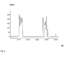
- Fig. 2 shows the time course of a pressure surge without the presence of in Fig. 1 described damping element.
- the pressure is applied over time. As can readily be seen, occurs after 10 ms, a fuel surge at over 250 bar, which oscillates for about 2 ms until a pressure reduction to almost 0 takes place. Another pressure surge is recognizable after approx. 23 ms.
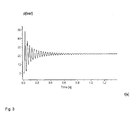
- FIG. 3 shows Fig. 3 the time course of the pressure when using a damping element according to the invention.
- the FIGS. 4 and 5 illustrate in a schematic way in addition the deflection of the damping element or the speed of movement of the damper.
- FIGS. 3 to 5 are not shown to scale to each other, it is readily apparent that a pressure curve corresponding to the course of the deflection and the speed of movement of the damping element is present.
- the damping function is easily recognizable due to the exponentially decaying pressure curve.
- the damping element according to the invention has the advantage that the parameters described below can be selected independently of each other. This makes it possible to realize an adaptation of the damping element to any situation or space propulsion systems.
Landscapes
- Engineering & Computer Science (AREA)
- Chemical & Material Sciences (AREA)
- Combustion & Propulsion (AREA)
- General Engineering & Computer Science (AREA)
- Remote Sensing (AREA)
- Aviation & Aerospace Engineering (AREA)
- Mechanical Engineering (AREA)
- Pipe Accessories (AREA)
Abstract
Description
- Die Erfindung betrifft ein Dämpfungselement für ein Treibstoffzufuhr-Leitungssystem eines Raumfahrtantriebssystems. Die Erfindung betrifft ferner ein Raumfahrtantriebssystem, das ein Triebwerk umfasst, das über ein Treibstoffzufuhr-Leitungssystem mit einem Treibstofftank gekoppelt ist.
- Typischerweise wird ein Raumfahrzeug auf einer Trägerrakete in den Orbit gebracht. Aus Sicherheitsgründen ist ein Raumfahrtantriebssystem des Raumfahrzeugs während des Starts auf der Trägerrakete inaktiv. Insbesondere sind Maßnahmen getroffen, dass an Bord des Raumfahrzeugs befindlicher Treibstoff lediglich in einem Treibstofftank, nicht jedoch in einem, den Treibstofftank mit einem Triebwerk verbindenden, Treibstoffzufuhr-Leitungssystem vorgesehen ist. Zu diesem Zweck sind - an der Auslaßseite des Treibstofftanks die Leitungen des Treibstoffzufuhr-Leitungssystems mit Absperrorganen versperrt. Die daran anschließende Leitung ist mit einem Gas gefüllt. Zur Inbetriebnahme des Raumfahrtantriebssystems wird das Gas durch sich öffnende Ventile des Treibstoffzufuhr-Leitungssystems entlassen. Dieser Vorgang wird als "Venting" bezeichnet. Nach dem Auslass des Gases herrscht ein Vakuum in den Leitungen. Bei einer nun folgenden Öffnung der Absperrorgane füllen sich die Leitungen des Treibstoffzufuhr-Leitungssystems in sehr kurzer Zeit mit Treibstoff. Das Öffnen der Absperrorgane wird als "Priming" bezeichnet.
- Das schnelle Füllen der Leitungen führt zu einem sog. "Priming Schock". Dies ist ein hoher, kurzzeitiger dynamischer Druckanstieg in dem Treibstoffzuführ-Leitungssystem. Je nach Ausgestaltung des Raumfahrtantriebssystems kann dieser Druckstoß Werte erreichen, die das Antriebssystem entweder mechanisch durch die hohe Druckbelastung schädigen oder physikalische Effekte im Treibstoff auslösen, die zu einer Detonation und damit Zerstörung des Raumfahrzeugs führen. Übermäßige Druckspitzen sind deshalb in jedem Falle zu vermeiden.
- Hierzu ist es bekannt, den Primingprozess, d.h. das Füllen der Leitungen des Treibstoffzufuhr-Leitungssystems mit Treibstoff, zu verlangsamen. Hierzu ist ein weiteres Ventil notwendig, das einen mit einer Blende versehenen und parallel zur Haupttreibstoffleitung angeordneten Leitungsast freischaltet. Nachteilig hieran ist, dass für den verlangsamten Füllvorgang der Leitungen eine gewisse Zeit benötigt wird, die jedoch nicht bei allen Arten von Raumfahrtantriebssystemen zur Verfügung steht. Beispielsweise ist die für einen verlangsamten Primingprozess notwendige Zeit bei Landesystemen für Sonden nicht akzeptabel. Ein weiterer Nachteil besteht darin, dass ein zusätzliches, aktiv zu betätigendes Ventil notwendig ist, welches einerseits Kosten und andererseits Gewicht verursacht.
- Es ist deshalb Aufgabe der vorliegenden Erfindung, ein System zur passiven Dämpfung eines durch das schnelle Füllen eines Treibstoffzufuhr-Leitungssystems verursachten Treibstoffstoßes anzugeben.
- Diese Aufgabe wird gelöst durch ein Dämpfungselement gemäß den Merkmalen des Patentanspruchs 1 sowie ein Raumfahrtantriebssystem gemäß den Merkmalen des Patentanspruchs 13. Vorteilhafte Ausgestaltungen ergeben sich jeweils aus den abhängigen Patentansprüchen.
- Es wird ein Dämpfungselement für ein Treibstoffzufuhr-Leitungssystem eines Raumfahrtantriebssystems vorgeschlagen. Dieses umfasst ein Gehäuse mit einem Aufnahmeraum, der mit einer Leitung des Treibstoffzufuhr-Leitungssystems gekoppelt ist, welcher einen Treibstofftank mit einem Triebwerk verbindet. Das Dämpfungselement umfasst ferner einen in dem Aufnahmeraum angeordneten elastischen Körper, der beim Öffnen eines Tankabsperrorgans des Treibstoffzufuhr-Leitungssystems durch den durch das Einströmen von Treibstoff in das Treibstoffzufuhr-Leitungssystem entstehenden Stoß definiert verformbar ist, wodurch der Stoß gedämpft wird.
- Durch das erfindungsgemäße Dämpfungselement kann der in dem Treibstoffzufuhr-Leitungssystem durch das schlagartige Füllen mit Treibstoff entstehende Stoß in seiner Wirkung auf ein solches Maß reduziert werden, dass die Druckbelastung weder das Triebwerk schädigt noch physikalische Effekte im Treibstoff auslösbar sind, welche zu einer Detonation führen können. Aufgrund seines einfachen Aufbaus ist dieses in seiner Funktion verlässlich. Es kann darüber hinaus mit geringem Gewicht und kostengünstig hergestellt werden. Der einfache konstruktive Aufbau des Dämpfungselements sorgt darüber hinaus dafür, dass kein Schmutz produziert wird, z.B. durch den Abrieb sich bewegender Teile.
- Optional ist eine Feder im Inneren des elastischen Körpers angeordnet, mit welcher das nachgebende Volumen und die Federsteifigkeit des Dämpfungselements einstellbar sind. Durch die Unterstützung der zusätzlichen Feder lassen sich das nachgebende Volumen und die Federsteifigkeit des Systems elastischer Körper-Feder beliebig einstellen. Dabei besteht keine Verknüpfung zwischen der Geometrie des elastischen Körpers und seiner Federsteifigkeit.
- Es ist weiterhin zweckmäßig, wenn der Aufnahmeraum an einer ersten Stirnseite an die Leitung mit einer vorgegebenen Querschnittsfläche mündet, wobei die Querschnittsfläche eine Kontaktfläche des elastischen Körpers ausbildet, mit welcher der elastische Körper mit dem Treibstoff nach dem Öffnen des Tankabsperrorgans in mechanischen Kontakt gelangt. Insbesondere ist die Querschnittsfläche derart bemessen, dass, optional in Verbindung mit der Feder, die auf die Querschnittsfläche wirkende Kraft im Verhältnis zu dem Volumen im Inneren des elastischen Körpers und/oder der Steifigkeit des elastischen Körpers derart bemessen ist, dass der Treibstoffstoß gedämpft wird. Die Größe der Kontaktleitung kann dabei durch eine Querschnittsöffnung oder den Querschnitt einer Zuleitung zu dem Treibstoffzufuhr-Leitungssystem festgelegt werden. Durch die Querschnittsfläche, das Material des elastischen Körpers, dessen mechanische Eigenschaften sowie die geometrische Gestalt werden dann die Dämpfungseigenschaften des Dämpfungselements festgelegt. Diese können somit bei der Konstruktion des Dämpfungselements sowie dessen Integration in das Raumfahrtantriebssystem definiert eingestellt werden.
- Zweckmäßigerweise weist der elastische Körper eine oder mehrere Aussparungen auf, durch die während der Verformung des elastischen Körpers Treibstoff in das Innere des elastischen Körpers gelangt, wobei der Aufnahmeraum des Dämpfungselements nach dem Ende des Stoßes vollständig mit Treibstoff gefüllt ist. Hierdurch kann sichergestellt werden, dass bei später gefüllten Leitungen des Treibstoffzufuhr-Leitungssystems und dem Betrieb des Raumfahrtantriebssystems das Dämpfungselement nicht zu Schwingungen in dem Treibstoffzufuhr-Leitungssystem beiträgt. Das Dämpfungselement kann sich hierdurch starr verhalten. Hierdurch ist das Dämpfungselement während der anschließenden Betriebsphase des Raumfahrtantriebssystems inaktiv. Durch das Triebwerk angeregte Schwingungen werden im Treibstoffzufuhr-Leitungssystem damit nicht verstärkt.
- Zweckmäßigerweise sind die Aussparung oder Aussparungen im Bereich der Querschnittsfläche angeordnet. Besonders bevorzugt ist es, wenn die Aussparung oder Aussparungen im Bereich einer Lochfläche der Querschnittsfläche angeordnet sind, wobei die Lochfläche (wesentlich) kleiner als die Querschnittsfläche des elastischen Körpers ist. Durch die im Vergleich zur Querschnittsfläche kleine Lochfläche verbleibt eine große Kontaktfläche des elastischen Körpers mit dem Treibstoff. Hierdurch kann die Verformungsgeschwindigkeit des elastischen Körpers gering gehalten werden. Hierdurch ergibt sich auch eine kleinere Geschwindigkeit des Treibstoff-Zulaufs ins Innere des elastischen Körpers.
- Bei der Dimensionierung und Anordnung der Aussparung oder Aussparungen ist sicherzustellen, dass die Querschnittsgröße der Aussparung oder Aussparungen zum Füllen des Inneren des elastischen Körpers unabhängig von den Dämpfungseigenschaften sind. Auf diese Weise lässt sich die Dauer des Füllvorgangs unabhängig von der Zeitdauer des Stoßes und damit der Dämpfung einstellen.
- Es ist weiterhin zweckmäßig, wenn der elastische Körper die Gestalt eines Balgs, insbesondere eines Faltenbalgs, aufweist. Bei einer Ausgestaltung des elastischen Körpers als Faltenbalg erfolgt eine Belastung nur durch den, von außerhalb des Faltenbalgs erzeugten Druck. Das Faltenbalg-Design ermöglicht darüber hinaus die Verformung zum Dämpfen des Stoßes unabhängig von der Lochfläche bzw. der Anzahl und/oder Größe der Aussparungen. Bevorzugt kommt ein dichtes Federsystem, unabhängig von der Lochfläche zum Einsatz, wie dies bei einem Faltenbalg der Fall ist. Ein weiterer Vorteil der Ausgestaltung als Balg besteht darin, dass bei dessen Verformung Spannungen maximal im elastischen Bereich auftreten. Eine plastische Verformung kann hingegen vermieden werden, wodurch eine erhöhte Zuverlässigkeit bereitgestellt ist.
- Gemäß einer weiteren Ausgestaltung ist der elastische Körper aus einem Metall, insbesondere Titan, gebildet.
- In einer konkreten Ausgestaltung weist das Gehäuse die Gestalt eines Zylinders mit einer Höhe H auf, wobei in dem Zylinder an einer zweiten Stirnseite ein topfförmiger Vorsprung der Tiefe T ragt, der den elastischen Körper umschließt. Durch die Größe und Abmaße des topfförmigen Vorsprungs kann das Volumen im Inneren des Gehäuses festgelegt werden. Darüber hinaus kann der Vorsprung zur vereinfachten Befestigung und Führung des elastischen Körpers bzw. der Feder dienen. Zweckmäßigerweise ist das Verhältnis von H/T ungefähr 2.
- In einer weiteren konkreten Ausgestaltung weist der elastische Körper einen äußeren Durchmesser d_a und einen inneren Durchmesser d_i auf, wobei gilt: d_a/d_i ≈ 1,5. Dieses Verhältnis ist durch die konkrete Form des Faltenbalgs bestimmt. Für die Funktion der Erfindung kann auch ein davon abweichendes Verhältnis gewählt werden.
- Das Dämpfungselement ist gemäß einer weiteren konkreten Ausgestaltung derart ausgestaltet, dass der Treibstoffstoß durch dieses auf einen Maximaldruck von 70 bar, bevorzugt von 50 bar, reduzierbar ist. Ein solches Dämpfungselement eignet sich insbesondere zur Verwendung in einem Hydrazin-Triebwerk.
- Die Erfindung schlägt ferner ein Raumfahrtantriebssystem vor, das ein Triebwerk umfasst, das über ein Treibstoffzufuhr-Leitungssystem mit einem Treibstofftank gekoppelt ist. In dem Treibstoffzufuhr-Leitungssystem ist ein Dämpfungselement der vorstehend beschriebenen Art vorgesehen. Das Raumfahrtantriebssystem weist dabei die gleichen Vorteile auf, wie diese vorstehend in Verbindung mit dem Dämpfungselement beschrieben wurden. Das Triebwerk kann beispielsweise als Hydrazinantrieb ausgebildet sein.
- Zweckmäßigerweise umfasst das Treibstoffzufuhr-Leitungssystem ein Triebwerksventil, das nahe dem Triebwerk angeordnet ist, wobei das Dämpfungselement als abschließendes Element des Treibstoffzufuhr-Leitungssystems unmittelbar vor dem Triebwerksventil angeordnet ist. Hierdurch kann der Treibstoffstoß unmittelbar an seinem Entstehungsort, d.h. dem Leitungsende (vom Treibstofftank her gesehen) gedämpft werden. Um die Beschädigung des Triebwerksventils zu vermeiden, ist das Dämpfungselement vor dem Triebwerksventil angeordnet.
- Die Erfindung wird nachfolgend näher anhand eines Ausführungsbeispiels erläutert. Es zeigen:
- Fig. 1
- eine schematische Darstellung eines erfindungsgemäßen Dämpfungselements für ein Treibstoffzufuhr-Leitungssystem eines Raumfahrtantriebssystems,
- Fig. 2
- den zeitlichen Verlauf eines Druckstoßes in einem Treibstoffzufuhr-Leitungssystem ohne ein erfindungsgemäßes Dämpfungselement,
- Fig. 3
- den zeitlichen Verlauf eines Druckstoßes in einem Treibstoffzufuhr-Leitungssystem bei Verwendung eines erfindungsgemäßen Dämpfungselements,
- Fig.
- 4 den zeitlichen Verlauf der Auslenkung eines elastischen Körpers des Dämpfungselements bei einem Treibstoffstoß, und
- Fig. 5 den
- zeitlichen Verlauf der Bewegungsgeschwindigkeit des elastischen Körpers des Dämpfungselements.
-
Fig. 1 zeigt in schematischer Darstellung ein erfindungsgemäßes Dämpfungselement 10 für ein Treibstoffzufuhr-Leitungssystem 21 eines Raumfahrtantriebssystems. Das nicht näher dargestellte Raumfahrtantriebssystem umfasst ein Triebwerk, das über das Treibstoffzufuhr-Leitungssystem 21 mit einem Treibstofftank gekoppelt ist. Der Treibstofftank ist durch ein Tankabsperrorgan absperrbar, welches Teil des Treibstoffzufuhr-Leitungssystems ist. Das Treibstoffzufuhr-Leitungssystem 21 umfasst ferner ein nicht näher dargestelltes Triebwerksventil, das nahe dem Triebwerk angeordnet ist. Das Dämpfungselement 10 ist vorzugsweise als abschließendes Element des Treibstoffzufuhr-Leitungssystems 21 unmittelbar vor dem Triebwerksventil angeordnet. Da der prinzipielle Aufbau eines derartigen Raumfahrtantriebssystems dem Fachmann hinlänglich bekannt ist, wird auf eine eingehendere Beschreibung an dieser Stelle verzichtet. - Das erfindungsgemäße Dämpfungselement 10 umfasst ein zylinderförmiges Gehäuse 12, dessen Aufnahmeraum 22, der über eine Zuleitung 20 mit einer Leitung 19 des Treibstoffzufuhr-Leitungssystems 21 gekoppelt ist. In dem Aufnahmeraum 22 ist ein als Faltenbalg ausgebildeter elastischer Körper 12 angeordnet. Dieser verformt sich beim Öffnen eines in der Figur nicht näher dargestellten Tankabsperrorgans des Treibstoffzufuhr-Leitungssystems 21 durch den durch das Einströmen von Treibstoff in die Leitungen 19, 20 entstehenden Stoß (sog. Priming bzw. Treibstoff- oder Druckstoß) in definierter Weise. Durch die federnden Eigenschaften des Faltenbalgs wird der Stoß gedämpft.
- Während bei einem Raumfahrtantriebssystem der durch das eingangs beschriebene Priming entstehende Stoß ca. 250 bar beträgt, kann unter Einsatz eines erfindungsgemäßen Dämpfungselements der Druckstoß auf ca. 50 bar reduziert werden. Hierdurch ist sichergestellt, dass weder Teile des Treibstoffzufuhr-Leitungssystems Schaden erleiden oder physikalische Effekte in dem Treibstoff ausgelöst werden, welche zu einer Detonation führen. Demgegenüber ist eine Druckbelastung von 250 bar oberhalb eines Limits eines Hydrazinantriebs.
- Das zylinderförmige Gehäuse 11 ist mit seiner ersten Stirnseite 16 mit der Zuleitung 20 gekoppelt. Der Durchmesser des Gehäuses 11, der in etwa einem Außendurchmesser d_a des Faltenbalgs entspricht, ist dabei größer als der Durchmesser der Zuleitung 20, wodurch der an die erste Stirnseite 16 ragende Faltenbalg 12 dem durch die Zuleitung 20 einströmenden Treibstoff lediglich im Bereich einer Querschnittsfläche 18 ausgesetzt ist. An seiner zweiten Stirnseite 17 des Gehäuses weist das Gehäuse 11 einen topfförmigen Vorsprung 14 auf, der in das Innere des Gehäuses ragt und dessen Volumen verkleinert. Eine Grundfläche 15 des Vorsprungs dient einer optional im Inneren des Faltenbalgs 12 vorgesehenen Feder 13 als Widerlager. Das andere Ende der Feder 13 stützt sich im Bereich der Querschnittsfläche 18 an dem Faltenbalg 12 selbst ab. Durch den topfförmigen Vorsprung 14, der ins Innere des Gehäuses 11 ragt, ergibt sich eine Führung für den Faltenbalg 12. Insbesondere wird bei dessen elastischer Verformung sichergestellt, dass sich dieser nicht ins Innere des Gehäuses hinein verformt. Der topfförmige Vorsprung 14 weist einen Durchmesser auf, der in etwa einem inneren Durchmesser d_i des Faltenbalgs 12 entspricht. Der topfförmige Vorsprung 14 ragt mit einer Tiefe T in das Innere des Gehäuses 11 hinein. Das Gehäuse 11 weist eine Höhe H auf, wobei das Verhältnis von H/T ungefähr 2 beträgt.
- Die Querschnittsfläche 18 ist derart bemessen, dass die auf sie wirkende Kraft (verursacht durch den Druck des Treibstoffs) im Verhältnis zu dem Volumen im Inneren des Faltenbalgs 12 und/oder der Steifigkeit des Faltenbalgs 12, optional in Verbindung mit der im Inneren des Faltenbalgs 12 vorgesehenen Feder 13, derart bemessen ist, dass der Treibstoffstoß gedämpft wird. Im Bereich der Querschnittsfläche 18 sind Aussparungen in den Faltenbalg eingebracht, durch die Treibstoff ins Innere des Faltenbalgs strömen kann.
- Der Faltenbalg wird zweckmäßigerweise als Metallbalg aus Titan hergestellt um Kompatibilität mit raumfahrtüblichen Treibstoffen zu gewährleisten. Prinzipiell können auch andere Werkstoffe zum Einsatz kommen. Dessen äußerer Durchmesser d_a beträgt z.B. ca. 28 mm. Der innere Durchmesser d_i beträgt ca. 18 mm. Die Lagenzahl beträgt z.B. 3, die Wellenzahl z.B. 12. Die Höhe des Faltenbalgs 12, die in etwa der Höhe H des Gehäuses 11 entspricht, beträgt ca. 38 mm. Hieraus ergibt sich eine effektive Querschnittfläche 18 von 4 cm2, und, bei einem Druck von 50 bar, ein Federweg von 10 mm.
- In
Fig. 1 ist ferner ein Querschnitt längs der Linie D-D dargestellt, welche die zylinderförmige Gestalt des Gehäuses 11 illustriert. - Bei Inbetriebnahme des Raumfahrtantriebssystems wird zunächst der eingangs beschriebene Venting-Prozess durchgeführt. Dabei wird neben dem gesamten Treibstoffzufuhr-Leitungssystem auch der Aufnahmeraum 22 des Dämpfungselements 10 evakuiert. Bei der Initialisierung des Primings kommt es zu einem Druckanstieg am Leitungsende der Leitung 19, an dem das Dämpfungselement 10 angeordnet ist. Der elastische Faltenbalg 12 dämpft den dabei entstehenden Druckstoß ab. Durch die Elastizität des Dämpfungselements wird der Stoß zeitlich in die Länge gezogen, wodurch die Amplitude des Stoßes reduziert wird.
- Während des Dämpfungsvorgangs fließt durch die im Bereich der Querschnittsfläche 18 vorgesehenen Aussparungen Treibstoff in das Innere des Faltenbalgs 10 bzw. des Aufnahmeraums 22 des Gehäuses 11. Die in der Figur nicht dargestellten Aussparungen sind derart dimensioniert, dass der Auffüllvorgang des Inneren des Faltenbalgs deutlich länger als der durch den Treibstoff verursachte Stoß andauert. Hierdurch wird die Elastizität des Dämpfungselements während des Primings nicht eingeschränkt. Nach Beendigung der durch den Treibstoff verursachten Schwingungen im Treibstoffzufuhr-Leitungssystem 21 ist der Aufnahmeraum 22 des Dämpfungselements 10 voll gefüllt. Durch den im Inneren des Faltenbalgs 10 "eingesperrten" Treibstoff, der nur sehr langsam durch die Aussparungen entweichen kann, ist das Dämpfungselement nahezu inaktiv, da der Treibstoff nur sehr gering komprimierbar ist.
-
Fig. 2 zeigt den zeitlichen Verlauf eines Druckstoßes ohne das Vorhandensein des inFig. 1 beschriebenen Dämpfungselements. Dabei ist der Druck über die Zeit aufgetragen. Wie ohne Weiteres zu erkennen ist, tritt nach 10 ms ein Treibstoffstoß mit über 250 bar auf, welcher für ca. 2 ms ausschwingt, bis eine Druckreduktion auf nahezu 0 erfolgt. Ein weiterer Druckstoß ist nach ca. 23 ms erkennbar. - Demgegenüber zeigt
Fig. 3 den zeitlichen Verlauf des Drucks bei Einsatz eines erfindungsgemäßen Dämpfungselements. DieFiguren 4 und5 illustrieren in schematischer Weise zusätzlich die Auslenkung des Dämpfungselements bzw. die Bewegungsgeschwindigkeit des Dämpfers. Obwohl dieFiguren 3 bis 5 nicht maßstabsgetreu zueinander dargestellt sind, ist ohne Weiteres erkennbar, dass ein dem Druckverlauf entsprechender Verlauf der Auslenkung sowie der Bewegungsgeschwindigkeit des Dämpfungselements vorliegt. Durch den Einsatz des Dämpfungselements kann der Druckstoß bei ansonsten gleicher Konfiguration des Raumfahrtantriebssystems auf weniger als 50 bar begrenzt werden. Die Dämpfungsfunktion ist aufgrund des exponentiell abklingenden Druckverlaufs ohne Weiteres erkennbar. - Das erfindungsgemäße Dämpfungselement weist den Vorteil auf, dass die nachfolgend beschriebenen Parameter unabhängig voneinander gewählt werden können. Hierdurch lässt sich eine Anpassung des Dämpfungselements auf beliebige Einsatzsituationen bzw. Raumfahrtantriebssysteme realisieren.
- Als Auslegungsparameter werden berücksichtigt:
- Die Form des elastischen Körpers 12, der in
Fig. 1 lediglich beispielhaft als Faltenbalg ausgebildet ist, darf bei seiner Verformung Spannungen maximal im elastischen Bereich aufweisen. Eine plastische Verformung muss vermieden werden. - Durch die Unterstützung einer zusätzlichen Feder lassen sich das nachgebende Volumen und die Federsteifigkeit des Systems elastischer Körper und Feder beliebig einstellen. Es besteht keine Verknüpfung zwischen der Geometrie des elastischen Körpers und seiner Federsteifigkeit.
- Die Steifigkeit der Feder wird zusammen mit der Querschnittsfläche 18 derart gewählt, dass das nachgebende Volumen ausreichend groß ist, um den Stoß zu dämpfen.
- Die Verformung des elastischen Körpers durch das Abfedern des Stoßes muss unabhängig von einer im Bereich der Querschnittsfläche vorgesehenen Lochfläche sein. Die Lochfläche ist dabei diejenige Fläche, in deren Bereich die Mehrzahl an Aussparungen im Bereich der Querschnittsfläche angeordnet ist. Bevorzugt kommt ein dichtes Federsystem, unabhängig von der Lochfläche, zum Einsatz, was durch das in
Fig. 1 gezeigte Faltenbalg-Design sichergestellt ist. - Unabhängige Querschnittsgrößen der Löcher zum Füllen des Aufnahmeraums bzw. Inneren des elastischen Körpers 12. Hierdurch lässt sich die Dauer des Füllvorgangs unabhängig von der Stoßdauer einstellen.
- Damit die Verformungsgeschwindigkeit des elastischen Körpers gering bleibt, muss eine große Querschnittsfläche (d.h. Kontaktfläche mit dem Treibstoff) vorgesehen sein, während die Lochfläche klein ist. Damit lassen sich auch geringe Geschwindigkeiten des Treibstoffs im Zulauf realisieren.
- Bei dem in
Fig. 1 dargestellten Faltenbalg-Design erfolgt eine Belastung lediglich durch einen Außendruck. - An dieser Stelle wird angemerkt, dass sich eine Anwendung als Akkumulator oder "hydraulischer Dämpfer" zum Dämpfen von dynamischen Schwingungen während des Betriebs (sog. Wasserhammerstöße) mit dem vorgeschlagenen Dämpfungselement nicht realisieren lassen. Durch das beschriebene Design wird gerade bezweckt, dass sich das Dämpfungselement nach dem Priming starr verhält, während Wasserhammerstöße durch das Treibstoffzufuhr-Leitungssystem gehen, wie diese beispielsweise beim Pulsbetrieb von Triebwerken auftreten. Bei dem erfindungsgemäßen Dämpfungselement werden deshalb nach der Inbetriebnahme die Federeigenschaften verändert. Realisiert wird dies über die Mehrzahl an Aussparungen im Bereich der ersten Stirnfläche des elastischen Körpers, wodurch das durch den elastischen Körper eingeschlossene Volumen langsam mit Treibstoff gefüllt und so die Federeigenschaft blockiert wird.
-
- 10
- Dämpfungselement
- 11
- Gehäuse
- 12
- elastischer Körper
- 13
- Feder
- 14
- topfförmiger Vorsprung
- 15
- Grundfläche des Vorsprungs
- 16
- erste Stirnseite des Gehäuses
- 17
- zweite Stirnseite des Gehäuses
- 18
- Querschnittsfläche
- 19
- Leitung
- 20
- Zuleitung
- 21
- Treibstoffzufuhr-Leitungssystem
- 22
- Aufnahmeraum
- H
- Höhe
- T
- Tiefe
- d_a
- Außendurchmesser
- d_i
- Innendurchmesser
Claims (15)
- Dämpfungselement (10) für ein Treibstoffzufuhr-Leitungssystem (21) eines Raumfahrtantriebssystems, umfassend:- ein Gehäuse (11) mit einem Aufnahmeraum (22), der mit einer Leitung (19) des Treibstoffzufuhr-Leitungssystems (21) gekoppelt ist, welche einen Treibstofftank mit einem Triebwerk verbindet; und- einen in dem Aufnahmeraum (22) angeordneten elastischen Körper (12), der beim Öffnen eines Tankabsperrorgans des Treibstoffzufuhr-Leitungssystems (21) durch den durch das Einströmen von Treibstoff in das Treibstoffzufuhr-Leitungssystem (21) entstehenden Stoß definiert verformbar ist, wodurch der Stoß gedämpft wird.
- Dämpfungselements nach Anspruch 1, bei dem eine Feder im Inneren des elastischen Körpers (12) angeordnet ist, mit welcher das nachgebende Volumen und die Federsteifigkeit des Dämpfungselements (10) einstellbar ist.
- Dämpfungselements nach Anspruch 1 oder 2, bei dem der Aufnahmeraum (22) an einer ersten Stirnseite an die Leitung (19) mit einer vorgegebenen Querschnittsfläche (18) mündet, wobei die Querschnittsfläche (18) eine Kontaktfläche des elastischen Körpers (12) ausbildet, mit welcher der elastische Körper (12) mit dem Treibstoff nach dem Öffnen des Tankabsperrorgans in mechanischen Kontakt gelangt.
- Dämpfungselements nach Anspruch 3, bei dem die Querschnittsfläche (21) derart bemessen ist, dass die auf die Querschnittsfläche (18) wirkende Kraft im Verhältnis zu dem Volumen im Inneren des elastischen Körpers (12) und/oder der Steifigkeit des elastischen Körpers (12) derart bemessen ist, dass der Treibstoffstoß gedämpft wird.
- Dämpfungselements nach einem der vorhergehenden Ansprüche, bei dem der elastische Körper (12) eine oder mehrere Aussparungen aufweist, durch die während der Verformung des elastischen Körpers (12) Treibstoff in das Innere des elastischen Körpers (12) gelangt, wobei der Aufnahmeraum (22) des Dämpfungselements (10) nach dem Ende des Stoßes vollständig mit Treibstoff gefüllt ist.
- Dämpfungselements nach Anspruch 3 und 4 oder 3, 4 und 5, bei dem die Aussparung oder Aussparungen im Bereich der Querschnittsfläche (21) angeordnet sind.
- Dämpfungselements nach Anspruch 3 und 4 oder 3, 4 und 5, bei dem die Aussparung oder Aussparungen im Bereich einer Lochfläche der Querschnittsfläche (18) angeordnet sind, wobei die Lochfläche (wesentlich) kleiner als die Querschnittsfläche (21) des elastischen Körpers (12) ist.
- Dämpfungselements nach einem der vorhergehenden Ansprüche, bei dem der elastische Körper (12) die Gestalt eines Balgs, insbesondere eines Faltenbalgs, aufweist.
- Dämpfungselements nach einem der vorhergehenden Ansprüche, bei dem der elastische Körper (12) aus einem Metall, insbesondere Titan, gebildet ist.
- Dämpfungselements nach einem der vorhergehenden Ansprüche, bei dem das Gehäuse (11) die Gestalt eines Zylinders mit einer Höhe H aufweist, wobei in den Zylinder an einer zweiten Stirnseite ein topfförmiger Vorsprung (14) der Tiefe T ragt, der den elastischen Körper (12) umschließt.
- Dämpfungselements nach einem der vorhergehenden Ansprüche, bei dem der elastische Körper (12) einen äußeren Durchmesser d_a und einen inneren Durchmesser d_i aufweist, wobei gilt: d_a/d_i ≈ 1,5.
- Dämpfungselements nach einem der vorhergehenden Ansprüche, bei dem dieses derart ausgestaltet ist, dass der Stoß durch dieses auf einen Maximaldruck von 70 bar, bevorzugt von 50 bar, reduzierbar ist.
- Raumfahrtantriebssystem, umfassend ein Triebwerk, das über ein Treibstoffzufuhr-Leitungssystem (21) mit einem Treibstofftank gekoppelt ist, wobei in dem Treibstoffzufuhr-Leitungssystem (21) ein Dämpfungselement (10) gemäß einem der vorhergehenden Ansprüche vorgesehen ist.
- Raumfahrtantriebssystem nach Anspruch 13, bei dem das Triebwerk ein Hydrazinantrieb ist.
- Raumfahrtantriebssystem nach Anspruch 13 oder 14, bei dem das Treibstoffzufuhr-Leitungssystem (21) ein Triebwerksventil umfasst, das nahe dem Triebwerk angeordnet ist, wobei das Dämpfungselement (10) als abschließendes Element des Treibstoffzufuhr-Leitungssystem (21) unmittelbar vor dem Triebwerksventil angeordnet ist.
Applications Claiming Priority (1)
| Application Number | Priority Date | Filing Date | Title |
|---|---|---|---|
| DE102009056956.1A DE102009056956B4 (de) | 2009-12-07 | 2009-12-07 | Dämpfungselement für ein Treibstoffzufuhr-Leitungssystem eines Raumfahrtantriebssystems |
Publications (2)
| Publication Number | Publication Date |
|---|---|
| EP2330039A1 true EP2330039A1 (de) | 2011-06-08 |
| EP2330039B1 EP2330039B1 (de) | 2016-08-10 |
Family
ID=43733291
Family Applications (1)
| Application Number | Title | Priority Date | Filing Date |
|---|---|---|---|
| EP10015187.7A Not-in-force EP2330039B1 (de) | 2009-12-07 | 2010-12-01 | Dämpfungselement für ein Treibstoffzufuhr-Leitungssystem eines Raumfahrtantriebssystems |
Country Status (2)
| Country | Link |
|---|---|
| EP (1) | EP2330039B1 (de) |
| DE (1) | DE102009056956B4 (de) |
Citations (6)
| Publication number | Priority date | Publication date | Assignee | Title |
|---|---|---|---|---|
| US3075558A (en) * | 1959-09-24 | 1963-01-29 | Forell Kenneth J Von | Diaphragm type accumulator having means to prevent the diaphragm from folding and crimping on itself due to changes in pressure |
| US5880356A (en) * | 1995-02-20 | 1999-03-09 | Centre National D'etudes Spatiales | Device for pressurizing a unified two-liquid propulsion subsystem geostationary satellites |
| EP1323928A1 (de) * | 2001-12-04 | 2003-07-02 | NHK Spring Co., Ltd. | Druckspeicher mit Sicherheitsventil |
| FR2871441A1 (fr) * | 2004-06-10 | 2005-12-16 | Eads Astrium Sas Soc Par Actio | Procedes de detection de la vidange complete d'un reservoir d'ergol et de gestion d'ergol a bord d'un satellite |
| DE102006025552A1 (de) * | 2006-06-01 | 2007-12-13 | Hydac Technology Gmbh | Hydropneumatischer Druckspeicher |
| EP1918626A1 (de) * | 2006-10-24 | 2008-05-07 | Carl Freudenberg KG | Speicher zur Dämpfung von Druckpulsationen |
Family Cites Families (1)
| Publication number | Priority date | Publication date | Assignee | Title |
|---|---|---|---|---|
| DE3632988A1 (de) | 1986-09-04 | 1988-06-30 | Schubert Werner | Sonde zur minderung von druckstosswirkungen im inneren eines hohlkoerpers |
-
2009
- 2009-12-07 DE DE102009056956.1A patent/DE102009056956B4/de not_active Expired - Fee Related
-
2010
- 2010-12-01 EP EP10015187.7A patent/EP2330039B1/de not_active Not-in-force
Patent Citations (6)
| Publication number | Priority date | Publication date | Assignee | Title |
|---|---|---|---|---|
| US3075558A (en) * | 1959-09-24 | 1963-01-29 | Forell Kenneth J Von | Diaphragm type accumulator having means to prevent the diaphragm from folding and crimping on itself due to changes in pressure |
| US5880356A (en) * | 1995-02-20 | 1999-03-09 | Centre National D'etudes Spatiales | Device for pressurizing a unified two-liquid propulsion subsystem geostationary satellites |
| EP1323928A1 (de) * | 2001-12-04 | 2003-07-02 | NHK Spring Co., Ltd. | Druckspeicher mit Sicherheitsventil |
| FR2871441A1 (fr) * | 2004-06-10 | 2005-12-16 | Eads Astrium Sas Soc Par Actio | Procedes de detection de la vidange complete d'un reservoir d'ergol et de gestion d'ergol a bord d'un satellite |
| DE102006025552A1 (de) * | 2006-06-01 | 2007-12-13 | Hydac Technology Gmbh | Hydropneumatischer Druckspeicher |
| EP1918626A1 (de) * | 2006-10-24 | 2008-05-07 | Carl Freudenberg KG | Speicher zur Dämpfung von Druckpulsationen |
Also Published As
| Publication number | Publication date |
|---|---|
| EP2330039B1 (de) | 2016-08-10 |
| DE102009056956A1 (de) | 2011-06-16 |
| DE102009056956B4 (de) | 2019-02-14 |
Similar Documents
| Publication | Publication Date | Title |
|---|---|---|
| EP0996823B1 (de) | Druckbegrenzungsventil | |
| EP3314145B1 (de) | Frequenzabhängige dämpfventilanordnung | |
| EP1549869A1 (de) | Druckbegrenzungsventil | |
| DE102014210705A1 (de) | Frequenzabhängige Dämpfventilanordnung | |
| EP1520994A2 (de) | Hydraulische Anordnung und Verfahren für eine solche | |
| EP1776523B1 (de) | Kraftstoffeinspritzsystem | |
| DE102012212684B3 (de) | Schwingungsdämpfer mit frequenzselektiver Dämpfkraft | |
| DE102007024300A1 (de) | Verfahren zum Stoppen eines stückigen Guts und Palettenstopper | |
| DE69200952T2 (de) | Einfahrbarer anti-crash Stossdämpfer. | |
| EP3158217B1 (de) | Hydrolager sowie kraftfahrzeug mit einem derartigen hydrolager | |
| EP3908755B1 (de) | Sitzventil | |
| DE102012020274A1 (de) | Hubkolbenpumpe mit Dämpfungselement | |
| DE102016120118A1 (de) | Elektromagnetisches Druckregelventil | |
| EP2330039B1 (de) | Dämpfungselement für ein Treibstoffzufuhr-Leitungssystem eines Raumfahrtantriebssystems | |
| DE102016115360A1 (de) | Überströmventil zum zumindest teilweisen Verschließen und Öffnen eines Fluidleitungssystems | |
| EP3539841A1 (de) | Vorrichtung zum abdämpfen von druckkräften | |
| WO2019086258A1 (de) | Drehschwingungsdämpfer oder drehschwingungstilger | |
| EP2213528B1 (de) | Dämpfungseinrichtung an einer Frontklappe eines Kraftfahrzeugs | |
| DE102017107673A1 (de) | Pleuel für eine variable Verdichtung einer Brennkraftmaschine | |
| EP1655477B1 (de) | Elektrohydraulisches Servoventil | |
| DE10001159A1 (de) | Schwingungsisolator für Helikopter | |
| DE102014104782A1 (de) | Energieabsorptionselement für einen Stoßfänger eines Kraftfahrzeugs und Stoßfänger für ein Kraftfahrzeug | |
| DE102015211667A1 (de) | Ventil zum Zumessen eines Fluids | |
| DE20003155U1 (de) | Federungssystem | |
| DE102010051619A1 (de) | Lager für ein Maschinenelement |
Legal Events
| Date | Code | Title | Description |
|---|---|---|---|
| PUAI | Public reference made under article 153(3) epc to a published international application that has entered the european phase |
Free format text: ORIGINAL CODE: 0009012 |
|
| AK | Designated contracting states |
Kind code of ref document: A1 Designated state(s): AL AT BE BG CH CY CZ DE DK EE ES FI FR GB GR HR HU IE IS IT LI LT LU LV MC MK MT NL NO PL PT RO RS SE SI SK SM TR |
|
| AX | Request for extension of the european patent |
Extension state: BA ME |
|
| 17P | Request for examination filed |
Effective date: 20111206 |
|
| GRAP | Despatch of communication of intention to grant a patent |
Free format text: ORIGINAL CODE: EPIDOSNIGR1 |
|
| RIC1 | Information provided on ipc code assigned before grant |
Ipc: F16L 55/053 20060101ALI20160129BHEP Ipc: B64G 1/40 20060101AFI20160129BHEP Ipc: F02K 9/42 20060101ALI20160129BHEP |
|
| INTG | Intention to grant announced |
Effective date: 20160223 |
|
| RIN1 | Information on inventor provided before grant (corrected) |
Inventor name: PEUKERT, MARKUS Inventor name: GARUS, ADAM Inventor name: WIDMANN, REINHOLD |
|
| RAP1 | Party data changed (applicant data changed or rights of an application transferred) |
Owner name: AIRBUS DS GMBH |
|
| GRAS | Grant fee paid |
Free format text: ORIGINAL CODE: EPIDOSNIGR3 |
|
| GRAA | (expected) grant |
Free format text: ORIGINAL CODE: 0009210 |
|
| AK | Designated contracting states |
Kind code of ref document: B1 Designated state(s): AL AT BE BG CH CY CZ DE DK EE ES FI FR GB GR HR HU IE IS IT LI LT LU LV MC MK MT NL NO PL PT RO RS SE SI SK SM TR |
|
| REG | Reference to a national code |
Ref country code: GB Ref legal event code: FG4D Free format text: NOT ENGLISH |
|
| REG | Reference to a national code |
Ref country code: CH Ref legal event code: EP Ref country code: AT Ref legal event code: REF Ref document number: 818743 Country of ref document: AT Kind code of ref document: T Effective date: 20160815 |
|
| REG | Reference to a national code |
Ref country code: IE Ref legal event code: FG4D Free format text: LANGUAGE OF EP DOCUMENT: GERMAN |
|
| REG | Reference to a national code |
Ref country code: DE Ref legal event code: R096 Ref document number: 502010012142 Country of ref document: DE |
|
| REG | Reference to a national code |
Ref country code: LT Ref legal event code: MG4D |
|
| REG | Reference to a national code |
Ref country code: NL Ref legal event code: MP Effective date: 20160810 |
|
| REG | Reference to a national code |
Ref country code: FR Ref legal event code: PLFP Year of fee payment: 7 |
|
| PG25 | Lapsed in a contracting state [announced via postgrant information from national office to epo] |
Ref country code: IS Free format text: LAPSE BECAUSE OF FAILURE TO SUBMIT A TRANSLATION OF THE DESCRIPTION OR TO PAY THE FEE WITHIN THE PRESCRIBED TIME-LIMIT Effective date: 20161210 Ref country code: NO Free format text: LAPSE BECAUSE OF FAILURE TO SUBMIT A TRANSLATION OF THE DESCRIPTION OR TO PAY THE FEE WITHIN THE PRESCRIBED TIME-LIMIT Effective date: 20161110 Ref country code: HR Free format text: LAPSE BECAUSE OF FAILURE TO SUBMIT A TRANSLATION OF THE DESCRIPTION OR TO PAY THE FEE WITHIN THE PRESCRIBED TIME-LIMIT Effective date: 20160810 Ref country code: RS Free format text: LAPSE BECAUSE OF FAILURE TO SUBMIT A TRANSLATION OF THE DESCRIPTION OR TO PAY THE FEE WITHIN THE PRESCRIBED TIME-LIMIT Effective date: 20160810 Ref country code: FI Free format text: LAPSE BECAUSE OF FAILURE TO SUBMIT A TRANSLATION OF THE DESCRIPTION OR TO PAY THE FEE WITHIN THE PRESCRIBED TIME-LIMIT Effective date: 20160810 Ref country code: NL Free format text: LAPSE BECAUSE OF FAILURE TO SUBMIT A TRANSLATION OF THE DESCRIPTION OR TO PAY THE FEE WITHIN THE PRESCRIBED TIME-LIMIT Effective date: 20160810 Ref country code: LT Free format text: LAPSE BECAUSE OF FAILURE TO SUBMIT A TRANSLATION OF THE DESCRIPTION OR TO PAY THE FEE WITHIN THE PRESCRIBED TIME-LIMIT Effective date: 20160810 |
|
| PG25 | Lapsed in a contracting state [announced via postgrant information from national office to epo] |
Ref country code: PT Free format text: LAPSE BECAUSE OF FAILURE TO SUBMIT A TRANSLATION OF THE DESCRIPTION OR TO PAY THE FEE WITHIN THE PRESCRIBED TIME-LIMIT Effective date: 20161212 Ref country code: GR Free format text: LAPSE BECAUSE OF FAILURE TO SUBMIT A TRANSLATION OF THE DESCRIPTION OR TO PAY THE FEE WITHIN THE PRESCRIBED TIME-LIMIT Effective date: 20161111 Ref country code: SE Free format text: LAPSE BECAUSE OF FAILURE TO SUBMIT A TRANSLATION OF THE DESCRIPTION OR TO PAY THE FEE WITHIN THE PRESCRIBED TIME-LIMIT Effective date: 20160810 Ref country code: PL Free format text: LAPSE BECAUSE OF FAILURE TO SUBMIT A TRANSLATION OF THE DESCRIPTION OR TO PAY THE FEE WITHIN THE PRESCRIBED TIME-LIMIT Effective date: 20160810 Ref country code: ES Free format text: LAPSE BECAUSE OF FAILURE TO SUBMIT A TRANSLATION OF THE DESCRIPTION OR TO PAY THE FEE WITHIN THE PRESCRIBED TIME-LIMIT Effective date: 20160810 Ref country code: LV Free format text: LAPSE BECAUSE OF FAILURE TO SUBMIT A TRANSLATION OF THE DESCRIPTION OR TO PAY THE FEE WITHIN THE PRESCRIBED TIME-LIMIT Effective date: 20160810 |
|
| PG25 | Lapsed in a contracting state [announced via postgrant information from national office to epo] |
Ref country code: EE Free format text: LAPSE BECAUSE OF FAILURE TO SUBMIT A TRANSLATION OF THE DESCRIPTION OR TO PAY THE FEE WITHIN THE PRESCRIBED TIME-LIMIT Effective date: 20160810 Ref country code: RO Free format text: LAPSE BECAUSE OF FAILURE TO SUBMIT A TRANSLATION OF THE DESCRIPTION OR TO PAY THE FEE WITHIN THE PRESCRIBED TIME-LIMIT Effective date: 20160810 |
|
| REG | Reference to a national code |
Ref country code: DE Ref legal event code: R097 Ref document number: 502010012142 Country of ref document: DE |
|
| PG25 | Lapsed in a contracting state [announced via postgrant information from national office to epo] |
Ref country code: SK Free format text: LAPSE BECAUSE OF FAILURE TO SUBMIT A TRANSLATION OF THE DESCRIPTION OR TO PAY THE FEE WITHIN THE PRESCRIBED TIME-LIMIT Effective date: 20160810 Ref country code: DK Free format text: LAPSE BECAUSE OF FAILURE TO SUBMIT A TRANSLATION OF THE DESCRIPTION OR TO PAY THE FEE WITHIN THE PRESCRIBED TIME-LIMIT Effective date: 20160810 Ref country code: BE Free format text: LAPSE BECAUSE OF NON-PAYMENT OF DUE FEES Effective date: 20161231 Ref country code: SM Free format text: LAPSE BECAUSE OF FAILURE TO SUBMIT A TRANSLATION OF THE DESCRIPTION OR TO PAY THE FEE WITHIN THE PRESCRIBED TIME-LIMIT Effective date: 20160810 Ref country code: BG Free format text: LAPSE BECAUSE OF FAILURE TO SUBMIT A TRANSLATION OF THE DESCRIPTION OR TO PAY THE FEE WITHIN THE PRESCRIBED TIME-LIMIT Effective date: 20161110 Ref country code: CZ Free format text: LAPSE BECAUSE OF FAILURE TO SUBMIT A TRANSLATION OF THE DESCRIPTION OR TO PAY THE FEE WITHIN THE PRESCRIBED TIME-LIMIT Effective date: 20160810 |
|
| PLBE | No opposition filed within time limit |
Free format text: ORIGINAL CODE: 0009261 |
|
| STAA | Information on the status of an ep patent application or granted ep patent |
Free format text: STATUS: NO OPPOSITION FILED WITHIN TIME LIMIT |
|
| REG | Reference to a national code |
Ref country code: DE Ref legal event code: R119 Ref document number: 502010012142 Country of ref document: DE |
|
| 26N | No opposition filed |
Effective date: 20170511 |
|
| REG | Reference to a national code |
Ref country code: CH Ref legal event code: PL |
|
| PG25 | Lapsed in a contracting state [announced via postgrant information from national office to epo] |
Ref country code: SI Free format text: LAPSE BECAUSE OF FAILURE TO SUBMIT A TRANSLATION OF THE DESCRIPTION OR TO PAY THE FEE WITHIN THE PRESCRIBED TIME-LIMIT Effective date: 20160810 |
|
| PG25 | Lapsed in a contracting state [announced via postgrant information from national office to epo] |
Ref country code: MC Free format text: LAPSE BECAUSE OF FAILURE TO SUBMIT A TRANSLATION OF THE DESCRIPTION OR TO PAY THE FEE WITHIN THE PRESCRIBED TIME-LIMIT Effective date: 20160810 |
|
| REG | Reference to a national code |
Ref country code: IE Ref legal event code: MM4A |
|
| PG25 | Lapsed in a contracting state [announced via postgrant information from national office to epo] |
Ref country code: LU Free format text: LAPSE BECAUSE OF NON-PAYMENT OF DUE FEES Effective date: 20161201 Ref country code: LI Free format text: LAPSE BECAUSE OF NON-PAYMENT OF DUE FEES Effective date: 20161231 Ref country code: CH Free format text: LAPSE BECAUSE OF NON-PAYMENT OF DUE FEES Effective date: 20161231 |
|
| PG25 | Lapsed in a contracting state [announced via postgrant information from national office to epo] |
Ref country code: DE Free format text: LAPSE BECAUSE OF NON-PAYMENT OF DUE FEES Effective date: 20170701 Ref country code: IE Free format text: LAPSE BECAUSE OF NON-PAYMENT OF DUE FEES Effective date: 20161201 |
|
| REG | Reference to a national code |
Ref country code: FR Ref legal event code: PLFP Year of fee payment: 8 |
|
| REG | Reference to a national code |
Ref country code: BE Ref legal event code: MM Effective date: 20161231 |
|
| REG | Reference to a national code |
Ref country code: AT Ref legal event code: MM01 Ref document number: 818743 Country of ref document: AT Kind code of ref document: T Effective date: 20161201 |
|
| PG25 | Lapsed in a contracting state [announced via postgrant information from national office to epo] |
Ref country code: HU Free format text: LAPSE BECAUSE OF FAILURE TO SUBMIT A TRANSLATION OF THE DESCRIPTION OR TO PAY THE FEE WITHIN THE PRESCRIBED TIME-LIMIT; INVALID AB INITIO Effective date: 20101201 Ref country code: CY Free format text: LAPSE BECAUSE OF FAILURE TO SUBMIT A TRANSLATION OF THE DESCRIPTION OR TO PAY THE FEE WITHIN THE PRESCRIBED TIME-LIMIT Effective date: 20160810 Ref country code: AT Free format text: LAPSE BECAUSE OF NON-PAYMENT OF DUE FEES Effective date: 20161201 |
|
| PG25 | Lapsed in a contracting state [announced via postgrant information from national office to epo] |
Ref country code: TR Free format text: LAPSE BECAUSE OF FAILURE TO SUBMIT A TRANSLATION OF THE DESCRIPTION OR TO PAY THE FEE WITHIN THE PRESCRIBED TIME-LIMIT Effective date: 20160810 Ref country code: MK Free format text: LAPSE BECAUSE OF FAILURE TO SUBMIT A TRANSLATION OF THE DESCRIPTION OR TO PAY THE FEE WITHIN THE PRESCRIBED TIME-LIMIT Effective date: 20160810 |
|
| PG25 | Lapsed in a contracting state [announced via postgrant information from national office to epo] |
Ref country code: MT Free format text: LAPSE BECAUSE OF FAILURE TO SUBMIT A TRANSLATION OF THE DESCRIPTION OR TO PAY THE FEE WITHIN THE PRESCRIBED TIME-LIMIT Effective date: 20160810 |
|
| PG25 | Lapsed in a contracting state [announced via postgrant information from national office to epo] |
Ref country code: AL Free format text: LAPSE BECAUSE OF FAILURE TO SUBMIT A TRANSLATION OF THE DESCRIPTION OR TO PAY THE FEE WITHIN THE PRESCRIBED TIME-LIMIT Effective date: 20160810 |
|
| PGFP | Annual fee paid to national office [announced via postgrant information from national office to epo] |
Ref country code: FR Payment date: 20181220 Year of fee payment: 9 Ref country code: GB Payment date: 20181218 Year of fee payment: 9 |
|
| PGFP | Annual fee paid to national office [announced via postgrant information from national office to epo] |
Ref country code: IT Payment date: 20181220 Year of fee payment: 9 |
|
| GBPC | Gb: european patent ceased through non-payment of renewal fee |
Effective date: 20191201 |
|
| PG25 | Lapsed in a contracting state [announced via postgrant information from national office to epo] |
Ref country code: FR Free format text: LAPSE BECAUSE OF NON-PAYMENT OF DUE FEES Effective date: 20191231 Ref country code: IT Free format text: LAPSE BECAUSE OF NON-PAYMENT OF DUE FEES Effective date: 20191201 Ref country code: GB Free format text: LAPSE BECAUSE OF NON-PAYMENT OF DUE FEES Effective date: 20191201 |