EP2330003A1 - Aktuatorvorrichtung mit Kraftsensor - Google Patents
Aktuatorvorrichtung mit Kraftsensor Download PDFInfo
- Publication number
- EP2330003A1 EP2330003A1 EP10014718A EP10014718A EP2330003A1 EP 2330003 A1 EP2330003 A1 EP 2330003A1 EP 10014718 A EP10014718 A EP 10014718A EP 10014718 A EP10014718 A EP 10014718A EP 2330003 A1 EP2330003 A1 EP 2330003A1
- Authority
- EP
- European Patent Office
- Prior art keywords
- actuator device
- actuator
- force sensor
- contact surface
- force
- Prior art date
- Legal status (The legal status is an assumption and is not a legal conclusion. Google has not performed a legal analysis and makes no representation as to the accuracy of the status listed.)
- Granted
Links
- 238000005452 bending Methods 0.000 claims description 8
- 238000011156 evaluation Methods 0.000 claims description 7
- 230000005489 elastic deformation Effects 0.000 claims description 3
- 230000008054 signal transmission Effects 0.000 claims description 2
- 238000012360 testing method Methods 0.000 description 6
- 238000009434 installation Methods 0.000 description 3
- 230000002349 favourable effect Effects 0.000 description 2
- 229910052751 metal Inorganic materials 0.000 description 2
- 239000002184 metal Substances 0.000 description 2
- 229910000831 Steel Inorganic materials 0.000 description 1
- 229910052782 aluminium Inorganic materials 0.000 description 1
- XAGFODPZIPBFFR-UHFFFAOYSA-N aluminium Chemical compound [Al] XAGFODPZIPBFFR-UHFFFAOYSA-N 0.000 description 1
- 230000005540 biological transmission Effects 0.000 description 1
- 239000004918 carbon fiber reinforced polymer Substances 0.000 description 1
- 230000006835 compression Effects 0.000 description 1
- 238000007906 compression Methods 0.000 description 1
- 238000013461 design Methods 0.000 description 1
- 238000001514 detection method Methods 0.000 description 1
- 230000000694 effects Effects 0.000 description 1
- 239000013013 elastic material Substances 0.000 description 1
- 230000006870 function Effects 0.000 description 1
- 230000007257 malfunction Effects 0.000 description 1
- 239000000463 material Substances 0.000 description 1
- 238000005259 measurement Methods 0.000 description 1
- 239000004033 plastic Substances 0.000 description 1
- 229920003023 plastic Polymers 0.000 description 1
- 238000012545 processing Methods 0.000 description 1
- 230000000306 recurrent effect Effects 0.000 description 1
- 239000010959 steel Substances 0.000 description 1
Images
Classifications
-
- B—PERFORMING OPERATIONS; TRANSPORTING
- B60—VEHICLES IN GENERAL
- B60T—VEHICLE BRAKE CONTROL SYSTEMS OR PARTS THEREOF; BRAKE CONTROL SYSTEMS OR PARTS THEREOF, IN GENERAL; ARRANGEMENT OF BRAKING ELEMENTS ON VEHICLES IN GENERAL; PORTABLE DEVICES FOR PREVENTING UNWANTED MOVEMENT OF VEHICLES; VEHICLE MODIFICATIONS TO FACILITATE COOLING OF BRAKES
- B60T7/00—Brake-action initiating means
- B60T7/02—Brake-action initiating means for personal initiation
- B60T7/04—Brake-action initiating means for personal initiation foot actuated
- B60T7/042—Brake-action initiating means for personal initiation foot actuated by electrical means, e.g. using travel or force sensors
-
- B—PERFORMING OPERATIONS; TRANSPORTING
- B60—VEHICLES IN GENERAL
- B60T—VEHICLE BRAKE CONTROL SYSTEMS OR PARTS THEREOF; BRAKE CONTROL SYSTEMS OR PARTS THEREOF, IN GENERAL; ARRANGEMENT OF BRAKING ELEMENTS ON VEHICLES IN GENERAL; PORTABLE DEVICES FOR PREVENTING UNWANTED MOVEMENT OF VEHICLES; VEHICLE MODIFICATIONS TO FACILITATE COOLING OF BRAKES
- B60T17/00—Component parts, details, or accessories of power brake systems not covered by groups B60T8/00, B60T13/00 or B60T15/00, or presenting other characteristic features
- B60T17/18—Safety devices; Monitoring
- B60T17/22—Devices for monitoring or checking brake systems; Signal devices
- B60T17/221—Procedure or apparatus for checking or keeping in a correct functioning condition of brake systems
-
- B—PERFORMING OPERATIONS; TRANSPORTING
- B60—VEHICLES IN GENERAL
- B60T—VEHICLE BRAKE CONTROL SYSTEMS OR PARTS THEREOF; BRAKE CONTROL SYSTEMS OR PARTS THEREOF, IN GENERAL; ARRANGEMENT OF BRAKING ELEMENTS ON VEHICLES IN GENERAL; PORTABLE DEVICES FOR PREVENTING UNWANTED MOVEMENT OF VEHICLES; VEHICLE MODIFICATIONS TO FACILITATE COOLING OF BRAKES
- B60T17/00—Component parts, details, or accessories of power brake systems not covered by groups B60T8/00, B60T13/00 or B60T15/00, or presenting other characteristic features
- B60T17/18—Safety devices; Monitoring
- B60T17/22—Devices for monitoring or checking brake systems; Signal devices
- B60T17/221—Procedure or apparatus for checking or keeping in a correct functioning condition of brake systems
- B60T17/222—Procedure or apparatus for checking or keeping in a correct functioning condition of brake systems by filling or bleeding of hydraulic systems
- B60T17/223—Devices for pressurising brake systems acting on pedal
-
- B—PERFORMING OPERATIONS; TRANSPORTING
- B60—VEHICLES IN GENERAL
- B60T—VEHICLE BRAKE CONTROL SYSTEMS OR PARTS THEREOF; BRAKE CONTROL SYSTEMS OR PARTS THEREOF, IN GENERAL; ARRANGEMENT OF BRAKING ELEMENTS ON VEHICLES IN GENERAL; PORTABLE DEVICES FOR PREVENTING UNWANTED MOVEMENT OF VEHICLES; VEHICLE MODIFICATIONS TO FACILITATE COOLING OF BRAKES
- B60T7/00—Brake-action initiating means
- B60T7/02—Brake-action initiating means for personal initiation
- B60T7/04—Brake-action initiating means for personal initiation foot actuated
-
- G—PHYSICS
- G01—MEASURING; TESTING
- G01L—MEASURING FORCE, STRESS, TORQUE, WORK, MECHANICAL POWER, MECHANICAL EFFICIENCY, OR FLUID PRESSURE
- G01L5/00—Apparatus for, or methods of, measuring force, work, mechanical power, or torque, specially adapted for specific purposes
- G01L5/22—Apparatus for, or methods of, measuring force, work, mechanical power, or torque, specially adapted for specific purposes for measuring the force applied to control members, e.g. control members of vehicles, triggers
- G01L5/225—Apparatus for, or methods of, measuring force, work, mechanical power, or torque, specially adapted for specific purposes for measuring the force applied to control members, e.g. control members of vehicles, triggers to foot actuated controls, e.g. brake pedals
Definitions
- the invention relates to an actuator device for actuating at least one foot pedal of a motor vehicle according to the preamble of claim 1.
- This actuator device has at least one actuating element for actuating at least one foot pedal of a motor vehicle.
- the actuating element can be driven to act on the foot pedal by means of an actuator.
- the actuator device has a force sensor, by means of which a loading force that can be generated on a contact surface of the actuating element can be determined or derived.
- Such actuator devices are required, for example, to carry out functional and endurance tests of the foot pedals of a motor vehicle, such as gas, clutch and brake pedals, or to drive the vehicle automatically or semi-automatically.
- the actuator device carries out recurrent movements for acting on the foot pedals, which largely correspond to the actual actuation of the foot pedals in the expected use of the vehicle.
- An operating device for a brake pedal is known in which a brake pedal contact pad against the pedal in question can be pressed.
- the brake pedal contact pad is mounted for this purpose via a ball joint on a piston rod of an actuator.
- a Bremskraftaufêt is provided at the bottom of the brake pedal contact pad, which is pressed together with the brake pedal contact pad against the relevant pedal.
- two microswitches are provided, by means of which a contact of the brake pedal contact pad with the pedal and an end stop position of the pedal can be detected.
- a disadvantage of the known actuator device is that their installation and orientation in the vehicle in question is relatively complex, since in particular the brake pedal contact pad and the plunger of the microswitch must be positioned very accurately against the brake pedal and the footwell of the vehicle to ensure trouble-free operation can , In addition, even with exact presetting, in particular due to vibrations occurring during operation, malfunctions may occur which are caused, for example, by variable positions of the brake force transducer relative to the pedal.
- the object of the invention is to avoid the disadvantages mentioned in a generic actuator device and to ensure easy installation and trouble-free operation.
- the contact surface is formed by a Beaufschlagungsplatte and the force sensor is disposed on a side facing away from the contact surface of the Beaufschlagungsplatte.
- the term Beauftschungsplatte any element may be referred to the contact surface side has a substantially planar surface extension, which corresponds in particular at least the width of a commercial foot pedal.
- the force sensor has a strain sensor on an elastic deformation element, which is arranged between the loading plate and the actuator.
- the deformation element has a bending beam or is formed by this.
- the bending beam can be formed by any known suitable elastic material, such as a metal, such as aluminum or steel, or a plastic, in particular a carbon fiber reinforced plastic.
- a bending beam enables the problem-free transmission of relatively large pressure forces.
- the bending beam has an S-shaped profile.
- a certain par alleltician a drive-side portion and an actuating element side portion of the deformation element can be ensured even with greater pressurization.
- the strain sensor is formed by a strain gauge.
- a strain gauge As a result, very slight compressive stresses are detectable on the actuating element, as they occur, for example, in the mere application of the actuating element to the respective foot pedal.
- the strain gauge With such a strain gauge and leaps and bounds increasing pressure loads can be detected easily, as for example when reaching an end position of the foot pedal concerned occur.
- the strain gauge as a strain sensor on other sensors or detection means, such as micro-scale devices for detecting the above positions, can be dispensed with.
- strain gauge extends over the S-shaped profile region of the deformation element, whereby even very small force or pressure effects can be determined by the strain gauges.
- the force sensor for the transmission of signals is connected to an evaluation device. This allows a further processing of the measured values determined by the force sensor, for example in order to display these to the user or to use them to control the actuator.
- the actuator is controllable by an electronic device by means of which an actuation profile can be stored and executed. This makes it possible to predetermine certain test sequences for a specific type of foot pedals and store them programmatically. These tests can then be performed by means of the actuator device recurrently on corresponding foot pedals, whereby one obtains comparable test results.
- the electronics for forming a control loop is connected to the evaluation device.
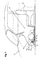
- Fig. 1 shows the footwell 2 of a motor vehicle 4 between a driver's seat 6 and foot pedals 8.
- an actuator 10 is used to act on these foot pedals 8 as part of an endurance test in the footwell 2.
- This example has two actuators 12 which are reciprocable by means of an actuator 14 back and forth to apply the foot pedals 8 recurrently with a compressive force,
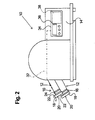
- the actuation elements 12 each have a force sensor 16, in particular from Fig. 2 can be seen.
- This force sensor 16 is provided on a loading plate 18 of the actuating element 12, which has a contact surface 20 for application to the foot pedal 8 to be acted upon.
- the contact surface 20 is dimensioned such that in the case of the usual vibrations during operation a secure contact with the respective foot pedal 8 is guaranteed, but on the other hand, an action on an adjacent foot pedal 8 can be ruled out.
- the force sensor 16 is provided on a side 22 facing away from the contact surface 20 of the loading plate 18.
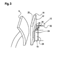
- the force sensor 16 has a strain sensor in the form of a strain gauge 24, which is provided on an elastic deformation element 26. This is exemplified by a bending beam 28 with an S-shaped profile 30 is formed.
- the strain gauge 24 extends over a region of the deformation element 26, which is deformed upon application of an application force from the actuating element 12 to the foot pedal 8. This deformation is converted by the strain gauge 24 into electrical signals, which can be given for example via a cable 32 on.
- the force sensor 16 via the cable 32 or wirelessly connected to an evaluation device 34.
- This receives the strain of the strip 24 as a function of the loading forces generated on the Beauftschungsplatte 18 übermittenen signals, this converts depending on the characteristics of the deformation element 26 in a corresponding current application force and displays this example on a display 36 at.
- an electronics 38 may be provided, via which the actuator 14 is controllable and in particular a memory for abspeichem various actuation profiles for the actuator 14 includes.
- various predetermined test curves can be stored in terms of data and retrieved as needed to actuate the actuator 14 such that the actuating element 12 acts on the relevant foot pedal 8 with the respective application profile corresponding Beaufschlagungs originally designed.
Landscapes
- Engineering & Computer Science (AREA)
- Transportation (AREA)
- Mechanical Engineering (AREA)
- Physics & Mathematics (AREA)
- General Physics & Mathematics (AREA)
- Braking Elements And Transmission Devices (AREA)
- Mechanical Control Devices (AREA)
- Braking Arrangements (AREA)
- Valves And Accessory Devices For Braking Systems (AREA)
Abstract
Description
- Die Erfindung betrifft eine Aktuatorvorrichtung zur Betätigung wenigstens eines Fußpedals eines Kraftfahrzeuges nach dem Oberbegriff des Anspruchs 1. Diese Aktuatorvorrichtung weist wenigstens ein Betätigungselement zur Betätigung wenigstens eines Fußpedals eines Kraftfahrzeuges auf. Dabei kann das Betätigungselement zur Beaufschlagung des Fußpedals mittels eines Stellantriebes angetrieben werden. Femer weist die Aktuatorvorrichtung einen Kraftsensor auf, mittels dem eine an einer Kontaktfläche des Betätigungselementes erzeugbare Beaufschlagungskrafit ermittelt beziehungsweise abgeleitet werden kann.
- Derartige Aktuatorvorrichtungen werden benötigt, um beispielsweise Funktions-und Dauertests der Fußpedale eines Kraftfahrzeuges, wie Gas-, Kupplungs- und Bremspedal, durchzuführen oder das Fahrzeug automatisiert beziehungsweise teilautomatisiert zu fahren. Hierbei führt die Aktuatorvorrichtung wiederkehrende Bewegungsabläufe zur Beaufschlagung der Fußpedate aus, die der tatsächlichen Betätigung der Fußpedale bei dem zu erwartenden Gebrauch des Fahrzeuges weitestgehend entsprechen.
- Aus
DE 24 15 095 A1 ist eine Betätigungsvorrichtung für ein Bremspedal bekannt, bei der ein Bremspedalkontaktkissen gegen das betreffende Pedal pressbar ist. Das Bremspedalkontaktkissen ist hierzu über ein Kugelgelenk an einer Kolbenstange einer Betätigungsvorrichtung gelagert. Um während des Betriebs eine tatsächlich auf das Bremspedal übertragene Kraft zu ermitteln, ist am Boden des Bremspedalkontaktkissens ein Bremskraftaufnehmer vorgesehen, der zusammen mit dem Bremspedalkontaktkissen gegen das betreffende Pedal gepresst wird. Femer sind zwei Mikroschalter vorgesehen, mittels denen ein Kontakt des Bremspedalkontaktkissens mit dem Pedal sowie eine Endanschlagstellung des Pedals detektierbar ist. - Nachteilig an der bekannten Aktuatorvorrichtung ist, dass deren Einbau und Ausrichtung in dem betreffenden Fahrzeug relativ aufwändig ist, da insbesondere das Bremspedalkontaktkissen und die Stößel der Mikroschalter sehr genau gegenüber dem Bremspedal und dem Fußraumboden des Fahrzeugs positioniert werden müssen, um einen störungsfreien Betrieb sicherstellen zu können. Zudem kann es auch bei exakter Voreinstellung insbesondere aufgrund von im Betrieb auftretenden Vibrationen zu Fehlfunktionen kommen, die beispielsweise durch veränderliche Positionen des Bremskraftaufnehmers gegenüber dem Pedal hervorgerufen werden.
- Die Aufgabe der Erfindung ist es, bei einer gattungsgemäßen Aktuatorvorrichtung die genannten Nachteile zu vermeiden und einen einfachen Einbau sowie einen störungsfreien Betrieb zu gewährleisten.
- Diese Aufgabe wird durch eine Aktuatorvorrichtung mit den Merkmalen des Anspruchs 1 gelöst. Dabei ist die Kontaktfläche durch eine Beaufschlagungsplatte gebildet und der Kraftsensor ist an einer von der Kontaktfläche abgewandten Seite der Beaufschlagungsplatte angeordnet. Hierbei kann mit dem Begriff Beaufschlagungsplatte jegliches Element bezeichnet sein, das kontaktflächenseitig eine im Wesentlichen ebene Flächenerstreckung aufweist, die insbesondere wenigstens der Breite eines handelsüblichen Fußpedals entspricht. Hierdurch greift der Kraftsensor die durch das Betätigungselement erzeugte Druckkraft nicht an der Kontaktfläche der Beaufschlagungsplatte sondem an deren Rückseite ab. Bei entsprechend steifer Ausführung der Beaufschlagungsplatte, wie beispielsweise bei Ausführung als Metallplatte, erreicht man hierdurch einerseits, dass der an der Rückseite abgegriffene Messwert im Wesentlichen identisch mit der an der Kontaktfläche erzeugten Druckkraft ist, wobei dieser Messwert andererseits im Wesentlichen unabhängig davon ist, an weicher Stelle der Kontaktfläche der Beaufschlagungskraft im Betrieb tatsächlich erzeugt wird. Hierdurch können Einflüsse von beispielsweise vibrationsbedingten Positionsänderungen des Betätigungselementes gegenüber dem Pedal auf die Messwerte des Kraftsensors vemachlässigt werden. Zudem ist es bei dieser Aktuatorvorrichtung ausreichend das Betätigungselement derart am betreffenden Pedal anzuordnen, dass lediglich eine sichere Beaufschlagung des Pedals gewährleistet ist. Hierüber hinausgehende Anforderungen bei der Positionierung der Betätigungsvorrichtung sind dagegen nicht erforderlich, was den Einbau der Aktuatorvorrichtung erheblich vereinfacht.
- In einer besonders vorteilhaften Ausführungsform weist der Kraftsensor einen Dehnungssensor an einem elastischen Verformungselement auf, das zwischen der Beaufschlagungsplatte und dem Stellantrieb angeordnet ist. Hierdurch ist eine besonders genaue Ermittlung einer an der Beaufschlagungsplatte im Betrieb auf tretenden Druckkraftbeanspruchung durch Erfassung einer daraus resultierenden Längenänderung des Verformungselementes, wie einer Stauchung oder Dehnung, möglich.
- Dabei ist es günstig, wenn das Verformungselement einen Biegebalken aufweist beziehungsweise durch diesen gebildet ist. Der Biegebalken kann dabei durch jedes bekannte geeignete elastische Material gebildet sein, wie beispielsweise aus einem Metall, wie insbesondere Aluminium oder Stahl, oder aus einem Kunststoff, wie insbesondere einem kohlefaserverstärkten Kunststoff. Ein solcher Biegebalken ermöglicht dabei einerseits die problemlose Übertragung auch relativ großer Druckkräfte. Andererseits kann durch dessen form- beziehungsweise materialbedingte Elastizität für die im Betrieb zu erwartenden Lastfälle eine stabile Federkonstante eingestellt werden.
- Besonders günstig ist es dabei, wenn der Biegebalken ein S-förmiges Profil aufweist. Hierdurch kann auch bei größerer Druckbeaufschlagung eine gewisse Par allelität eines antriebsseitigen Abschnittes und eines betätigungselementenseitigen Abschnittes des Verformungselementes sichergestellt werden.
- Vorteilhafterweise ist der Dehnungssensor durch einen Dehnungsmessstreifen gebildet. Hierdurch sind am Betätigungselement auch sehr geringfügige Druckspannungen detektierbar, wie sie beispielsweise beim bloßen Anlegen des Betätigungselementes an dem betreffenden Fußpedal auftreten. Andererseits können mit einem solchen Dehnungsmessstreifen auch sprunghaft ansteigende Druckbelastungen problemlos detektiert werden, wie sie beispielsweise beim Erreichen einer Endstellung des betreffenden Fußpedals auftreten. Somit kann durch Verwendung des Dehnungsmessstreifens als Dehnungssensor auf sonstige Sensoren beziehungsweise Detektionsmittel, wie beispielsweise Mikroschattervorrichtungen zum Erkennen der oben genannten Positionen, verzichtet werden.
- Zudem ist es günstig, wenn sich der Dehnungsmessstreifen hierbei über den S-förmigen Profilbereich des Verformungselementes erstreckt, wodurch auch sehr kleine Kraft- beziehungsweise Druckeinwirkungen durch den Dehnungsmessstreifen ermittelt werden können.
- Vorteilhafterweise ist der Kraftsensor zur Übermittlung von Signalen mit einer Auswertungseinrichtung verbunden. Diese ermöglicht eine Weiterbearbeitung der vom Kraftsensor ermittelten Messwerte, beispielsweise um diese dem Benutzer anzuzeigen oder um sie zur Steuerung des Stellantriebes zu verwenden.
- Femer ist es günstig, wenn der Stellantrieb von einer Elektronik steuerbar ist, mittels der ein Betätigungsprofil speicherbar und ausführbar ist. Hierdurch ist es möglich, bestimmte Testabläufe für einen bestimmten Typ von Fußpedalen vorab festzulegen und programmtechnisch zu speichern. Diese Tests können dann mittels der Aktuatorvorrichtung wiederkehrend an entsprechenden Fußpedalen durchgeführt werden, wodurch man vergleichbare Testergebnisse erhält.
- In einer weiteren vorteilhaften Ausführungsform ist die Elektronik zur Bildung eines Regelkreises mit der Auswertungseinrichtung verbunden. Hierdurch ist eine geregelte und somit besonders exakte vorbestimmte Beaufschlagung des betreffenden Fußpedals über die Aktuatorvorrichtung möglich.
- In den Figuren ist eine beispielhafte Ausführungsform der Erfindung dargestellt. Es zeigen:
- Figur 1
- eine Ansicht einer erfmdungsgemäßen Aktuatorvorrichtung im eingebauten Zustand,
- Figur 2
- eine Seitenansicht der Aktuatorvorrichtung nach
Fig 1 und - Figur 3
- eine perspektivische Ansicht eines pedalseitigen Endes eines Betätigungselementes der Aktuatorvonichtung nach
Fig, 1 . -
Fig. 1 zeigt den Fußraum 2 eines Kraftfahrzeuges 4 zwischen einem Fahrersitz 6 und Fußpedalen 8. Zur Beaufschlagung dieser Fußpedale 8 im Rahmen eines Dauertests ist in den Fußraum 2 eine Aktuatorvorrichtung 10 eingesetzt. Diese weist beispielhaft zwei Betätigungselemente 12 auf, die mittels eines Stellantriebes 14 hin- und her bewegbar sind, um die Fußpedale 8 wiederkehrend mit einer Druckkraft zu beaufschlagen, - Um die beim Beaufschlagen der Fußpedale 8 von der Aktuatorvorrichtung 10 erzeugten Beaufschlagungskräfte genau erfassen zu können, weisen die Betätigungselemente 12 jeweils einen Kraftsensor 16 auf, wie insbesondere aus
Fig. 2 zu entnehmen ist. Dieser Kraftsensor 16 ist an einer Beaufschlagungsplatte 18 des Betätigungselementes 12 vorgesehen, die eine Kontaktfläche 20 zum Anlegen an dem zu beaufschlagenden Fußpedal 8 aufweist. Die Kontaktfläche 20 ist dabei derart dimensioniert, dass bei den im Betrieb üblichen Vibrationen in jedem Fall eine sichere Anlage an dem betreffenden Fußpedal 8 gewährleistet ist aber andererseits eine Beaufschlagung eines benachbarten Fußpedals 8 ausgeschlossen werden kann. Der Kraftsensor 16 ist an einer von der Kontaktfläche 20 abgewandten Seite 22 der Beaufschlagungsplatte 18 vorgesehen. - Wie insbesondere aus
Fig. 3 zu entnehmen ist, weist der Kraftsensor 16 einen Dehnungssensor in Form eines Dehnungsmessstreifens 24 auf, der an einem elastischen Verformungselement 26 vorgesehen ist. Dieses ist beispielhaft durch einen Biegebalken 28 mit einem S-förmigen Profil 30 gebildet. Der Dehnungsmessstreifen 24 erstreckt sich dabei über einen Bereich des Verformungselementes 26 hinweg, der bei Aufbringung einer Beaufschlagungskraft vom Betätigungselement 12 auf das Fußpedal 8 verformt wird. Diese Verformung wird von dem Dehnungsmessstreifen 24 in elektrische Signale umgewandelt, die beispielsweise über ein Kabel 32 weiter gegebene werden können. - Wie aus
Fig. 2 zu entnehmen ist, ist der Kraftsensor 16 über das Kabel 32 oder auch kabellos mit einer Auswertungseinrichtung 34 verbunden. Diese empfängt die vom Dehnungsmessstreifen 24 in Abhängigkeit der an der Beaufschlagungsplatte 18 erzeugten Beaufschlagungskräfte übermittenen Signale, rechnet diese in Abhängigkeit der Kenngrößen des Verformungselementes 26 in eine entsprechende aktuelle Beaufschlagungskraft um und zeigt diese beispielsweise an einem Display 36 an. - Darüber hinaus kann eine Elektronik 38 vorgesehen sein, über die der Stellantrieb 14 steuerbar ist und die insbesondere einen Speicher zum abspeichem verschiedender Betätigungsprofile für den Stellantrieb 14 umfasst. Hierdurch können verschiedene vorbestimmte Testverläufe datenmäßig gespeichert und bei Bedarf abgerufen werden, um den Stellantrieb 14 derart anzusteuem, dass das Betätigungselement 12 das betreffende Fußpedal 8 mit den dem jeweiligen Betätigungsprofil entsprechenden Beaufschlagungskräften beaufschlagt.
- Ferner ist es möglich diese Elektronik 38 mit der Auswertungseinrichtung 32 zu verbinden, um im Betrieb einen von der Elektronik 38 vorgegebenen Sollwert der Beaufschlagungskraft mit einem tatsächlich an der Beaufschtagungsplatte 18 erzeugten Istwert der Beaufschlagungskraft kontinuierlich abgleichen zu können. Auf diese Weise bilden die Auswertungseinrichtung 32 und die Elektronik 34 zusammen mit dem Kraftsensor 16 einen Regelkreis, der eine direkte Regelung der am Fußpedal 8 erzeugten Beaufschlagungskräfte gewährleistet.
Claims (9)
- Aktuatorvorrichtung (10) zur Betätigung wenigstens eines Fußpedals (8) eines Kraftfahrzeuges (4)
mit wenigstens einem Betätigungselement (12), das zur Beaufschlagung des Fußpedal (8) mittels eines Stellantriebes (14) antreibbar ist, und
mit einem Kraftsensor (16), mittels dem eine an einer Kontaktfläche (20) des Betätigungselementes (12) erzeugbare Beaufschlagungskraft detektierbar ist,
dadurch gekennzeichnet, dass die Kontaktfläche (20) durch eine Beaufschlagungsplatte (18) gebildet ist und der Kraftsensor (16) an einer von der Kontaktfläche (20) abgewandten Seite (22) der Beaufschlagungsplatte (18) angeordnet ist. - Aktuatorvorrichtung nach Anspruch 1, dadurch gekennzeichnet, dass der Kraftsensor (16) einen Dehnungssensor an einem elastischen Verformungselement (26) aufweist, das zwischen der Beaufschlagungsplatte (18) und dem Steltantrieb (14) angeordnet ist.
- Aktuatorvorrichtung nach Anspruch 2, dadurch gekennzeichnet, dass das Verformungselement (26) durch einen Biegebalken (28) aufweist.
- Aktuatorvorrichtung nach Anspruch 3, dadurch gekennzeichnet, dass der Biegebalken (28) ein S-förmiges Profil (30) aufweist.
- Aktuatorvorrichtung nach einem der Ansprüche 2 bis 4, dadurch gekennzeichnet, dass der Dehnungssensor durch einen Dehnungsmessstreifen (24) gebildet ist.
- Aktuatorvorrichtung nach Anspruch 5, dadurch gekennzeichnet, dass sich der Dehnungsmessstreifen (24) über das S-förmige Profil (30) des Biegebalkens (28) erstreckt.
- Aktuatorvorrichtung nach einem der Ansprüche 1 bis 6, dadurch gekennzeichnet, dass der Kraftsensor (16) zur Übermittlung von Signalen mit einer Auswertungseinrichtung (34) verbunden ist.
- Aktuatorvorrichtung nach einem der Ansprüche 1 bis 7, dadurch gekennzeichnet, dass der Stellantrieb (14) von einer Elektronik (38) steuerbar ist, mittels der ein Betätigungsprofil speicherbar und ausführbar ist.
- Aktuatorvorrichtung nach Anspruch 8, dadurch gekennzeichnet, dass die Elektronik (38) zur Bildung eines Regelkreises mit der Auswertungseinrichtung (34) verbunden ist.
Applications Claiming Priority (1)
| Application Number | Priority Date | Filing Date | Title |
|---|---|---|---|
| DE102009056209A DE102009056209A1 (de) | 2009-11-28 | 2009-11-28 | Aktuatorvorrichtung mit Kraftsensor |
Publications (2)
| Publication Number | Publication Date |
|---|---|
| EP2330003A1 true EP2330003A1 (de) | 2011-06-08 |
| EP2330003B1 EP2330003B1 (de) | 2016-01-06 |
Family
ID=43595376
Family Applications (1)
| Application Number | Title | Priority Date | Filing Date |
|---|---|---|---|
| EP10014718.0A Not-in-force EP2330003B1 (de) | 2009-11-28 | 2010-11-18 | Aktuatorvorrichtung mit Kraftsensor |
Country Status (5)
| Country | Link |
|---|---|
| US (1) | US20110126642A1 (de) |
| EP (1) | EP2330003B1 (de) |
| JP (1) | JP5698502B2 (de) |
| DE (1) | DE102009056209A1 (de) |
| ES (1) | ES2563987T3 (de) |
Cited By (1)
| Publication number | Priority date | Publication date | Assignee | Title |
|---|---|---|---|---|
| WO2012048923A1 (de) * | 2010-10-13 | 2012-04-19 | Continental Teves Ag & Co. Ohg | Pedalstütze zum spannen eines bremspedals und verfahren zur überprüfung der dichtheit eines hydraulischen bremssystems |
Families Citing this family (5)
| Publication number | Priority date | Publication date | Assignee | Title |
|---|---|---|---|---|
| US8340863B2 (en) * | 2010-05-11 | 2012-12-25 | GM Global Technology Operations LLC | Vehicle pedal apparatus with user actuation sensor, and related operating method |
| CN102353532A (zh) * | 2011-10-12 | 2012-02-15 | 长春工业大学 | 汽车方向盘受力变形检测装置 |
| US9103737B2 (en) | 2013-03-08 | 2015-08-11 | Honda Motor Co., Ltd. | Vehicle brake system testing device and method |
| GB2576685B (en) * | 2018-01-17 | 2020-11-04 | Anthony Best Dynamics Ltd | Brake and accelerator robot |
| US11820356B2 (en) | 2019-12-20 | 2023-11-21 | Humanetics Austria Gmbh | System and method for force compensation in a robotic driving system |
Citations (5)
| Publication number | Priority date | Publication date | Assignee | Title |
|---|---|---|---|---|
| DE2415095A1 (de) | 1973-07-25 | 1975-02-13 | Clayton Manufacturing Co | Betaetigungsvorrichtung fuer ein bremspedal oder dergleichen |
| US3977241A (en) * | 1975-04-11 | 1976-08-31 | Clayton Manufacturing Company | Actuator unit for vehicle brake testing |
| DE4314731A1 (de) * | 1992-05-09 | 1993-11-11 | Horiba Ltd | Verfahren zur Steuerung eines Kraftfahrzeug-Fahrroboters |
| US5483825A (en) * | 1994-10-03 | 1996-01-16 | Ford Motor Company | Accelerator pedal system performance measurement apparatus |
| US20040255688A1 (en) * | 2003-06-18 | 2004-12-23 | Donghee Industrial Co., Ltd. | Device for measuring pedal-pushing force for vehicles |
Family Cites Families (20)
| Publication number | Priority date | Publication date | Assignee | Title |
|---|---|---|---|---|
| US3147617A (en) * | 1961-02-06 | 1964-09-08 | Gen Motors Corp | Accommodation checking device |
| US4020686A (en) * | 1976-01-05 | 1977-05-03 | Lebow Associates, Inc. | Force measuring apparatus |
| JPS5811828A (ja) * | 1981-07-15 | 1983-01-22 | Mitsubishi Electric Corp | 自動車運転ロボツト装置 |
| JPS6062497A (ja) * | 1983-09-14 | 1985-04-10 | 畑村 洋太郎 | 多軸力センサ |
| US4621525A (en) * | 1984-12-17 | 1986-11-11 | Ford Motor Company | Accelerator pedal actuator system for automatic driving system |
| DE3525864C1 (de) * | 1985-07-19 | 1986-11-20 | Bayerische Motoren Werke AG, 8000 München | Tragbare Bremsdruckprüfvorrichtung |
| ATE43181T1 (de) * | 1986-03-08 | 1989-06-15 | Schenck Ag Carl | Verfahren zur automatischen bewegung eines kraftfahrzeugbetaetigungsteils sowie vorrichtung zur durchfuehrung des verfahrens. |
| US5012689A (en) * | 1989-10-04 | 1991-05-07 | Smith Steven R | Vehicle foot pedal actuator apparatus and method |
| DE3940588A1 (de) * | 1989-12-08 | 1991-06-13 | Georg Witt | Fahrroboter |
| JPH0619307B2 (ja) * | 1990-12-30 | 1994-03-16 | 株式会社堀場製作所 | 自動車自動運転ロボットの制御方法 |
| JPH0743296B2 (ja) * | 1991-01-16 | 1995-05-15 | 株式会社堀場製作所 | 自動車自動運転ロボットの制御方法 |
| JP2613517B2 (ja) * | 1991-12-07 | 1997-05-28 | 株式会社堀場製作所 | シャシダイナモメータ上の自動車運転用ロボット |
| US5299668A (en) * | 1992-02-11 | 1994-04-05 | Youngers William L | Assembly for depressing a vehicle pedal for bleeding brakes |
| US5442146A (en) * | 1992-04-03 | 1995-08-15 | Weigh-Tronix, Inc. | Counting scale and load cell assembly therefor |
| GB2322354B (en) * | 1997-02-25 | 2000-05-10 | Fki Engineering Plc | Robot for operating motor vehicle control |
| JP2001278016A (ja) * | 2000-03-30 | 2001-10-10 | Banzai Ltd | 車両のホイールアライメントテスト用ブレーキロック装置 |
| JP2002286590A (ja) * | 2001-03-23 | 2002-10-03 | Toyota Motor Corp | 操作部材の自動押圧による車輌性能評価試験方法及び装置 |
| US7021131B2 (en) * | 2003-10-06 | 2006-04-04 | Daimlerchrysler Corporation | Fixture for supporting a brake pedal tester |
| JP4514547B2 (ja) * | 2004-08-05 | 2010-07-28 | 株式会社タニタ | ロードセル |
| US7733448B2 (en) * | 2004-10-29 | 2010-06-08 | Semiconductor Energy Laboratory Co., Ltd. | Liquid crystal display device |
-
2009
- 2009-11-28 DE DE102009056209A patent/DE102009056209A1/de not_active Ceased
-
2010
- 2010-11-18 EP EP10014718.0A patent/EP2330003B1/de not_active Not-in-force
- 2010-11-18 ES ES10014718.0T patent/ES2563987T3/es active Active
- 2010-11-26 JP JP2010263126A patent/JP5698502B2/ja not_active Expired - Fee Related
- 2010-11-29 US US12/955,294 patent/US20110126642A1/en not_active Abandoned
Patent Citations (5)
| Publication number | Priority date | Publication date | Assignee | Title |
|---|---|---|---|---|
| DE2415095A1 (de) | 1973-07-25 | 1975-02-13 | Clayton Manufacturing Co | Betaetigungsvorrichtung fuer ein bremspedal oder dergleichen |
| US3977241A (en) * | 1975-04-11 | 1976-08-31 | Clayton Manufacturing Company | Actuator unit for vehicle brake testing |
| DE4314731A1 (de) * | 1992-05-09 | 1993-11-11 | Horiba Ltd | Verfahren zur Steuerung eines Kraftfahrzeug-Fahrroboters |
| US5483825A (en) * | 1994-10-03 | 1996-01-16 | Ford Motor Company | Accelerator pedal system performance measurement apparatus |
| US20040255688A1 (en) * | 2003-06-18 | 2004-12-23 | Donghee Industrial Co., Ltd. | Device for measuring pedal-pushing force for vehicles |
Cited By (2)
| Publication number | Priority date | Publication date | Assignee | Title |
|---|---|---|---|---|
| WO2012048923A1 (de) * | 2010-10-13 | 2012-04-19 | Continental Teves Ag & Co. Ohg | Pedalstütze zum spannen eines bremspedals und verfahren zur überprüfung der dichtheit eines hydraulischen bremssystems |
| US9050960B2 (en) | 2010-10-13 | 2015-06-09 | Continental Teves Ag & Co. Ohg | Pedal prop for imposing a load on a brake pedal and method for checking the sealing of one or more components of a hydraulic brake system |
Also Published As
| Publication number | Publication date |
|---|---|
| JP5698502B2 (ja) | 2015-04-08 |
| US20110126642A1 (en) | 2011-06-02 |
| DE102009056209A1 (de) | 2011-07-07 |
| EP2330003B1 (de) | 2016-01-06 |
| ES2563987T3 (es) | 2016-03-17 |
| JP2011111159A (ja) | 2011-06-09 |
Similar Documents
| Publication | Publication Date | Title |
|---|---|---|
| EP2330003B1 (de) | Aktuatorvorrichtung mit Kraftsensor | |
| DE2928153C2 (de) | Bremsentestvorrichtung | |
| EP2326539B1 (de) | Verbindungselement zur messung einer betätigungskraft einer fahrzeugbremsanlage | |
| DE102008015873A1 (de) | Fahrzeug, insbesondere Schienenfahrzeug, mit einer Einrichtung zur Überwachung der Bremswirkung | |
| DE112017004864T5 (de) | Pedalvorrichtung | |
| DE3710256A1 (de) | Sollwertgeber | |
| WO2013149744A1 (de) | Bremsbetätigungs-sensorvorrichtung für ein bremssystem eines fahrzeugs und verfahren zum montieren einer bremsbetätigungs-sensorvorrichtung an einem bremssystem eines fahrzeugs | |
| DE102009004424A1 (de) | Scheibenbremse | |
| DE102009051352A1 (de) | Scheibenbremsvorrichtung für Schienenfahrzeuge | |
| DE102022106983A1 (de) | Vorrichtung zur Fahrerwunscherfassung | |
| WO2018036867A1 (de) | Erfassungssystem zur detektion einer betätigung bei einer griffvorrichtung eines fahrzeuges | |
| WO2013153048A1 (de) | Bedieneinheit für eine fahrzeugkomponente | |
| EP1654473B1 (de) | Kraftfahrzeugbremse | |
| WO2008122501A1 (de) | Tasteranordnung zur erfassung der schaltstellung eines getriebes sowie getriebe mit der tasteranordnung | |
| EP0259471B1 (de) | Vorrichtung zur überprüfung und/oder erfassung der masse, massaenderungen, positionen oder positionsaenderungen von werkstuecken, stellgliedern oder gdl. | |
| EP2609477B1 (de) | Pedalwertgeberanordnung | |
| EP1456553B1 (de) | Verfahren zur ermittlung des kupplungsanlegepunktes | |
| DE102011002567A1 (de) | Scheibenbremse sowie Verfahren zur Ermittlung einer wirkenden Bremskraft oder eines wirkenden Bremsmoments | |
| EP3164619B1 (de) | Bremssystem | |
| DE102016203623A1 (de) | Vorrichtung zur Kraftsimulation an einem Betätigungselement eines Fahrzeuges, vorzugsweise ein Pedalkraftsimulator | |
| EP2452762B1 (de) | Vorrichtung zum Überprüfen der Presskraft eines Presswerkzeuges | |
| DE102015105349B4 (de) | Bremszylinder eines Kraftfahrzeugs | |
| DE102006044908B4 (de) | Pedalvorrichtung mit einem Auslöseelement | |
| DE102012217859A1 (de) | Vorrichtung und System zum Messen einer Zugkraft in einem Zugseil | |
| DE10029742C2 (de) | Vorrichtung zur Kraftmessung mittels Erfassen geringfügiger Längenänderungen |
Legal Events
| Date | Code | Title | Description |
|---|---|---|---|
| PUAI | Public reference made under article 153(3) epc to a published international application that has entered the european phase |
Free format text: ORIGINAL CODE: 0009012 |
|
| AK | Designated contracting states |
Kind code of ref document: A1 Designated state(s): AL AT BE BG CH CY CZ DE DK EE ES FI FR GB GR HR HU IE IS IT LI LT LU LV MC MK MT NL NO PL PT RO RS SE SI SK SM TR |
|
| AX | Request for extension of the european patent |
Extension state: BA ME |
|
| 17P | Request for examination filed |
Effective date: 20111208 |
|
| 17Q | First examination report despatched |
Effective date: 20120418 |
|
| GRAP | Despatch of communication of intention to grant a patent |
Free format text: ORIGINAL CODE: EPIDOSNIGR1 |
|
| INTG | Intention to grant announced |
Effective date: 20150716 |
|
| GRAS | Grant fee paid |
Free format text: ORIGINAL CODE: EPIDOSNIGR3 |
|
| GRAA | (expected) grant |
Free format text: ORIGINAL CODE: 0009210 |
|
| AK | Designated contracting states |
Kind code of ref document: B1 Designated state(s): AL AT BE BG CH CY CZ DE DK EE ES FI FR GB GR HR HU IE IS IT LI LT LU LV MC MK MT NL NO PL PT RO RS SE SI SK SM TR |
|
| REG | Reference to a national code |
Ref country code: GB Ref legal event code: FG4D Free format text: NOT ENGLISH |
|
| REG | Reference to a national code |
Ref country code: CH Ref legal event code: EP |
|
| REG | Reference to a national code |
Ref country code: IE Ref legal event code: FG4D Free format text: LANGUAGE OF EP DOCUMENT: GERMAN |
|
| REG | Reference to a national code |
Ref country code: AT Ref legal event code: REF Ref document number: 768577 Country of ref document: AT Kind code of ref document: T Effective date: 20160215 |
|
| REG | Reference to a national code |
Ref country code: DE Ref legal event code: R096 Ref document number: 502010010850 Country of ref document: DE |
|
| REG | Reference to a national code |
Ref country code: ES Ref legal event code: FG2A Ref document number: 2563987 Country of ref document: ES Kind code of ref document: T3 Effective date: 20160317 |
|
| REG | Reference to a national code |
Ref country code: SE Ref legal event code: TRGR |
|
| REG | Reference to a national code |
Ref country code: LT Ref legal event code: MG4D |
|
| REG | Reference to a national code |
Ref country code: NL Ref legal event code: MP Effective date: 20160106 |
|
| PG25 | Lapsed in a contracting state [announced via postgrant information from national office to epo] |
Ref country code: NL Free format text: LAPSE BECAUSE OF FAILURE TO SUBMIT A TRANSLATION OF THE DESCRIPTION OR TO PAY THE FEE WITHIN THE PRESCRIBED TIME-LIMIT Effective date: 20160106 |
|
| PG25 | Lapsed in a contracting state [announced via postgrant information from national office to epo] |
Ref country code: NO Free format text: LAPSE BECAUSE OF FAILURE TO SUBMIT A TRANSLATION OF THE DESCRIPTION OR TO PAY THE FEE WITHIN THE PRESCRIBED TIME-LIMIT Effective date: 20160406 Ref country code: FI Free format text: LAPSE BECAUSE OF FAILURE TO SUBMIT A TRANSLATION OF THE DESCRIPTION OR TO PAY THE FEE WITHIN THE PRESCRIBED TIME-LIMIT Effective date: 20160106 Ref country code: GR Free format text: LAPSE BECAUSE OF FAILURE TO SUBMIT A TRANSLATION OF THE DESCRIPTION OR TO PAY THE FEE WITHIN THE PRESCRIBED TIME-LIMIT Effective date: 20160407 Ref country code: HR Free format text: LAPSE BECAUSE OF FAILURE TO SUBMIT A TRANSLATION OF THE DESCRIPTION OR TO PAY THE FEE WITHIN THE PRESCRIBED TIME-LIMIT Effective date: 20160106 |
|
| PG25 | Lapsed in a contracting state [announced via postgrant information from national office to epo] |
Ref country code: LV Free format text: LAPSE BECAUSE OF FAILURE TO SUBMIT A TRANSLATION OF THE DESCRIPTION OR TO PAY THE FEE WITHIN THE PRESCRIBED TIME-LIMIT Effective date: 20160106 Ref country code: PL Free format text: LAPSE BECAUSE OF FAILURE TO SUBMIT A TRANSLATION OF THE DESCRIPTION OR TO PAY THE FEE WITHIN THE PRESCRIBED TIME-LIMIT Effective date: 20160106 Ref country code: IS Free format text: LAPSE BECAUSE OF FAILURE TO SUBMIT A TRANSLATION OF THE DESCRIPTION OR TO PAY THE FEE WITHIN THE PRESCRIBED TIME-LIMIT Effective date: 20160506 Ref country code: RS Free format text: LAPSE BECAUSE OF FAILURE TO SUBMIT A TRANSLATION OF THE DESCRIPTION OR TO PAY THE FEE WITHIN THE PRESCRIBED TIME-LIMIT Effective date: 20160106 Ref country code: PT Free format text: LAPSE BECAUSE OF FAILURE TO SUBMIT A TRANSLATION OF THE DESCRIPTION OR TO PAY THE FEE WITHIN THE PRESCRIBED TIME-LIMIT Effective date: 20160506 Ref country code: LT Free format text: LAPSE BECAUSE OF FAILURE TO SUBMIT A TRANSLATION OF THE DESCRIPTION OR TO PAY THE FEE WITHIN THE PRESCRIBED TIME-LIMIT Effective date: 20160106 |
|
| REG | Reference to a national code |
Ref country code: DE Ref legal event code: R097 Ref document number: 502010010850 Country of ref document: DE |
|
| PG25 | Lapsed in a contracting state [announced via postgrant information from national office to epo] |
Ref country code: EE Free format text: LAPSE BECAUSE OF FAILURE TO SUBMIT A TRANSLATION OF THE DESCRIPTION OR TO PAY THE FEE WITHIN THE PRESCRIBED TIME-LIMIT Effective date: 20160106 Ref country code: DK Free format text: LAPSE BECAUSE OF FAILURE TO SUBMIT A TRANSLATION OF THE DESCRIPTION OR TO PAY THE FEE WITHIN THE PRESCRIBED TIME-LIMIT Effective date: 20160106 |
|
| PLBE | No opposition filed within time limit |
Free format text: ORIGINAL CODE: 0009261 |
|
| STAA | Information on the status of an ep patent application or granted ep patent |
Free format text: STATUS: NO OPPOSITION FILED WITHIN TIME LIMIT |
|
| PG25 | Lapsed in a contracting state [announced via postgrant information from national office to epo] |
Ref country code: SM Free format text: LAPSE BECAUSE OF FAILURE TO SUBMIT A TRANSLATION OF THE DESCRIPTION OR TO PAY THE FEE WITHIN THE PRESCRIBED TIME-LIMIT Effective date: 20160106 Ref country code: RO Free format text: LAPSE BECAUSE OF FAILURE TO SUBMIT A TRANSLATION OF THE DESCRIPTION OR TO PAY THE FEE WITHIN THE PRESCRIBED TIME-LIMIT Effective date: 20160106 Ref country code: SK Free format text: LAPSE BECAUSE OF FAILURE TO SUBMIT A TRANSLATION OF THE DESCRIPTION OR TO PAY THE FEE WITHIN THE PRESCRIBED TIME-LIMIT Effective date: 20160106 |
|
| 26N | No opposition filed |
Effective date: 20161007 |
|
| PG25 | Lapsed in a contracting state [announced via postgrant information from national office to epo] |
Ref country code: BG Free format text: LAPSE BECAUSE OF FAILURE TO SUBMIT A TRANSLATION OF THE DESCRIPTION OR TO PAY THE FEE WITHIN THE PRESCRIBED TIME-LIMIT Effective date: 20160406 Ref country code: SI Free format text: LAPSE BECAUSE OF FAILURE TO SUBMIT A TRANSLATION OF THE DESCRIPTION OR TO PAY THE FEE WITHIN THE PRESCRIBED TIME-LIMIT Effective date: 20160106 Ref country code: BE Free format text: LAPSE BECAUSE OF NON-PAYMENT OF DUE FEES Effective date: 20161130 |
|
| REG | Reference to a national code |
Ref country code: CH Ref legal event code: PL |
|
| REG | Reference to a national code |
Ref country code: SE Ref legal event code: EUG |
|
| GBPC | Gb: european patent ceased through non-payment of renewal fee |
Effective date: 20161118 |
|
| PG25 | Lapsed in a contracting state [announced via postgrant information from national office to epo] |
Ref country code: CH Free format text: LAPSE BECAUSE OF NON-PAYMENT OF DUE FEES Effective date: 20161130 Ref country code: LI Free format text: LAPSE BECAUSE OF NON-PAYMENT OF DUE FEES Effective date: 20161130 |
|
| REG | Reference to a national code |
Ref country code: IE Ref legal event code: MM4A |
|
| REG | Reference to a national code |
Ref country code: FR Ref legal event code: ST Effective date: 20170731 |
|
| PG25 | Lapsed in a contracting state [announced via postgrant information from national office to epo] |
Ref country code: SE Free format text: LAPSE BECAUSE OF NON-PAYMENT OF DUE FEES Effective date: 20161119 |
|
| PG25 | Lapsed in a contracting state [announced via postgrant information from national office to epo] |
Ref country code: LU Free format text: LAPSE BECAUSE OF NON-PAYMENT OF DUE FEES Effective date: 20161130 |
|
| PG25 | Lapsed in a contracting state [announced via postgrant information from national office to epo] |
Ref country code: FR Free format text: LAPSE BECAUSE OF NON-PAYMENT OF DUE FEES Effective date: 20161130 |
|
| PG25 | Lapsed in a contracting state [announced via postgrant information from national office to epo] |
Ref country code: GB Free format text: LAPSE BECAUSE OF NON-PAYMENT OF DUE FEES Effective date: 20161118 Ref country code: IE Free format text: LAPSE BECAUSE OF NON-PAYMENT OF DUE FEES Effective date: 20161118 |
|
| REG | Reference to a national code |
Ref country code: AT Ref legal event code: MM01 Ref document number: 768577 Country of ref document: AT Kind code of ref document: T Effective date: 20161118 |
|
| PG25 | Lapsed in a contracting state [announced via postgrant information from national office to epo] |
Ref country code: AT Free format text: LAPSE BECAUSE OF NON-PAYMENT OF DUE FEES Effective date: 20161118 |
|
| PGFP | Annual fee paid to national office [announced via postgrant information from national office to epo] |
Ref country code: CZ Payment date: 20171107 Year of fee payment: 8 |
|
| REG | Reference to a national code |
Ref country code: BE Ref legal event code: MM Effective date: 20161130 |
|
| REG | Reference to a national code |
Ref country code: DE Ref legal event code: R082 Ref document number: 502010010850 Country of ref document: DE Representative=s name: WACKER, JOST, DIPL.-ING., DE |
|
| PGFP | Annual fee paid to national office [announced via postgrant information from national office to epo] |
Ref country code: IT Payment date: 20171122 Year of fee payment: 8 |
|
| PG25 | Lapsed in a contracting state [announced via postgrant information from national office to epo] |
Ref country code: ES Free format text: LAPSE BECAUSE OF NON-PAYMENT OF DUE FEES Effective date: 20171119 Ref country code: HU Free format text: LAPSE BECAUSE OF FAILURE TO SUBMIT A TRANSLATION OF THE DESCRIPTION OR TO PAY THE FEE WITHIN THE PRESCRIBED TIME-LIMIT; INVALID AB INITIO Effective date: 20101118 Ref country code: CY Free format text: LAPSE BECAUSE OF FAILURE TO SUBMIT A TRANSLATION OF THE DESCRIPTION OR TO PAY THE FEE WITHIN THE PRESCRIBED TIME-LIMIT Effective date: 20160106 |
|
| PG25 | Lapsed in a contracting state [announced via postgrant information from national office to epo] |
Ref country code: MC Free format text: LAPSE BECAUSE OF FAILURE TO SUBMIT A TRANSLATION OF THE DESCRIPTION OR TO PAY THE FEE WITHIN THE PRESCRIBED TIME-LIMIT Effective date: 20160106 Ref country code: MK Free format text: LAPSE BECAUSE OF FAILURE TO SUBMIT A TRANSLATION OF THE DESCRIPTION OR TO PAY THE FEE WITHIN THE PRESCRIBED TIME-LIMIT Effective date: 20160106 Ref country code: TR Free format text: LAPSE BECAUSE OF FAILURE TO SUBMIT A TRANSLATION OF THE DESCRIPTION OR TO PAY THE FEE WITHIN THE PRESCRIBED TIME-LIMIT Effective date: 20160106 |
|
| PG25 | Lapsed in a contracting state [announced via postgrant information from national office to epo] |
Ref country code: MT Free format text: LAPSE BECAUSE OF FAILURE TO SUBMIT A TRANSLATION OF THE DESCRIPTION OR TO PAY THE FEE WITHIN THE PRESCRIBED TIME-LIMIT Effective date: 20160106 |
|
| PG25 | Lapsed in a contracting state [announced via postgrant information from national office to epo] |
Ref country code: AL Free format text: LAPSE BECAUSE OF FAILURE TO SUBMIT A TRANSLATION OF THE DESCRIPTION OR TO PAY THE FEE WITHIN THE PRESCRIBED TIME-LIMIT Effective date: 20160106 |
|
| REG | Reference to a national code |
Ref country code: ES Ref legal event code: FD2A Effective date: 20181112 |
|
| PGFP | Annual fee paid to national office [announced via postgrant information from national office to epo] |
Ref country code: DE Payment date: 20180921 Year of fee payment: 9 |
|
| RIC2 | Information provided on ipc code assigned after grant |
Ipc: G05G 1/54 20080401ALI20110302BHEP Ipc: B60T 17/22 20060101ALI20110302BHEP Ipc: G01L 5/28 20060101ALI20110302BHEP Ipc: B60T 7/04 20060101AFI20110302BHEP Ipc: G01L 5/22 20060101ALI20110302BHEP |
|
| PG25 | Lapsed in a contracting state [announced via postgrant information from national office to epo] |
Ref country code: ES Free format text: LAPSE BECAUSE OF NON-PAYMENT OF DUE FEES Effective date: 20161119 |
|
| PG25 | Lapsed in a contracting state [announced via postgrant information from national office to epo] |
Ref country code: CZ Free format text: LAPSE BECAUSE OF NON-PAYMENT OF DUE FEES Effective date: 20181118 |
|
| PG25 | Lapsed in a contracting state [announced via postgrant information from national office to epo] |
Ref country code: IT Free format text: LAPSE BECAUSE OF NON-PAYMENT OF DUE FEES Effective date: 20181118 |
|
| REG | Reference to a national code |
Ref country code: DE Ref legal event code: R119 Ref document number: 502010010850 Country of ref document: DE |
|
| PG25 | Lapsed in a contracting state [announced via postgrant information from national office to epo] |
Ref country code: DE Free format text: LAPSE BECAUSE OF NON-PAYMENT OF DUE FEES Effective date: 20200603 |