EP2329241B1 - Vorrichtung zur druckmessung von medien in hohlkörpern; verfahren zur messung des drucks von medien in hohlkörpern - Google Patents
Vorrichtung zur druckmessung von medien in hohlkörpern; verfahren zur messung des drucks von medien in hohlkörpern Download PDFInfo
- Publication number
- EP2329241B1 EP2329241B1 EP09744931.8A EP09744931A EP2329241B1 EP 2329241 B1 EP2329241 B1 EP 2329241B1 EP 09744931 A EP09744931 A EP 09744931A EP 2329241 B1 EP2329241 B1 EP 2329241B1
- Authority
- EP
- European Patent Office
- Prior art keywords
- measuring
- expansion
- recess
- pressure
- carried out
- Prior art date
- Legal status (The legal status is an assumption and is not a legal conclusion. Google has not performed a legal analysis and makes no representation as to the accuracy of the status listed.)
- Active
Links
- 238000000034 method Methods 0.000 title claims description 16
- 238000005259 measurement Methods 0.000 claims description 11
- 238000009530 blood pressure measurement Methods 0.000 claims description 8
- 230000003287 optical effect Effects 0.000 claims description 8
- 239000003990 capacitor Substances 0.000 claims description 6
- 230000001419 dependent effect Effects 0.000 claims description 5
- 239000012528 membrane Substances 0.000 description 3
- 238000006243 chemical reaction Methods 0.000 description 2
- 238000001514 detection method Methods 0.000 description 2
- 238000001746 injection moulding Methods 0.000 description 2
- 238000013461 design Methods 0.000 description 1
- 238000006073 displacement reaction Methods 0.000 description 1
- 238000005516 engineering process Methods 0.000 description 1
- 238000002474 experimental method Methods 0.000 description 1
- 230000001939 inductive effect Effects 0.000 description 1
- 239000000463 material Substances 0.000 description 1
- 238000000691 measurement method Methods 0.000 description 1
- 230000002787 reinforcement Effects 0.000 description 1
- 238000004904 shortening Methods 0.000 description 1
- 238000012360 testing method Methods 0.000 description 1
Images




Classifications
-
- G—PHYSICS
- G01—MEASURING; TESTING
- G01L—MEASURING FORCE, STRESS, TORQUE, WORK, MECHANICAL POWER, MECHANICAL EFFICIENCY, OR FLUID PRESSURE
- G01L9/00—Measuring steady of quasi-steady pressure of fluid or fluent solid material by electric or magnetic pressure-sensitive elements; Transmitting or indicating the displacement of mechanical pressure-sensitive elements, used to measure the steady or quasi-steady pressure of a fluid or fluent solid material, by electric or magnetic means
- G01L9/0001—Transmitting or indicating the displacement of elastically deformable gauges by electric, electro-mechanical, magnetic or electro-magnetic means
Definitions
- the invention relates to a measuring device and a method for measuring at least one measured variable, in particular pressure of media.
- measuring systems that are installed close to the process are used to acquire process variables that are installed directly on the media container or a feeder.
- measuring systems each have a corresponding sensor which is inserted in the course of a medium-conducting process line and which serves to generate at least one measuring signal which represents the primarily detected measured variable as accurately as possible, in particular electrical.
- the measuring sensor is usually provided with a measuring tube serving in the course of the respective process line, the guiding of flowing medium and a corresponding physical-electrical sensor arrangement fitted. This, in turn, has at least one sensor element which reacts primarily to the measured quantity to be detected or else changes thereof, by means of which at least one measuring signal influenced accordingly by the measured variable is generated during operation.
- Pressure sensors usually consist of a mechanical sensor, for example a membrane, and an electrical sensor necessary for the detection of a measured variable, for example a displacement or a force, of the mechanical sensor, for example a distance sensor.
- the mechanical sensor and the distance sensor are integrated in a common, external housing.
- the pressure sensor is in direct contact with the medium.
- the known measuring systems often require sensors for measuring measured variables, in particular for measuring pressures of the media flowing through, which engage in the region within the flow body.
- a “method for noninvasive internal pressure measurement in elastic vessels” is known (US Pat. DE 197 47 254 C2 ), in which a vessel is deformed from the outside by applying a force and a reaction force is measured without the vessel surface has to be changed nor a connection between the vessel interior and the measuring sensor is required. Thereafter, the relaxation function of the hose is mathematically determined with a predetermined type of function, which depends on the material used of the hose, whose parameters are calculated from the measured reaction forces.
- the mechanical sensor acts like a membrane or is membrane-like, ie. H. that the deflection of the mechanical sensor behaves similar to the deflection of a membrane, or the mechanical sensor has the properties of a thin or thick disk.
- the sensor is positioned, for example, on the bottom of a blind hole.
- the measuring device is a measuring body for detecting pressure of any quiescent or flowing media in the embodiment of a deformed body whose wall thickness is specifically weakened. It is therefore in an advantageous embodiment of a strain-ring pressure sensor, which consists in its simplest embodiment of a cylindrical tube, the has a slot in the longitudinal direction. However, all geometric shapes are conceivable as a design for this measuring body. This measuring body is designed as an intrinsic sensor.
- the weakened region itself can be embodied differently shaped, for example in V-shape, as an orthogonal or U-shaped groove, as a cut-through bore or with a cross-section formed as a circular segment or the like.
- the detection of the pressure-dependent expansion is detected by any measuring principles or measuring methods, for example by length measurement, optical length measurement, with strain gauges, capacitive, inductive, purely mechanical, hydraulic, pneumatic or the like.
- the configuration of the measuring body can be used several times in succession, for example in the longitudinal direction the flow of the medium as differential pressure measurement at at least two measuring points.
- the senor in measuring the widening of the slot, is positioned on the surface of the tube in the immediate vicinity of the slot.
- the width change ie the widening of the slot, is measured by the sensor.
- the slot width is chosen to be close to zero, whereby the temperature coefficient of the zero point of the system also tends to zero.
- the application is as a sphygmomanometer or disposable sensor in medical technology, but also for highly dynamic pressure measurement directly in nozzles, for example in injection molding.
- the measuring body can be retrofitted in a connecting part of an existing machine, for. B. in the measurement of hydraulic pressure.
- the measuring body works non-invasively, d. H. that no sensor protruding into the medium is present, which affects the smooth inner surfaces of the flow body.
- the medium-carrying bore can be adapted to the shape of the flow channel, so that cavitative forms are continued.
- slot-shaped cross sections of flow bodies as well as cross-sectional narrowing or widening shapes and combinations of all embodiments can be realized.
- the measuring body is an integral part of the media-leading system, so for example, the media supply line or the nozzle, for example an injection molding machine itself.
- Fig. 1 shows a cross section through a tube (deformed body 1) with a nearly circular inner mold 2 and a groove-shaped recess 3 in the outer periphery 4 of the tube.
- the depth of the recess 3 (slot) is significantly greater than the width of the slot (see Fig. 2 , Recess edge 6 to recess edge 6).
- Fig. 2 is this tube, in which the groove-shaped recess 3 is widened in the outer periphery 4, shown, wherein the expansion of the circular inner mold 2 towards an ellipsoidal inner mold 5 is carried out and the two outer recess edges 6 of the groove-shaped recess 3 are pressed apart.
- Fig. 3 shows the deformation of the cross section A of the tube, for example, at an internal pressure of 500 bar in 100-fold inflated representation.
- the point F in values determined during a test series is shifted by 0.0304 mm in the y-direction, which corresponds to an elongation of 6100 ppm in relation to half the groove width of 5 mm.
- the stresses are at their maximum values of 623 MPa above the targeted maximum stress of 250 MPa, whereby a much higher strain than necessary is present. Therefore, a residual wall thickness is optimal, allowing a shape that is within the range of over 1300 ppm elongation and a maximum stress of less than 250 MPa.
- cross-section A (6100 ppm / 623 MPa): 4.8 cross-section B: (6580 ppm / 619 MPa): 9.8 cross-section C: (1700 ppm / 212 MPa): 10.6 cross-section D: (14500 ppm / 969 MPa): 8.0 cross-section e: (4080 ppm / 204 MPa): 20.0
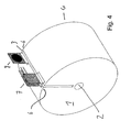
- Fig. 4 shows by way of example schematically two capacitors 7, 8 which are arranged on the recess edge 6, wherein the second capacitor 8, only one half is shown for purposes of illustration. If the pressure in the inner tube 2 changes, the gap, that is to say the recess 3, is widened. Due to the radial arrangement of the gap, the expansion at the outer end is greater than in the vicinity of the inner tube 2. As a result, the signal is amplified several times, which is recorded with the capacitors 7, 8 by means of capacitance change.
- Fig. 5 shows by way of example two optical measuring systems 9, 10, which detect the widening of the slot by means of optical length measurement.
- the measuring systems eg the measuring systems 9, 10) can be arranged at least partially submerged in the widening.
- Fig. 6 shows by way of example two strain gauges 19, 20, which measure by way of example by means of wires 21, 22, the widening 3 of the slot.
- the Wheatstone circuit principle is in Fig. 6a shown. As the pressure in the tube increases, the gap widens, stretching the first wire 21 and increasing its resistance and shortening the second wire 22 and reducing its resistance.
Landscapes
- Physics & Mathematics (AREA)
- General Physics & Mathematics (AREA)
- Measuring Fluid Pressure (AREA)
Description
- Die Erfindung betrifft eine Messvorrichtung sowie ein Verfahren zum Messen wenigstens einer Messgröße, insbesondere von Druck von Medien.
- In der Messtechnik werden zur Erfassung von Messgrößen prozessnah installierte Messsysteme verwendet, die jeweils direkt an dem Mediumsbehälter oder einer Zuführung angebracht sind. Zum Erfassen der jeweiligen Messgrößen weisen Messsysteme jeweils einen entsprechenden Messaufnehmer auf, der in den Verlauf einer Medium führenden Prozessleitung eingesetzt ist und der dazu dient, wenigstens ein die primär erfasste Messgröße möglichst genau repräsentierendes, insbesondere elektrisches, Messsignal zu erzeugen. Dafür ist der Messaufnehmer üblicherweise mit einem in den Verlauf der jeweiligen Prozessleitung, dem Führen von strömendem Medium dienenden Messrohr sowie eine entsprechende physikalisch-elektrische Sensoranordnung ausgestattet. Diese wiederum weist wenigstens ein primär auf die zu erfassende Messgröße oder auch Änderungen derselben reagierendes Sensorelement auf, mittels dem im Betrieb wenigstens ein von der Messgröße entsprechend beeinflusstes Messsignal erzeugt wird.
- Drucksensoren bestehen üblicherweise aus einem mechanischen Messaufnehmer, beispielsweise einer Membran, und einem zur Detektion einer Messgröße, beispielsweise einer Auslenkung oder einer Kraft, des mechanischen Messaufnehmers notwendigen elektischen Sensors, beispielsweise einem Abstandssensor. Der mechanische Messaufnehmer und der Abstandssensor sind dabei in einem gemeinsamen, externen Gehäuse integriert. Der Drucksensor steht dabei in direktem Kontakt mit dem Medium.
- Die bekannten Messsysteme benötigen häufig zur Messung von Messgrößen, insbesondere zum Messen von Drücken der durchströmenden Medien, Messaufnehmer, die in den Bereich innerhalb der Durchflusskörper eingreifen.
- Bekannt ist ein "Verfahren zur nichtinvasiven Innendruckmessung in elastischen Gefäßen" (
DE 197 47 254 C2 ), bei dem ein Gefäß von außen durch Aufbringen einer Kraft verformt und eine Reaktionskraft gemessen wird, ohne dass die Gefäßoberfläche verändert werden muss noch eine Verbindung zwischen dem Gefäßinneren und der Messsensorik erforderlich ist. Danach wird rechnerisch die Relaxationsfunktion des Schlauches mit einer vorgegebenen Funktionsart, die vom verwendeten Material des Schlauches abhängig ist, ermittelt, deren Parameter aus den gemessenen Reaktionskräften errechnet werden. - Dabei fließen jedoch außer dem Druck auch andere Werte, wie z. B. die Temperatur, in die Messungen mit ein. Bei bekannten nichtinvasiven Messverfahren wirkt der mechanische Messaufnehmer wie eine Membran oder ist membranähnlich ausgestaltet, d. h. dass die Auslenkung des mechanischen Messaufnehmers sich ähnlich der Auslenkung einer Membran verhält, oder aber der mechanische Messaufnehmer weist die Eigenschaften einer dünnen oder dicken Scheibe auf. Der Messaufnehmer ist dabei beispielsweise auf dem Boden eines Sacklochs positioniert.
- Des Weiteren sind durch
EP 0 618 058 A1 ,EP 0 720 006 A1 ,US 4,179,939 A undEP 0 283 524 A1 Verfahren und Vorrichtungen zum Messen von Drücken in rohrförmigen Körpern bekannt. Nachteilig ist allerdings, dass diese Systeme, da sie für die Druckmessung zusätzliche mechanische Teile benötigen, konstruktiv aufwändig und damit auch störanfällig sind. - Die Erfindung gemäß den Merkmalen des Hauptanspruchs 1 sowie das Verfahren gemäß dem Nebenanspruch 14 haben dahingegen den Vorteil, dass die Messvorrichtung ein Messkörper zur Erfassung von Druck beliebiger ruhender oder strömender Medien in der Ausgestaltung eines Verformkörpers ist, dessen Wandstärke speziell geschwächt ist. Es handelt sich daher in einer vorteilhaften Ausgestaltung um einen Dehnring-Drucksensor, der in seiner einfachsten Ausführung aus einem zylindrischen Rohr besteht, das einen Schlitz in Längsrichtung besitzt. Allerdings sind alle geometrischen Formen als Ausführung für diesen Messkörper denkbar. Dieser Messkörper ist als intrinsischer Sensor ausgestaltet.
- Dabei wird vorzugsweise nicht die Aufweitung des Rohres erfasst, sondern im speziellen die Aufweitung des Schlitzes. Dabei ergibt sich eine von der Schlitztiefe abhängige Verstärkung der Aufweitung. Der geschwächte Bereich selbst kann unterschiedlich geformt ausgestaltet sein, beispielsweise in V-Form, als orthogonale bzw. U-förmige Nut, als angeschnittene Bohrung oder mit einem als Kreisabschnitt ausgebildeten Querschnitt o. ä..
- Die Erfassung der druckabhängigen Aufweitung wird mit beliebigen Messprinzipien bzw. Messverfahren erfasst, beispielsweise mittels Längenmessung, optischer Längenmessung, mit Dehnmessstreifen, kapazitiv, induktiv, rein mechanisch, hydraulisch, pneumatisch odgl.. Die Konfiguration des Messkörpers kann mehrfach hintereinander angewendet werden, beispielsweise in Längsrichtung der Strömung des Mediums als Differenzdruckmessung an mindestens zwei Messstellen.
- Vorzugsweise ist bei der Messung der Aufweitung des Schlitzes der Messabnehmer an der Oberfläche des Rohres in unmittelbarer Nähe des Schlitzes positioniert. Somit wird durch den Messabnehmer die Breitenänderung, also die Aufweitung des Schlitzes gemessen. Bevorzugt ist die Schlitzbreite nahezu null zu wählen, wodurch der Temperaturkoeffizient des Nullpunktes des Systems ebenfalls gegen null strebt.
- Nach einer vorteilhaften Ausgestaltung der Erfindung erfolgt die Anwendung als Blutdruckmessgerät oder Einmalsensor in der Medizintechnik, aber auch zur hochdynamischen Druckmessung direkt in Düsen, beispielsweise beim Spritzgießen. Dabei kann der Messkörper in einem Verbindungsteil einer bestehenden Maschine nachgerüstet werden, z. B. bei der Messung von Hydraulikdruck.
- Vorteilhaft ist, dass der Messkörper nicht invasiv arbeitet, d. h. dass kein in das Medium hineinragender Sensor vorhanden ist, der die glatten Innenflächen des Durchflusskörpers beeinträchtigt. Dabei kann die Medium führende Bohrung an die Form des Flusskanals adaptiert werden, so dass kavitative Formen weitergeführt werden. Dadurch können schlitzförmige Querschnitte von Durchflusskörpern wie auch querschnittsverengende oder -erweiternde Formen sowie Kombinationen aller Ausführungen realisiert werden.
- Nach einer vorteilhaften Ausgestaltung der Erfindung ist der Messkörper ein integraler Bestandteil des Medien führenden Systems, also beispielsweise die Medienzuleitung oder die Düse, beispielsweise einer Spritzgießmaschine, selbst.
- Weitere Vorteile und vorteilhafte Ausgestaltungen der Erfindung sind der nachfolgenden Beschreibung, den Zeichnungen und den Ansprüchen entnehmbar.
-
-
Fig. 1 zeigt einen Querschnitt durch ein Rohr. - In
Fig. 2 ist die druckinduzierte Aufweitung einer nutförmigen Aussparung in überhöhter Lage gezeigt. -
Fig. 3 zeigt die Deformation des Querschnitts A bei einem Innendruck von 500 bar in 100-fach überhöhter Darstellung nach einer FEM Analyse. -
Fig. 4 zeigt schematisch eine Kondensatoranordnung zur Druckmessung. -
Fig. 5 zeigt schematisch ein optisches Messsystem zur Druckmessung. -
Fig. 6 zeigt schematisch eine Dehnmesseinrichtung zur Druckmessung. -
Fig. 1 zeigt einen Querschnitt durch ein Rohr (Verformkörper 1) mit einer nahezu kreisrunden Innenform 2 sowie einer nutförmigen Aussparung 3 im Außenumfang 4 des Rohres. Bevorzugt ist die Tiefe der Aussparung 3 (Schlitz) deutlich größer als die Breite des Schlitzes (sieheFig. 2 , Aussparungsrand 6 bis Aussparungsrand 6). - In
Fig. 2 ist dieses Rohr, bei dem die nutförmige Aussparung 3 im Außenumfang 4 aufgeweitet ist, dargestellt, wobei durch die Aufweitung eine Verformung der kreisrunden Innenform 2 hin zu einer ellipsoiden Innenform 5 erfolgt und die beiden außen liegenden Aussparungsränder 6 der nutförmigen Aussparung 3 auseinandergedrückt werden. -
Fig. 3 zeigt die Deformation des Querschnitts A des Rohres beispielsweise bei einem Innendruck von 500 bar in 100-fach überhöhter Darstellung. Dabei wird der Punkt F in während einer Versuchsreihe ermittelten Werte um 0.0304 mm in y-Richtung verschoben, was bezogen auf die halbe Nutbreite von 5 mm einer Dehnung von 6100 ppm entspricht. Die Spannungen liegen bei ihren Maximalwerten von 623 MPa über der angepeilten Maximalspannung von 250 MPa, wobei dabei eine wesentlich höhere Dehnung als notwendig ist, vorliegt. Daher ist eine Restwandstärke optimal, die eine Form ermöglicht, die innerhalb des Bereiches von über 1300 ppm Dehnung und einer Maximalspannung von unter 250 MPa liegt. - So lassen sich für die Dehnungen in Bezug zur Maximalspannung für die einzelnen Querschnitte folgende Kennwerte (in ppm/MPa) ermitteln:
Querschnitt A: (6100 ppm / 623 MPa): 4.8 Querschnitt B: (6580 ppm / 619 MPa): 9.8 Querschnitt C: (1700 ppm / 212 MPa): 10.6 Querschnitt D: (14500 ppm/969 MPa): 8.0 Querschnitt E: (4080 ppm / 204 MPa): 20.0 - Diese Werte sind lediglich beispielhaft und beziehen sich auf die Ausführungsbeispiele in dieser Versuchsreihe, die durchgeführt wurde, um Werte zur optimalen Spannungsverteilung bei geeigneter Wandstärke zur Messung der Drücke der Durchflussmedien zu ermitteln.
-
Fig. 4 zeigt beispielhaft schematisch zwei Kondensatoren 7, 8 die auf dem Aussparungsrand 6 angeordnet sind, wobei beim zweiten Kondensator 8 nur eine Hälfte aus Darstellungsgründen gezeigt wird. Ändert sich der Druck im Innenrohr 2, wird der Spalt, also die Aussparung 3, aufgeweitet. Durch die radiale Anordnung des Spaltes ist die Aufweitung am äußeren Ende größer als in der Nähe des Innenrohrs 2. Dadurch wird das Signal mehrfach verstärkt, welches mit den Kondensatoren 7, 8 mittels Kapazitätsänderung aufgezeichnet wird. -
Fig. 5 zeigt beispielhaft zwei optische Messsysteme 9, 10, die die Aufweitung des Schlitzes mittels optischer Längenmessung erfassen. Hierdurch ist erkenntlich, dass die Messsysteme (z.B. die Messsysteme 9, 10) mindestens teilweise versenkt in der Aufweitung angeordnet sein können. -
Fig. 6 zeigt beispielhaft zwei Dehnmesseinrichtungen 19, 20, die beispielhaft mittels Drähte 21, 22 die Aufweitung 3 des Schlitzes messen. Das wheatstonsche Schaltungsprinzip ist inFig. 6a dargestellt. Bei Druckanstieg im Rohr weitet sich der Spalt auf, wodurch der erste Draht 21 gedehnt wird und sein Widerstand steigt und der zweite Draht 22 verkürzt wird und sein Widerstand verringert sich. - Alle in der Beschreibung, den nachfolgenden Ansprüchen und der Zeichnung dargestellten Merkmale können sowohl einzeln als auch in beliebiger Kombination miteinander erfindungswesentlich sein.
-
1 Rohr 2 Innenform 3 Aussparung 4 Außenumfang 5 Innenform 6 Aussparungsrand 7 1. Kondensator 8 2. Kondensator 9 1. optisches Messsystem 10 2. optisches Messsystem 11-18 Schaltelemente 19 1. Dehnmesseinrichtung 20 2. Dehnmesseinrichtung 21 1. Draht 22 2. Draht F Punkt
Claims (18)
- Vorrichtung zur Druckmessung von Medien in Hohlkörpern, wobei der Hohlkörper einen Außenumfang aufweist, bestehend aus einem Verformköper (1) dadurch gekennzeichnet, dass dessen durch einen Außenumfang (4) begrenzte Wandstärke mindestens einen als Aussparung (3) ausgestalteten, geschwächten Bereich, der eine Tiefe aufweist und druckabhängig aufweitbar ist, wobei die Aufweitung der Aussparung (3) gemessen wird, aufweist, wobei die Größe der Aufweitung abhängig von der Tiefe der Aussparung (3) ist, und wobei der Außenumfang des Hohlkörpers durch den Außenumfang (4) des Verformkörpers (1) gebildet wird.
- Vorrichtung nach Anspruch 1,
dadurch gekennzeichnet,
dass der Hohlkörper ein Durchflusskörper und/oder eine Zuleitung und/ oder ein Adapter und/ oder eine Düse ist. - Vorrichtung nach Anspruch 1 oder 2,
dadurch gekennzeichnet,
dass der mindestens eine geschwächte Bereich schlitzförmig ist. - Vorrichtung nach einem der vorhergehenden Ansprüche,
dadurch gekennzeichnet,
dass der Verformkörper (1) radial mindestens zwei geschwächte Bereiche aufweist. - Vorrichtung nach einem der vorhergehenden Ansprüche,
dadurch gekennzeichnet,
dass der Verformkörper (1) ein zylindrisches Rohr ist. - Vorrichtung nach einem der vorhergehenden Ansprüche,
dadurch gekennzeichnet,
dass der schlitzförmig geschwächte Bereich V-förmig ist oder eine Nut ist oder eine angeschnittene Bohrung ist. - Vorrichtung nach einem der vorhergehenden Ansprüche,
dadurch gekennzeichnet,
dass zur Messung der Aufweitung mindestens eine Messstelle am Umfang des Verformköpers (1) angeordnet ist. - Vorrichtung nach einem der vorhergehenden Ansprüche,
dadurch gekennzeichnet,
dass mehrere Messstellen in Längsrichtung der Strömung des Mediums am Verformkörper (1) angeordnet sind. - Vorrichtung nach einem der vorhergehenden Ansprüche,
dadurch gekennzeichnet,
dass die Vorrichtung zur Druckmessung von Medien in Hohlkörpern als Einbausatz nachrüstbar ist und/oder zum Einsatz in Maschinen ausgestaltet ist. - Vorrichtung nach einem der vorhergehenden Ansprüche,
dadurch gekennzeichnet,
dass die Aufweitung durch einen Aussparungsrand (6) begrenzt ist. - Vorrichtung nach Anspruch 10,
dadurch gekennzeichnet,
dass zur Messung der Aufweitung der Aussparung (3) mindestens ein Kondensator (7, 8) an dem Aussparungsrand (6) angeordnet ist. - Vorrichtung nach Anspruch 10,
dadurch gekennzeichnet,
dass zur Messung der Aufweitung der Aussparung (3) mindestens ein optisches Messsystem (9, 10) in der Nähe des Aussparungsrandes (6) angeordnet ist. - Vorrichtung nach Anspruch 10,
dadurch gekennzeichnet,
dass zur Messung der Aufweitung der Aussparung (3) mindestens eine Dehnmesseinrichtung (19, 20) an dem Aussparungsrand (6) angeordnet ist. - Verfahren zur Messung des Drucks von Medien in Hohlkörpern, wobei der Hohlkörper einen Außenumfang aufweist, bei dem ein Verformkörper (1) eingesetzt wird, dadurch gekennzeichnet, dass dessen durch einen Außenumfang (4) begrenzte Wandstärke mindestens einen als Aussparung (3) ausgestalteten, geschwächten Bereich, der eine Tiefe aufweist und druckabhängig aufweitbar ist, aufweist, und wobei der Außenumfang des Hohlkörpers durch den Außenumfang (4) des Verformkörpers (1) gebildet wird und die Aufweitung mindestens eines geschwächten Bereichs mittels Längenmessung ermittelt wird.
- Verfahren nach Anspruch 14,
dadurch gekennzeichnet,
dass die Messung der Aufweitung am Umfang des Verformkörpers (1) durchgeführt wird. - Verfahren nach Anspruch 14 oder 15,
dadurch gekennzeichnet,
dass an mindestens zwei geschwächten Bereichen Differenzdruckmessungen an mindestens zwei Messstellen in Längsrichtung der Strömung des Mediums durchgeführt werden. - Verfahren nach einem der Ansprüche 14 bis 16,
dadurch gekennzeichnet,
dass das Verfahren mittels optischer Längenmessung durchgeführt wird oder mittels Dehnmessstreifen durchgeführt wird oder kapazitiv durchgeführt wird oder induktiv durchgeführt wird oder rein mechanisch durchgeführt wird oder hydraulisch durchgeführt wird oder pneumatisch durchgeführt wird odgl.. - Verfahren nach einem der Ansprüche 14 bis 17,
dadurch gekennzeichnet,
dass eine Vorrichtung zur Druckmessung von Medien in Hohlkörpern nach einem der Ansprüche 1 bis 13 eingesetzt wird.
Applications Claiming Priority (2)
| Application Number | Priority Date | Filing Date | Title |
|---|---|---|---|
| DE200810048578 DE102008048578A1 (de) | 2008-09-23 | 2008-09-23 | Messvorrichtung und Verfahren zur Messung |
| PCT/DE2009/001314 WO2010034291A1 (de) | 2008-09-23 | 2009-09-23 | Vorrichtung zur druckmessung von medien in hohlkörpern; verfahren zur messung des drucks von medien in hohlkörpern |
Publications (3)
| Publication Number | Publication Date |
|---|---|
| EP2329241A1 EP2329241A1 (de) | 2011-06-08 |
| EP2329241B1 true EP2329241B1 (de) | 2013-05-22 |
| EP2329241B8 EP2329241B8 (de) | 2013-07-24 |
Family
ID=41507875
Family Applications (1)
| Application Number | Title | Priority Date | Filing Date |
|---|---|---|---|
| EP09744931.8A Active EP2329241B8 (de) | 2008-09-23 | 2009-09-23 | Vorrichtung zur druckmessung von medien in hohlkörpern; verfahren zur messung des drucks von medien in hohlkörpern |
Country Status (3)
| Country | Link |
|---|---|
| EP (1) | EP2329241B8 (de) |
| DE (1) | DE102008048578A1 (de) |
| WO (1) | WO2010034291A1 (de) |
Family Cites Families (11)
| Publication number | Priority date | Publication date | Assignee | Title |
|---|---|---|---|---|
| DE2206624C3 (de) * | 1971-02-11 | 1982-01-21 | Millar Instruments Inc., Houston, Tex. | Druckmeßumformer, insbesondere für intraarterielles Messen von Blutdruck |
| CA1081501A (en) | 1977-11-10 | 1980-07-15 | Ronald Price | Diesel fuel pipe transducer |
| GB2019007A (en) * | 1978-02-08 | 1979-10-24 | Scotus Patentverwalt | In-Line Pressure Sensor |
| NL8600547A (nl) * | 1986-03-04 | 1987-10-01 | Coenecoop Bv | Druksensor. |
| EP0283524B1 (de) | 1987-02-11 | 1991-05-02 | Kistler Instrumente AG | Verfahren und Anordnung zum Messen von Drücken in rohrförmigen Körpern |
| US4775816A (en) * | 1987-11-09 | 1988-10-04 | Stanadyne, Inc. | Piezoelectric sensor |
| US5360331A (en) | 1993-01-05 | 1994-11-01 | Dynisco, Inc. | Injection molding machine pressure transducer |
| JP2641027B2 (ja) * | 1993-12-28 | 1997-08-13 | タスコ・ジャパン株式会社 | 圧力センサ装置 |
| FR2728968B1 (fr) | 1994-12-30 | 1997-03-28 | Gaz De France | Procede et dispositif de mesure non intrusifs des fluctuations de la pression d'un fluide a l'interieur d'une canalisation |
| DE19747254C2 (de) | 1997-10-25 | 2000-01-13 | Gerhard Silber | Verfahren zur nichtinvasiven Innendruckmessung in elastischen Gefäßen |
| DE19813756A1 (de) * | 1998-03-27 | 1999-10-07 | Siemens Ag | Messung des Drucks eines Fluids |
-
2008
- 2008-09-23 DE DE200810048578 patent/DE102008048578A1/de not_active Withdrawn
-
2009
- 2009-09-23 WO PCT/DE2009/001314 patent/WO2010034291A1/de not_active Ceased
- 2009-09-23 EP EP09744931.8A patent/EP2329241B8/de active Active
Also Published As
| Publication number | Publication date |
|---|---|
| EP2329241B8 (de) | 2013-07-24 |
| DE102008048578A1 (de) | 2010-03-25 |
| WO2010034291A1 (de) | 2010-04-01 |
| EP2329241A1 (de) | 2011-06-08 |
Similar Documents
| Publication | Publication Date | Title |
|---|---|---|
| DE69808383T2 (de) | In vivo Nullabgleich eines Druckmessfühlers | |
| DE2649358C3 (de) | Einrichtung zur Erfassung des Innendruckes bzw. des Druckverlaufes in einer Rohrleitung | |
| EP1970001A1 (de) | Katheter mit Drucksensorik | |
| WO2007143986A1 (de) | Drehmomentmessflansch | |
| EP3922972A2 (de) | Vorrichtung zur messung des drucks eines durch eine rohrleitung strömenden fluids | |
| DE202004021565U1 (de) | Vorrichtung zur Zustandsüberwachung eines Druckmesswerks | |
| DE102008055053B4 (de) | Vorrichtung zum Messen des Kraftstoffdrucks in einem Kraftstoffeinspritzventil | |
| WO2011116899A1 (de) | Massenstromsensor und verfahren zur bestimmung des massenstroms in einem rohr | |
| EP3963301B1 (de) | Rohrleitung, dickstoffpumpe und verfahren zur bestimmung eines drucks und/oder einer wandstärke in der rohrleitung | |
| EP3899470B1 (de) | Druckmessaufnehmer mit einrichtung zur auslenkung einer trennmembran | |
| EP2554964A2 (de) | Druck- und Temperaturmessvorrichtung | |
| DE102010042344B4 (de) | Wirkdruckgeberanordnung für ein Durchflussmessgerät und Durchflussmessgerät mit einer solchen Wirkdruckgeberanordnung | |
| EP2947443A1 (de) | Manometeranordnung | |
| DE1808354A1 (de) | Pneumatische Mikrometer-Messlehre | |
| EP2329241A1 (de) | Vorrichtung zur druckmessung von medien in hohlkörpern; verfahren zur messung des drucks von medien in hohlkörpern | |
| DE102019117901A1 (de) | Schabvorrichtung und Verfahren zur Ermittlung des Anpressdrucks eines Schabers | |
| DE102008023028A1 (de) | Verfahren und Vorrichtung zur Bestimmung der Spaltweite zwischen den Zylindern eines Zylinderpaares | |
| DE10150691A1 (de) | Druckmeßaufnehmer mit Trennmembran und Temperaturkompensation | |
| DE102022110245B3 (de) | Verfahren zur Erkennung von Belägen und/oder Anhaftungen an der Außenseite einer Messmembran eines Druckmessgeräts | |
| EP3884254B1 (de) | Verfahren zur herstellung einer hochdruck-hydraulikleitung sowie radialpresse zur durchführung des verfahrens | |
| DE19747254C2 (de) | Verfahren zur nichtinvasiven Innendruckmessung in elastischen Gefäßen | |
| DE102006058269B4 (de) | Verfahren zur Kalibrierung mindestens eines Drucksensors und entsprechender Drucksensor | |
| EP1236024B1 (de) | Verfahren und vorrichtung zur durchflussmessung von gasen und flüssigkeiten | |
| DE102005016812B3 (de) | Vorrichtung zur Messung eines Drucks in einem Strömungskanal | |
| EP2617456A1 (de) | Katheter und Katheteranordnung |
Legal Events
| Date | Code | Title | Description |
|---|---|---|---|
| PUAI | Public reference made under article 153(3) epc to a published international application that has entered the european phase |
Free format text: ORIGINAL CODE: 0009012 |
|
| 17P | Request for examination filed |
Effective date: 20110414 |
|
| AK | Designated contracting states |
Kind code of ref document: A1 Designated state(s): AT BE BG CH CY CZ DE DK EE ES FI FR GB GR HR HU IE IS IT LI LT LU LV MC MK MT NL NO PL PT RO SE SI SK SM TR |
|
| AX | Request for extension of the european patent |
Extension state: AL BA RS |
|
| DAX | Request for extension of the european patent (deleted) | ||
| 17Q | First examination report despatched |
Effective date: 20120925 |
|
| GRAP | Despatch of communication of intention to grant a patent |
Free format text: ORIGINAL CODE: EPIDOSNIGR1 |
|
| GRAS | Grant fee paid |
Free format text: ORIGINAL CODE: EPIDOSNIGR3 |
|
| GRAA | (expected) grant |
Free format text: ORIGINAL CODE: 0009210 |
|
| AK | Designated contracting states |
Kind code of ref document: B1 Designated state(s): AT BE BG CH CY CZ DE DK EE ES FI FR GB GR HR HU IE IS IT LI LT LU LV MC MK MT NL NO PL PT RO SE SI SK SM TR |
|
| REG | Reference to a national code |
Ref country code: GB Ref legal event code: FG4D Free format text: NOT ENGLISH |
|
| REG | Reference to a national code |
Ref country code: CH Ref legal event code: EP |
|
| RAP2 | Party data changed (patent owner data changed or rights of a patent transferred) |
Owner name: ASENTEC GMBH |
|
| REG | Reference to a national code |
Ref country code: AT Ref legal event code: REF Ref document number: 613461 Country of ref document: AT Kind code of ref document: T Effective date: 20130615 |
|
| REG | Reference to a national code |
Ref country code: IE Ref legal event code: FG4D Free format text: LANGUAGE OF EP DOCUMENT: GERMAN |
|
| REG | Reference to a national code |
Ref country code: DE Ref legal event code: R096 Ref document number: 502009007170 Country of ref document: DE Effective date: 20130718 |
|
| REG | Reference to a national code |
Ref country code: CH Ref legal event code: NV Representative=s name: PATENTANWAELTE SCHAAD, BALASS, MENZL AND PARTN, CH |
|
| REG | Reference to a national code |
Ref country code: NL Ref legal event code: T3 |
|
| REG | Reference to a national code |
Ref country code: LT Ref legal event code: MG4D |
|
| PG25 | Lapsed in a contracting state [announced via postgrant information from national office to epo] |
Ref country code: SI Free format text: LAPSE BECAUSE OF FAILURE TO SUBMIT A TRANSLATION OF THE DESCRIPTION OR TO PAY THE FEE WITHIN THE PRESCRIBED TIME-LIMIT Effective date: 20130522 Ref country code: LT Free format text: LAPSE BECAUSE OF FAILURE TO SUBMIT A TRANSLATION OF THE DESCRIPTION OR TO PAY THE FEE WITHIN THE PRESCRIBED TIME-LIMIT Effective date: 20130522 Ref country code: SE Free format text: LAPSE BECAUSE OF FAILURE TO SUBMIT A TRANSLATION OF THE DESCRIPTION OR TO PAY THE FEE WITHIN THE PRESCRIBED TIME-LIMIT Effective date: 20130522 Ref country code: NO Free format text: LAPSE BECAUSE OF FAILURE TO SUBMIT A TRANSLATION OF THE DESCRIPTION OR TO PAY THE FEE WITHIN THE PRESCRIBED TIME-LIMIT Effective date: 20130822 Ref country code: GR Free format text: LAPSE BECAUSE OF FAILURE TO SUBMIT A TRANSLATION OF THE DESCRIPTION OR TO PAY THE FEE WITHIN THE PRESCRIBED TIME-LIMIT Effective date: 20130823 Ref country code: FI Free format text: LAPSE BECAUSE OF FAILURE TO SUBMIT A TRANSLATION OF THE DESCRIPTION OR TO PAY THE FEE WITHIN THE PRESCRIBED TIME-LIMIT Effective date: 20130522 Ref country code: ES Free format text: LAPSE BECAUSE OF FAILURE TO SUBMIT A TRANSLATION OF THE DESCRIPTION OR TO PAY THE FEE WITHIN THE PRESCRIBED TIME-LIMIT Effective date: 20130902 Ref country code: IS Free format text: LAPSE BECAUSE OF FAILURE TO SUBMIT A TRANSLATION OF THE DESCRIPTION OR TO PAY THE FEE WITHIN THE PRESCRIBED TIME-LIMIT Effective date: 20130922 Ref country code: PT Free format text: LAPSE BECAUSE OF FAILURE TO SUBMIT A TRANSLATION OF THE DESCRIPTION OR TO PAY THE FEE WITHIN THE PRESCRIBED TIME-LIMIT Effective date: 20130923 |
|
| PG25 | Lapsed in a contracting state [announced via postgrant information from national office to epo] |
Ref country code: PL Free format text: LAPSE BECAUSE OF FAILURE TO SUBMIT A TRANSLATION OF THE DESCRIPTION OR TO PAY THE FEE WITHIN THE PRESCRIBED TIME-LIMIT Effective date: 20130522 Ref country code: HR Free format text: LAPSE BECAUSE OF FAILURE TO SUBMIT A TRANSLATION OF THE DESCRIPTION OR TO PAY THE FEE WITHIN THE PRESCRIBED TIME-LIMIT Effective date: 20130522 Ref country code: BG Free format text: LAPSE BECAUSE OF FAILURE TO SUBMIT A TRANSLATION OF THE DESCRIPTION OR TO PAY THE FEE WITHIN THE PRESCRIBED TIME-LIMIT Effective date: 20130822 |
|
| PG25 | Lapsed in a contracting state [announced via postgrant information from national office to epo] |
Ref country code: LV Free format text: LAPSE BECAUSE OF FAILURE TO SUBMIT A TRANSLATION OF THE DESCRIPTION OR TO PAY THE FEE WITHIN THE PRESCRIBED TIME-LIMIT Effective date: 20130522 |
|
| PG25 | Lapsed in a contracting state [announced via postgrant information from national office to epo] |
Ref country code: EE Free format text: LAPSE BECAUSE OF FAILURE TO SUBMIT A TRANSLATION OF THE DESCRIPTION OR TO PAY THE FEE WITHIN THE PRESCRIBED TIME-LIMIT Effective date: 20130522 Ref country code: DK Free format text: LAPSE BECAUSE OF FAILURE TO SUBMIT A TRANSLATION OF THE DESCRIPTION OR TO PAY THE FEE WITHIN THE PRESCRIBED TIME-LIMIT Effective date: 20130522 Ref country code: SK Free format text: LAPSE BECAUSE OF FAILURE TO SUBMIT A TRANSLATION OF THE DESCRIPTION OR TO PAY THE FEE WITHIN THE PRESCRIBED TIME-LIMIT Effective date: 20130522 Ref country code: CZ Free format text: LAPSE BECAUSE OF FAILURE TO SUBMIT A TRANSLATION OF THE DESCRIPTION OR TO PAY THE FEE WITHIN THE PRESCRIBED TIME-LIMIT Effective date: 20130522 |
|
| PG25 | Lapsed in a contracting state [announced via postgrant information from national office to epo] |
Ref country code: IT Free format text: LAPSE BECAUSE OF FAILURE TO SUBMIT A TRANSLATION OF THE DESCRIPTION OR TO PAY THE FEE WITHIN THE PRESCRIBED TIME-LIMIT Effective date: 20130522 Ref country code: RO Free format text: LAPSE BECAUSE OF FAILURE TO SUBMIT A TRANSLATION OF THE DESCRIPTION OR TO PAY THE FEE WITHIN THE PRESCRIBED TIME-LIMIT Effective date: 20130522 |
|
| PLBE | No opposition filed within time limit |
Free format text: ORIGINAL CODE: 0009261 |
|
| STAA | Information on the status of an ep patent application or granted ep patent |
Free format text: STATUS: NO OPPOSITION FILED WITHIN TIME LIMIT |
|
| 26N | No opposition filed |
Effective date: 20140225 |
|
| PG25 | Lapsed in a contracting state [announced via postgrant information from national office to epo] |
Ref country code: MC Free format text: LAPSE BECAUSE OF FAILURE TO SUBMIT A TRANSLATION OF THE DESCRIPTION OR TO PAY THE FEE WITHIN THE PRESCRIBED TIME-LIMIT Effective date: 20130522 |
|
| GBPC | Gb: european patent ceased through non-payment of renewal fee |
Effective date: 20130923 |
|
| REG | Reference to a national code |
Ref country code: DE Ref legal event code: R097 Ref document number: 502009007170 Country of ref document: DE Effective date: 20140225 |
|
| REG | Reference to a national code |
Ref country code: FR Ref legal event code: ST Effective date: 20140530 |
|
| REG | Reference to a national code |
Ref country code: IE Ref legal event code: MM4A |
|
| PG25 | Lapsed in a contracting state [announced via postgrant information from national office to epo] |
Ref country code: IE Free format text: LAPSE BECAUSE OF NON-PAYMENT OF DUE FEES Effective date: 20130923 Ref country code: GB Free format text: LAPSE BECAUSE OF NON-PAYMENT OF DUE FEES Effective date: 20130923 |
|
| PG25 | Lapsed in a contracting state [announced via postgrant information from national office to epo] |
Ref country code: FR Free format text: LAPSE BECAUSE OF NON-PAYMENT OF DUE FEES Effective date: 20130930 |
|
| PG25 | Lapsed in a contracting state [announced via postgrant information from national office to epo] |
Ref country code: SM Free format text: LAPSE BECAUSE OF FAILURE TO SUBMIT A TRANSLATION OF THE DESCRIPTION OR TO PAY THE FEE WITHIN THE PRESCRIBED TIME-LIMIT Effective date: 20130522 |
|
| PG25 | Lapsed in a contracting state [announced via postgrant information from national office to epo] |
Ref country code: CY Free format text: LAPSE BECAUSE OF FAILURE TO SUBMIT A TRANSLATION OF THE DESCRIPTION OR TO PAY THE FEE WITHIN THE PRESCRIBED TIME-LIMIT Effective date: 20130522 Ref country code: TR Free format text: LAPSE BECAUSE OF FAILURE TO SUBMIT A TRANSLATION OF THE DESCRIPTION OR TO PAY THE FEE WITHIN THE PRESCRIBED TIME-LIMIT Effective date: 20130522 Ref country code: MT Free format text: LAPSE BECAUSE OF FAILURE TO SUBMIT A TRANSLATION OF THE DESCRIPTION OR TO PAY THE FEE WITHIN THE PRESCRIBED TIME-LIMIT Effective date: 20130522 |
|
| REG | Reference to a national code |
Ref country code: DE Ref legal event code: R082 Ref document number: 502009007170 Country of ref document: DE Representative=s name: PATENTANWAELTE SCHUSTER, MUELLER & PARTNER MBB, DE |
|
| PG25 | Lapsed in a contracting state [announced via postgrant information from national office to epo] |
Ref country code: HU Free format text: LAPSE BECAUSE OF FAILURE TO SUBMIT A TRANSLATION OF THE DESCRIPTION OR TO PAY THE FEE WITHIN THE PRESCRIBED TIME-LIMIT; INVALID AB INITIO Effective date: 20090923 Ref country code: MK Free format text: LAPSE BECAUSE OF FAILURE TO SUBMIT A TRANSLATION OF THE DESCRIPTION OR TO PAY THE FEE WITHIN THE PRESCRIBED TIME-LIMIT Effective date: 20130522 Ref country code: LU Free format text: LAPSE BECAUSE OF NON-PAYMENT OF DUE FEES Effective date: 20130923 |
|
| REG | Reference to a national code |
Ref country code: AT Ref legal event code: MM01 Ref document number: 613461 Country of ref document: AT Kind code of ref document: T Effective date: 20140923 |
|
| PG25 | Lapsed in a contracting state [announced via postgrant information from national office to epo] |
Ref country code: AT Free format text: LAPSE BECAUSE OF NON-PAYMENT OF DUE FEES Effective date: 20140923 |
|
| PGFP | Annual fee paid to national office [announced via postgrant information from national office to epo] |
Ref country code: NL Payment date: 20200921 Year of fee payment: 12 |
|
| PGFP | Annual fee paid to national office [announced via postgrant information from national office to epo] |
Ref country code: CH Payment date: 20200925 Year of fee payment: 12 Ref country code: BE Payment date: 20200921 Year of fee payment: 12 |
|
| REG | Reference to a national code |
Ref country code: CH Ref legal event code: PL |
|
| REG | Reference to a national code |
Ref country code: NL Ref legal event code: MM Effective date: 20211001 |
|
| REG | Reference to a national code |
Ref country code: BE Ref legal event code: MM Effective date: 20210930 |
|
| PG25 | Lapsed in a contracting state [announced via postgrant information from national office to epo] |
Ref country code: NL Free format text: LAPSE BECAUSE OF NON-PAYMENT OF DUE FEES Effective date: 20211001 |
|
| PG25 | Lapsed in a contracting state [announced via postgrant information from national office to epo] |
Ref country code: BE Free format text: LAPSE BECAUSE OF NON-PAYMENT OF DUE FEES Effective date: 20210930 |
|
| PG25 | Lapsed in a contracting state [announced via postgrant information from national office to epo] |
Ref country code: LI Free format text: LAPSE BECAUSE OF NON-PAYMENT OF DUE FEES Effective date: 20210930 Ref country code: CH Free format text: LAPSE BECAUSE OF NON-PAYMENT OF DUE FEES Effective date: 20210930 |
|
| PGFP | Annual fee paid to national office [announced via postgrant information from national office to epo] |
Ref country code: DE Payment date: 20240906 Year of fee payment: 16 |