EP2554964A2 - Druck- und Temperaturmessvorrichtung - Google Patents
Druck- und Temperaturmessvorrichtung Download PDFInfo
- Publication number
- EP2554964A2 EP2554964A2 EP20120175538 EP12175538A EP2554964A2 EP 2554964 A2 EP2554964 A2 EP 2554964A2 EP 20120175538 EP20120175538 EP 20120175538 EP 12175538 A EP12175538 A EP 12175538A EP 2554964 A2 EP2554964 A2 EP 2554964A2
- Authority
- EP
- European Patent Office
- Prior art keywords
- temperature
- pressure
- resistance
- measuring
- measuring device
- Prior art date
- Legal status (The legal status is an assumption and is not a legal conclusion. Google has not performed a legal analysis and makes no representation as to the accuracy of the status listed.)
- Granted
Links
- 239000012530 fluid Substances 0.000 claims abstract description 41
- 230000001419 dependent effect Effects 0.000 claims abstract description 38
- 238000009529 body temperature measurement Methods 0.000 claims abstract description 36
- 239000012528 membrane Substances 0.000 claims abstract description 28
- 239000010409 thin film Substances 0.000 claims abstract description 11
- 238000005516 engineering process Methods 0.000 claims abstract description 9
- 238000004519 manufacturing process Methods 0.000 claims abstract description 8
- 238000009530 blood pressure measurement Methods 0.000 claims description 23
- 239000000463 material Substances 0.000 claims description 22
- 238000007740 vapor deposition Methods 0.000 claims description 6
- 238000005259 measurement Methods 0.000 claims description 5
- 230000001747 exhibiting effect Effects 0.000 claims description 2
- 238000000034 method Methods 0.000 abstract description 3
- 239000010410 layer Substances 0.000 description 9
- 238000000151 deposition Methods 0.000 description 8
- 230000008021 deposition Effects 0.000 description 8
- PXHVJJICTQNCMI-UHFFFAOYSA-N Nickel Chemical compound [Ni] PXHVJJICTQNCMI-UHFFFAOYSA-N 0.000 description 4
- 238000005229 chemical vapour deposition Methods 0.000 description 3
- 238000011156 evaluation Methods 0.000 description 3
- 238000005240 physical vapour deposition Methods 0.000 description 3
- RTAQQCXQSZGOHL-UHFFFAOYSA-N Titanium Chemical compound [Ti] RTAQQCXQSZGOHL-UHFFFAOYSA-N 0.000 description 2
- 238000005137 deposition process Methods 0.000 description 2
- 229910052759 nickel Inorganic materials 0.000 description 2
- 239000010936 titanium Substances 0.000 description 2
- 229910052719 titanium Inorganic materials 0.000 description 2
- 230000007423 decrease Effects 0.000 description 1
- 230000007547 defect Effects 0.000 description 1
- 238000011161 development Methods 0.000 description 1
- 230000018109 developmental process Effects 0.000 description 1
- 238000010586 diagram Methods 0.000 description 1
- 230000000694 effects Effects 0.000 description 1
- 230000002706 hydrostatic effect Effects 0.000 description 1
- 230000010354 integration Effects 0.000 description 1
- 239000002346 layers by function Substances 0.000 description 1
- 239000007788 liquid Substances 0.000 description 1
- 238000012545 processing Methods 0.000 description 1
- 238000010079 rubber tapping Methods 0.000 description 1
- 230000035945 sensitivity Effects 0.000 description 1
Images
Classifications
-
- G—PHYSICS
- G01—MEASURING; TESTING
- G01L—MEASURING FORCE, STRESS, TORQUE, WORK, MECHANICAL POWER, MECHANICAL EFFICIENCY, OR FLUID PRESSURE
- G01L9/00—Measuring steady of quasi-steady pressure of fluid or fluent solid material by electric or magnetic pressure-sensitive elements; Transmitting or indicating the displacement of mechanical pressure-sensitive elements, used to measure the steady or quasi-steady pressure of a fluid or fluent solid material, by electric or magnetic means
- G01L9/0041—Transmitting or indicating the displacement of flexible diaphragms
- G01L9/0051—Transmitting or indicating the displacement of flexible diaphragms using variations in ohmic resistance
- G01L9/0052—Transmitting or indicating the displacement of flexible diaphragms using variations in ohmic resistance of piezoresistive elements
- G01L9/0054—Transmitting or indicating the displacement of flexible diaphragms using variations in ohmic resistance of piezoresistive elements integral with a semiconducting diaphragm
-
- G—PHYSICS
- G01—MEASURING; TESTING
- G01K—MEASURING TEMPERATURE; MEASURING QUANTITY OF HEAT; THERMALLY-SENSITIVE ELEMENTS NOT OTHERWISE PROVIDED FOR
- G01K7/00—Measuring temperature based on the use of electric or magnetic elements directly sensitive to heat ; Power supply therefor, e.g. using thermoelectric elements
- G01K7/16—Measuring temperature based on the use of electric or magnetic elements directly sensitive to heat ; Power supply therefor, e.g. using thermoelectric elements using resistive elements
- G01K7/18—Measuring temperature based on the use of electric or magnetic elements directly sensitive to heat ; Power supply therefor, e.g. using thermoelectric elements using resistive elements the element being a linear resistance, e.g. platinum resistance thermometer
- G01K7/20—Measuring temperature based on the use of electric or magnetic elements directly sensitive to heat ; Power supply therefor, e.g. using thermoelectric elements using resistive elements the element being a linear resistance, e.g. platinum resistance thermometer in a specially-adapted circuit, e.g. bridge circuit
-
- G—PHYSICS
- G01—MEASURING; TESTING
- G01L—MEASURING FORCE, STRESS, TORQUE, WORK, MECHANICAL POWER, MECHANICAL EFFICIENCY, OR FLUID PRESSURE
- G01L19/00—Details of, or accessories for, apparatus for measuring steady or quasi-steady pressure of a fluent medium insofar as such details or accessories are not special to particular types of pressure gauges
- G01L19/0092—Pressure sensor associated with other sensors, e.g. for measuring acceleration or temperature
Definitions
- the present invention relates to a measuring device for measuring a fluid pressure and a temperature of the fluid.
- Such a combined measuring device is for example from the document DE 10 2010 012 823 A1 known.
- a pressure transducer with a housing and at least one bore formed in the housing into which a thermocouple consisting of a housing, a tube and a temperature sensor is inserted.
- a thermocouple consisting of a housing, a tube and a temperature sensor is inserted.
- the production of such a measuring device is relatively expensive and therefore expensive.
- the present invention has for its object to provide a measuring device of the type mentioned, which is inexpensive to produce.
- a measuring device having the features of claim 1 and in particular by the fact that a common, a fluid chamber and a membrane exhibiting sensor element is provided for both measurements, on the side facing away from the fluid chamber side of the membrane both a pressure measurement associated resistance -Mess Hampshire with at least one pressure-dependent resistance element for generating a bridge pressure proportional to the fluid pressure and a temperature measurement associated resistance measuring bridge with at least one temperature-dependent resistance element are each applied in thin-film technology for generating a bridge voltage proportional to the fluid temperature.
- the present invention accordingly provides a pressure transducer, which is designed as a thin-film or thin-film sensor, as well as a built-in the same technology temperature transmitter, both transducers are integrated in or on a sensor element.
- Manufacture of the pressure and temperature transducers is done in either thin-film or thin-film technology, i. by physical vapor deposition (PVD) and / or chemical vapor deposition (CVD).
- PVD physical vapor deposition
- CVD chemical vapor deposition
- the resistance elements of the pressure transducer can be integrated with the resistance elements of the temperature transducer on a thin-film sensor element, so that ultimately only a single and / or combined transmitter is present. As a result, a cost-effective production of the measuring device is made possible.
- the resistance measuring bridge assigned to the pressure measurement is preferably designed as a Wheatstone measuring bridge, in particular as a full bridge with four resistance elements or as a half bridge with two resistance elements, in order to generate the bridge voltage proportional to the fluid pressure, ie a pressure-dependent voltage signal.
- the temperature measurement associated, in particular of the pressure measurement associated resistance measuring bridge separately formed resistance measuring bridge is preferably also as Wheatstone bridge, in particular as a full or half bridge, designed to generate the fluid temperature proportional bridge voltage, ie a temperature-dependent voltage signal .
- the sensor element is preferably followed by a processing and / or evaluation unit, in particular in the form of electronics, through which the signals of the two measuring bridges amplified, linearized and / or otherwise processed.
- the respective measuring bridge for tapping the respective bridge voltage comprises a respective, in particular own Meßabgriff.
- the resistance elements associated with the pressure measurement are temperature-independent, and / or the resistance elements associated with the temperature measurement are pressure-independent, and at this point and below temperature-independent or pressure-independent also at least substantially independent of temperature or pressure independent understood. This ensures that the respective voltage signal is not influenced by the respective other measured variable, whereby the evaluation of the respective voltage signal is simplified.
- a temperature balance of the pressure measurement associated resistance-measuring bridge provided that it has a temperature dependence, but for example, by other, connected to the resistance measuring bridge resistors.
- the resistance measuring bridge assigned to the temperature measurement preferably comprises at least one temperature-independent resistance element.
- a temperature-independent resistance element has no or, in relation to a temperature-dependent resistance element, a significantly lower temperature dependence. In this way, the evaluation of the voltage signal of the temperature measurement associated resistance-measuring bridge can be simplified.
- the temperature measurement associated resistance measuring bridge can comprise exactly one temperature-dependent and / or exactly one temperature-independent resistance element.
- the temperature-dependent resistance element associated with the pressure measurement and the aforementioned temperature-independent resistance element are preferably made of the same material, and / or the at least one temperature-dependent resistance element and connections for the two resistance measuring bridges are made of the same material. This makes it possible to apply the two measuring bridges and their connections for electrical contacting, in particular bonding pads, with only two deposition processes.
- the geometry of the aforementioned, at least one temperature measurement associated temperature-independent resistance element is chosen such that it has no pressure dependence.
- the resistance elements associated with the pressure measurement and / or the aforementioned temperature-independent resistance element associated with at least one temperature measurement may be made of a first material, and the at least one temperature-dependent resistance element and / or connections for the two resistance measurement bridges assigned to the temperature measurement consist of a second, be made of the first material different material.
- the application of the pressure measurement associated resistive elements and / or at least one temperature measurement associated temperature-independent resistance element can be carried out in a first vapor deposition, and the application of the at least one temperature measurement associated temperature-dependent resistive element and / or terminals for the two resistance measuring bridges in one second vapor deposition.
- the material of the pressure measurement associated resistive elements and the aforementioned, at least one temperature measurement associated temperature-independent resistive element is preferably a material whose electrical resistance is highly variable by deformation, but has no or only a low temperature sensitivity, such as titanium oxynitride.
- the material of the at least one temperature-dependent resistance element assigned to the temperature measurement and the connections for the two resistance measuring bridges is preferably a material whose electrical resistance is significantly temperature-dependent, for example nickel.
- the resistance elements associated with the pressure measurement and / or the aforementioned temperature-independent resistance element assigned to at least one temperature measurement are applied to the membrane, and / or the at least one temperature-dependent resistance element associated with the temperature measurement is at least partially rigid on one of the membranes applied to the periphery supporting frame or body. If the material of the at least one temperature-dependent resistive element assigned to the temperature measurement basically has a pressure dependence, a pressure-dependence of the at least one temperature-dependent resistive element assigned to the temperature measurement can nevertheless be prevented.
- the resistors associated with the pressure measurement and the resistances associated with the temperature measurement are integrated in and / or on the sensor element.
- the resistors associated with the pressure measurement and the resistances associated with the temperature measurement are arranged on a planar surface of the sensor element which is common to all the resistors and is formed by the membrane and a frame supporting the membrane on its periphery.
- the one or more pressure-dependent resistance elements of the pressure measurement associated resistance measuring bridge are each formed as or as a strain gauge or in the manner of a strain gauge.
- the pressure dependence of the pressure-dependent resistance element (s) can be based, for example, on a change in the resistance due to a change in length and cross-section of the strain gauges or on a change in the resistance due to a piezoresistive effect.
- the two measuring bridges are designed such that they independently generate the measured quantities pressure and temperature voltage signals. A defect of one measuring bridge therefore does not impair the function of the other measuring bridge.
- the two measuring bridges are connected in parallel with each other.
- the two measuring bridges are designed such that they have a common voltage supply and / or at least one common terminal. This allows synergies to be used.
- the invention further relates to a method for producing a measuring device for measuring a fluid pressure and for measuring a temperature of the fluid, in particular a measuring device, as described above, wherein on one common to both measurements, a fluid chamber and a membrane having sensor element successively on the side facing away from the fluid chamber side of the membrane at least one of a resistance measuring bridge pressure measurement associated pressure-dependent resistance element for generating a bridge voltage which is proportional to the fluid pressure and at least one temperature-dependent resistance element associated with a resistance measuring bridge of the temperature measurement for generating a bridge voltage proportional to the fluid temperature are respectively applied by means of a vapor deposition.
- the resistance elements of the two measuring bridges can be applied to the sensor element with only two or more than just two deposition processes.
- the order of depositions can basically be chosen arbitrarily.
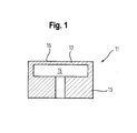
- a measuring device shown which is used in a combined pressure and temperature sensor, comprises a sensor element 11 with a rigid frame 13, in which a fluid chamber 15 is formed.
- a fluid to be measured in particular a liquid and / or a gas, located in the fluid chamber 15.
- the other side of the membrane 17, which faces away from the fluid is exposed to a reference pressure, in particular the ambient pressure or hydrostatic pressure of the atmosphere surrounding the sensor.
- the membrane 17 may be formed integrally or separately from the frame 13.
- the sensor element 11 has on the side facing away from the fluid chamber 15 of the membrane 17 on a flat surface 19 on which thin layers are deposited, as explained in more detail below.
- the measuring device is housed in a housing, not shown, which in the direction of an open side of the fluid chamber 15 has a functional connection has, for example, a thread with which the sensor can be coupled to a fluid housing, not shown.
- the membrane 17 is mechanically deflected or deformed.
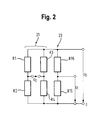
- U 0 is the supply voltage of the measuring bridge 21.
- the measuring bridge 21, together with the sensor element 11, forms a pressure transducer.
- the resistance elements R1-R4 are pressure-dependent resistance elements, ie a change in the fluid pressure leads to a corresponding change in the resistance value of the respective resistance element R1-R4.
- the resistance elements R1-R4 are each designed as strain gauges and applied in thin-film technology, in particular by means of PVD and / or CVD, on the flat surface 19 of the sensor element 11, in particular on the membrane 17.
- the resistive elements R1-R4 were applied with a single, common deposition, ie they are all made of the same material, which furthermore has no temperature dependence, for example titanium oxynitride.
- the resistance elements R1-R4 are in particular so shaped and / or arranged on the membrane 17, that with increasing pressure difference across the membrane 17, the electrical resistance of the two in the equivalent circuit of the measuring bridge 21 diagonally opposite resistance elements R1 and R4, for example, decreases, while the electrical resistance of the two in the equivalent circuit of the measuring bridge 21 diagonally opposite resistance elements R2 and R3 increases, or vice versa. In principle, however, it is sufficient if only one, two or three of the resistance elements R1-R4 are pressure-dependent. Non-pressure dependent resistive elements may e.g. be generated by appropriate geometric shape or arrangement or by separate deposition with another material.
- the measuring bridge 23 forms, together with the sensor element 11, a temperature transducer which operates independently of the pressure transducer.
- the further resistance element R15 is temperature-dependent.
- the further resistive element R15 was applied to the sensor element 11 by means of a further deposition separate from the abovementioned deposition and consists of a temperature-dependent material which is different from the material of the resistive elements R1-R4, for example of a nickel layer.
- the further resistance element R15 already has no pressure dependence due to the material used for this purpose and, moreover, is not applied on the membrane 17 but on its outside, on the frame 13 which is not subject to deformation.
- the further resistance element R 16 has already been applied to the membrane 17 together with the resistance elements R 1 -R 4, i. the further resistive element R16 is made of the same material as the resistive elements R1-R4 and is temperature independent.
- the shape and arrangement of the further resistance element R16 is chosen such that it - in contrast to the resistance elements R1-R4 - has no pressure dependence.
- the resistance elements R1-R4 and R16 can basically also be deposited only after the resistance element R15.
- At least two layers are deposited in succession for the pressure measurement and for the temperature measurement, each of which is patterned, for example by means of photolithographic processes, in such a way that electrical resistances are formed and interconnected, which are separate pressure- or temperature-dependent.
- the individual layers each have, in particular, a thickness or height of at most 3 ⁇ m, preferably at most 1 ⁇ m, and an electrical resistance in the range from 0.1 kohm to 50 kohm, preferably in the range from 0.5 kohm to 10 kohm, per resistor on.
- Such a layer may in each case also be a multi-layer, in which case at least one layer is formed as a functional layer.
- the layers for the pressure measurement and the temperature measurement are different from each other in at least one layer in their material composition.
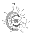
- Fig. 3 the two measuring bridges 21, 23 are shown according to an exemplary layout or in a plan view.
- the circular extent of the membrane 17, which is circular in the case shown, is shown by dashed lines.
- the resistance elements R1-R4, R15 and R16 of the two measuring bridges 21, 23 are provided for electrical contacting with terminals in the form of bonding pads 25.
- the terminals 25 were deposited together with the further resistance element R 15.
- the present invention describes the integration of a pressure transducer and a temperature transmitter, both of which are manufactured in the same technology, namely thin-film technology. This allows an overall cost-effective production.
Abstract
Description
- Die vorliegende Erfindung betrifft eine Messvorrichtung zur Messung eines Fluiddrucks und einer Temperatur des Fluids.
- Eine derartige kombinierte Messvorrichtung ist beispielsweise aus dem Dokument
DE 10 2010 012 823 A1 bekannt. Dort ist ein Druckmessumformer mit einem Gehäuse und wenigstens einer in dem Gehäuse ausgebildeten Bohrung offenbart, in die ein Thermoelement bestehend aus einem Gehäuse, einem Rohr und einem Temperatursensor eingesetzt ist. Die Produktion einer solchen Messvorrichtung ist jedoch relativ aufwendig und daher kostenintensiv. - Der vorliegenden Erfindung liegt die Aufgabe zugrunde, eine Messvorrichtung der eingangs genannten Art zu schaffen, die kostengünstig herstellbar ist.
- Diese Aufgabe wird durch eine Messvorrichtung mit den Merkmalen des Anspruchs 1 gelöst und insbesondere dadurch, dass für beide Messungen ein gemeinsames, eine Fluidkammer und eine Membran aufweisendes Sensorelement vorgesehen ist, auf das auf der der Fluidkammer abgewandten Seite der Membran sowohl eine der Druckmessung zugeordnete Widerstands-Messbrücke mit wenigstens einem druckabhängigen Widerstandselement zur Erzeugung einer dem Fluiddruck proportionalen Brückenspannung als auch eine der Temperaturmessung zugeordnete Widerstands-Messbrücke mit wenigstens einem temperaturabhängigen Widerstandselement zur Erzeugung einer der Fluidtemperatur proportionalen Brückenspannung jeweils in Dünnschichttechnologie aufgebracht sind.
- Die vorliegende Erfindung schafft demgemäß einen Druckmessumformer, der als Dünnschicht- bzw. Dünnfilmsensor ausgeführt ist, sowie einen in gleicher Technologie integriert hergestellten Temperaturmessumformer, wobei beide Messumformer in bzw. auf einem Sensorelement integriert sind. Die Herstellung der Messumformer für Druck und Temperatur erfolgt jeweils in Dünnschicht- bzw. Dünnfilmtechnologie, d.h. mittels physikalischer Gasphasenabscheidung (PVD) und/oder chemischer Gasphasenabscheidung (CVD). Erfindungsgemäß können also die Widerstandselemente des Druckmessumformers mit den Widerstandselementen des Temperaturmessumformers auf einem Dünnschicht-Sensorelement integriert werden, so dass letztlich nur ein einziger und/oder kombinierter Messumformer vorliegt. Hierdurch wird eine kostengünstige Herstellung der Messvorrichtung ermöglicht.
- Die der Druckmessung zugeordnete Widerstands-Messbrücke ist bevorzugt als Wheatstone'sche Messbrücke, insbesondere als Vollbrücke mit vier Widerstandselementen oder als Halbbrücke mit zwei Widerstandselementen, ausgebildet, um die dem Fluiddruck proportionale Brückenspannung, d.h. ein druckabhängiges Spannungssignal zu erzeugen. Die der Temperaturmessung zugeordnete, insbesondere von der der Druckmessung zugeordneten Widerstands-Messbrücke separat ausgebildete Widerstands-Messbrücke ist bevorzugt ebenfalls als Wheatstone'sche Messbrücke, insbesondere als Voll- oder Halbbrücke, ausgebildet, um die der Fluidtemperatur proportionale Brückenspannung, d.h. ein temperaturabhängiges Spannungssignal zu erzeugen. Vorzugsweise ist dem Sensorelement eine Verarbeitungs- und/oder Auswerteeinheit, insbesondere in Form einer Elektronik, nachgeschaltet, durch die die Signale der beiden Messbrücken verstärkt, linearisiert und/oder anderweitig weiter verarbeitet werden können. Insbesondere umfasst die jeweilige Messbrücke zum Abgreifen der jeweiligen Brückenspannung einen jeweiligen, insbesondere eigenen Messabgriff.
- Bevorzugt ist es, wenn die der Druckmessung zugeordneten Widerstandselemente temperaturunabhängig sind, und/oder die der Temperaturmessung zugeordneten Widerstandselemente druckunabhängig sind, wobei an dieser Stelle und nachstehend unter temperaturunabhängig bzw. druckunabhängig auch zumindest im Wesentlichen temperaturunabhängig bzw. druckunabhängig verstanden werden soll. Hierdurch wird erreicht, dass das jeweilige Spannungssignal von der jeweils anderen Messgröße nicht beeinflusst wird, wodurch die Auswertung des jeweiligen Spannungssignals vereinfacht wird. Grundsätzlich kann ein Temperaturabgleich der der Druckmessung zugeordneten Widerstands-Messbrücke, sofern sie eine Temperaturabhängigkeit aufweist, aber beispielsweise auch durch weitere, mit der Widerstands-Messbrücke verschaltete Widerstände erfolgen.
- Vorzugsweise umfasst die der Temperaturmessung zugeordnete Widerstands-Messbrücke wenigstens ein temperaturunabhängiges Widerstandselement. Insbesondere weist ein temperaturunabhängiges Widerstandselement keine oder im Verhältnis zu einem temperaturabhängigen Widerstandselement eine wesentlich geringere Temperaturabhängigkeit auf. Hierdurch kann die Auswertung des Spannungssignals der der Temperaturmessung zugeordneten Widerstands-Messbrücke vereinfacht werden.
- Insbesondere für den Fall, dass sie als Halbbrücke ausgebildet ist, kann die der Temperaturmessung zugeordnete Widerstands-Messbrücke genau ein temperaturabhängiges und/oder genau ein temperaturunabhängiges Widerstandselement umfassen.
- Bevorzugt sind die der Druckmessung zugeordneten Widerstandselemente und das vorgenannte, wenigstens eine der Temperaturmessung zugeordnete temperaturunabhängige Widerstandselement aus demselben Material gefertigt, und/oder sind das wenigstens eine der Temperaturmessung zugeordnete temperaturabhängige Widerstandselement und Anschlüsse für die beiden Widerstands-Messbrücken aus demselben Material gefertigt. Hierdurch wird ermöglicht, die beiden Messbrücken und deren Anschlüsse für eine elektrische Kontaktierung, insbesondere Bondpads, mit lediglich zwei Abscheidevorgängen aufzubringen.
- Vorzugsweise wird die Geometrie des vorgenannten, wenigstens einen der Temperaturmessung zugeordneten temperaturunabhängigen Widerstandselements derart gewählt, dass es keine Druckabhängigkeit aufweist.
- Insbesondere können die der Druckmessung zugeordneten Widerstandselemente und/ oder das vorgenannte, wenigstens eine der Temperaturmessung zugeordnete temperaturunabhängige Widerstandselement aus einem ersten Material gefertigt sein, und das wenigstens eine der Temperaturmessung zugeordnete temperaturabhängige Widerstandselement und/oder Anschlüsse für die beiden Widerstands-Messbrücken aus einem zweiten, von dem ersten Material verschiedenen Material gefertigt sein.
- Die Aufbringung der der Druckmessung zugeordneten Widerstandselemente und/ oder wenigstens eines der Temperaturmessung zugeordneten temperaturunabhängigen Widerstandselements kann in einer ersten Gasphasenabscheidung erfolgen, und die Aufbringung des wenigstens einen der Temperaturmessung zugeordneten temperaturabhängigen Widerstandselements und/oder von Anschlüssen für die beiden Widerstands-Mess-brücken in einer zweiten Gasphasenabscheidung.
- Bei dem Material der der Druckmessung zugeordneten Widerstandselemente und dem vorgenannten, wenigstens einen der Temperaturmessung zugeordneten temperaturunabhängigen Widerstandselement handelt es sich bevorzugt um ein Material, dessen elektrischer Widerstand durch Deformation stark veränderlich ist, aber keine oder nur eine geringe Temperaturempfindlichkeit aufweist, beispielsweise Titanoxinitrid. Bei dem Material des wenigstens einen der Temperaturmessung zugeordneten temperaturabhängigen Widerstandselements und der Anschlüsse für die beiden Widerstands-Messbrücken handelt es sich bevorzugt um ein Material, dessen elektrischer Widerstand deutlich temperaturabhängig ist, beispielsweise Nickel.
- Nach einer Ausbildung der Erfindung sind die der Druckmessung zugeordneten Widerstandselemente und/oder das vorgenannte, wenigstens eine der Temperaturmessung zugeordnete temperaturunabhängige Widerstandselement auf der Membran aufgebracht, und/oder ist das wenigstens eine der Temperaturmessung zugeordnete temperaturabhängige Widerstandselement zumindest teilweise auf einem insbesondere starren, die Membran an deren Peripherie abstützenden Rahmen oder Grundkörper aufgebracht. Sofern das Material des wenigstens einen der Temperaturmessung zugeordneten temperaturabhängigen Widerstandselements grundsätzlich eine Druckabhängigkeit aufweist, kann hierdurch eine Druckabhängigkeit des wenigstens einen der Temperaturmessung zugeordneten temperaturabhängigen Widerstandselements trotzdem verhindert werden.
- Insbesondere sind die der Druckmessung zugeordneten Widerstände und die der Temperaturmessung zugeordneten Widerstände in und/oder auf dem Sensorelement integriert sind.
- Insbesondere sind die der Druckmessung zugeordneten Widerstände und die der Temperaturmessung zugeordneten Widerstände auf einer für alle Widerstände gemeinsamen, durch die Membran und einen die Membran an deren Peripherie abstützenden Rahmen gebildeten ebenen Oberfläche des Sensorelements angeordnet.
- Bevorzugt sind der oder die druckabhängigen Widerstandselemente der der Druckmessung zugeordneten Widerstands-Messbrücke jeweils als bzw. wie ein Dehnungsmessstreifen oder nach Art eines Dehnungsmessstreifens ausgebildet. Die Druckabhängigkeit des oder der druckabhängigen Widerstandselemente kann beispielsweise auf einer Änderung des Widerstands durch eine Längen- und Querschnittsänderung der Dehnungsmessstreifen oder auf einer Änderung des Widerstands durch einen piezoresistiven Effekt basieren.
- Nach einer anderen Ausbildung der Erfindung sind die beiden Messbrücken derart ausgebildet, dass sie voneinander unabhängig den Messgrößen Druck und Temperatur proportionale Spannungssignale erzeugen. Ein Defekt der einen Messbrücke beeinträchtigt daher nicht die Funktion der anderen Messbrücke. Insbesondere sind die beiden Messbrücken parallel zueinander geschaltet.
- Nach einer weiteren Ausbildung der Erfindung sind die beiden Messbrücken derart ausgebildet, dass sie eine gemeinsame Spannungsversorgung und/oder wenigstens einen gemeinsamen Anschluss aufweisen. Hierdurch können Synergien genutzt werden.
- Die Erfindung betrifft ferner ein Verfahren zur Herstellung einer Messvorrichtung zur Messung eines Fluiddrucks und zur Messung einer Temperatur des Fluids, insbesondere einer Messvorrichtung, wie sie vorstehend beschrieben ist, wobei auf einem für beide Messungen gemeinsamen, eine Fluidkammer und eine Membran aufweisenden Sensorelement nacheinander auf der der Fluidkammer abgewandten Seite der Membran wenigstens ein einer Widerstands-Messbrücke der Druckmessung zugeordnetes druckabhängiges Widerstandselement zur Erzeugung einer dem Fluiddruck proportionalen Brückenspannung und wenigstens ein einer Widerstands-Messbrücke der Temperaturmessung zugeordnetes temperaturabhängiges Widerstandselement zur Erzeugung einer der Fluidtemperatur proportionalen Brückenspannung jeweils mittels einer Gasphasenabscheidung aufgebracht werden.
- Grundsätzlich ist es möglich, dass die Widerstandselemente der beiden Messbrücken mit lediglich zwei oder mit mehr als lediglich zwei Abscheidevorgängen auf das Sensorelement aufgebracht werden. Beispielsweise können mit einer ersten Abscheidung lediglich druckabhängige Widerstandselemente, mit einer zweiten Abscheidung lediglich temperaturabhängige Widerstandselemente und mit einer dritten Abscheidung sowohl druck- als auch temperaturunabhängige Widerstandselemente aufgebracht werden, wobei die Reihenfolge der Abscheidungen grundsätzlich beliebig gewählt werden kann.
- Vorteilhafte Ausführungsformen des Verfahrens ergeben sich in analoger Weise aus den Weiterbildungen der erfindungsgemäßen Messvorrichtung.
- Weitere vorteilhafte Ausführungsformen der Erfindung sind auch in den Unteransprüchen, der Figurenbeschreibung und der Zeichnung angegeben.
- Die Erfindung wird im Folgenden beispielhaft unter Bezugnahme auf die Zeichnung beschrieben. Es zeigen,
- Fig. 1
- eine schematische Darstellung eines Längsschnitts durch eine erfindungsgemäße kombinierte Druck- und Temperaturmessvorrichtung,
- Fig. 2
- ein Schaltbild zweier Messbrücken der erfindungsgemäßen Messvorrichtung aus
Fig. 1 , und - Fig. 3
- ein Layout der beiden Messbrücken aus
Fig. 2 gemäß einer erfindungsgemäßen Ausführungsform. - Die in
Fig. 1 gezeigte Messvorrichtung, die in einen kombinierten Druck- und Temperatursensor eingesetzt ist, umfasst ein Sensorelement 11 mit einem starren Rahmen 13, in dem eine Fluidkammer 15 ausgebildet ist. Zur Messung eines Fluiddrucks wird eine Seite einer an ihrer Peripherie an dem Rahmen 13 abgestützten Membran 17 des Sensorelements 11 mit einem in der Fluidkammer 15 befindlichen, zu messenden Fluid, insbesondere einer Flüssigkeit und/oder einem Gas, beaufschlagt. Die andere Seite der Membran 17, die dem Fluid abgewandt ist, ist einem Referenzdruck, insbesondere dem Umgebungsdruck bzw. hydrostatischen Druck der den Sensor umgebenden Atmosphäre, ausgesetzt. Die Membran 17 kann einstückig oder separat von dem Rahmen 13 ausgebildet sein. Das Sensorelement 11 weist auf der der Fluidkammer 15 abgewandten Seite der Membran 17 eine ebene Oberfläche 19 auf, auf der dünne Schichten abgeschieden sind, wie nachstehend näher erläutert ist. Die Messvorrichtung ist in einem nicht dargestellten Gehäuse untergebracht, das in Richtung einer offenen Seite der Fluidkammer 15 einen funktionalen Anschluss aufweist, beispielsweise ein Gewinde, mit dem der Sensor an ein nicht gezeigtes Fluidgehäuse gekoppelt werden kann. - Bei einer Druckdifferenz zwischen ihren beiden Seiten wird die Membran 17 mechanisch ausgelenkt bzw. deformiert. Diese Deformation wird gemäß
Fig. 2 durch vier elektrische Widerstandselemente R1-R4 einer Wheatstone'schen Widerstands-Messbrücke 21, die auf der der Fluidkammer 15 abgewandten Seite der Membran 17 aufgebracht sind, erfasst und in Form einer Brückenspannung
ausgegeben, wobei in an sich bekannter Weise aus dem Wert der Brückenspannung UD auf den anliegenden Fluiddruck rückgeschlossen werden kann. Bei U 0 handelt es sich um die Versorgungsspannung der Messbrücke 21. Die Messbrücke 21 bildet zusammen mit dem Sensorelement 11 einen Druckmessumformer. - Bei den Widerstandselementen R1-R4 handelt es sich um druckabhängige Widerstandselemente, d.h. eine Änderung des Fluiddrucks führt zu einer entsprechenden Änderung des Widerstandswert des jeweiligen Widerstandselements R1-R4. Die Widerstandselemente R1-R4 sind jeweils als Dehnungsmessstreifen ausgebildet und in Dünnschichttechnologie, insbesondere mittels PVD und/oder CVD, auf der ebenen Oberfläche 19 des Sensorelements 11, insbesondere auf der Membran 17, aufgebracht. Die Widerstandselemente R1-R4 wurden mit einer einzigen, gemeinsamen Abscheidung aufgebracht, d.h. sie bestehen alle aus demselben Material, das darüber hinaus keine Temperaturabhängigkeit aufweist, beispielsweise Titanoxinitrid.
- Die Widerstandselemente R1-R4 sind dabei insbesondere derart geformt und/oder auf der Membran 17 angeordnet, dass mit steigender Druckdifferenz an der Membran 17 der elektrische Widerstand der beiden im Ersatzschaltbild der Messbrücke 21 diagonal gegenüberliegenden Widerstandselemente R1 und R4 beispielsweise abnimmt, während der elektrische Widerstand der beiden im Ersatzschaltbild der Messbrücke 21 diagonal gegenüberliegenden Widerstandselemente R2 und R3 zunimmt, oder umgekehrt. Grundsätzlich ist es jedoch ausreichend, wenn lediglich ein, zwei oder drei der Widerstandselemente R1-R4 druckabhängig sind. Nichtdruckabhängige Widerstandselemente können z.B. durch entsprechende geometrische Formgebung oder Anordnung oder durch separate Abscheidung mit einem anderen Material erzeugt werden.
- Darüber hinaus sind auf der ebenen Oberfläche 19 des Sensorelements 11 zwei weitere elektrische Widerstandselemente R 15 und R 16 einer weiteren Widerstands-Messbrücke 23, die parallel zu der Messbrücke 21 geschaltet ist, in Dünnschichttechnologie aufgebracht, mit der eine weitere Brückenspannung

erzeugt werden kann, wobei in an sich bekannter Weise aus dem Wert der weiteren Brückenspannung UT auf die Temperatur des anliegenden Fluids rückgeschlossen werden kann. Die Messbrücke 23 bildet zusammen mit dem Sensorelement 11 einen Temperaturmessumformer, der unabhängig von dem Druckmessumformer arbeitet. - Hierzu ist das weitere Widerstandselement R15 temperaturabhängig ausgebildet. Das weitere Widerstandselement R15 wurde mittels einer weiteren, von der vorgenannten Abscheidung separaten Abscheidung auf das Sensorelement 11 aufgebracht und besteht aus einem temperaturabhängigen Material, das von dem Material der Widerstandselemente R1-R4 verschieden ist, beispielsweise aus einer Nickel-Schicht. Das weitere Widerstandselement R15 weist bereits aufgrund des hierfür verwendeten Materials keine Druckabhängigkeit auf und ist darüber hinaus nicht auf der Membran 17, sondern außerhalb hiervon, auf dem Rahmen 13, der keiner Deformation unterworfen ist, aufgebracht.
- Das weitere Widerstandselement R 16 hingegen wurde bereits zusammen mit den Widerstandselementen R1-R4 auf die Membran 17 aufgebracht, d.h. das weitere Widerstandselement R16 besteht aus demselben Material wie die Widerstandselemente R1-R4 und ist temperaturunabhängig. Die Form und Anordnung des weiteren Widerstandselements R16 ist dabei derart gewählt, dass es - im Gegensatz zu den Widerstandselementen R1-R4 - keine Druckabhängigkeit aufweist. Die Widerstandselemente R1-R4 und R 16 können grundsätzlich auch erst nach dem Widerstandselement R 15 abgeschieden werden.
- Bei der Herstellung der beschriebenen Messvorrichtung werden also nacheinander wenigstens zwei Schichten für die Druckmessung und für die Temperaturmessung abgeschieden, die jeweils beispielsweise mittels fotolithographischer Verfahren derart strukturiert werden, dass elektrische Widerstände gebildet und verschaltet werden, die getrennt druck- bzw. temperaturabhängig sind. Die einzelnen Schichten weisen jeweils insbesondere eine Dicke bzw. Höhe von höchstens 3 µm, bevorzugt höchstens 1 µm, und einen elektrischen Widerstand im Bereich von 0,1 kOhm bis 50 kohm, bevorzugt im Bereich von 0,5 kohm bis 10 kohm, pro Widerstand auf. Bei einer derartigen Schicht kann es sich jeweils auch um eine Mehrlagenschicht handeln, wobei dann wenigstens eine Lage als funktionale Lage ausgebildet ist. Die Schichten für die Druckmessung und die Temperaturmessung sind dabei in mindestens einer Lage in ihrer stofflichen Zusammensetzung voneinander verschieden.
- In
Fig. 3 sind die beiden Messbrücken 21, 23 gemäß einem beispielhaften Layout bzw. in einer Draufsicht gezeigt. Die in dem gezeigten Fall kreisrunde Erstreckung der Membran 17 ist strichliniert dargestellt. Wie ausFig. 3 ersichtlich ist, sind die Widerstandselemente R1-R4, R15 und R16 der beiden Messbrücken 21, 23 zur elektrischen Kontaktierung mit Anschlüssen in Form von Bondpads 25 versehen. Die Anschlüsse 25 wurden zusammen mit dem weiteren Widerstandselement R 15 abgeschieden. - Die vorliegende Erfindung beschreibt die Integration eines Messumformers für Druck und eines Messumformers für Temperatur, die beide in derselben Technologie, nämlich der Dünnschichttechnologie, hergestellt sind. Dies ermöglicht eine insgesamt kostengünstige Herstellung.
-
- 11
- Sensorelement
- 13
- Rahmen
- 15
- Fluidkammer
- 17
- Membran
- 19
- Oberfläche
- 21
- Messbrücke
- 23
- weitere Messbrücke
- 25
- Bondpad
- R1
- Widerstandselement
- R2
- Widerstandselement
- R3
- Widerstandselement
- R4
- Widerstandselement
- R15
- weiteres Widerstandselement
- R16
- weiteres Widerstandselement
- U0
- Versorgungsspannung
- UD
- Brückenspannung
- UT
- weitere Brückenspannung
Claims (12)
- Messvorrichtung zur Messung eines Fluiddrucks und einer Temperatur des Fluids,
dadurch gekennzeichnet,
dass für beide Messungen ein gemeinsames, eine Fluidkammer (15) und eine Membran (17) aufweisendes Sensorelement (11) vorgesehen ist, auf das auf der der Fluidkammer (15) abgewandten Seite der Membran (17) sowohl eine der Druckmessung zugeordnete Widerstands-Messbrücke (21) mit wenigstens einem druckabhängigen Widerstandselement (R1-R4) zur Erzeugung einer dem Fluiddruck proportionalen Brückenspannung (UD) als auch eine der Temperaturmessung zugeordnete Widerstands-Messbrücke (23) mit wenigstens einem temperaturabhängigen Widerstandselement (R 15) zur Erzeugung einer der Fluidtemperatur proportionalen Brückenspannung (UT) jeweils in Dünnschichttechnologie aufgebracht sind. - Messvorrichtung nach Anspruch 1,
dadurch gekennzeichnet,
dass die der Druckmessung zugeordneten Widerstandselemente (R1-R4) temperaturunabhängig sind, und/oder dass die der Temperaturmessung zugeordneten Widerstandselemente (R15, R16) druckunabhängig sind. - Messvorrichtung nach Anspruch 1 oder 2,
dadurch gekennzeichnet,
dass die der Temperaturmessung zugeordnete Widerstands-Messbrücke (23) wenigstens ein temperaturunabhängiges Widerstandselement (R16) umfasst. - Messvorrichtung nach zumindest einem der vorstehenden Ansprüche,
dadurch gekennzeichnet,
dass die der Druckmessung zugeordneten Widerstandselemente (R1-R4) und wenigstens ein der Temperaturmessung zugeordnetes temperaturunabhängiges Widerstandselement (R16) aus demselben Material gefertigt sind, und/oder dass das wenigstens eine der Temperaturmessung zugeordnete temperaturabhängige Widerstandselement (R 15) und Anschlüsse (25) für die beiden Widerstands-Messbrücken (21, 23) aus demselben Material gefertigt sind. - Messvorrichtung nach zumindest einem der vorstehenden Ansprüche,
dadurch gekennzeichnet,
dass die der Druckmessung zugeordneten Widerstandselemente (R1-R4) und/oder wenigstens ein der Temperaturmessung zugeordnetes temperaturunabhängiges Widerstandselement (R16) aus einem ersten Material gefertigt sind, und das wenigstens eine der Temperaturmessung zugeordnete temperaturabhängige Widerstandselement (R15) und/oder Anschlüsse (25) für die beiden Widerstands-Messbrücken (21, 23) aus einem zweiten, von dem ersten Material verschiedenen Material gefertigt ist. - Messvorrichtung nach zumindest einem der vorstehenden Ansprüche,
dadurch gekennzeichnet,
dass die Aufbringung der der Druckmessung zugeordneten Widerstandselemente (R1-R4) und/oder wenigstens eines der Temperaturmessung zugeordneten temperaturunabhängigen Widerstandselements (R16) in einer ersten Gasphasenabscheidung erfolgt, und die Aufbringung des wenigstens einen der Temperaturmessung zugeordneten temperaturabhängigen Widerstandselements (R 15) und/oder von Anschlüssen (25) für die beiden Widerstands-Messbrücken (21, 23) in einer zweiten Gasphasenabscheidung erfolgt. - Messvorrichtung nach zumindest einem der vorstehenden Ansprüche,
dadurch gekennzeichnet,
dass die der Druckmessung zugeordneten Widerstandselemente (R1-R4) und/oder wenigstens ein der Temperaturmessung zugeordnetes temperaturunabhängiges Widerstandselement (R16) auf der Membran (17) aufgebracht sind, und/oder dass das wenigstens eine der Temperaturmessung zugeordnete temperaturabhängige Widerstandselement (R15) zumindest teilweise auf einem die Membran (17) an deren Peripherie abstützenden Rahmen (13) aufgebracht ist. - Messvorrichtung nach zumindest einem der vorstehenden Ansprüche,
dadurch gekennzeichnet,
dass die der Druckmessung zugeordneten Widerstände (R1-R4) und die der Temperaturmessung zugeordneten Widerstände (R 15, R16) in und/oder auf dem Sensorelement (11) integriert sind. - Messvorrichtung nach zumindest einem der vorstehenden Ansprüche,
dadurch gekennzeichnet,
dass der oder die druckabhängigen Widerstandselemente (R1-R4) der der Druckmessung zugeordneten Widerstands-Messbrücke (21) jeweils als ein Dehnungsmessstreifen ausgebildet sind. - Messvorrichtung nach zumindest einem der vorstehenden Ansprüche,
dadurch gekennzeichnet,
dass die beiden Messbrücken (21, 23) derart ausgebildet sind, dass sie voneinander unabhängig den Messgrößen Druck und Temperatur proportionale Spannungssignale (UD, UT) erzeugen. - Messvorrichtung nach zumindest einem der vorstehenden Ansprüche,
dadurch gekennzeichnet,
dass die beiden Messbrücken (21, 23) derart ausgebildet sind, dass sie eine gemeinsame Spannungsversorgung (Uo) und/oder wenigstens einen gemeinsamen Anschluss (25) aufweisen. - Verfahren zur Herstellung einer Messvorrichtung zur Messung eines Fluiddrucks und zur Messung einer Temperatur des Fluids, insbesondere nach einem der vorhergehenden Ansprüche,
dadurch gekennzeichnet,
dass auf einem für beide Messungen gemeinsamen, eine Fluidkammer und eine Membran aufweisenden Sensorelement nacheinander auf der der Fluidkammer abgewandten Seite der Membran wenigstens ein einer Widerstands-Messbrücke der Druckmessung zugeordnetes druckabhängiges Widerstandselement zur Erzeugung einer dem Fluiddruck proportionalen Brückenspannung (UD) und wenigstens ein einer Widerstands-Messbrücke der Temperaturmessung zugeordnetes temperaturabhängiges Widerstandselement zur Erzeugung einer der Fluidtemperatur proportionalen Brückenspannung (UT) jeweils mittels einer Gasphasenabscheidung aufgebracht werden.
Applications Claiming Priority (1)
| Application Number | Priority Date | Filing Date | Title |
|---|---|---|---|
| DE102011109461A DE102011109461A1 (de) | 2011-08-04 | 2011-08-04 | Druck- und Temperaturmessvorrichtung |
Publications (4)
| Publication Number | Publication Date |
|---|---|
| EP2554964A2 true EP2554964A2 (de) | 2013-02-06 |
| EP2554964A3 EP2554964A3 (de) | 2014-10-01 |
| EP2554964B1 EP2554964B1 (de) | 2016-04-13 |
| EP2554964B2 EP2554964B2 (de) | 2021-03-10 |
Family
ID=46506212
Family Applications (1)
| Application Number | Title | Priority Date | Filing Date |
|---|---|---|---|
| EP12175538.3A Active EP2554964B2 (de) | 2011-08-04 | 2012-07-09 | Druck- und Temperaturmessvorrichtung |
Country Status (2)
| Country | Link |
|---|---|
| EP (1) | EP2554964B2 (de) |
| DE (1) | DE102011109461A1 (de) |
Cited By (3)
| Publication number | Priority date | Publication date | Assignee | Title |
|---|---|---|---|---|
| CN104819798A (zh) * | 2015-05-08 | 2015-08-05 | 西南科技大学 | 一种在线监测尾矿淋滤实验水压变化传感器 |
| DE102018106518A1 (de) * | 2018-03-20 | 2019-09-26 | Tdk Electronics Ag | Sensorelement zur Druck- und Temperaturmessung |
| CN113360025A (zh) * | 2021-06-23 | 2021-09-07 | 维沃移动通信有限公司 | 电子设备 |
Families Citing this family (1)
| Publication number | Priority date | Publication date | Assignee | Title |
|---|---|---|---|---|
| DE102018121294A1 (de) * | 2018-08-31 | 2020-03-05 | Trafag Ag | Verfahren zur Herstellung eines Sensorelements mit mehreren Funktionsschichten für einen Drucksensor, Sensorelement und Sensor |
Citations (1)
| Publication number | Priority date | Publication date | Assignee | Title |
|---|---|---|---|---|
| DE102010012823A1 (de) | 2009-12-11 | 2011-06-16 | Armaturenbau Gmbh | Druckmittler mit Temperatursensor |
Family Cites Families (16)
| Publication number | Priority date | Publication date | Assignee | Title |
|---|---|---|---|---|
| US2738678A (en) * | 1952-10-21 | 1956-03-20 | Leeds & Northrup Co | Liquid manometers |
| US4320664A (en) | 1980-02-25 | 1982-03-23 | Texas Instruments Incorporated | Thermally compensated silicon pressure sensor |
| DE9209083U1 (de) * | 1991-07-20 | 1992-09-24 | Tubbesing, Dietmar, Dipl.-Ing., 5760 Arnsberg, De | |
| US5343755A (en) * | 1993-05-05 | 1994-09-06 | Rosemount Inc. | Strain gage sensor with integral temperature signal |
| DE4415984A1 (de) * | 1994-05-06 | 1995-11-09 | Bosch Gmbh Robert | Halbleitersensor mit Schutzschicht |
| SE9600334D0 (sv) * | 1996-01-30 | 1996-01-30 | Radi Medical Systems | Combined flow, pressure and temperature sensor |
| JP3107516B2 (ja) * | 1996-05-01 | 2000-11-13 | 株式会社日立製作所 | 複合センサ |
| JPH10170370A (ja) * | 1996-12-10 | 1998-06-26 | Nok Corp | 圧力センサ |
| US6612175B1 (en) * | 2000-07-20 | 2003-09-02 | Nt International, Inc. | Sensor usable in ultra pure and highly corrosive environments |
| GB2370122B (en) | 2000-12-16 | 2005-04-27 | Senstronics Ltd | Temperature compensated strain gauge |
| EP1281947A1 (de) | 2001-08-03 | 2003-02-05 | Trafag AG | Hochdrucksensor und Verfahren zur Herstellung eines Hochdrucksensors |
| DE10304024B4 (de) * | 2002-02-15 | 2015-08-20 | Continental Teves Ag & Co. Ohg | Verfahren und Schaltungsanordnung zur Überprüfung einer Drucksensoranordnung |
| DE102005015335A1 (de) * | 2005-04-01 | 2006-10-05 | Suss Microtec Test Systems Gmbh | Druckprober zur partiellen, berührungslosen Druckmessung von Drucksensoren |
| DE102006007463B3 (de) * | 2006-02-17 | 2007-06-21 | Jumo Gmbh & Co. Kg | Brückenschaltung und Verfahren zum Abgleichen einer Brückenschaltung |
| DE102006047481B4 (de) * | 2006-04-26 | 2023-02-09 | Fritsch Gmbh | Planeten- oder Fliehkraftkugelmühle im Labormaßstab mit Druck- und Temperaturerfassung |
| JP2008039760A (ja) * | 2006-07-14 | 2008-02-21 | Denso Corp | 圧力センサ |
-
2011
- 2011-08-04 DE DE102011109461A patent/DE102011109461A1/de active Pending
-
2012
- 2012-07-09 EP EP12175538.3A patent/EP2554964B2/de active Active
Patent Citations (1)
| Publication number | Priority date | Publication date | Assignee | Title |
|---|---|---|---|---|
| DE102010012823A1 (de) | 2009-12-11 | 2011-06-16 | Armaturenbau Gmbh | Druckmittler mit Temperatursensor |
Cited By (7)
| Publication number | Priority date | Publication date | Assignee | Title |
|---|---|---|---|---|
| CN104819798A (zh) * | 2015-05-08 | 2015-08-05 | 西南科技大学 | 一种在线监测尾矿淋滤实验水压变化传感器 |
| DE102018106518A1 (de) * | 2018-03-20 | 2019-09-26 | Tdk Electronics Ag | Sensorelement zur Druck- und Temperaturmessung |
| WO2019180018A1 (de) * | 2018-03-20 | 2019-09-26 | Tdk Electronics Ag | Sensorelement zur druck- und temperaturmessung |
| CN111886486A (zh) * | 2018-03-20 | 2020-11-03 | Tdk电子股份有限公司 | 用于压力测量和温度测量的传感元件 |
| CN111886486B (zh) * | 2018-03-20 | 2022-04-08 | Tdk电子股份有限公司 | 用于压力测量和温度测量的传感元件 |
| CN113360025A (zh) * | 2021-06-23 | 2021-09-07 | 维沃移动通信有限公司 | 电子设备 |
| CN113360025B (zh) * | 2021-06-23 | 2023-08-22 | 维沃移动通信有限公司 | 电子设备 |
Also Published As
| Publication number | Publication date |
|---|---|
| EP2554964A3 (de) | 2014-10-01 |
| EP2554964B1 (de) | 2016-04-13 |
| EP2554964B2 (de) | 2021-03-10 |
| DE102011109461A1 (de) | 2013-02-07 |
Similar Documents
| Publication | Publication Date | Title |
|---|---|---|
| DE10256376B4 (de) | Massendurchflußmeßgerät und Verfahren zur Druckmessung bei einem Massendurchflußmeßgerät | |
| EP1640696B1 (de) | Drucksensor | |
| DE60025355T2 (de) | Dehnungsmessstreifen | |
| DE3703697A1 (de) | Drucksensor | |
| DE2608381B1 (de) | Messumformer | |
| DE102008040525A1 (de) | Mikromechanisches Sensorelement, Verfahren zur Herstellung eines mikromechanischen Sensorelements und Verfahren zum Betrieb eines mikromechanischen Sensorelements | |
| EP2554964B1 (de) | Druck- und Temperaturmessvorrichtung | |
| EP3047249A1 (de) | Druckmessumformer | |
| DE19754613A1 (de) | Drucksensor vom Dehnungsmesser-Typ | |
| DE102018203251B4 (de) | Messen von mechanischen Veränderungen | |
| DE112018008166T5 (de) | Mehrachsiger tastsensor | |
| DE102009024576B4 (de) | Differenzdrucksensor | |
| WO2009156209A1 (de) | Drucksensoranordnung | |
| DE10063070A1 (de) | Flußsensor des Wärmeerzeugungstyps | |
| EP3304019B1 (de) | Drucksensor mit einer aktivhartlötung | |
| DE102019102908A1 (de) | Sensorvorrichtung für Druckmessungen von Fluiden, System für Druckmessungen von Fluiden | |
| DE3042506C2 (de) | Dehnungsmeßstreifenwandler | |
| EP2543979A2 (de) | Druckmessumformer | |
| DE102006058269B4 (de) | Verfahren zur Kalibrierung mindestens eines Drucksensors und entsprechender Drucksensor | |
| DE102016218211A1 (de) | Drucksensor zur Erfassung eines Drucks eines fluiden Mediums in einem Messraum | |
| DE102008055774B4 (de) | Vorrichtung zum Messen einer Temperatur eines Bauteils und Vorrichtung zum Messen einer Dehnung eines Bauteils | |
| EP3935361B1 (de) | Verfahren zum betreiben einer drucksensoranordnung | |
| DE102013114424A1 (de) | Thermischer Durchflusssensor | |
| DE102011006922B4 (de) | Messwandler für die Sensortechnik | |
| DE102017223831A1 (de) | Dehnungsstreifen umfassend ein flexibles Substrat sowie eine Widerstandsschicht und Sensorelement umfassend einen Dehnungsmessstreifen |
Legal Events
| Date | Code | Title | Description |
|---|---|---|---|
| PUAI | Public reference made under article 153(3) epc to a published international application that has entered the european phase |
Free format text: ORIGINAL CODE: 0009012 |
|
| AK | Designated contracting states |
Kind code of ref document: A2 Designated state(s): AL AT BE BG CH CY CZ DE DK EE ES FI FR GB GR HR HU IE IS IT LI LT LU LV MC MK MT NL NO PL PT RO RS SE SI SK SM TR |
|
| AX | Request for extension of the european patent |
Extension state: BA ME |
|
| PUAL | Search report despatched |
Free format text: ORIGINAL CODE: 0009013 |
|
| AK | Designated contracting states |
Kind code of ref document: A3 Designated state(s): AL AT BE BG CH CY CZ DE DK EE ES FI FR GB GR HR HU IE IS IT LI LT LU LV MC MK MT NL NO PL PT RO RS SE SI SK SM TR |
|
| AX | Request for extension of the european patent |
Extension state: BA ME |
|
| RIC1 | Information provided on ipc code assigned before grant |
Ipc: G01L 19/00 20060101ALI20140825BHEP Ipc: G01L 9/00 20060101AFI20140825BHEP Ipc: G01L 19/04 20060101ALI20140825BHEP |
|
| 17P | Request for examination filed |
Effective date: 20150331 |
|
| RBV | Designated contracting states (corrected) |
Designated state(s): AL AT BE BG CH CY CZ DE DK EE ES FI FR GB GR HR HU IE IS IT LI LT LU LV MC MK MT NL NO PL PT RO RS SE SI SK SM TR |
|
| 17Q | First examination report despatched |
Effective date: 20150619 |
|
| REG | Reference to a national code |
Ref country code: DE Ref legal event code: R079 Ref document number: 502012006694 Country of ref document: DE Free format text: PREVIOUS MAIN CLASS: G01L0009000000 Ipc: G01K0007200000 |
|
| GRAP | Despatch of communication of intention to grant a patent |
Free format text: ORIGINAL CODE: EPIDOSNIGR1 |
|
| RIC1 | Information provided on ipc code assigned before grant |
Ipc: G01L 19/00 20060101ALI20151001BHEP Ipc: G01L 9/00 20060101ALI20151001BHEP Ipc: G01K 7/20 20060101AFI20151001BHEP |
|
| INTG | Intention to grant announced |
Effective date: 20151028 |
|
| GRAS | Grant fee paid |
Free format text: ORIGINAL CODE: EPIDOSNIGR3 |
|
| GRAA | (expected) grant |
Free format text: ORIGINAL CODE: 0009210 |
|
| STAA | Information on the status of an ep patent application or granted ep patent |
Free format text: STATUS: THE PATENT HAS BEEN GRANTED |
|
| AK | Designated contracting states |
Kind code of ref document: B1 Designated state(s): AL AT BE BG CH CY CZ DE DK EE ES FI FR GB GR HR HU IE IS IT LI LT LU LV MC MK MT NL NO PL PT RO RS SE SI SK SM TR |
|
| REG | Reference to a national code |
Ref country code: GB Ref legal event code: FG4D Free format text: NOT ENGLISH |
|
| REG | Reference to a national code |
Ref country code: AT Ref legal event code: REF Ref document number: 790637 Country of ref document: AT Kind code of ref document: T Effective date: 20160415 Ref country code: CH Ref legal event code: EP Ref country code: CH Ref legal event code: NV Representative=s name: INTELLECTUAL PROPERTY SERVICES GMBH, CH |
|
| REG | Reference to a national code |
Ref country code: IE Ref legal event code: FG4D Free format text: LANGUAGE OF EP DOCUMENT: GERMAN |
|
| REG | Reference to a national code |
Ref country code: DE Ref legal event code: R096 Ref document number: 502012006694 Country of ref document: DE |
|
| REG | Reference to a national code |
Ref country code: FR Ref legal event code: PLFP Year of fee payment: 5 |
|
| REG | Reference to a national code |
Ref country code: LT Ref legal event code: MG4D |
|
| REG | Reference to a national code |
Ref country code: NL Ref legal event code: MP Effective date: 20160413 |
|
| PG25 | Lapsed in a contracting state [announced via postgrant information from national office to epo] |
Ref country code: FI Free format text: LAPSE BECAUSE OF FAILURE TO SUBMIT A TRANSLATION OF THE DESCRIPTION OR TO PAY THE FEE WITHIN THE PRESCRIBED TIME-LIMIT Effective date: 20160413 Ref country code: NL Free format text: LAPSE BECAUSE OF FAILURE TO SUBMIT A TRANSLATION OF THE DESCRIPTION OR TO PAY THE FEE WITHIN THE PRESCRIBED TIME-LIMIT Effective date: 20160413 Ref country code: NO Free format text: LAPSE BECAUSE OF FAILURE TO SUBMIT A TRANSLATION OF THE DESCRIPTION OR TO PAY THE FEE WITHIN THE PRESCRIBED TIME-LIMIT Effective date: 20160713 Ref country code: PL Free format text: LAPSE BECAUSE OF FAILURE TO SUBMIT A TRANSLATION OF THE DESCRIPTION OR TO PAY THE FEE WITHIN THE PRESCRIBED TIME-LIMIT Effective date: 20160413 Ref country code: LT Free format text: LAPSE BECAUSE OF FAILURE TO SUBMIT A TRANSLATION OF THE DESCRIPTION OR TO PAY THE FEE WITHIN THE PRESCRIBED TIME-LIMIT Effective date: 20160413 |
|
| PGFP | Annual fee paid to national office [announced via postgrant information from national office to epo] |
Ref country code: CH Payment date: 20160721 Year of fee payment: 5 |
|
| PG25 | Lapsed in a contracting state [announced via postgrant information from national office to epo] |
Ref country code: SE Free format text: LAPSE BECAUSE OF FAILURE TO SUBMIT A TRANSLATION OF THE DESCRIPTION OR TO PAY THE FEE WITHIN THE PRESCRIBED TIME-LIMIT Effective date: 20160413 Ref country code: ES Free format text: LAPSE BECAUSE OF FAILURE TO SUBMIT A TRANSLATION OF THE DESCRIPTION OR TO PAY THE FEE WITHIN THE PRESCRIBED TIME-LIMIT Effective date: 20160413 Ref country code: RS Free format text: LAPSE BECAUSE OF FAILURE TO SUBMIT A TRANSLATION OF THE DESCRIPTION OR TO PAY THE FEE WITHIN THE PRESCRIBED TIME-LIMIT Effective date: 20160413 Ref country code: GR Free format text: LAPSE BECAUSE OF FAILURE TO SUBMIT A TRANSLATION OF THE DESCRIPTION OR TO PAY THE FEE WITHIN THE PRESCRIBED TIME-LIMIT Effective date: 20160714 Ref country code: LV Free format text: LAPSE BECAUSE OF FAILURE TO SUBMIT A TRANSLATION OF THE DESCRIPTION OR TO PAY THE FEE WITHIN THE PRESCRIBED TIME-LIMIT Effective date: 20160413 Ref country code: HR Free format text: LAPSE BECAUSE OF FAILURE TO SUBMIT A TRANSLATION OF THE DESCRIPTION OR TO PAY THE FEE WITHIN THE PRESCRIBED TIME-LIMIT Effective date: 20160413 Ref country code: PT Free format text: LAPSE BECAUSE OF FAILURE TO SUBMIT A TRANSLATION OF THE DESCRIPTION OR TO PAY THE FEE WITHIN THE PRESCRIBED TIME-LIMIT Effective date: 20160816 |
|
| PGFP | Annual fee paid to national office [announced via postgrant information from national office to epo] |
Ref country code: FR Payment date: 20160721 Year of fee payment: 5 |
|
| PG25 | Lapsed in a contracting state [announced via postgrant information from national office to epo] |
Ref country code: IT Free format text: LAPSE BECAUSE OF FAILURE TO SUBMIT A TRANSLATION OF THE DESCRIPTION OR TO PAY THE FEE WITHIN THE PRESCRIBED TIME-LIMIT Effective date: 20160413 Ref country code: BE Free format text: LAPSE BECAUSE OF NON-PAYMENT OF DUE FEES Effective date: 20160731 |
|
| REG | Reference to a national code |
Ref country code: DE Ref legal event code: R026 Ref document number: 502012006694 Country of ref document: DE |
|
| PLBI | Opposition filed |
Free format text: ORIGINAL CODE: 0009260 |
|
| PLBI | Opposition filed |
Free format text: ORIGINAL CODE: 0009260 |
|
| PG25 | Lapsed in a contracting state [announced via postgrant information from national office to epo] |
Ref country code: EE Free format text: LAPSE BECAUSE OF FAILURE TO SUBMIT A TRANSLATION OF THE DESCRIPTION OR TO PAY THE FEE WITHIN THE PRESCRIBED TIME-LIMIT Effective date: 20160413 Ref country code: RO Free format text: LAPSE BECAUSE OF FAILURE TO SUBMIT A TRANSLATION OF THE DESCRIPTION OR TO PAY THE FEE WITHIN THE PRESCRIBED TIME-LIMIT Effective date: 20160413 Ref country code: SK Free format text: LAPSE BECAUSE OF FAILURE TO SUBMIT A TRANSLATION OF THE DESCRIPTION OR TO PAY THE FEE WITHIN THE PRESCRIBED TIME-LIMIT Effective date: 20160413 Ref country code: DK Free format text: LAPSE BECAUSE OF FAILURE TO SUBMIT A TRANSLATION OF THE DESCRIPTION OR TO PAY THE FEE WITHIN THE PRESCRIBED TIME-LIMIT Effective date: 20160413 Ref country code: CZ Free format text: LAPSE BECAUSE OF FAILURE TO SUBMIT A TRANSLATION OF THE DESCRIPTION OR TO PAY THE FEE WITHIN THE PRESCRIBED TIME-LIMIT Effective date: 20160413 |
|
| 26 | Opposition filed |
Opponent name: SENSTRONICS LIMITED Effective date: 20161230 |
|
| 26 | Opposition filed |
Opponent name: TRAFAG AG Effective date: 20170113 |
|
| PLAX | Notice of opposition and request to file observation + time limit sent |
Free format text: ORIGINAL CODE: EPIDOSNOBS2 |
|
| PG25 | Lapsed in a contracting state [announced via postgrant information from national office to epo] |
Ref country code: SM Free format text: LAPSE BECAUSE OF FAILURE TO SUBMIT A TRANSLATION OF THE DESCRIPTION OR TO PAY THE FEE WITHIN THE PRESCRIBED TIME-LIMIT Effective date: 20160413 |
|
| PG25 | Lapsed in a contracting state [announced via postgrant information from national office to epo] |
Ref country code: MC Free format text: LAPSE BECAUSE OF FAILURE TO SUBMIT A TRANSLATION OF THE DESCRIPTION OR TO PAY THE FEE WITHIN THE PRESCRIBED TIME-LIMIT Effective date: 20160413 |
|
| REG | Reference to a national code |
Ref country code: IE Ref legal event code: MM4A |
|
| PG25 | Lapsed in a contracting state [announced via postgrant information from national office to epo] |
Ref country code: SI Free format text: LAPSE BECAUSE OF FAILURE TO SUBMIT A TRANSLATION OF THE DESCRIPTION OR TO PAY THE FEE WITHIN THE PRESCRIBED TIME-LIMIT Effective date: 20160413 |
|
| RAP2 | Party data changed (patent owner data changed or rights of a patent transferred) |
Owner name: SENSATA GERMANY GMBH |
|
| PLBB | Reply of patent proprietor to notice(s) of opposition received |
Free format text: ORIGINAL CODE: EPIDOSNOBS3 |
|
| PG25 | Lapsed in a contracting state [announced via postgrant information from national office to epo] |
Ref country code: IE Free format text: LAPSE BECAUSE OF NON-PAYMENT OF DUE FEES Effective date: 20160709 |
|
| PG25 | Lapsed in a contracting state [announced via postgrant information from national office to epo] |
Ref country code: LU Free format text: LAPSE BECAUSE OF NON-PAYMENT OF DUE FEES Effective date: 20160709 |
|
| REG | Reference to a national code |
Ref country code: CH Ref legal event code: PL |
|
| REG | Reference to a national code |
Ref country code: FR Ref legal event code: ST Effective date: 20180330 |
|
| PG25 | Lapsed in a contracting state [announced via postgrant information from national office to epo] |
Ref country code: LI Free format text: LAPSE BECAUSE OF NON-PAYMENT OF DUE FEES Effective date: 20170731 Ref country code: CH Free format text: LAPSE BECAUSE OF NON-PAYMENT OF DUE FEES Effective date: 20170731 |
|
| PG25 | Lapsed in a contracting state [announced via postgrant information from national office to epo] |
Ref country code: FR Free format text: LAPSE BECAUSE OF NON-PAYMENT OF DUE FEES Effective date: 20170731 Ref country code: HU Free format text: LAPSE BECAUSE OF FAILURE TO SUBMIT A TRANSLATION OF THE DESCRIPTION OR TO PAY THE FEE WITHIN THE PRESCRIBED TIME-LIMIT; INVALID AB INITIO Effective date: 20120709 Ref country code: CY Free format text: LAPSE BECAUSE OF FAILURE TO SUBMIT A TRANSLATION OF THE DESCRIPTION OR TO PAY THE FEE WITHIN THE PRESCRIBED TIME-LIMIT Effective date: 20160413 |
|
| PG25 | Lapsed in a contracting state [announced via postgrant information from national office to epo] |
Ref country code: MK Free format text: LAPSE BECAUSE OF FAILURE TO SUBMIT A TRANSLATION OF THE DESCRIPTION OR TO PAY THE FEE WITHIN THE PRESCRIBED TIME-LIMIT Effective date: 20160413 Ref country code: IS Free format text: LAPSE BECAUSE OF FAILURE TO SUBMIT A TRANSLATION OF THE DESCRIPTION OR TO PAY THE FEE WITHIN THE PRESCRIBED TIME-LIMIT Effective date: 20160413 Ref country code: MT Free format text: LAPSE BECAUSE OF FAILURE TO SUBMIT A TRANSLATION OF THE DESCRIPTION OR TO PAY THE FEE WITHIN THE PRESCRIBED TIME-LIMIT Effective date: 20160413 Ref country code: TR Free format text: LAPSE BECAUSE OF FAILURE TO SUBMIT A TRANSLATION OF THE DESCRIPTION OR TO PAY THE FEE WITHIN THE PRESCRIBED TIME-LIMIT Effective date: 20160413 |
|
| PG25 | Lapsed in a contracting state [announced via postgrant information from national office to epo] |
Ref country code: BG Free format text: LAPSE BECAUSE OF FAILURE TO SUBMIT A TRANSLATION OF THE DESCRIPTION OR TO PAY THE FEE WITHIN THE PRESCRIBED TIME-LIMIT Effective date: 20160413 |
|
| REG | Reference to a national code |
Ref country code: AT Ref legal event code: MM01 Ref document number: 790637 Country of ref document: AT Kind code of ref document: T Effective date: 20170709 |
|
| PG25 | Lapsed in a contracting state [announced via postgrant information from national office to epo] |
Ref country code: AL Free format text: LAPSE BECAUSE OF FAILURE TO SUBMIT A TRANSLATION OF THE DESCRIPTION OR TO PAY THE FEE WITHIN THE PRESCRIBED TIME-LIMIT Effective date: 20160413 |
|
| PG25 | Lapsed in a contracting state [announced via postgrant information from national office to epo] |
Ref country code: AT Free format text: LAPSE BECAUSE OF NON-PAYMENT OF DUE FEES Effective date: 20170709 |
|
| PLAY | Examination report in opposition despatched + time limit |
Free format text: ORIGINAL CODE: EPIDOSNORE2 |
|
| PLBC | Reply to examination report in opposition received |
Free format text: ORIGINAL CODE: EPIDOSNORE3 |
|
| APBM | Appeal reference recorded |
Free format text: ORIGINAL CODE: EPIDOSNREFNO |
|
| APBP | Date of receipt of notice of appeal recorded |
Free format text: ORIGINAL CODE: EPIDOSNNOA2O |
|
| APAH | Appeal reference modified |
Free format text: ORIGINAL CODE: EPIDOSCREFNO |
|
| APBM | Appeal reference recorded |
Free format text: ORIGINAL CODE: EPIDOSNREFNO |
|
| APBP | Date of receipt of notice of appeal recorded |
Free format text: ORIGINAL CODE: EPIDOSNNOA2O |
|
| APBQ | Date of receipt of statement of grounds of appeal recorded |
Free format text: ORIGINAL CODE: EPIDOSNNOA3O |
|
| APBQ | Date of receipt of statement of grounds of appeal recorded |
Free format text: ORIGINAL CODE: EPIDOSNNOA3O |
|
| APBU | Appeal procedure closed |
Free format text: ORIGINAL CODE: EPIDOSNNOA9O |
|
| PUAH | Patent maintained in amended form |
Free format text: ORIGINAL CODE: 0009272 |
|
| STAA | Information on the status of an ep patent application or granted ep patent |
Free format text: STATUS: PATENT MAINTAINED AS AMENDED |
|
| 27A | Patent maintained in amended form |
Effective date: 20210310 |
|
| AK | Designated contracting states |
Kind code of ref document: B2 Designated state(s): AL AT BE BG CH CY CZ DE DK EE ES FI FR GB GR HR HU IE IS IT LI LT LU LV MC MK MT NL NO PL PT RO RS SE SI SK SM TR |
|
| REG | Reference to a national code |
Ref country code: DE Ref legal event code: R102 Ref document number: 502012006694 Country of ref document: DE |
|
| P01 | Opt-out of the competence of the unified patent court (upc) registered |
Effective date: 20230708 |
|
| PGFP | Annual fee paid to national office [announced via postgrant information from national office to epo] |
Ref country code: GB Payment date: 20230727 Year of fee payment: 12 |
|
| PGFP | Annual fee paid to national office [announced via postgrant information from national office to epo] |
Ref country code: DE Payment date: 20230727 Year of fee payment: 12 |