EP2329198B1 - Ofen - Google Patents
Ofen Download PDFInfo
- Publication number
- EP2329198B1 EP2329198B1 EP09782778.6A EP09782778A EP2329198B1 EP 2329198 B1 EP2329198 B1 EP 2329198B1 EP 09782778 A EP09782778 A EP 09782778A EP 2329198 B1 EP2329198 B1 EP 2329198B1
- Authority
- EP
- European Patent Office
- Prior art keywords
- casing
- panel
- bracket
- door
- profiles
- Prior art date
- Legal status (The legal status is an assumption and is not a legal conclusion. Google has not performed a legal analysis and makes no representation as to the accuracy of the status listed.)
- Not-in-force
Links
Images


Classifications
-
- F—MECHANICAL ENGINEERING; LIGHTING; HEATING; WEAPONS; BLASTING
- F24—HEATING; RANGES; VENTILATING
- F24C—DOMESTIC STOVES OR RANGES ; DETAILS OF DOMESTIC STOVES OR RANGES, OF GENERAL APPLICATION
- F24C15/00—Details
- F24C15/02—Doors specially adapted for stoves or ranges
- F24C15/04—Doors specially adapted for stoves or ranges with transparent panels
Definitions
- the present invention relates to an oven comprising a door having limited number of parts and that can be mounted in an easy and fast way.
- Fixing elements and connecting methods such as adhering and snap-fit are utilized for disposing panels implemented in decreasing the temperature of the outer panel situated on the door and utilized in designing doors having more than one panel, preferably glass. Using detailed fixing elements for each glass increases both the number of parts and also the assembly time.
- a profile is seated into the housing on the bracket.
- the door for an oven.
- the door comprises an outer panel which faces the outside and an inner panel which faces the inside of the oven.
- a casing consisting of plate-shaped elements is situated between the outside panel and the inner panel.
- Intermediate panels are disposed into the casing. For holding these intermediate panels in position with respect to the inner and the outer panel, and also for connecting the plate-shaped elements of the casing to each other, brackets are provided.
- EP 1 777 462 A2 equally describes a door for an oven having a casing, to which brackets are to be mounted.
- the brackets comprise slits for supporting and intermediate panels.
- the aim of the present invention is the realization of an oven comprising a door onto which panels can be mounted in an easy and fast way.
- the oven realized in order to attain the aim of the present invention, explicated in the first claim and the respective claims thereof, comprises a bracket, whereon the intermediate panel, located between the inner panel and the outer panel, is seated and which is mounted from above on a housing located on the corner of the casing.
- the bracket is mounted on the casing from above.
- it can be easily demounted by the maintenance personnel from the casing onto which the outer panel is mounted, when the need arises. Since it is mounted on the casing from above, the outer panel is not required to be detached from the casing.
- the bracket comprises two slits that extend along the two walls perpendicular to each other in such a manner that these slits don't join in the corner where the two perpendicular walls intersect and open outwardly in the other corners by diverging from each other.
- the platform onto which the intermediate panel is seated is located between these two slits.
- the door comprises a housing configured in the corner of the casing, on the surface onto which the inner panel seats, in such a manner that it surrounds the corner, on both sides of the corner and also between the two profiles perpendicular to each other, by performing cut-out operation on the profiles that extend in the vertical plane along the corner.
- the bracket is mounted on this housing.
- the profile that enters into the slit when the bracket seats in the housing is surrounded by the bracket wall and the platform.
- the two walls perpendicular to each other and the corner forming the intersection area of the two walls is inside the casing and the platform is outside the casing.
- the bracket is mounted in such a manner that it can be mounted on and dismounted from the casing when desired.
- the door comprises a recess disposed on the profile that enters into the slit and a protrusion in the form of a detent that seats into the recess by stretching while the bracket is mounted on the housing.
- support surface of the bracket is in the form of a cavity.
- the intermediate panel is supported from both the bottom and also the top by the bracket by means of support surface.
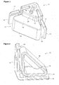
- the oven (1) comprises a cooking chamber (2) into which the objects to be cooked are placed, a door (3) that allows access to the cooking chamber (2), an outer panel (4) situated on the door (3) and that forms the surface of the door (3) that contacts the outside, an inner panel (5) forming the surface of the door (3) that contacts the cooking chamber (2), a casing (7) situated between the outer panel (4) and the inner panel (5), on one side of which the outer panel (4) is fixed and on the other side of which the inner panel (5) is fixed in such a manner that the outer (4) and the inner panels (5) are parallel to each other, which has quadrangular profiles (8) and which is formed by joining together the profiles (8) in the U-form and an intermediate panel (6) disposed into the casing (7) in such a manner that it is located between the outer panel (4) and the inner panel (5) ( Figure 1 and Figure 2 ).
- the door (3) comprises at least two housings (9) situated on at least two corners where the profiles (8) intersect and one or more brackets (10) mounted on the housing (9) in such a manner that one part of it remains inside the casing (7) and one part of it remains outside the casing, and that extend between the inner panel (5) and the outer panel (4), and onto which the intermediate panel (6) is seated.
- the part of the bracket (10) inside the casing (7) remains between the profile (8) walls.
- the part outside the casing (7) is outside the profiles (8).
- the bracket (10) provides the adjusting of the distance both between the inner panel (5) and the outer panel (4) and also the distance of the intermediate panel (6) to the inner and outer panels (5 and 4).
- the bracket (10) is mounted on the casing (7) from above, thus it can be easily dismounted from the casing (7) by the maintenance personnel.
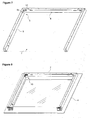
- the bracket (10) is in the form of prism, having a base (11) onto which the outer panel (4) seats and a ceiling (12) bearing against the inner panel (5) mounted on the casing (7) and the walls (13) joining the base (11) and the ceiling (12).
- the bracket (10) is in the form of right triangular prism.
- the bracket (10) also comprises a stepped platform (14) disposed between the base (11) and the ceiling (12), having a support surface (19) onto which the intermediate panel (6) seats and a stopper (20) perpendicular to this support surface (19) and two slits (15) that extend along the two walls (13) perpendicular to each other, between the base (11) and the ceiling (12), in such a manner that these slits (15) don't join in the corner where the two perpendicular walls (13) intersect but open outwardly in the other corners by diverging from each other.
- Platform (14) is surrounded by slits (15) from both sides ( Figure 3, Figure 4 , Figure 5 and Figure 6 ).
- the housing (9) extends to surround the corner, in the corner where the profiles (8) intersect, over the surface onto which the inner panel (5) seats, on both sides of the corner in the horizontal plane.
- the housing (9) extends between the two profiles (8) perpendicular to each other, along the corner where the two profiles (8) intersect in the vertical plane and is configured by performing cut-out operation on the edges of the casing (7) where the profiles (8) intersect.
- the casing (7) is reverse "U"-shaped and the surface area of the outer panel (4) is larger than the area that the casing (7) covers.
- the inner panel (5) is almost equal to the area that the casing (7) surrounds.
- the intermediate panel (6) is situated between the profiles (8) forming the casing (7).
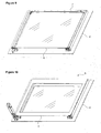
- the casing (7) extends continuously parallel to the three edges of the panels (4, 5 and 6) ( Figure 7 ).
- the panels (4, 5 and 6) are mounted on the door (3) as follows. First of all, the casing (7) is fixed on the outer panel (4) preferably by adhering.
- Two brackets (10) are mounted on the two housings (9) situated on the two upper edges of the casing (7). The bracket (10) is inserted from above into the housing (9) configured on the upper surface of the casing (7) and along the corner of the casing (7) along the corner where the profiles (8) intersect. During this operation, the profiles (8) situated on both sides of the corner enter into the two slits (15) and the base (11) of the bracket (10) bears against the outer panel (4).
- the intermediate panel (6) After the bracket (10) is mounted on the casing (7), the intermediate panel (6) has to be seated in such a manner that it will correspond to the support surface (19) of the platform (14) and is parallel to the outer panel (4) mounted on the casing.
- the corner of the intermediate panel (6) is cut in a shape suitable for the stopper (20).
- the intermediate panel (6) seating on the support surface (19) bears against the stopper (20).
- the height of the support surface (19) from the base (11) determines the distance of the intermediate panel (6) to the outer panel (4) ( Figure 9 ).
- the inner panel (5) is fixed on the casing (7) preferably by adhering.
- the inner panel (5) bears against the ceiling (12) of the bracket (10) and the assembly of the panels (4, 5 and 6) on the door (3) is completed.
- the bracket (10) bears at its base (11) against the outer panel (4) and at its ceiling (12) against the inner panel (5) ( Figure 10 ).
- the door (3) comprises a recess (16) situated on the part of the profile (8) which enters into the slit (15) and a protrusion (17) each in the form of a detent that seats into the recess (16) by stretching while the bracket (10) is mounted on the housing (9) and which are situated on the walls (13) perpendicular to each other of the bracket (10).
- the protrusion (17) seats in the recess (16)
- the movement of the bracket (10) is prevented in the vertical plane and the dismounting of the bracket (10) from the casing (7) is prevented as long as the protrusion (17) isn't removed from the recess (16).
- the ceiling (12) comprises a support (18) in the form of a protrusion that bears against the inner panel (5).
- the support surface (19) of the bracket (10) is in the form of a cavity.
- the intermediate panel (6) is inserted into the support surface (19).
- the intermediate panel (6) is supported from both the bottom and also from the top by the bracket (10) by means of support surface (19).
- the bracket (10) while the bracket (10) is fixed on the profile (8) from one of its edges by means of the fixing element, its other edge enters into the profile (8) ( Figure 11 and Figure 12 ).
- the assembly and disassembly of the panels (4, 5 and 6) to the door (3) is facilitated and the easy removal of the bracket (10) from the casing (7) by the maintenance personnel is provided.
Claims (3)
- Ofen (1), umfassend eine Zubereitungskammer (2), in die zu garende Objekte gelegt werden, eine Tür (3), die Zugriff auf die Zubereitungskammer (2) bietet, eine Außenverkleidung (4), die an der Tür (3) angeordnet ist und die Oberfläche der Tür (3) bildet, welche in Außenkontakt steht, eine Innenverkleidung (5), welche die Oberfläche der Tür (3) bildet, die in Kontakt mit der Zubereitungskammer (2) steht, ein Gehäuse (7) zwischen der Außenverkleidung (4) und der Innenverkleidung (5), an dessen einer Seite die Außenverkleidung (4) gesichert ist und an dessen anderer Seite die Innenverkleidung (5) gesichert ist, derart, das die Außenverkleidung (4) und die Innenverkleidung (5) parallel zueinander ist, und eine Zwischenverkleidung (6), die derart im Gehäuse (7) angeordnet ist, dass sie zwischen der Außenverkleidung (4) und der Innenverkleidung (5) positioniert ist, wobei die Tür (3) Folgendes aufweist- wenigstens zwei Gehäuse (9), die an wenigstens zwei Ecken angeordnet sind, an denen die Profile (8) des Gehäuses (7) sich schneiden, und- eine oder mehrere Halterungen (10), die derart am Gehäuse (9) angebracht sind, dass ein Teil von ihnen im Inneren des Gehäuses (7) bleibt und ein Teil von ihnen außerhalb des Gehäuses (7) bleibt, und die sich zwischen der Innenverkleidung (5) und der Außenverkleidung (4) erstrecken, und auf denen die Zwischenverkleidung (6) ruht, wobei eine Halterung (10) die Form eines Prisma aufweist und eine Basis (11), auf der die Außenverkleidung (4) ruht, und eine Decke (12), die an der Innenverkleidung (5) anliegt und am Gehäuse (7) angebracht ist, und Wände (13) aufweist, die die Basis (11) und die Decke (12) verbinden, und ferner eine gestufte Plattform (14) umfasst, die zwischen der Basis (11) und der Decke (12) angeordnet ist und eine Trägerfläche (19), auf der die Zwischenverkleidung (6) ruht, und einen Anschlag (20) senkrecht zu dieser Trägerfläche (19) aufweist,
wobei der Ofen (1) ein Gehäuse (9) aufweist, das durch einen Ausnehmungsvorgang an den Kanten des Gehäuses (7) konfiguriert ist, wo sich die Profile (8) schneiden, und das sich an der Ecke, an der sich die Profile (8) schneiden, auf beiden Seiten der Ecke an der Fläche, auf der die Innenverkleidung (5) ruht, erstreckt, derart, dass es die Ecke umgibt und sich zwischen den zwei Profilen (8), die senkrecht zueinander sind, entlang der Ecke erstreckt, wo sich die Profile (8) in der vertikalen Ebene schneiden,
und eine Vertiefung (16) umfasst, die an dem Abschnitt des Profils (8) angeordnet ist, der in den Schlitz (15) eintritt,
dadurch gekennzeichnet, dass das Gehäuse (7) quadratische Profile (8) aufweist, die durch Verbinden der Profile (8) in einer U-Form gebildet sind,
und durch eine Halterung (10), die zwei Schlitze (15) umfasst, die sich zwischen der Basis (11) und der Decke (12) entlang den zwei Wänden (13) senkrecht zueinander erstrecken, derart, dass die Schlitze (15) nicht in der Ecke zusammentreffen, an der sich die Wände (13) schneiden, sondern in den anderen Ecken nach außen geöffnet wird, indem sie sich voneinander entfernen und die Plattform (14) von ihren beiden Seiten aus umgeben, und ferner
dadurch gekennzeichnet, dass die Tür (3) einen Vorsprung (17) in der Form einer Ausnehmung umfasst, der in der Vertiefung (16) ruht, indem er gestreckt ist, während die Halterung (10) am Gehäuse (9) angebracht ist, und der an den Wänden (13) der Halterung (10) angeordnet ist, die senkrecht zueinander sind. - Ofen (1) nach Anspruch 1, dadurch gekennzeichnet, dass die Halterung (10) die Form eines dreieckigen Prismas aufweist.
- Ofen (1) nach Anspruch 1, dadurch gekennzeichnet, dass die Decke (12) einen Träger (18) in der Form eines Vorsprungs umfasst, der an der Innenverkleidung (5) anliegt.
Applications Claiming Priority (2)
| Application Number | Priority Date | Filing Date | Title |
|---|---|---|---|
| TR200806826 | 2008-09-09 | ||
| PCT/EP2009/061645 WO2010029083A1 (en) | 2008-09-09 | 2009-09-08 | An oven |
Publications (2)
| Publication Number | Publication Date |
|---|---|
| EP2329198A1 EP2329198A1 (de) | 2011-06-08 |
| EP2329198B1 true EP2329198B1 (de) | 2015-08-12 |
Family
ID=41510825
Family Applications (1)
| Application Number | Title | Priority Date | Filing Date |
|---|---|---|---|
| EP09782778.6A Not-in-force EP2329198B1 (de) | 2008-09-09 | 2009-09-08 | Ofen |
Country Status (2)
| Country | Link |
|---|---|
| EP (1) | EP2329198B1 (de) |
| WO (1) | WO2010029083A1 (de) |
Family Cites Families (12)
| Publication number | Priority date | Publication date | Assignee | Title |
|---|---|---|---|---|
| US4106476A (en) * | 1976-06-28 | 1978-08-15 | Pacific Fireplace Furnishings, Inc. | Door for fireplace screen |
| EP2466215A1 (de) * | 1999-08-31 | 2012-06-20 | Electrolux Rothenburg GmbH Factory and Development | Tür für ein Gerät, insbesondere einen Garofen, mit Scheibenhalter für mehrere Scheiben |
| DE10143926B4 (de) * | 2001-09-07 | 2004-06-24 | BSH Bosch und Siemens Hausgeräte GmbH | Gargerätetür |
| DE10243552A1 (de) * | 2002-09-19 | 2004-04-01 | BSH Bosch und Siemens Hausgeräte GmbH | Backofentür und Türboden dafür |
| DE102005004944B4 (de) * | 2003-08-04 | 2007-05-16 | Miele & Cie | Tür für ein Haushaltsgerät mit demontierbarer Scheibe |
| DE10336138B3 (de) | 2003-08-04 | 2004-10-14 | Miele & Cie. Kg | Tür für ein Haushaltsgerät mit demontierbarer Scheibe |
| ITPD20040079U1 (it) * | 2004-11-03 | 2005-02-03 | Unox Spa | Struttura di porta per forni particolarmente per alimenti e simili |
| FR2892182B1 (fr) * | 2005-10-17 | 2008-01-18 | Brandt Ind Sas | Porte pour enceinte de cuisson |
| ITPD20050080U1 (it) | 2005-10-18 | 2007-04-19 | Unox Spa | Struttura di porta per forno di cottura ad uso alimentare |
| KR100743286B1 (ko) * | 2005-12-12 | 2007-07-26 | 엘지전자 주식회사 | 오븐의 도어 |
| EP2011399B1 (de) * | 2007-07-02 | 2011-03-09 | Electrolux Home Products Corporation N.V. | Ofentür mit Türrahmen und Türblatt |
| DE102007040670B4 (de) * | 2007-08-27 | 2012-07-19 | Miele & Cie. Kg | Vorrichtung zum Verbinden von Glasscheiben einer Haushaltsgerätetür |
-
2009
- 2009-09-08 WO PCT/EP2009/061645 patent/WO2010029083A1/en active Application Filing
- 2009-09-08 EP EP09782778.6A patent/EP2329198B1/de not_active Not-in-force
Also Published As
| Publication number | Publication date |
|---|---|
| WO2010029083A1 (en) | 2010-03-18 |
| EP2329198A1 (de) | 2011-06-08 |
Similar Documents
| Publication | Publication Date | Title |
|---|---|---|
| US9372002B2 (en) | Household appliance having an oven door with an integral drip tray | |
| KR101760149B1 (ko) | 배출기 후드용 내부 프레임 및 배출기 후드 | |
| EP2938930B1 (de) | Tür mit abnehmbaren platten und ofen mit dieser tür | |
| US5791336A (en) | Frameless cooktop | |
| US20220364735A1 (en) | Method for the realization of cooking apparatuses | |
| WO2006041603A2 (en) | Barbecue grill assembly | |
| EP2314931B1 (de) | Tragestruktur für ein Haushaltsgerät | |
| CA2886151C (en) | Refrigerated display case | |
| JP4820709B2 (ja) | 加熱調理器 | |
| EP2329198B1 (de) | Ofen | |
| JP2018204852A (ja) | レンジフードパネル取付具 | |
| US11703231B2 (en) | Hemmed shelf for appliance-module assembly | |
| EP3282196B1 (de) | Anordnung bestehend aus einer abzugshaube und einem wandschrank | |
| EP2370738B1 (de) | Ofen, umfassend eine tür | |
| CN213746862U (zh) | 集成灶框架及集成灶 | |
| EP1590605A1 (de) | Küchenherd | |
| US20190125078A1 (en) | Mounting device and domestic appliance | |
| EP3324127B1 (de) | Backofen | |
| US20240151405A1 (en) | Locating features for a front panel of a domestic appliance door | |
| US20110115352A1 (en) | Shelf Element | |
| CN110307690B (zh) | 具有特别地固定的板状冷藏物托架的家用制冷器具 | |
| WO2020120783A1 (en) | Cooking appliance with a top sheet | |
| JP6837339B2 (ja) | レンジフード | |
| JP2022027213A (ja) | キッチンユニット | |
| KR101030498B1 (ko) | 냉장고용 선반 |
Legal Events
| Date | Code | Title | Description |
|---|---|---|---|
| PUAI | Public reference made under article 153(3) epc to a published international application that has entered the european phase |
Free format text: ORIGINAL CODE: 0009012 |
|
| 17P | Request for examination filed |
Effective date: 20110323 |
|
| AK | Designated contracting states |
Kind code of ref document: A1 Designated state(s): AT BE BG CH CY CZ DE DK EE ES FI FR GB GR HR HU IE IS IT LI LT LU LV MC MK MT NL NO PL PT RO SE SI SK SM TR |
|
| AX | Request for extension of the european patent |
Extension state: AL BA RS |
|
| DAX | Request for extension of the european patent (deleted) | ||
| 17Q | First examination report despatched |
Effective date: 20130409 |
|
| GRAP | Despatch of communication of intention to grant a patent |
Free format text: ORIGINAL CODE: EPIDOSNIGR1 |
|
| INTG | Intention to grant announced |
Effective date: 20150422 |
|
| GRAS | Grant fee paid |
Free format text: ORIGINAL CODE: EPIDOSNIGR3 |
|
| GRAA | (expected) grant |
Free format text: ORIGINAL CODE: 0009210 |
|
| AK | Designated contracting states |
Kind code of ref document: B1 Designated state(s): AT BE BG CH CY CZ DE DK EE ES FI FR GB GR HR HU IE IS IT LI LT LU LV MC MK MT NL NO PL PT RO SE SI SK SM TR |
|
| REG | Reference to a national code |
Ref country code: GB Ref legal event code: FG4D |
|
| REG | Reference to a national code |
Ref country code: CH Ref legal event code: EP |
|
| REG | Reference to a national code |
Ref country code: AT Ref legal event code: REF Ref document number: 742515 Country of ref document: AT Kind code of ref document: T Effective date: 20150815 |
|
| REG | Reference to a national code |
Ref country code: IE Ref legal event code: FG4D |
|
| REG | Reference to a national code |
Ref country code: DE Ref legal event code: R096 Ref document number: 602009032881 Country of ref document: DE |
|
| REG | Reference to a national code |
Ref country code: FR Ref legal event code: PLFP Year of fee payment: 7 |
|
| REG | Reference to a national code |
Ref country code: LT Ref legal event code: MG4D |
|
| REG | Reference to a national code |
Ref country code: AT Ref legal event code: MK05 Ref document number: 742515 Country of ref document: AT Kind code of ref document: T Effective date: 20150812 |
|
| REG | Reference to a national code |
Ref country code: NL Ref legal event code: MP Effective date: 20150812 |
|
| PG25 | Lapsed in a contracting state [announced via postgrant information from national office to epo] |
Ref country code: GR Free format text: LAPSE BECAUSE OF FAILURE TO SUBMIT A TRANSLATION OF THE DESCRIPTION OR TO PAY THE FEE WITHIN THE PRESCRIBED TIME-LIMIT Effective date: 20151113 Ref country code: FI Free format text: LAPSE BECAUSE OF FAILURE TO SUBMIT A TRANSLATION OF THE DESCRIPTION OR TO PAY THE FEE WITHIN THE PRESCRIBED TIME-LIMIT Effective date: 20150812 Ref country code: LT Free format text: LAPSE BECAUSE OF FAILURE TO SUBMIT A TRANSLATION OF THE DESCRIPTION OR TO PAY THE FEE WITHIN THE PRESCRIBED TIME-LIMIT Effective date: 20150812 Ref country code: NO Free format text: LAPSE BECAUSE OF FAILURE TO SUBMIT A TRANSLATION OF THE DESCRIPTION OR TO PAY THE FEE WITHIN THE PRESCRIBED TIME-LIMIT Effective date: 20151112 Ref country code: LV Free format text: LAPSE BECAUSE OF FAILURE TO SUBMIT A TRANSLATION OF THE DESCRIPTION OR TO PAY THE FEE WITHIN THE PRESCRIBED TIME-LIMIT Effective date: 20150812 |
|
| PG25 | Lapsed in a contracting state [announced via postgrant information from national office to epo] |
Ref country code: AT Free format text: LAPSE BECAUSE OF FAILURE TO SUBMIT A TRANSLATION OF THE DESCRIPTION OR TO PAY THE FEE WITHIN THE PRESCRIBED TIME-LIMIT Effective date: 20150812 Ref country code: PT Free format text: LAPSE BECAUSE OF FAILURE TO SUBMIT A TRANSLATION OF THE DESCRIPTION OR TO PAY THE FEE WITHIN THE PRESCRIBED TIME-LIMIT Effective date: 20151214 Ref country code: SE Free format text: LAPSE BECAUSE OF FAILURE TO SUBMIT A TRANSLATION OF THE DESCRIPTION OR TO PAY THE FEE WITHIN THE PRESCRIBED TIME-LIMIT Effective date: 20150812 Ref country code: IS Free format text: LAPSE BECAUSE OF FAILURE TO SUBMIT A TRANSLATION OF THE DESCRIPTION OR TO PAY THE FEE WITHIN THE PRESCRIBED TIME-LIMIT Effective date: 20151212 Ref country code: PL Free format text: LAPSE BECAUSE OF FAILURE TO SUBMIT A TRANSLATION OF THE DESCRIPTION OR TO PAY THE FEE WITHIN THE PRESCRIBED TIME-LIMIT Effective date: 20150812 Ref country code: ES Free format text: LAPSE BECAUSE OF FAILURE TO SUBMIT A TRANSLATION OF THE DESCRIPTION OR TO PAY THE FEE WITHIN THE PRESCRIBED TIME-LIMIT Effective date: 20150812 Ref country code: HR Free format text: LAPSE BECAUSE OF FAILURE TO SUBMIT A TRANSLATION OF THE DESCRIPTION OR TO PAY THE FEE WITHIN THE PRESCRIBED TIME-LIMIT Effective date: 20150812 |
|
| PG25 | Lapsed in a contracting state [announced via postgrant information from national office to epo] |
Ref country code: NL Free format text: LAPSE BECAUSE OF FAILURE TO SUBMIT A TRANSLATION OF THE DESCRIPTION OR TO PAY THE FEE WITHIN THE PRESCRIBED TIME-LIMIT Effective date: 20150812 |
|
| PG25 | Lapsed in a contracting state [announced via postgrant information from national office to epo] |
Ref country code: EE Free format text: LAPSE BECAUSE OF FAILURE TO SUBMIT A TRANSLATION OF THE DESCRIPTION OR TO PAY THE FEE WITHIN THE PRESCRIBED TIME-LIMIT Effective date: 20150812 Ref country code: IT Free format text: LAPSE BECAUSE OF FAILURE TO SUBMIT A TRANSLATION OF THE DESCRIPTION OR TO PAY THE FEE WITHIN THE PRESCRIBED TIME-LIMIT Effective date: 20150812 Ref country code: CZ Free format text: LAPSE BECAUSE OF FAILURE TO SUBMIT A TRANSLATION OF THE DESCRIPTION OR TO PAY THE FEE WITHIN THE PRESCRIBED TIME-LIMIT Effective date: 20150812 Ref country code: DK Free format text: LAPSE BECAUSE OF FAILURE TO SUBMIT A TRANSLATION OF THE DESCRIPTION OR TO PAY THE FEE WITHIN THE PRESCRIBED TIME-LIMIT Effective date: 20150812 Ref country code: SK Free format text: LAPSE BECAUSE OF FAILURE TO SUBMIT A TRANSLATION OF THE DESCRIPTION OR TO PAY THE FEE WITHIN THE PRESCRIBED TIME-LIMIT Effective date: 20150812 |
|
| REG | Reference to a national code |
Ref country code: CH Ref legal event code: PL |
|
| REG | Reference to a national code |
Ref country code: DE Ref legal event code: R097 Ref document number: 602009032881 Country of ref document: DE |
|
| PG25 | Lapsed in a contracting state [announced via postgrant information from national office to epo] |
Ref country code: MC Free format text: LAPSE BECAUSE OF FAILURE TO SUBMIT A TRANSLATION OF THE DESCRIPTION OR TO PAY THE FEE WITHIN THE PRESCRIBED TIME-LIMIT Effective date: 20150812 Ref country code: RO Free format text: LAPSE BECAUSE OF FAILURE TO SUBMIT A TRANSLATION OF THE DESCRIPTION OR TO PAY THE FEE WITHIN THE PRESCRIBED TIME-LIMIT Effective date: 20150812 |
|
| PLBE | No opposition filed within time limit |
Free format text: ORIGINAL CODE: 0009261 |
|
| STAA | Information on the status of an ep patent application or granted ep patent |
Free format text: STATUS: NO OPPOSITION FILED WITHIN TIME LIMIT |
|
| REG | Reference to a national code |
Ref country code: IE Ref legal event code: MM4A |
|
| 26N | No opposition filed |
Effective date: 20160513 |
|
| PG25 | Lapsed in a contracting state [announced via postgrant information from national office to epo] |
Ref country code: IE Free format text: LAPSE BECAUSE OF NON-PAYMENT OF DUE FEES Effective date: 20150908 Ref country code: CH Free format text: LAPSE BECAUSE OF NON-PAYMENT OF DUE FEES Effective date: 20150930 Ref country code: LI Free format text: LAPSE BECAUSE OF NON-PAYMENT OF DUE FEES Effective date: 20150930 |
|
| PG25 | Lapsed in a contracting state [announced via postgrant information from national office to epo] |
Ref country code: SI Free format text: LAPSE BECAUSE OF FAILURE TO SUBMIT A TRANSLATION OF THE DESCRIPTION OR TO PAY THE FEE WITHIN THE PRESCRIBED TIME-LIMIT Effective date: 20150812 |
|
| REG | Reference to a national code |
Ref country code: FR Ref legal event code: PLFP Year of fee payment: 8 |
|
| PGFP | Annual fee paid to national office [announced via postgrant information from national office to epo] |
Ref country code: GB Payment date: 20160920 Year of fee payment: 8 Ref country code: DE Payment date: 20160921 Year of fee payment: 8 |
|
| PGFP | Annual fee paid to national office [announced via postgrant information from national office to epo] |
Ref country code: FR Payment date: 20160921 Year of fee payment: 8 |
|
| PG25 | Lapsed in a contracting state [announced via postgrant information from national office to epo] |
Ref country code: BE Free format text: LAPSE BECAUSE OF FAILURE TO SUBMIT A TRANSLATION OF THE DESCRIPTION OR TO PAY THE FEE WITHIN THE PRESCRIBED TIME-LIMIT Effective date: 20150812 |
|
| PGFP | Annual fee paid to national office [announced via postgrant information from national office to epo] |
Ref country code: TR Payment date: 20160822 Year of fee payment: 8 |
|
| PG25 | Lapsed in a contracting state [announced via postgrant information from national office to epo] |
Ref country code: MT Free format text: LAPSE BECAUSE OF FAILURE TO SUBMIT A TRANSLATION OF THE DESCRIPTION OR TO PAY THE FEE WITHIN THE PRESCRIBED TIME-LIMIT Effective date: 20150812 |
|
| PG25 | Lapsed in a contracting state [announced via postgrant information from national office to epo] |
Ref country code: HU Free format text: LAPSE BECAUSE OF FAILURE TO SUBMIT A TRANSLATION OF THE DESCRIPTION OR TO PAY THE FEE WITHIN THE PRESCRIBED TIME-LIMIT; INVALID AB INITIO Effective date: 20090908 Ref country code: SM Free format text: LAPSE BECAUSE OF FAILURE TO SUBMIT A TRANSLATION OF THE DESCRIPTION OR TO PAY THE FEE WITHIN THE PRESCRIBED TIME-LIMIT Effective date: 20150812 Ref country code: BG Free format text: LAPSE BECAUSE OF FAILURE TO SUBMIT A TRANSLATION OF THE DESCRIPTION OR TO PAY THE FEE WITHIN THE PRESCRIBED TIME-LIMIT Effective date: 20150812 |
|
| PG25 | Lapsed in a contracting state [announced via postgrant information from national office to epo] |
Ref country code: CY Free format text: LAPSE BECAUSE OF FAILURE TO SUBMIT A TRANSLATION OF THE DESCRIPTION OR TO PAY THE FEE WITHIN THE PRESCRIBED TIME-LIMIT Effective date: 20150812 |
|
| PG25 | Lapsed in a contracting state [announced via postgrant information from national office to epo] |
Ref country code: LU Free format text: LAPSE BECAUSE OF NON-PAYMENT OF DUE FEES Effective date: 20150908 |
|
| REG | Reference to a national code |
Ref country code: DE Ref legal event code: R119 Ref document number: 602009032881 Country of ref document: DE |
|
| GBPC | Gb: european patent ceased through non-payment of renewal fee |
Effective date: 20170908 |
|
| PG25 | Lapsed in a contracting state [announced via postgrant information from national office to epo] |
Ref country code: MK Free format text: LAPSE BECAUSE OF FAILURE TO SUBMIT A TRANSLATION OF THE DESCRIPTION OR TO PAY THE FEE WITHIN THE PRESCRIBED TIME-LIMIT Effective date: 20150812 |
|
| REG | Reference to a national code |
Ref country code: FR Ref legal event code: ST Effective date: 20180531 |
|
| PG25 | Lapsed in a contracting state [announced via postgrant information from national office to epo] |
Ref country code: GB Free format text: LAPSE BECAUSE OF NON-PAYMENT OF DUE FEES Effective date: 20170908 Ref country code: DE Free format text: LAPSE BECAUSE OF NON-PAYMENT OF DUE FEES Effective date: 20180404 |
|
| PG25 | Lapsed in a contracting state [announced via postgrant information from national office to epo] |
Ref country code: FR Free format text: LAPSE BECAUSE OF NON-PAYMENT OF DUE FEES Effective date: 20171002 |
|
| PG25 | Lapsed in a contracting state [announced via postgrant information from national office to epo] |
Ref country code: TR Free format text: LAPSE BECAUSE OF NON-PAYMENT OF DUE FEES Effective date: 20170908 |