EP2329133B1 - Brennstoffeinspritzventil - Google Patents
Brennstoffeinspritzventil Download PDFInfo
- Publication number
- EP2329133B1 EP2329133B1 EP09780220.1A EP09780220A EP2329133B1 EP 2329133 B1 EP2329133 B1 EP 2329133B1 EP 09780220 A EP09780220 A EP 09780220A EP 2329133 B1 EP2329133 B1 EP 2329133B1
- Authority
- EP
- European Patent Office
- Prior art keywords
- hole
- spray hole
- fuel injection
- region
- injection valve
- Prior art date
- Legal status (The legal status is an assumption and is not a legal conclusion. Google has not performed a legal analysis and makes no representation as to the accuracy of the status listed.)
- Not-in-force
Links
- 238000002347 injection Methods 0.000 title claims description 52
- 239000007924 injection Substances 0.000 title claims description 52
- 239000000446 fuel Substances 0.000 title claims description 40
- 239000007921 spray Substances 0.000 claims description 28
- 230000007423 decrease Effects 0.000 claims description 13
- 238000007789 sealing Methods 0.000 claims description 6
- 238000002485 combustion reaction Methods 0.000 claims description 4
- 238000000926 separation method Methods 0.000 claims 1
- 238000000889 atomisation Methods 0.000 description 8
- 230000001154 acute effect Effects 0.000 description 1
- 230000001419 dependent effect Effects 0.000 description 1
- 230000006866 deterioration Effects 0.000 description 1
- 238000011161 development Methods 0.000 description 1
- 230000018109 developmental process Effects 0.000 description 1
- 239000002283 diesel fuel Substances 0.000 description 1
- 238000005457 optimization Methods 0.000 description 1
- 238000005507 spraying Methods 0.000 description 1
Images

Classifications
-
- F—MECHANICAL ENGINEERING; LIGHTING; HEATING; WEAPONS; BLASTING
- F02—COMBUSTION ENGINES; HOT-GAS OR COMBUSTION-PRODUCT ENGINE PLANTS
- F02M—SUPPLYING COMBUSTION ENGINES IN GENERAL WITH COMBUSTIBLE MIXTURES OR CONSTITUENTS THEREOF
- F02M61/00—Fuel-injectors not provided for in groups F02M39/00 - F02M57/00 or F02M67/00
- F02M61/16—Details not provided for in, or of interest apart from, the apparatus of groups F02M61/02 - F02M61/14
- F02M61/18—Injection nozzles, e.g. having valve seats; Details of valve member seated ends, not otherwise provided for
- F02M61/1806—Injection nozzles, e.g. having valve seats; Details of valve member seated ends, not otherwise provided for characterised by the arrangement of discharge orifices, e.g. orientation or size
Definitions
- the invention relates to a fuel injection valve, in particular an injector for fuel injection systems of air-compressing, self-igniting internal combustion engines.
- the known fuel injection valve has a valve body in which a pressure chamber is formed, in the wall of which an injection channel is arranged.
- the injection channel extends in the valve body and forms an outlet opening on the outside of the valve body.
- the injection channel seen in the flow direction comprises a first conical portion and an adjoining second conical portion.
- the two conical sections narrow in the direction of flow. Furthermore, the two conical sections have different opening angles.
- the fuel injection valve according to the invention with the features of claim 1 has the advantage that a further optimization of a nozzle-near atomization at a high efficiency is possible. Specifically, a nozzle-near atomization can take place without a significant deterioration of the efficiency takes place. Specifically, deflection losses can be substantially avoided or completely prevented.
- the inflow region of the injection hole is rounded, while the outer hole region is sharp-edged and free of burrs.
- the rounded-off inflow region preferably proceeds uniformly and without edges into a valve seat surface.
- a wall of the spray hole is configured such that a flow line extending in the flow direction along a surface of the wall is designed kink-free. As a result, turbulence in the region of the surface of the wall of the spray hole is prevented, whereby flow losses are reduced.
- a cross-sectional area of the injection hole perpendicular to an axis oriented in the flow direction of the injection hole decreases continuously along the axis in the flow direction.
- a continuous narrowing of the spray hole is achieved in the flow direction, which can run uniformly, at least in a central portion.
- the efficiency can be optimized.
- the cross-sectional area decreases relatively strongly in the outer hole area along the axis in the flow direction.
- the decrease in the cross-sectional area in a middle region between the inflow region and the outer hole region in the flow direction may decrease uniformly, wherein the decrease of the cross-sectional area in the flow direction in the central region is preferably relatively weak.
- a deflection can be achieved, which takes place in the middle region towards the axis and is more pronounced in the outer hole region.
- nozzle-near atomization can be achieved with high efficiency.
- a tear-off edge is provided in the outer hole region of the injection hole, which is directed onto the axis of the injection hole. As a result, the atomization of the sprayed fuel can be improved.
- Fig. 1 shows a fuel injection valve 1 in a schematic, partial sectional view according to an embodiment of the invention.
- the fuel injection valve 1 can serve in particular as an injector for fuel injection systems of air-compressing, self-igniting internal combustion engines.
- a preferred use of the fuel injection valve 1 is for a fuel injection system with a common rail, the diesel fuel under high pressure leads to a plurality of fuel injection valves 1.
- the fuel injection valve 1 according to the invention is also suitable for other applications.
- Partially illustrated fuel injector 1 has a nozzle body 2, in which a nozzle needle 3 is mounted axially displaceable.
- the nozzle needle 3 is actuated by means of an actuator 4.
- the actuator 4 may, for example have mechanical and hydraulic components, wherein the control can be effected by means of a piezoelectric actuator or a solenoid valve.
- the action of the actuating device 4 on the nozzle needle 3 is illustrated by the double arrow 5.
- the fuel injection valve 1 is suitably connected to a fuel pump, for example via a common rail. During operation of the fuel injection valve 1, therefore, there is fuel under high pressure in a fuel space 6 provided inside the nozzle body 2.
- the nozzle body 2 has a valve seat surface 7 which cooperates with a valve closing body 8 of the nozzle needle 3 to form a sealing seat.
- the sealing seat is formed on a sealing edge 9 of the valve seat surface 7. Downstream of the sealing edge 9, the nozzle body 2 has at least one injection hole 15.
- the injection hole 15 is configured in this embodiment as a blind-hole injection port 15.
- the spray hole 15 may be configured as a seat hole nozzle injection hole in a suitably designed fuel injector 1.
- the injection hole 15 has an inflow region 16, a central region 17 and an outer hole region 18.
- the middle region 17 is located between the inflow region 16 and the outer hole region 18 of the injection hole 15.
- the injection hole 15 is rounded in the inflow region 16.
- the injection hole 15 in the outer hole portion 18 has a taper.
- the injection hole 15 is also in the outer hole area 18th rounded out.
- a wall 19 of the injection hole 15 is designed so that no steps, edges, kinks or the like are formed in a surface 20 of the wall 19.
- the surface 20 of the wall 19 is thus at least substantially smooth and uniform.
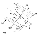
- the configuration of the injection hole 15 is also in the following with reference to Fig. 2 described in further detail.
- Fig. 2 shows the in Fig. 1 With II designated section of the nozzle body 2 of the fuel injection valve 1 in a schematic sectional view.
- the injection hole 15 has an axis 25, wherein the axis 25 is oriented at least approximately in a flow direction 26.
- the injection hole 15 is at least approximately symmetrical with respect to the axis 25 configured.
- a flow line 27 is shown which runs along the surface 20 of the wall 19 of the spray hole 15. It should be noted that the flow line 27 is not in the in the Fig. 2 Section shown extends, since it lies in the surface 20 of the wall 19.
- the flow line 27 is designed kink-free. As a result, the flow line 27 is both continuous, that is, without steps, as well as even, that is, without abrupt changes in direction along their path, along the surface 20 of the wall 19 out. As a result, in particular turbulences are reduced or completely prevented. As a result, a high efficiency can be achieved when flowing through the spray hole 15 with fuel.
- a cross-sectional area 28 is illustrated, which is oriented perpendicular to the axis 25 of the spray hole 15.
- the cross-sectional area 28 of the spray hole 15 may be configured, for example, at least approximately circular or elliptical.
- the injection hole 15 is designed such that the cross-sectional area 28 decreases along the axis 25 in the flow direction 26. This decrease takes place continuously, wherein, for example, a diameter of the cross-sectional area 28 decreases continuously or at least one of the two main axes of an elliptical cross-sectional area 28 is steadily reduced.
- the cross-sectional area 28 initially decreases relatively strongly. Furthermore, in a middle region 17 of the spray hole 15, the decrease in the cross-sectional area 28 is relatively weak. In the outer hole region 18, the decrease in the cross-sectional area 28 in the flow direction 26 along the axis 25 is again relatively pronounced. This results in an S-shaped configuration of the flow lines of the spray hole 15, in particular the flow line 27. This allows an advantageous flow through the spray hole 15, wherein the design of the outer hole portion 18, a deflection is achieved, which leads to a nozzle near atomization of the sprayed fuel ,
- the injection hole 15 has in the outer hole region 18 on a circumferential tear-off edge 29, which is configured, for example, circular or elliptical.
- the tear-off edge 29 is directed onto the axis 25 of the spray hole 15.
- the trailing edge 29 supports the atomization of sprayed fuel. This allows a nozzle-near atomization of the fuel with high efficiency.
- the tear-off edge 29 is designed sharp-edged and burr-free.
- an acute angle 31 is formed in the sectional view.
Landscapes
- Engineering & Computer Science (AREA)
- Chemical & Material Sciences (AREA)
- Combustion & Propulsion (AREA)
- Mechanical Engineering (AREA)
- General Engineering & Computer Science (AREA)
- Fuel-Injection Apparatus (AREA)
Description
- Die Erfindung betrifft ein Brennstoffeinspritzventil, insbesondere einen Injektor für Brennstoffeinspritzanlagen von luftverdichtenden, selbstzündenden Brennkraftmaschinen.
- Aus der
DE 103 15 967 A1 ist ein Brennstoffeinspritzventil für Brennkraftmaschinen bekannt. Das bekannte Brennstoffeinspritzventil weist einen Ventilkörper auf, in dem ein Druckraum ausgebildet ist, in dessen Wandung ein Einspritzkanal angeordnet ist. Der Einspritzkanal verläuft im Ventilkörper und bildet an der Außenseite des Ventilkörpers eine Austrittsöffnung. Hierbei umfasst der Einspritzkanal in Strömungsrichtung gesehen einen ersten konischen Abschnitt und einen daran anschließenden zweiten konischen Abschnitt. Dabei verengen sich die beiden konischen Abschnitte in Strömungsrichtung. Ferner weisen die beiden konischen Abschnitte unterschiedliche Öffnungswinkel auf. - Bei dem aus der
DE 103 15 967 A1 bekannten Brennstoffeinspritzventil kann eine gute Zerstäubung und Richtungsstabilität des Einspritzstrahls erzielt werden. - Aus der
WO-A-02/063161 - Das erfindungsgemäße Brennstoffeinspritzventil mit den Merkmalen des Anspruchs 1 hat den Vorteil, dass eine weitere Optimierung einer düsennahen Zerstäubung bei einem hohen Wirkungsgrad möglich ist. Speziell kann eine düsennahe Zerstäubung erfolgen, ohne dass eine wesentliche Verschlechterung des Wirkungsgrades erfolgt. Speziell können Umlenkverluste im Wesentlichen vermieden oder ganz verhindert werden.
- Durch die in den Unteransprüchen aufgeführten Maßnahmen sind vorteilhafte Weiterbildungen des im Anspruch 1 angegebenen Brennstoffeinspritzventils möglich.
- In vorteilhafter Weise ist der Einströmbereich des Spritzloches abgerundet ausgestaltet, während der äußere Lochbereich scharfkantig und gratfrei ausgestaltet ist. Dabei geht der abgerundet ausgestaltete Einströmbereich vorzugsweise gleichmäßig und kantenfrei in eine Ventilsitzfläche über. Dadurch wird ein weitgehend verlustfreies Einströmen von Brennstoff in das Spritzloch erzielt und ein zumindest weitgehend verlustfreies Abspritzen im äußeren Lochbereich ermöglicht.
- Ferner ist es vorteilhaft, dass eine Wand des Spritzloches so ausgestaltet ist, dass eine in Strömungsrichtung entlang einer Oberfläche der Wand verlaufende Strömungslinie knickfrei ausgestaltet ist. Dadurch werden Verwirbelungen im Bereich der Oberfläche der Wand des Spritzloches verhindert, wodurch Strömungsverluste verringert sind.
- Erfindungsgemäß ist die entlang der Oberfläche der Wand verlaufende Strömungslinie S-förmig ausgestaltet , wobei sich die S-förmige Ausgestaltung auch über den Einströmbereich und den äußeren Lochbereich erstreckt.
- Erfindungsgemäß nimmt eine senkrecht zu einer in Strömungsrichtung orientierten Achse des Spritzlochs liegende Querschnittsfläche des Spritzlochs entlang der Achse in der Strömungsrichtung kontinuierlich ab. Somit wird eine stetige Verengung des Spritzloches in Strömungsrichtung erzielt, die zumindest in einem mittleren Abschnitt gleichmäßig verlaufen kann. Dadurch kann der Wirkungsgrad optimiert werden. Ferner ist es vorteilhaft, dass die Querschnittsfläche im äußeren Lochbereich entlang der Achse in der Strömungsrichtung relativ stark ausgeprägt abnimmt. Dabei kann die Abnahme der Querschnittsfläche in einem mittleren Bereich zwischen dem Einströmbereich und dem äußeren Lochbereich in der Strömungsrichtung gleichmäßig abnehmen, wobei die Abnahme der Querschnittsfläche in der Strömungsrichtung in dem mittleren Bereich vorzugsweise relativ schwach ausgeprägt ist. Dadurch kann eine Umlenkung erzielt werden, die im mittleren Bereich zu der Achse hin erfolgt und im äußeren Lochbereich stärker ausgeprägt ist. Dadurch kann eine düsennahe Zerstäubung bei einem hohen Wirkungsgrad erzielt werden.
- Ferner ist es vorteilhaft, dass im äußeren Lochbereich des Spritzlochs eine Abrisskante vorgesehen ist, die auf die Achse des Spritzlochs gerichtet ist. Dadurch kann die Zerstäubung des abgespritzten Brennstoffs verbessert werden.
- Bevorzugte Ausführungsbeispiele der Erfindung sind in der nachfolgenden Beschreibung anhand der beigefügten Zeichnungen, in denen sich entsprechende Elemente mit übereinstimmenden Bezugszeichen versehen sind, näher erläutert. Es zeigt:
-
Fig. 1 eine schematische Darstellung eines Brennstoffeinspritzventils in einer auszugsweisen Schnittdarstellung entsprechend einem Ausführungsbeispiel der Erfindung und -
Fig. 2 den inFig. 1 mit II bezeichneten Ausschnitt in weiterem Detail. -
Fig. 1 zeigt ein Brennstoffeinspritzventil 1 in einer schematischen, auszugsweisen Schnittdarstellung entsprechend einem Ausführungsbeispiel der Erfindung. Das Brennstoffeinspritzventil 1 kann insbesondere als Injektor für Brennstoffeinspritzanlagen von luftverdichtenden, selbstzündenden Brennkraftmaschinen dienen. Ein bevorzugter Einsatz des Brennstoffeinspritzventils 1 besteht für eine Brennstoffeinspritzanlage mit einem Common-Rail, das Dieselbrennstoff unter hohem Druck zu mehreren Brennstoffeinspritzventilen 1 führt. Das erfindungsgemäße Brennstoffeinspritzventil 1 eignet sich jedoch auch für andere Anwendungsfälle. - Das in der
Fig. 1 auszugsweise dargestellte Brennstoffeinspritzventil 1 weist einen Düsenkörper 2 auf, in dem eine Düsennadel 3 axial verschiebbar gelagert ist. Die Düsennadel 3 ist dabei mittels einer Betätigungseinrichtung 4 betätigbar. Die Betätigungseinrichtung 4 kann beispielsweise mechanische und hydraulische Komponenten aufweisen, wobei die Ansteuerung mittels eines piezoelektrischen Aktors oder eines Magnetventils erfolgen kann. Die Einwirkung der Betätigungseinrichtung 4 auf die Düsennadel 3 ist durch den Doppelpfeil 5 veranschaulicht. - Das Brennstoffeinspritzventil 1 ist auf geeignete Weise mit einer Brennstoffpumpe verbunden, beispielsweise über ein Common-Rail. Im Betrieb des Brennstoffeinspritzventils 1 befindet sich daher in einem innerhalb des Düsenkörpers 2 vorgesehenen Brennstoffraum 6 unter hohem Druck stehender Brennstoff.
- Der Düsenkörper 2 weist eine Ventilsitzfläche 7 auf, die mit einem Ventilschließkörper 8 der Düsennadel 3 zu einem Dichtsitz zusammenwirkt. In diesem Ausführungsbeispiel ist der Dichtsitz an einer Dichtkante 9 der Ventilsitzfläche 7 gebildet. Stromabwärts der Dichtkante 9 weist der Düsenkörper 2 zumindest ein Spritzloch 15 auf. Das Spritzloch 15 ist in diesem Ausführungsbeispiel als Sacklochdüsen-Spritzloch 15 ausgestaltet. Das Spritzloch 15 kann bei einem entsprechend ausgestalteten Brennstoffeinspritzventil 1 auch als Sitzlochdüsen-Spritzloch ausgestaltet sein.
- Das Spritzloch 15 weist einen Einströmbereich 16, einen mittleren Bereich 17 und einen äußeren Lochbereich 18 auf. Dabei liegt der mittlere Bereich 17 zwischen dem Einströmbereich 16 und dem äußeren Lochbereich 18 des Spritzlochs 15. Das Spritzloch 15 ist in dem Einströmbereich 16 abgerundet ausgestaltet. Ferner weist das Spritzloch 15 in dem äußeren Lochbereich 18 eine Verjüngung auf.
- Das Spritzloch 15 ist auch in dem äußeren Lochbereich 18 abgerundet ausgestaltet. Insgesamt ist eine Wand 19 des Spritzlochs 15 so ausgestaltet, dass in einer Oberfläche 20 der Wand 19 keine Stufen, Kanten, Knicke oder dergleichen ausgebildet sind. Die Oberfläche 20 der Wand 19 ist somit zumindest im Wesentlichen glatt und gleichmäßig ausgestaltet. Die Ausgestaltung des Spritzlochs 15 ist im folgenden auch anhand der
Fig. 2 im weiteren Detail beschrieben. -
Fig. 2 zeigt den inFig. 1 mit II bezeichneten Ausschnitt des Düsenkörpers 2 des Brennstoffeinspritzventils 1 in einer schematischen Schnittdarstellung. - Das Spritzloch 15 weist eine Achse 25 auf, wobei die Achse 25 zumindest näherungsweise in einer Strömungsrichtung 26 orientiert ist. Das Spritzloch 15 ist zumindest näherungsweise symmetrisch bezüglich der Achse 25 ausgestaltet.
- In der
Fig. 2 ist exemplarisch eine Strömungslinie 27 dargestellt, die entlang der Oberfläche 20 der Wand 19 des Spritzloches 15 verläuft. Dabei ist anzumerken, dass die Strömungslinie 27 nicht in der in derFig. 2 dargestellten Schnittebene verläuft, da sie in der Oberfläche 20 der Wand 19 liegt. - Die Strömungslinie 27 ist knickfrei ausgestaltet. Dadurch ist die Strömungslinie 27 sowohl stetig, das heißt ohne Stufen, als auch gleichmäßig, das heißt ohne abrupte Richtungsänderungen entlang ihres Weges, entlang der Oberfläche 20 der Wand 19 geführt. Dadurch werden insbesondere Verwirbelungen verringert oder ganz verhindert. Dadurch kann ein hoher Wirkungsgrad beim Durchströmen des Spritzloches 15 mit Brennstoff erzielt werden.
- In der
Fig. 2 ist exemplarisch eine Querschnittsfläche 28 veranschaulicht, die senkrecht zu der Achse 25 des Spritzloches 15 orientiert ist. Die Querschnittsfläche 28 des Spritzloches 15 kann beispielsweise zumindest näherungsweise kreis- oder ellipsenförmig ausgestaltet sein. Das Spritzloch 15 ist so ausgestaltet, dass die Querschnittsfläche 28 entlang der Achse 25 in der Strömungsrichtung 26 abnimmt. Diese Abnahme erfolgt dabei kontinuierlich, wobei beispielsweise ein Durchmesser der Querschnittsfläche 28 kontinuierlich abnimmt oder zumindest eine der beiden Hauptachsen einer elliptischen Querschnittsfläche 28 stetig reduziert wird. - In dem Einströmbereich 16 nimmt die Querschnittsfläche 28 zunächst relativ stark ab. Ferner ist in einem mittleren Bereich 17 des Spritzloches 15 die Abnahme der Querschnittsfläche 28 relativ schwach ausgeprägt. In dem äußeren Lochbereich 18 ist die Abnahme der Querschnittsfläche 28 in der Strömungsrichtung 26 entlang der Achse 25 wieder relativ stark ausgeprägt. Somit ergibt sich eine S-förmige Ausgestaltung der Strömungslinien des Spritzloches 15, insbesondere der Strömungslinie 27. Dies ermöglicht eine vorteilhafte Durchströmung des Spritzloches 15, wobei durch die Ausgestaltung des äußeren Lochbereichs 18 eine Umlenkung erzielt ist, die zu einer düsennahen Zerstäubung des abgespritzten Brennstoffes führt.
- Das Spritzloch 15 weist in dem äußeren Lochbereich 18 eine umlaufende Abrisskante 29 auf, die beispielsweise kreislinienförmig oder elliptisch ausgestaltet ist. Die Abrisskante 29 ist auf die Achse 25 des Spritzloches 15 gerichtet. Die Abrisskante 29 unterstützt die Zerstäubung des abgespritzten Brennstoffs. Dadurch ist eine düsennahe Zerstäubung des Brennstoffs mit hohem Wirkungsgrad möglich. Die Abrisskante 29 ist scharfkantig und gratfrei ausgestaltet.
- Zwischen einer Außenfläche 30 des Düsenkörpers 2 und der Wand 19 im äußeren Lochbereich 18 ist in der Schnittdarstellung ein spitzer Winkel 31 ausgebildet.
- Die Erfindung ist nicht auf die beschriebenen Ausführungsbeispiele beschränkt.
Claims (7)
- Brennstoffeinspritzventil (1), insbesondere Injektor für Brennstoffeinspritzanlagen von luftverdichtenden, selbstzündenden Brennkraftmaschinen, mit einem Düsenkörper (2), der eine Ventilsitzfläche (7) aufweist, und einer Düsennadel (3), die mit der Ventilsitzfläche (7) zu einem Dichtsitz zusammenwirkt, um einen Brennstofffluss zu zumindest einem stromabwärts des Dichtsitzes vorgesehenen Spritzloch (15) des Düsenkörpers (2) zu steuern, wobei das Spritzloch (15) in einem Einströmbereich (16) abgerundet ausgestaltet ist und das Spritzloch (15) zumindest in einem äußeren Lochbereich (18) eine Verjüngung aufweist, dadurch gekennzeichnet, dass die entlang der Oberfläche (20) der Wand (19) verlaufende Strömungslinie (27) zumindest näherungsweise S-förmig ausgestaltet ist und eine senkrecht zu einer zumindest im Wesentlichen in einer Strömungsrichtung (26) orientierten Achse (25) des Spritzlochs (15) liegende Querschnittsfläche (28) des Spritzlochs (15) entlang der Achse (25) in der Strömungsrichtung (26) kontinuierlich abnimmt, wobei sich die S-förmige Ausgestaltung über den Einströmbereich und den äußeren Lochbereich erstreckt.
- Brennstoffeinspritzventil nach Anspruch 1, dadurch gekennzeichnet, dass das Spritzloch (15) im äußeren Lochbereich (18) scharfkantig und gratfrei ausgestaltet ist.
- Brennstoffeinspritzventil nach Anspruch 1 oder 2, dadurch gekennzeichnet, dass eine Wand (19) des Spritzloches (15) so ausgestaltet ist, dass eine in einer Strömungsrichtung (26) entlang einer Oberfläche (20) der Wand (19) verlaufende Strömungslinie (27) knickfrei ausgestaltet ist.
- Brennstoffeinspritzventil nach Anspruch 1, dadurch gekennzeichnet, dass das Spritzloch (15) im äußeren Lochbereich (18) eine Abrisskante (29) aufweist, die auf die Achse (25) des Spritzlochs (15) gerichtet ist.
- Brennstoffeinspritzventil nach einem der Ansprüche 1 bis 4, dadurch gekennzeichnet, dass eine senkrecht zu einer zumindest im Wesentlichen in einer Strömungsrichtung (26) orientierten Achse (25) des Spritzlochs (15) liegende Querschnittsfläche (28) des Spritzlochs (15) in einem mittleren Bereich (17) zwischen dem Einströmbereich (16) und dem äußeren Lochbereich (18) in der Strömungsrichtung (26) gleichmäßig abnimmt.
- Brennstoffeinspritzventil nach einem der Ansprüche 1 bis 5, dadurch gekennzeichnet, dass das Spritzloch (15) als Sacklochdüsen-Spritzloch ausgestaltet ist.
- Brennstoffeinspritzventil nach einem der Ansprüche 1 bis 6, dadurch gekennzeichnet, dass das Spritzloch (15) als Sitzlochdüsen-Spritzloch ausgestaltet ist.
Applications Claiming Priority (2)
| Application Number | Priority Date | Filing Date | Title |
|---|---|---|---|
| DE102008041676A DE102008041676A1 (de) | 2008-08-29 | 2008-08-29 | Brennstoffeinspritzventil |
| PCT/EP2009/058556 WO2010023012A1 (de) | 2008-08-29 | 2009-07-07 | Brennstoffeinspritzventil |
Publications (2)
| Publication Number | Publication Date |
|---|---|
| EP2329133A1 EP2329133A1 (de) | 2011-06-08 |
| EP2329133B1 true EP2329133B1 (de) | 2014-09-10 |
Family
ID=41217795
Family Applications (1)
| Application Number | Title | Priority Date | Filing Date |
|---|---|---|---|
| EP09780220.1A Not-in-force EP2329133B1 (de) | 2008-08-29 | 2009-07-07 | Brennstoffeinspritzventil |
Country Status (5)
| Country | Link |
|---|---|
| US (1) | US20110155826A1 (de) |
| EP (1) | EP2329133B1 (de) |
| CN (1) | CN102132029A (de) |
| DE (1) | DE102008041676A1 (de) |
| WO (1) | WO2010023012A1 (de) |
Families Citing this family (8)
| Publication number | Priority date | Publication date | Assignee | Title |
|---|---|---|---|---|
| AT512423A1 (de) * | 2012-02-07 | 2013-08-15 | Bosch Gmbh Robert | Einspritzdüse zum einspritzen von medien in den brennraum einer brennkraftmaschine |
| JP5959892B2 (ja) * | 2012-03-26 | 2016-08-02 | 日立オートモティブシステムズ株式会社 | 火花点火式燃料噴射弁 |
| JP2014196702A (ja) * | 2013-03-29 | 2014-10-16 | 株式会社日本自動車部品総合研究所 | 燃料噴射ノズル |
| DE102015205423A1 (de) | 2015-03-25 | 2016-09-29 | Robert Bosch Gmbh | Kraftstoffeinspritzventil für Brennkraftmaschinen und Verwendung des Kraftstoffeinspritzventils |
| JP7206601B2 (ja) * | 2018-03-08 | 2023-01-18 | 株式会社デンソー | 燃料噴射弁および燃料噴射システム |
| JP7124351B2 (ja) * | 2018-03-08 | 2022-08-24 | 株式会社デンソー | 燃料噴射弁および燃料噴射システム |
| DE102018207717A1 (de) * | 2018-05-17 | 2019-11-21 | Robert Bosch Gmbh | Vorrichtung zur Erzeugung eines Hochdruckfluidstrahls |
| EP4696880A1 (de) * | 2023-08-31 | 2026-02-18 | Zhejiang Intelligent Transportation Technology Innovation Center | Einspritzventilsitz und herstellungsverfahren dafür, injektor, motor und fahrzeug |
Family Cites Families (7)
| Publication number | Priority date | Publication date | Assignee | Title |
|---|---|---|---|---|
| US3717305A (en) * | 1970-12-10 | 1973-02-20 | H Hedges | Fuel injection nozzle assembly |
| DE19925380A1 (de) * | 1999-06-02 | 2000-12-07 | Volkswagen Ag | Kraftstoffeinspritzventil für Brennkraftmaschinen |
| DE10105674A1 (de) * | 2001-02-08 | 2002-08-29 | Siemens Ag | Kraftstoffeinspritzdüse für eine Brennkraftmaschine |
| DE10124748A1 (de) * | 2001-05-21 | 2003-02-27 | Bosch Gmbh Robert | Brennstoffeinspritzventil |
| DE10124745A1 (de) * | 2001-05-21 | 2003-03-27 | Bosch Gmbh Robert | Brennstoffeinspritzventil |
| DE10315967A1 (de) | 2003-04-08 | 2004-10-21 | Robert Bosch Gmbh | Kraftstoffeinspritzventil für Brennkraftmaschinen |
| FR2892452A1 (fr) * | 2005-10-26 | 2007-04-27 | Peugeot Citroen Automobiles Sa | Chambre de combustion pour moteur a injection directe et moteur comportant ladite chambre |
-
2008
- 2008-08-29 DE DE102008041676A patent/DE102008041676A1/de not_active Withdrawn
-
2009
- 2009-07-07 CN CN2009801334350A patent/CN102132029A/zh active Pending
- 2009-07-07 EP EP09780220.1A patent/EP2329133B1/de not_active Not-in-force
- 2009-07-07 WO PCT/EP2009/058556 patent/WO2010023012A1/de not_active Ceased
- 2009-07-07 US US12/737,907 patent/US20110155826A1/en not_active Abandoned
Also Published As
| Publication number | Publication date |
|---|---|
| DE102008041676A1 (de) | 2010-03-04 |
| WO2010023012A1 (de) | 2010-03-04 |
| US20110155826A1 (en) | 2011-06-30 |
| CN102132029A (zh) | 2011-07-20 |
| EP2329133A1 (de) | 2011-06-08 |
Similar Documents
| Publication | Publication Date | Title |
|---|---|---|
| EP2329133A1 (de) | Brennstoffeinspritzventil | |
| EP2108080B1 (de) | Injektor zum einspritzen von kraftstoff in brennräume von brennkraftmaschinen | |
| EP2206912B1 (de) | Kraftstoff-Injektor | |
| DE102008001597A1 (de) | Kraftstoff-Injektor | |
| EP2470771B1 (de) | Kraftstoffeinspritzventil | |
| WO2013072115A1 (de) | Kraftstoffinjektor, insbesondere common-rail-injektor | |
| DE19946766C2 (de) | Injektor für eine Brennkraftmaschine mit Direkteinspritzung | |
| DE102006009070A1 (de) | Brennstoffeinspritzventil | |
| DE102006051327A1 (de) | Brennstoffeinspritzventil | |
| DE10246693A1 (de) | Einspritzvorrichtung zum Einspritzen von Kraftstoff | |
| WO2022207287A1 (de) | Brennstoffeinspritzventil | |
| WO2022167355A1 (de) | GASVENTIL MIT NACH AUßEN ÖFFNENDEM VENTILSCHLIEßELEMENT | |
| EP2011995A2 (de) | Injektor mit nach außen öffnendem Ventilelement | |
| EP1910663B1 (de) | Kraftstoff-einspritzvorrichtung für eine brennkraftmaschine mit kraftstoff-direkteinspritzung | |
| DE102013001098B3 (de) | Kraftstoffinjektor | |
| EP2511514B1 (de) | Brennstoffeinspritzventil | |
| WO2009141175A1 (de) | Brennstoffeinspritzventil | |
| EP2898214A1 (de) | Kraftstoff-einspritzsystem einer brennkraftmaschine | |
| DE102008041167A1 (de) | Kraftstoffinjektor | |
| WO2012084515A1 (de) | Düsenkörper mit einem einspritzloch mit mindestens zwei eintrittsöffnungen | |
| EP2195522B1 (de) | Injektor mit hülsenförmigem steuerventilelement | |
| DE19623581A1 (de) | Kraftstoffeinspritzventil für Brennkraftmaschinen | |
| DE10160490B4 (de) | Kraftstoff-Einspritzvorrichtung, Kraftstoffsystem sowie Brennkraftmaschine | |
| EP2267295A2 (de) | Kraftstoffinjektor | |
| EP3999735B1 (de) | Kraftstoffinjektor |
Legal Events
| Date | Code | Title | Description |
|---|---|---|---|
| PUAI | Public reference made under article 153(3) epc to a published international application that has entered the european phase |
Free format text: ORIGINAL CODE: 0009012 |
|
| 17P | Request for examination filed |
Effective date: 20110329 |
|
| AK | Designated contracting states |
Kind code of ref document: A1 Designated state(s): AT BE BG CH CY CZ DE DK EE ES FI FR GB GR HR HU IE IS IT LI LT LU LV MC MK MT NL NO PL PT RO SE SI SK SM TR |
|
| AX | Request for extension of the european patent |
Extension state: AL BA RS |
|
| DAX | Request for extension of the european patent (deleted) | ||
| 17Q | First examination report despatched |
Effective date: 20120927 |
|
| GRAP | Despatch of communication of intention to grant a patent |
Free format text: ORIGINAL CODE: EPIDOSNIGR1 |
|
| INTG | Intention to grant announced |
Effective date: 20140610 |
|
| GRAS | Grant fee paid |
Free format text: ORIGINAL CODE: EPIDOSNIGR3 |
|
| GRAA | (expected) grant |
Free format text: ORIGINAL CODE: 0009210 |
|
| AK | Designated contracting states |
Kind code of ref document: B1 Designated state(s): AT BE BG CH CY CZ DE DK EE ES FI FR GB GR HR HU IE IS IT LI LT LU LV MC MK MT NL NO PL PT RO SE SI SK SM TR |
|
| REG | Reference to a national code |
Ref country code: GB Ref legal event code: FG4D Free format text: NOT ENGLISH |
|
| REG | Reference to a national code |
Ref country code: CH Ref legal event code: EP |
|
| REG | Reference to a national code |
Ref country code: IE Ref legal event code: FG4D Free format text: LANGUAGE OF EP DOCUMENT: GERMAN |
|
| REG | Reference to a national code |
Ref country code: AT Ref legal event code: REF Ref document number: 686831 Country of ref document: AT Kind code of ref document: T Effective date: 20141015 |
|
| REG | Reference to a national code |
Ref country code: DE Ref legal event code: R096 Ref document number: 502009009952 Country of ref document: DE Effective date: 20141016 |
|
| PG25 | Lapsed in a contracting state [announced via postgrant information from national office to epo] |
Ref country code: SE Free format text: LAPSE BECAUSE OF FAILURE TO SUBMIT A TRANSLATION OF THE DESCRIPTION OR TO PAY THE FEE WITHIN THE PRESCRIBED TIME-LIMIT Effective date: 20140910 Ref country code: FI Free format text: LAPSE BECAUSE OF FAILURE TO SUBMIT A TRANSLATION OF THE DESCRIPTION OR TO PAY THE FEE WITHIN THE PRESCRIBED TIME-LIMIT Effective date: 20140910 Ref country code: NO Free format text: LAPSE BECAUSE OF FAILURE TO SUBMIT A TRANSLATION OF THE DESCRIPTION OR TO PAY THE FEE WITHIN THE PRESCRIBED TIME-LIMIT Effective date: 20141210 Ref country code: ES Free format text: LAPSE BECAUSE OF FAILURE TO SUBMIT A TRANSLATION OF THE DESCRIPTION OR TO PAY THE FEE WITHIN THE PRESCRIBED TIME-LIMIT Effective date: 20140910 Ref country code: LT Free format text: LAPSE BECAUSE OF FAILURE TO SUBMIT A TRANSLATION OF THE DESCRIPTION OR TO PAY THE FEE WITHIN THE PRESCRIBED TIME-LIMIT Effective date: 20140910 Ref country code: GR Free format text: LAPSE BECAUSE OF FAILURE TO SUBMIT A TRANSLATION OF THE DESCRIPTION OR TO PAY THE FEE WITHIN THE PRESCRIBED TIME-LIMIT Effective date: 20141211 |
|
| REG | Reference to a national code |
Ref country code: NL Ref legal event code: VDEP Effective date: 20140910 |
|
| REG | Reference to a national code |
Ref country code: LT Ref legal event code: MG4D |
|
| PG25 | Lapsed in a contracting state [announced via postgrant information from national office to epo] |
Ref country code: CY Free format text: LAPSE BECAUSE OF FAILURE TO SUBMIT A TRANSLATION OF THE DESCRIPTION OR TO PAY THE FEE WITHIN THE PRESCRIBED TIME-LIMIT Effective date: 20140910 Ref country code: HR Free format text: LAPSE BECAUSE OF FAILURE TO SUBMIT A TRANSLATION OF THE DESCRIPTION OR TO PAY THE FEE WITHIN THE PRESCRIBED TIME-LIMIT Effective date: 20140910 Ref country code: LV Free format text: LAPSE BECAUSE OF FAILURE TO SUBMIT A TRANSLATION OF THE DESCRIPTION OR TO PAY THE FEE WITHIN THE PRESCRIBED TIME-LIMIT Effective date: 20140910 |
|
| PG25 | Lapsed in a contracting state [announced via postgrant information from national office to epo] |
Ref country code: NL Free format text: LAPSE BECAUSE OF FAILURE TO SUBMIT A TRANSLATION OF THE DESCRIPTION OR TO PAY THE FEE WITHIN THE PRESCRIBED TIME-LIMIT Effective date: 20140910 |
|
| PG25 | Lapsed in a contracting state [announced via postgrant information from national office to epo] |
Ref country code: SK Free format text: LAPSE BECAUSE OF FAILURE TO SUBMIT A TRANSLATION OF THE DESCRIPTION OR TO PAY THE FEE WITHIN THE PRESCRIBED TIME-LIMIT Effective date: 20140910 Ref country code: EE Free format text: LAPSE BECAUSE OF FAILURE TO SUBMIT A TRANSLATION OF THE DESCRIPTION OR TO PAY THE FEE WITHIN THE PRESCRIBED TIME-LIMIT Effective date: 20140910 Ref country code: RO Free format text: LAPSE BECAUSE OF FAILURE TO SUBMIT A TRANSLATION OF THE DESCRIPTION OR TO PAY THE FEE WITHIN THE PRESCRIBED TIME-LIMIT Effective date: 20140910 Ref country code: CZ Free format text: LAPSE BECAUSE OF FAILURE TO SUBMIT A TRANSLATION OF THE DESCRIPTION OR TO PAY THE FEE WITHIN THE PRESCRIBED TIME-LIMIT Effective date: 20140910 Ref country code: IS Free format text: LAPSE BECAUSE OF FAILURE TO SUBMIT A TRANSLATION OF THE DESCRIPTION OR TO PAY THE FEE WITHIN THE PRESCRIBED TIME-LIMIT Effective date: 20150110 Ref country code: PT Free format text: LAPSE BECAUSE OF FAILURE TO SUBMIT A TRANSLATION OF THE DESCRIPTION OR TO PAY THE FEE WITHIN THE PRESCRIBED TIME-LIMIT Effective date: 20150112 |
|
| PG25 | Lapsed in a contracting state [announced via postgrant information from national office to epo] |
Ref country code: PL Free format text: LAPSE BECAUSE OF FAILURE TO SUBMIT A TRANSLATION OF THE DESCRIPTION OR TO PAY THE FEE WITHIN THE PRESCRIBED TIME-LIMIT Effective date: 20140910 |
|
| REG | Reference to a national code |
Ref country code: DE Ref legal event code: R097 Ref document number: 502009009952 Country of ref document: DE |
|
| PLBE | No opposition filed within time limit |
Free format text: ORIGINAL CODE: 0009261 |
|
| STAA | Information on the status of an ep patent application or granted ep patent |
Free format text: STATUS: NO OPPOSITION FILED WITHIN TIME LIMIT |
|
| PG25 | Lapsed in a contracting state [announced via postgrant information from national office to epo] |
Ref country code: DK Free format text: LAPSE BECAUSE OF FAILURE TO SUBMIT A TRANSLATION OF THE DESCRIPTION OR TO PAY THE FEE WITHIN THE PRESCRIBED TIME-LIMIT Effective date: 20140910 |
|
| 26N | No opposition filed |
Effective date: 20150611 |
|
| PG25 | Lapsed in a contracting state [announced via postgrant information from national office to epo] |
Ref country code: IT Free format text: LAPSE BECAUSE OF FAILURE TO SUBMIT A TRANSLATION OF THE DESCRIPTION OR TO PAY THE FEE WITHIN THE PRESCRIBED TIME-LIMIT Effective date: 20140910 |
|
| PG25 | Lapsed in a contracting state [announced via postgrant information from national office to epo] |
Ref country code: SI Free format text: LAPSE BECAUSE OF FAILURE TO SUBMIT A TRANSLATION OF THE DESCRIPTION OR TO PAY THE FEE WITHIN THE PRESCRIBED TIME-LIMIT Effective date: 20140910 |
|
| PG25 | Lapsed in a contracting state [announced via postgrant information from national office to epo] |
Ref country code: MC Free format text: LAPSE BECAUSE OF FAILURE TO SUBMIT A TRANSLATION OF THE DESCRIPTION OR TO PAY THE FEE WITHIN THE PRESCRIBED TIME-LIMIT Effective date: 20140910 |
|
| REG | Reference to a national code |
Ref country code: CH Ref legal event code: PL |
|
| GBPC | Gb: european patent ceased through non-payment of renewal fee |
Effective date: 20150707 |
|
| PG25 | Lapsed in a contracting state [announced via postgrant information from national office to epo] |
Ref country code: LU Free format text: LAPSE BECAUSE OF FAILURE TO SUBMIT A TRANSLATION OF THE DESCRIPTION OR TO PAY THE FEE WITHIN THE PRESCRIBED TIME-LIMIT Effective date: 20150707 |
|
| REG | Reference to a national code |
Ref country code: IE Ref legal event code: MM4A |
|
| PG25 | Lapsed in a contracting state [announced via postgrant information from national office to epo] |
Ref country code: CH Free format text: LAPSE BECAUSE OF NON-PAYMENT OF DUE FEES Effective date: 20150731 Ref country code: GB Free format text: LAPSE BECAUSE OF NON-PAYMENT OF DUE FEES Effective date: 20150707 Ref country code: LI Free format text: LAPSE BECAUSE OF NON-PAYMENT OF DUE FEES Effective date: 20150731 |
|
| REG | Reference to a national code |
Ref country code: FR Ref legal event code: ST Effective date: 20160331 |
|
| PG25 | Lapsed in a contracting state [announced via postgrant information from national office to epo] |
Ref country code: FR Free format text: LAPSE BECAUSE OF NON-PAYMENT OF DUE FEES Effective date: 20150731 |
|
| PG25 | Lapsed in a contracting state [announced via postgrant information from national office to epo] |
Ref country code: IE Free format text: LAPSE BECAUSE OF NON-PAYMENT OF DUE FEES Effective date: 20150707 |
|
| REG | Reference to a national code |
Ref country code: AT Ref legal event code: MM01 Ref document number: 686831 Country of ref document: AT Kind code of ref document: T Effective date: 20150707 |
|
| PG25 | Lapsed in a contracting state [announced via postgrant information from national office to epo] |
Ref country code: AT Free format text: LAPSE BECAUSE OF NON-PAYMENT OF DUE FEES Effective date: 20150707 |
|
| PG25 | Lapsed in a contracting state [announced via postgrant information from national office to epo] |
Ref country code: MT Free format text: LAPSE BECAUSE OF FAILURE TO SUBMIT A TRANSLATION OF THE DESCRIPTION OR TO PAY THE FEE WITHIN THE PRESCRIBED TIME-LIMIT Effective date: 20140910 |
|
| PG25 | Lapsed in a contracting state [announced via postgrant information from national office to epo] |
Ref country code: HU Free format text: LAPSE BECAUSE OF FAILURE TO SUBMIT A TRANSLATION OF THE DESCRIPTION OR TO PAY THE FEE WITHIN THE PRESCRIBED TIME-LIMIT; INVALID AB INITIO Effective date: 20090707 Ref country code: SM Free format text: LAPSE BECAUSE OF FAILURE TO SUBMIT A TRANSLATION OF THE DESCRIPTION OR TO PAY THE FEE WITHIN THE PRESCRIBED TIME-LIMIT Effective date: 20140910 Ref country code: BG Free format text: LAPSE BECAUSE OF FAILURE TO SUBMIT A TRANSLATION OF THE DESCRIPTION OR TO PAY THE FEE WITHIN THE PRESCRIBED TIME-LIMIT Effective date: 20140910 |
|
| PG25 | Lapsed in a contracting state [announced via postgrant information from national office to epo] |
Ref country code: BE Free format text: LAPSE BECAUSE OF NON-PAYMENT OF DUE FEES Effective date: 20150731 |
|
| PG25 | Lapsed in a contracting state [announced via postgrant information from national office to epo] |
Ref country code: TR Free format text: LAPSE BECAUSE OF FAILURE TO SUBMIT A TRANSLATION OF THE DESCRIPTION OR TO PAY THE FEE WITHIN THE PRESCRIBED TIME-LIMIT Effective date: 20140910 |
|
| PG25 | Lapsed in a contracting state [announced via postgrant information from national office to epo] |
Ref country code: MK Free format text: LAPSE BECAUSE OF FAILURE TO SUBMIT A TRANSLATION OF THE DESCRIPTION OR TO PAY THE FEE WITHIN THE PRESCRIBED TIME-LIMIT Effective date: 20140910 |
|
| PGFP | Annual fee paid to national office [announced via postgrant information from national office to epo] |
Ref country code: DE Payment date: 20210924 Year of fee payment: 13 |
|
| REG | Reference to a national code |
Ref country code: DE Ref legal event code: R119 Ref document number: 502009009952 Country of ref document: DE |
|
| PG25 | Lapsed in a contracting state [announced via postgrant information from national office to epo] |
Ref country code: DE Free format text: LAPSE BECAUSE OF NON-PAYMENT OF DUE FEES Effective date: 20230201 |