EP2327917A1 - Anschlussvorrichtung zur Ankopplung eines Schlauchabschnitts an einen Leitungsabschnitt - Google Patents
Anschlussvorrichtung zur Ankopplung eines Schlauchabschnitts an einen Leitungsabschnitt Download PDFInfo
- Publication number
- EP2327917A1 EP2327917A1 EP10191997A EP10191997A EP2327917A1 EP 2327917 A1 EP2327917 A1 EP 2327917A1 EP 10191997 A EP10191997 A EP 10191997A EP 10191997 A EP10191997 A EP 10191997A EP 2327917 A1 EP2327917 A1 EP 2327917A1
- Authority
- EP
- European Patent Office
- Prior art keywords
- connecting piece
- sealing
- valve body
- housing
- housing part
- Prior art date
- Legal status (The legal status is an assumption and is not a legal conclusion. Google has not performed a legal analysis and makes no representation as to the accuracy of the status listed.)
- Granted
Links
Images

Classifications
-
- F—MECHANICAL ENGINEERING; LIGHTING; HEATING; WEAPONS; BLASTING
- F16—ENGINEERING ELEMENTS AND UNITS; GENERAL MEASURES FOR PRODUCING AND MAINTAINING EFFECTIVE FUNCTIONING OF MACHINES OR INSTALLATIONS; THERMAL INSULATION IN GENERAL
- F16L—PIPES; JOINTS OR FITTINGS FOR PIPES; SUPPORTS FOR PIPES, CABLES OR PROTECTIVE TUBING; MEANS FOR THERMAL INSULATION IN GENERAL
- F16L33/00—Arrangements for connecting hoses to rigid members; Rigid hose-connectors, i.e. single members engaging both hoses
- F16L33/22—Arrangements for connecting hoses to rigid members; Rigid hose-connectors, i.e. single members engaging both hoses with means not mentioned in the preceding groups for gripping the hose between inner and outer parts
- F16L33/227—Arrangements for connecting hoses to rigid members; Rigid hose-connectors, i.e. single members engaging both hoses with means not mentioned in the preceding groups for gripping the hose between inner and outer parts the hose being introduced into or onto the connecting member and automatically locked
-
- B—PERFORMING OPERATIONS; TRANSPORTING
- B60—VEHICLES IN GENERAL
- B60T—VEHICLE BRAKE CONTROL SYSTEMS OR PARTS THEREOF; BRAKE CONTROL SYSTEMS OR PARTS THEREOF, IN GENERAL; ARRANGEMENT OF BRAKING ELEMENTS ON VEHICLES IN GENERAL; PORTABLE DEVICES FOR PREVENTING UNWANTED MOVEMENT OF VEHICLES; VEHICLE MODIFICATIONS TO FACILITATE COOLING OF BRAKES
- B60T17/00—Component parts, details, or accessories of power brake systems not covered by groups B60T8/00, B60T13/00 or B60T15/00, or presenting other characteristic features
- B60T17/04—Arrangements of piping, valves in the piping, e.g. cut-off valves, couplings or air hoses
- B60T17/043—Brake line couplings, air hoses and stopcocks
-
- F—MECHANICAL ENGINEERING; LIGHTING; HEATING; WEAPONS; BLASTING
- F16—ENGINEERING ELEMENTS AND UNITS; GENERAL MEASURES FOR PRODUCING AND MAINTAINING EFFECTIVE FUNCTIONING OF MACHINES OR INSTALLATIONS; THERMAL INSULATION IN GENERAL
- F16L—PIPES; JOINTS OR FITTINGS FOR PIPES; SUPPORTS FOR PIPES, CABLES OR PROTECTIVE TUBING; MEANS FOR THERMAL INSULATION IN GENERAL
- F16L37/00—Couplings of the quick-acting type
- F16L37/08—Couplings of the quick-acting type in which the connection between abutting or axially overlapping ends is maintained by locking members
- F16L37/084—Couplings of the quick-acting type in which the connection between abutting or axially overlapping ends is maintained by locking members combined with automatic locking
- F16L37/092—Couplings of the quick-acting type in which the connection between abutting or axially overlapping ends is maintained by locking members combined with automatic locking by means of elements wedged between the pipe and the frusto-conical surface of the body of the connector
- F16L37/0925—Couplings of the quick-acting type in which the connection between abutting or axially overlapping ends is maintained by locking members combined with automatic locking by means of elements wedged between the pipe and the frusto-conical surface of the body of the connector with rings which bite into the wall of the pipe
-
- F—MECHANICAL ENGINEERING; LIGHTING; HEATING; WEAPONS; BLASTING
- F16—ENGINEERING ELEMENTS AND UNITS; GENERAL MEASURES FOR PRODUCING AND MAINTAINING EFFECTIVE FUNCTIONING OF MACHINES OR INSTALLATIONS; THERMAL INSULATION IN GENERAL
- F16L—PIPES; JOINTS OR FITTINGS FOR PIPES; SUPPORTS FOR PIPES, CABLES OR PROTECTIVE TUBING; MEANS FOR THERMAL INSULATION IN GENERAL
- F16L37/00—Couplings of the quick-acting type
- F16L37/08—Couplings of the quick-acting type in which the connection between abutting or axially overlapping ends is maintained by locking members
- F16L37/084—Couplings of the quick-acting type in which the connection between abutting or axially overlapping ends is maintained by locking members combined with automatic locking
- F16L37/092—Couplings of the quick-acting type in which the connection between abutting or axially overlapping ends is maintained by locking members combined with automatic locking by means of elements wedged between the pipe and the frusto-conical surface of the body of the connector
- F16L37/0926—Couplings of the quick-acting type in which the connection between abutting or axially overlapping ends is maintained by locking members combined with automatic locking by means of elements wedged between the pipe and the frusto-conical surface of the body of the connector with an inner support sleeve arranged within the pipe
-
- F—MECHANICAL ENGINEERING; LIGHTING; HEATING; WEAPONS; BLASTING
- F16—ENGINEERING ELEMENTS AND UNITS; GENERAL MEASURES FOR PRODUCING AND MAINTAINING EFFECTIVE FUNCTIONING OF MACHINES OR INSTALLATIONS; THERMAL INSULATION IN GENERAL
- F16L—PIPES; JOINTS OR FITTINGS FOR PIPES; SUPPORTS FOR PIPES, CABLES OR PROTECTIVE TUBING; MEANS FOR THERMAL INSULATION IN GENERAL
- F16L37/00—Couplings of the quick-acting type
- F16L37/28—Couplings of the quick-acting type with fluid cut-off means
- F16L37/38—Couplings of the quick-acting type with fluid cut-off means with fluid cut-off means in only one of two pipe-end fittings
Definitions
- the invention relates to a connection device for coupling a hose section to a line section for providing a flow of a medium from the hose section into the line section.
- connection devices are known.
- the DE 101 62 657 A1 a connection piece for fluid lines, which is designed for press-fitting in a housing recess and which has an insert insertable into the housing recess, which is designed to be fixed by Einpressrich in the housing recess.
- the insert has at least one sleeve-type insert body as well as retaining means which are fixed on the latter and serve to hold the fluid line to be connected.
- at least one separate fastening ring is present, which is arranged upstream of the support surface of the insert oriented opposite to the insertion direction and is designed to be pressed into the housing recess.
- the object of the invention is to provide a connection device for coupling a hose section to a line section for providing a flow of a medium that is as simple as possible.
- connection device for coupling a hose section to a line section for providing a flow of a medium from the hose section into the line section
- the connection device comprises a housing section with a line section to which the hose can be coupled, a connection piece with a receiving device for Attachment of the hose portion and with a bearing device for connecting the connector to the housing part, a cooperating with the housing part valve device with a movable between an open and a closed position valve body for opening or sealing the flow of a medium between the hose portion and the housing part, wherein the housing part a guide device, with which the valve body is guided in the housing part, may have.
- the connecting piece may have a sealing device with a sealing surface facing the valve body, and / or the valve body may have a sealing surface facing the connecting piece, wherein the sealing surfaces are arranged such that in the closed position of the valve body they bear against each other in a sealing manner.
- the connecting device may be characterized in that the connecting piece has a thread, with which it can be screwed into the housing.
- the connecting device may be characterized in that the connecting piece can be connected to the housing via a bayonet closure.
- the connecting device can be characterized in that the connecting piece can be connected to the housing via a plug connection.
- the sealing device may be formed as a flat sealing device, wherein the sealing surface of the connecting piece and the sealing surface of the valve body occupy an angle to a flow direction of the fluid in which the fluid flows from the hose portion into the housing, and the angle in a range of 85 ° to 95 °, preferably from 88 ° to 92 °.
- the sealing device may be formed as a conical sealing device, wherein the sealing surface of the connecting piece and the sealing surface of the valve body at an angle to a flow direction of the fluid in which the fluid flows from the hose portion into the housing (5), and the angle in a range of 5 ° to 80 °, preferably from 30 ° to 45 °.
- valve device may be a check valve or a double check valve.
- the invention teaches in a further aspect a braking system for a motor vehicle, wherein in particular a hydraulic fluid or a pneumatic gas is used as fluid for transmitting the braking force from an operator to at least one vehicle-side braking device, characterized in that a connecting device of the above-mentioned type for connecting the hose sections of brake hoses with the housing, in particular of brake lines is provided.
- the inventive solution provides a connecting device for coupling a hose section to a line section, with which the functionality of the connecting piece, after which the hose section is coupled to the housing part, is integrated with the functionality of the valve part provided in the housing part.
- the number of parts is reduced compared to solutions known from the prior art.
- the structural design of the invention provides a lightweight and robust connection device, which also offers the advantage that simple valves can be used so that the manufacturing process of these valves can also be simplified.
- the FIG. 1 shows a housing part 5, which is part of a line section, which is provided for the passage of a medium, ie a gas or liquid.
- a medium ie a gas or liquid.
- the medium is introduced through an inlet 5a into the interior 6 of the housing part 5, or into a cavity bounded by the housing part 5.
- the medium passes via a hose section 2, which is coupled by means of a connecting piece 3 to the line section or the housing part 5, in the interior 6 of the housing part 5, to reach from there to consumers, seen from the entrance 5a from towards the interior of the housing part 5, ie are located in a flow direction S, which leads from the hose section 2 to the housing part 5.
- the connector 3 has an interior 4 or a cavity and a receiving device 9 for coupling the hose section 2, which is located on the housing part 5 facing away from the same side.
- the receiving device 9 is used to attach one end of the hose portion 2.
- the receiving device 9 in particular have a clamping device with which the peripheral edge region of the hose section can be held.
- the receiving device 9 is designed such that it receives the tube portion 2 sealingly in the connecting piece 3, so that the interior of the tube is sealed together with the interior 4 of the connecting piece 3 with respect to the environment A.
- the connector 3 further comprises a bearing device 8, with which the connector 3 can be coupled to the housing part 5.
- the connecting piece 3 is fixedly connected to the housing part 5, wherein the connecting piece 3 is fixed in its axial direction and rotationally up to a minimum force or minimum torque in or on the housing part 5.
- the connection is further designed such that the combination of the housing part 5 and the connected thereto connecting piece 3, the interior 6 of the housing part 5 and the interior 4 of the connector 3 seals against the environment A.
- 5 seals can be arranged between the connecting piece 3 and the housing part.
- the connecting piece 3 can be provided in the region of the bearing device 8 with an external thread and the housing part 5 with an internal thread, so that the connecting piece 3 can be screwed into the housing part 5.
- the connecting piece 3 may have a plug connection for connecting the connecting piece 3 with the housing part 5.
- the connecting part 3 may be connected to the housing 5 via a bayonet connection.
- the valve device 10 generally comprises a valve body 11 movable between open and closed positions for opening or sealing the flow of the medium from the hose section 2 to the housing part 5 and vice versa.
- the housing part 5 has a guide device 15.
- the guide device 15 is formed, in particular, on a contact surface on which the outside of the valve body 11 bears against the intended functional position conditions and, in particular, lies in a form-fitting manner.
- the valve body 11 is in contact with the connecting piece 3, so that fluid from the interior 4 of the connecting piece 3 can not flow into the interior 6 of the housing part 5.
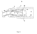
- FIG. 2 Another embodiment of the present invention is in FIG. 2 shown.
- the valve body 11 is located in its various functional positions on the side facing away from the hose section 2 side of the connecting piece 3.
- the connecting device 1 has a sealing device 20, which is formed from a first formed on the connecting piece 3 sealing surface 21 and a second formed on the valve body 11 sealing surface 22.
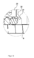
- a detail view of the sealing device 20 is shown in FIG FIG. 3 shown.
- the sealing surfaces 21, 22 are formed and arranged such that they in the closed position of the Valve body 11 abut each other along its circumferential direction in a sealing manner, so that in this position of the valve body 11, a flow from the hose portion to the interior 6 of the housing part and vice versa is prevented.
- the sealing surfaces 21, 22 may be formed so that they occupy an angle of 90 ° to the flow direction S.
- the sealing device 20 is designed as a flat seal. In a closed position, the sealing surfaces 21, 22 are plane-parallel to one another and thus produce the tightness.
- the sealing surfaces 21, 22 may be arranged at an oblique angle to the flow direction S of the fluid, so that the sealing device 20 is designed as a conical seal.
- the sealing surfaces 21, 22 are aligned conically with respect to the flow direction S and enclose an angle of 35 ° with the flow direction.
- the sealing surfaces 21, 22 also come to be plane-parallel to the support when the valve body 11 is transferred into a closed position.
- the sealing surfaces have a circular outer shape.
- a biasing device in particular a spring element may be provided that is in communication with the connecting piece 3 and the valve device 10.
- the biasing element generates a biasing force by which the valve device 10 is pressed onto the connecting piece 3.
- a particularly good fit of the two sealing surfaces 21, 22 are realized on each other and thus the tightness can be further improved.
- Such a biasing member may also be provided in the above-described embodiments of the present invention.
- valve body 11 may be e.g. Be part of a check valve or a double check valve.
- the connecting piece 3 may be formed in particular from a plastic, brass or aluminum or from a brass and / or aluminum alloy.
Landscapes
- Engineering & Computer Science (AREA)
- General Engineering & Computer Science (AREA)
- Mechanical Engineering (AREA)
- Transportation (AREA)
- Quick-Acting Or Multi-Walled Pipe Joints (AREA)
Abstract
Description
- Die Erfindung betrifft eine Anschlussvorrichtung zur Ankopplung eines Schlauchabschnitts an einen Leitungsabschnitt zur Bereitstellung eines Durchflusses eines Mediums von dem Schlauchabschnitts in den Leitungsabschnitt.
- Aus dem allgemeinen Stand der Technik sind derartige Anschlussvorrichtungen bekannt. Z.B. offenbart die
DE 101 62 657 A1 ein Anschlussstück für Fluidleitungen, das zur Einpressmontage in einer Gehäuseausnehmung ausgebildet ist und das einen in die Gehäuseausnehmung einsetzbaren Einsatz aufweist, der ausgebildet ist, um durch Einpressmaßnahmen in der Gehäuseausnehmung fixiert zu werden. Dazu weist der Einsatz zumindest einen hülsenartigen Einsatzkörper sowie an diesem festgelegte, zum Festhalten der anzuschließenden Fluidleitung dienende Haltemittel auf. Zum Fixieren des in die Gehäuseausnehmung eingesetzten Einsatzes ist wenigstens ein separater Befestigungsring vorhanden, der entgegengesetzt zur Einsetzrichtung orientierten Abstützfläche des Einsatzes vorgelagert und zum Einpressen in die Gehäuseausnehmung ausgebildet ist. - Aufgabe der Erfindung ist, eine Anschlussvorrichtung zur Ankopplung eines Schlauchabschnitts an einen Leitungsabschnitt zur Bereitstellung eines Durchflusses eines Mediums bereitzustellen, die möglichst einfach gebaut ist.
- Diese Aufgabe wird mit den Merkmalen des Patentanspruchs 1 gelöst. Weitere Ausführungsformen sind in den auf diesen rückbezogenen Unteransprüchen angegeben.
- Die Erfindung lehrt eine Anschlussvorrichtung zur Ankopplung eines Schlauchabschnitts an einen Leitungsabschnitt zur Bereitstellung eines Durchflusses eines Mediums von dem Schlauchabschnitts in den Leitungsabschnitt, wobei die Anschlussvorrichtung ein Gehäuseteil mit einem Leitungsabschnitt, an das der Schlauch ankoppelbar ist, ein Verbindungsstück mit einer Aufnahmevorrichtung zur Befestigung des Schlauchabschnitts und mit einer Lagerungsvorrichtung zur Verbindung des Verbindungsstück mit dem Gehäuseteil, eine mit dem Gehäuseteil zusammenwirkende Ventilvorrichtung mit einem zwischen einer offenen und einer geschlossenen Stellung bewegbaren Ventilkörper zum Öffnen oder Abdichten des Durchflusses eines Mediums zwischen dem Schlauchabschnitts und dem Gehäuseteil, wobei das Gehäuseteil eine Führungsvorrichtung aufweist, mit der der Ventilkörper in dem Gehäuseteil geführt wird, aufweisen kann. Weiterhin kann das Verbindungsstück eine Dichtungsvorrichtung mit einer dem Ventilkörper zugewandten Dichtfläche aufweisen, und/oder der Ventilkörper eine dem Verbindungsstück zugewandte Dichtfläche aufweisen, wobei die Dichtflächen derart angeordnet sind, dass diese bei der geschlossenen Stellung des Ventilkörpers in dichtender Weise aneinander anliegen.
- Weiterhin kann das Anschlussvorrichtung dadurch gekennzeichnet sein, dass das Verbindungsstück ein Gewinde aufweist, mit dem es in das Gehäuse verschraubbar ist.
- Weiterhin kann die Anschlussvorrichtung dadurch gekennzeichnet sein, dass das Verbindungsstück über einen Bajonett-Verschluss mit dem Gehäuse verbindbar ist.
- Weiterhin kann die Anschlussvorrichtung dadurch gekennzeichnet sein, dass das Verbindungsstück über eine Steckverbindung mit dem Gehäuse verbindbar ist.
- Weiterhin kann die Dichtungsvorrichtung als eine flache Dichtungsvorrichtung ausgebildet sein, wobei die Dichtfläche des Verbindungsstücks und die Dichtfläche des Ventilkörpers einen Winkel zu einer Strömungsrichtung des Fluids, in der das Fluid von dem Schlauchabschnitt in das Gehäuse strömt, einnimmt, und der Winkel in einem Bereich von 85° bis 95°, bevorzugt von 88° bis 92° liegt.
- Weiterhin kann die Dichtungsvorrichtung als eine konische Dichtungsvorrichtung ausgebildet sein, wobei die Dichtfläche des Verbindungsstücks und die Dichtfläche des Ventilkörpers einen Winkel zu einer Strömungsrichtung des Fluids, in der das Fluid von dem Schlauchabschnitt in das Gehäuse (5) strömt, einnimmt, und der Winkel in einem Bereich von 5° bis 80°, bevorzugt von 30° bis 45° liegt.
- Weiterhin kann die Ventilvorrichtung ein Rückschlagventil oder ein Doppelrückschlag-Ventil sein.
- Die Erfindung lehrt in einem weiteren Aspekt ein Bremssystem, für ein Kraftfahrzeug, wobei insbesondere eine hydraulische Flüssigkeit oder ein pneumatisches Gas als Fluid zur Übertragung der Bremskraft von einem Bediener zu mindestens einer fahrzeugseitigen Bremsvorrichtung verwendet wird, dadurch gekennzeichnet, dass eine Anschlussvorrichtung der oben genannten Art zur Verbindung der Schlauchabschnitte von Bremsschläuchen mit dem Gehäuse, insbesondere von Bremsleitungen, vorgesehen ist.
- Durch die erfindungsgemäße Lösung wird eine Anschlussvorrichtung zur Ankopplung eines Schlauchabschnitts an einen Leitungsabschnitt geschaffen, mit der die Funktionalität des Verbindungsstücks, nach der der Schlauchabschnitt an das Gehäuseteil gekoppelt wird, mit der Funktionalität des im Gehäuseteil vorgesehenen Ventils integriert wird. Auf diese Weise wird bei der erfindungsgemäßen Lösung die Zahl der Teile gegenüber aus dem Stand der Technik bekannten Lösungen reduziert. Weiterhin werden durch die Reduktion der Anzahl der Teile auch der Fertigungsaufwand und die Fertigungszeit dann verringert. Darüber hinaus wird durch den konstruktiven Aufbau der Erfindung eine leichte und robuste Anschlussvorrichtung bereitgestellt, die ferner auch den Vorteil bietet, dass einfache Ventile zum Einsatz kommen können, so dass auch der Fertigungsprozess dieser Ventile vereinfacht werden kann.
- Im Folgenden werden Ausführungsbeispiele der Erfindung an Hand der beigefügten Figuren beschrieben, die zeigen:
- ■
Figur 1 eine schematische Schnittdarstellung eines ersten Ausführungsbeispiels der erfindungsgemäßen Anschlussvorrichtung zur Ankopplung eines Schlauchabschnitts, von der ein Verbindungsstück, ein Gehäuseteil und ein Ventilkörper dargestellt ist, - ■
Figur 2 eine schematische Schnittdarstellung eines zweiten Ausführungsbeispiels der erfindungsgemäßen Anschlussvorrichtung zur Ankopplung eines Schlauchabschnitts, von der ebenfalls ein Verbindungsstück, ein Gehäuseteil und ein Ventilkörper dargestellt ist. - ■
Figur 3 eine Detailansicht der schematischen Schnittdarstellung ausFigur 2 - Die
Figur 1 zeigt ein Gehäuseteil 5, das Teil eines Leitungsabschnitts ist, das zur Leitung eines Mediums, also eines Gases oder von Flüssigkeit, vorgesehen ist. Bestimmungsgemäß ist vorgesehen, dass das Medium durch einen Eingang 5a in das Innere 6 des Gehäuseteils 5, oder in eine von dem Gehäuseteil 5 umgrenzten Hohlraum eingeführt wird. Das Medium gelangt über einen Schlauchabschnitt 2, der mittels eines Verbindungsstücks 3 an dem Leitungsabschnitt oder dem Gehäuseteil 5 angekoppelt ist, in das Innere 6 des Gehäuseteils 5, um von dort zu Verbrauchern zu gelangen, die von dem Eingang 5a aus gesehen in Richtung zum Inneren des Gehäuseteils 5, d.h. in einer Strömungsrichtung S gelegen sind, die von dem Schlauchabschnitt 2 aus zum Gehäuseteil 5 führt. - Das Verbindungsstück 3 weist ein Inneres 4 oder einen Hohlraum sowie eine Aufnahmevorrichtung 9 zur Ankopplung des Schlauchabschnitts 2 auf, der an der dem Gehäuseteil 5 abgewandten Seite desselben gelegen ist. Die Aufnahmevorrichtung 9 dient zur Befestigung eines Endes des Schlauchabschnitts 2. Zu diesem Zweck kann die Aufnahmevorrichtung 9 insbesondere eine Klemmvorrichtung aufweisen, mit der der umlaufende Randbereich des Schlauchabschnitts gehalten werden kann. Dabei ist die Aufnahmevorrichtung 9 derart ausgeführt, dass diese den Schlauchabschnitt 2 dichtend in dem Verbindungsstück 3 aufnimmt, so dass das Innere des Schlauchs zusammen mit dem Inneren 4 des Verbindungsstücks 3 gegenüber der Umgebung A abgedichtet ist.
- Das Verbindungsstück 3 weist weiterhin eine Lagerungsvorrichtung 8 auf, mit der das Verbindungsstück 3 an das Gehäuseteil 5 gekoppelt werden kann. Dabei ist das Verbindungsstück 3 fest mit dem Gehäuseteil 5 verbunden, wobei das Verbindungsstück 3 in seiner axialen Richtung und rotatorisch bis zu einer Mindestkraft bzw. Mindestmoment im oder am Gehäuseteil 5 fixiert ist. Die Verbindung ist dabei weiterhin derart gestaltet, so dass die Kombination aus dem Gehäuseteil 5 und dem mit diesem verbundenen Verbindungsstück 3 das Innere 6 des Gehäuseteils 5 sowie das Innere 4 des Verbindungsstücks 3 gegenüber der Umgebung A abdichtet. Hierzu können zwischen dem Verbindungsstück 3 und dem Gehäuseteil 5 Dichtungen angeordnet sein. Das Verbindungsstück 3 kann dabei im Bereich der Lagervorrichtung 8 mit einem Außengewinde und das Gehäuseteil 5 mit einem Innengewinde versehen sein, so dass das Verbindungsstück 3 in das Gehäuseteil 5 verschraubt werden kann.
- In einer weitern, nicht dargestellten Ausführungsform der Erfindung kann das Verbindungsstück 3 eine Steckverbindung aufweisen, zum Verbinden des Verbindungsstück 3 mit dem Gehäuseteil 5. Alternativ hierzu kann das Verbindungsteil 3 mit dem Gehäuse 5 über eine Bajonett-Verbindung verbunden werden.
- Erfindungsgemäß ist weiterhin eine mit dem Gehäuseteil 5 zusammenwirkende Ventilvorrichtung 10 vorgesehen. Die Ventilvorrichtung 10 weist allgemein einen zwischen einer offenen und einer geschlossenen Stellung bewegbaren Ventilkörper 11 zum Öffnen oder Abdichten des Durchflusses des Mediums von dem Schlauchabschnitt 2 zu dem Gehäuseteil 5 und umgekehrt auf. Zur Führung des Ventilkörpers 11 bei seiner Bewegung zwischen der offenen und der geschlossenen Stellung weist das Gehäuseteil 5 eine Führungsvorrichtung 15 auf. Die Führungsvorrichtung 15 ist insbesondere auf einer Anlagefläche gebildet, an der die Außenseite des Ventilkörpers 11 bei den vorgesehenen funktionalen Positionszuständen anliegt und insbesondere formschlüssig anliegt. In einer geschlossenen Stellung der Ventilvorrichtung 10 steht der Ventilkörper 11 mit dem Verbindungsstück 3 in Kontakt, so dass Fluid aus dem Inneren 4 des Verbindungsstück 3 nicht in das Innere 6 des Gehäuseteils 5 strömen kann.
- Eine weitere Ausführungsform der vorliegenden Erfindung ist in
Figur 2 dargestellt. Der Ventilkörper 11 ist in seinem verschiedenen Funktionspositionen auf der zu dem Schlauchabschnitt 2 abgewandten Seite des Verbindungsstücks 3 gelegen. Die Anschlussvorrichtung 1 weist eine Dichtungsvorrichtung 20 auf, die aus einer ersten an dem Verbindungsstück 3 ausgebildeten Dichtfläche 21 und einer zweiten an dem Ventilkörper 11 ausgebildeten Dichtfläche 22 gebildet ist. Eine Detailansicht der Dichtungsvorrichtung 20 ist inFigur 3 dargestellt. Die Dichtflächen 21, 22 sind derart ausgebildet und derart angeordnet, dass diese bei der geschlossenen Stellung des Ventilkörpers 11 entlang ihrer Umfangsrichtung in dichtender Weise aneinander anliegen, so dass in dieser Stellung des Ventilkörpers 11 ein Durchfluss von dem Schlauchabschnitt zu dem Inneren 6 des Gehäuseteils und umgekehrt verhindert wird. - Die Dichtflächen 21, 22 können so ausgebildet sein, dass sie einen Winkel von 90° zur Strömungsrichtung S einnehmen. In diesem Fall ist die Dichtungsvorrichtung 20 als flache Dichtung ausgeführt. In einer geschlossenen Stellung liegen die Dichtflächen 21, 22 planparallel aufeinander und erzeugen so die Dichtigkeit.
- Alternativ hierzu können die Dichtflächen 21, 22 auch in einem schrägen Winkel zur Strömungsrichtung S des Fluids angeordnet sein, so dass die Dichtungsvorrichtung 20 als konische Dichtung ausgeführt ist. In diesem Fall sind die Dichtflächen 21, 22 bezogen auf die Strömungsrichtung S konisch ausgerichtet und schließen mit der Strömungsrichtung einen Winkel von 35° ein. Wie bei der flachen Dichtung kommen auch hier die Dichtflächen 21, 22 planparallel zur Auflage, wenn der Ventilkörper 11 in eine geschlossenen Position überführt wird.
- In beiden genannten Ausführungsformen weisen die Dichtflächen eine kreisrunde äußere Gestalt auf.
- In einer weiteren, nicht dargestellten Ausführungsform der Erfindung kann eine Vorspannvorrichtung, insbesondere ein Federelement vorgesehen sein, dass mit dem Verbindungsstück 3 und dem Ventilvorrichtung 10 in Verbindung steht. Dabei erzeugt das Vorspannelement eine Vorspannkraft, durch die die Ventilvorrichtung 10 auf das Verbindungsstück 3 gepresst wird. Dadurch kann ein besonders guter Sitz der beiden Dichtflächen 21, 22 aufeinander realisiert werden und somit die Dichtigkeit weiter verbessert werden. Ein solches Vorspannelement kann auch in den oben beschriebenen Ausführungsformen der vorliegenden Erfindung vorgesehen werden.
- In den beschriebenen Ausführungsformen kann der Ventilkörper 11 z.B. Teil eines Rückschlagventils oder eines Doppelrückschlag-Ventils sein.
- Dabei kann das Verbindungsstück 3 insbesondere aus einem Kunststoff, aus Messing oder Aluminium oder aus einer Messing- und/oder Aluminiumlegierung gebildet sein.
- Die genannten Merkmale und Ausführungsformen der Erfindung können teilweise oder als Ganzes miteinander kombiniert werden.
Claims (8)
- Anschlussvorrichtung (1) zur Ankopplung eines Schlauchabschnitts (2) an einen Leitungsabschnitt zur Bereitstellung eines Durchflusses eines Mediums von dem Schlauchabschnitts (2) in den Leitungsabschnitt, die Anschlussvorrichtung (1) aufweisend:■ ein Gehäuseteil (5) mit einem Leitungsabschnitt, an das der Schlauch (2) ankoppelbar ist,■ ein Verbindungsstück (3) mit einer Aufnahmevorrichtung (9) zur Befestigung des Schlauchabschnitts (2) und mit einer Lagerungsvorrichtung zur Verbindung des Verbindungsstück (3) mit dem Gehäuseteil (5),■ eine mit dem Gehäuseteil (5) zusammenwirkende Ventilvorrichtung (10) mit einem zwischen einer offenen und einer geschlossenen Stellung bewegbaren Ventilkörper (11) zum Öffnen oder Abdichten des Durchflusses eines Mediums zwischen dem Schlauchabschnitts (2) und dem Gehäuseteil (5), wobei das Gehäuseteil (5) eine Führungsvorrichtung (15) aufweist, mit der der Ventilkörper (11) in dem Gehäuseteil (5) geführt wird,dadurch gekennzeichnet, dass
das Verbindungsstück (3) eine Dichtungsvorrichtung (20) mit einer dem Ventilkörper (11) zugewandten Dichtfläche (21) und dass der Ventilkörper (11) eine dem Verbindungsstück (3) zugewandte Dichtfläche (22) aufweist, die derart angeordnet sind, dass diese bei der geschlossenen Stellung des Ventilkörpers (11) in dichtender Weise aneinander anliegen. - Anschlussvorrichtung nach Anspruch 1, dadurch gekennzeichnet, dass
das Verbindungsstück (3) ein Gewinde aufweist, mit dem es in das Gehäuse (5) verschraubbar ist. - Anschlussvorrichtung nach Anspruch 1, dadurch gekennzeichnet, dass
das Verbindungsstück (3) über einen Bajonett-Verschluss mit dem Gehäuse (5) verbindbar ist. - Anschlussvorrichtung nach Anspruch 1, dadurch gekennzeichnet, dass das Verbindungsstück (3) über eine Steckverbindung mit dem Gehäuse (5) verbindbar ist.
- Anschlussvorrichtung nach einem der Ansprüche 1 bis 4, dadurch gekennzeichnet, dass die Dichtungsvorrichtung (20) als eine flache Dichtungsvorrichtung ausgebildet ist, wobei die Dichtfläche (21) des Verbindungsstücks (3) und die Dichtfläche (22) des Ventilkörpers (11) einen Winkel zur Strömungsrichtung (S) des Fluids, in der das Fluid von dem Schlauchabschnitt (2) in das Gehäuse (5) strömt, einnimmt, und der Winkel in einem Bereich von 85° bis 95°, bevorzugt von 88° bis 92° liegt.
- Anschlussvorrichtung nach einem der Ansprüche 1 bis 4, dadurch gekennzeichnet, dass die Dichtungsvorrichtung (20) eine als konische Dichtungsvorrichtung ausgebildet ist, wobei die Dichtfläche (21) des Verbindungsstücks (3) und die Dichtfläche (22) des Ventilkörpers (11) einen Winkel zu einer Strömungsrichtung (S) des Fluids, in der das Fluid von dem Schlauchabschnitt (2) in das Gehäuse (5) strömt, einnimmt, und der Winkel in einem Bereich von 5° bis 80°, bevorzugt von 30° bis 45° liegt.
- Anschlussvorrichtung nach einem der Ansprüche 1 bis 6, dadurch gekennzeichnet, dass die Ventilvorrichtung (10) ein Rückschlagventil oder ein Doppelrückschlag-Ventils ist.
- Bremssystem, für ein Kraftfahrzeug, wobei insbesondere eine hydraulische Flüssigkeit oder ein pneumatisches Gas als Fluid zur Übertragung der Bremskraft von einem Bediener zu mindestens einer fahrzeugseitigen Bremsvorrichtung verwendet wird,
dadurch gekennzeichnet, dass
eine Anschlussvorrichtung nach einem der Ansprüche 1 bis 4 zur Verbindung der Schlauchabschnitten (2) von Bremsschläuchen mit dem Gehäuse (5), insbesondere von Bremsleitungen, vorgesehen ist.
Applications Claiming Priority (1)
| Application Number | Priority Date | Filing Date | Title |
|---|---|---|---|
| DE102009055819A DE102009055819A1 (de) | 2009-11-25 | 2009-11-25 | Anschlussvorrichtung zur Ankopplung eines Schlauchabschnitts an einen Leitungsabschnitt |
Publications (2)
| Publication Number | Publication Date |
|---|---|
| EP2327917A1 true EP2327917A1 (de) | 2011-06-01 |
| EP2327917B1 EP2327917B1 (de) | 2015-11-11 |
Family
ID=43608309
Family Applications (1)
| Application Number | Title | Priority Date | Filing Date |
|---|---|---|---|
| EP10191997.5A Active EP2327917B1 (de) | 2009-11-25 | 2010-11-22 | Anschlussvorrichtung zur Ankopplung eines Schlauchabschnitts an einen Leitungsabschnitt |
Country Status (3)
| Country | Link |
|---|---|
| EP (1) | EP2327917B1 (de) |
| DE (1) | DE102009055819A1 (de) |
| ES (1) | ES2556339T3 (de) |
Families Citing this family (1)
| Publication number | Priority date | Publication date | Assignee | Title |
|---|---|---|---|---|
| US11732937B2 (en) * | 2021-05-14 | 2023-08-22 | Spectronics Corporation | Multi-profile adapter assembly |
Citations (5)
| Publication number | Priority date | Publication date | Assignee | Title |
|---|---|---|---|---|
| DE587085C (de) * | 1932-05-03 | 1933-10-30 | Ernst Hartmetz | Schlauchkupplung mit beim Kuppeln und Loesen betaetigtem Absperrventil |
| GB1154398A (en) * | 1966-12-17 | 1969-06-04 | Carl Kurt Walther | Hose or Pipe Coupling |
| FR2604237A1 (fr) * | 1986-09-19 | 1988-03-25 | France Materiel Medical | Systeme de raccordement de deux circuits de liquide et application aux dispositifs de dialyse. |
| EP0711946A1 (de) * | 1994-11-12 | 1996-05-15 | Festo KG | Steckkupplung für Leitungen |
| DE10162657A1 (de) | 2001-12-20 | 2003-07-10 | Festo Ag & Co | Anschlussstück für Fluidleitungen sowie damit ausgestattetes fluidtechnisches Gerät |
Family Cites Families (2)
| Publication number | Priority date | Publication date | Assignee | Title |
|---|---|---|---|---|
| US2457052A (en) * | 1946-01-30 | 1948-12-21 | Tecalemit Ltd | Coupling for use in fluid supply systems |
| IT1096845B (it) | 1978-06-30 | 1985-08-26 | Safilo Spa | Procedimento per la produzione di manufatti di resine termoindurenti |
-
2009
- 2009-11-25 DE DE102009055819A patent/DE102009055819A1/de not_active Ceased
-
2010
- 2010-11-22 EP EP10191997.5A patent/EP2327917B1/de active Active
- 2010-11-22 ES ES10191997.5T patent/ES2556339T3/es active Active
Patent Citations (5)
| Publication number | Priority date | Publication date | Assignee | Title |
|---|---|---|---|---|
| DE587085C (de) * | 1932-05-03 | 1933-10-30 | Ernst Hartmetz | Schlauchkupplung mit beim Kuppeln und Loesen betaetigtem Absperrventil |
| GB1154398A (en) * | 1966-12-17 | 1969-06-04 | Carl Kurt Walther | Hose or Pipe Coupling |
| FR2604237A1 (fr) * | 1986-09-19 | 1988-03-25 | France Materiel Medical | Systeme de raccordement de deux circuits de liquide et application aux dispositifs de dialyse. |
| EP0711946A1 (de) * | 1994-11-12 | 1996-05-15 | Festo KG | Steckkupplung für Leitungen |
| DE10162657A1 (de) | 2001-12-20 | 2003-07-10 | Festo Ag & Co | Anschlussstück für Fluidleitungen sowie damit ausgestattetes fluidtechnisches Gerät |
Also Published As
| Publication number | Publication date |
|---|---|
| DE102009055819A1 (de) | 2011-05-26 |
| ES2556339T3 (es) | 2016-01-15 |
| EP2327917B1 (de) | 2015-11-11 |
Similar Documents
| Publication | Publication Date | Title |
|---|---|---|
| EP2527704B1 (de) | Verbinder für eine Fluidleitung und Fluidleitung | |
| EP2707604B1 (de) | Entlüftungsvorrichtung für hydraulische schleifen | |
| EP2333291A1 (de) | Kraftstofftank | |
| DE102016223355A1 (de) | Verbindungsvorrichtung | |
| EP2251582B1 (de) | System zur Trennung von Doppelrohrleitungen | |
| EP2327917B1 (de) | Anschlussvorrichtung zur Ankopplung eines Schlauchabschnitts an einen Leitungsabschnitt | |
| EP2199652B1 (de) | Vorrichtung zum dichten Verbinden und zur Befestigung einer Fluidleitung mit einem anderen fluidführenden Bauteil | |
| DE9315780U1 (de) | Kupplungsnippel | |
| DE102012212752A1 (de) | Gehäuseteil für eine Hochdruckpumpe sowie Hochdruckpumpe | |
| EP1926930A1 (de) | Kupplungseinrichtung zum verbinden von leitungseinrichtungen, vorzugsweise quick connector | |
| DE102010023368A1 (de) | Kopplungselement | |
| DE102013223754A1 (de) | Entlüftungseinrichtung für ein hydraulisches System | |
| WO2018091478A1 (de) | Kupplungsvorrichtung für medienführende leitungen | |
| WO2024042039A1 (de) | Fluidkupplung, verfahren zum herstellen einer fluidkupplung sowie fluidkupplungsanordnung | |
| DE102018117056A1 (de) | Verbindungsanordnung, insbesondere zum Durchführen von wässrigen Harnstofflösungen | |
| DE202011102730U1 (de) | Schwenkverschraubungseinrichtung für Anwendungen in fluidtechnischen Leitungssystemen | |
| DE102009016081B4 (de) | Überstromventil | |
| DE102018112928A1 (de) | Kompaktes Entlüftungsmodul; Betätigungseinrichtung sowie Kupplungssystem | |
| DE202010000872U1 (de) | Vorrichtung zum Verbinden eines Rohres mit einem Anschlussstutzen eines Armaturenanschlusses oder Fittings | |
| EP3719373B1 (de) | Verbindungsanordnung, vorzugsweise für eine fluidleitung eines fahrzeugs | |
| DE102007012536B4 (de) | Leitung mit Knickschutzhülse und Knickschutzhülse | |
| DE102006017257A1 (de) | Blindkupplung mit Rückschlagventil | |
| DE102012100808A1 (de) | Steckverbinder zur Verbindung zweier mediumführender Elemente sowie Rohrleitungssystem mit mindestens zwei mediumführenden Elementen | |
| DE102011118822A1 (de) | Buchse für eine Steckverbindung | |
| DE102011077974A1 (de) | Anschlussstutzen für ein Dosierventil, Dosierventil |
Legal Events
| Date | Code | Title | Description |
|---|---|---|---|
| PUAI | Public reference made under article 153(3) epc to a published international application that has entered the european phase |
Free format text: ORIGINAL CODE: 0009012 |
|
| AK | Designated contracting states |
Kind code of ref document: A1 Designated state(s): AL AT BE BG CH CY CZ DE DK EE ES FI FR GB GR HR HU IE IS IT LI LT LU LV MC MK MT NL NO PL PT RO RS SE SI SK SM TR |
|
| AX | Request for extension of the european patent |
Extension state: BA ME |
|
| 17P | Request for examination filed |
Effective date: 20111201 |
|
| 17Q | First examination report despatched |
Effective date: 20131104 |
|
| REG | Reference to a national code |
Ref country code: DE Ref legal event code: R079 Ref document number: 502010010627 Country of ref document: DE Free format text: PREVIOUS MAIN CLASS: F16L0029020000 Ipc: F16L0033220000 |
|
| GRAP | Despatch of communication of intention to grant a patent |
Free format text: ORIGINAL CODE: EPIDOSNIGR1 |
|
| RIC1 | Information provided on ipc code assigned before grant |
Ipc: F16L 37/38 20060101ALI20150521BHEP Ipc: B60T 17/04 20060101ALI20150521BHEP Ipc: F16L 33/22 20060101AFI20150521BHEP Ipc: F16L 37/092 20060101ALI20150521BHEP |
|
| INTG | Intention to grant announced |
Effective date: 20150619 |
|
| GRAS | Grant fee paid |
Free format text: ORIGINAL CODE: EPIDOSNIGR3 |
|
| GRAA | (expected) grant |
Free format text: ORIGINAL CODE: 0009210 |
|
| AK | Designated contracting states |
Kind code of ref document: B1 Designated state(s): AL AT BE BG CH CY CZ DE DK EE ES FI FR GB GR HR HU IE IS IT LI LT LU LV MC MK MT NL NO PL PT RO RS SE SI SK SM TR |
|
| REG | Reference to a national code |
Ref country code: GB Ref legal event code: FG4D Free format text: NOT ENGLISH |
|
| REG | Reference to a national code |
Ref country code: CH Ref legal event code: EP |
|
| REG | Reference to a national code |
Ref country code: IE Ref legal event code: FG4D Free format text: LANGUAGE OF EP DOCUMENT: GERMAN |
|
| REG | Reference to a national code |
Ref country code: AT Ref legal event code: REF Ref document number: 760644 Country of ref document: AT Kind code of ref document: T Effective date: 20151215 |
|
| REG | Reference to a national code |
Ref country code: DE Ref legal event code: R096 Ref document number: 502010010627 Country of ref document: DE |
|
| REG | Reference to a national code |
Ref country code: FR Ref legal event code: PLFP Year of fee payment: 6 |
|
| REG | Reference to a national code |
Ref country code: ES Ref legal event code: FG2A Ref document number: 2556339 Country of ref document: ES Kind code of ref document: T3 Effective date: 20160115 |
|
| REG | Reference to a national code |
Ref country code: SE Ref legal event code: TRGR |
|
| REG | Reference to a national code |
Ref country code: NL Ref legal event code: FP |
|
| REG | Reference to a national code |
Ref country code: LT Ref legal event code: MG4D |
|
| PG25 | Lapsed in a contracting state [announced via postgrant information from national office to epo] |
Ref country code: NO Free format text: LAPSE BECAUSE OF FAILURE TO SUBMIT A TRANSLATION OF THE DESCRIPTION OR TO PAY THE FEE WITHIN THE PRESCRIBED TIME-LIMIT Effective date: 20160211 Ref country code: IS Free format text: LAPSE BECAUSE OF FAILURE TO SUBMIT A TRANSLATION OF THE DESCRIPTION OR TO PAY THE FEE WITHIN THE PRESCRIBED TIME-LIMIT Effective date: 20160311 Ref country code: HR Free format text: LAPSE BECAUSE OF FAILURE TO SUBMIT A TRANSLATION OF THE DESCRIPTION OR TO PAY THE FEE WITHIN THE PRESCRIBED TIME-LIMIT Effective date: 20151111 Ref country code: LT Free format text: LAPSE BECAUSE OF FAILURE TO SUBMIT A TRANSLATION OF THE DESCRIPTION OR TO PAY THE FEE WITHIN THE PRESCRIBED TIME-LIMIT Effective date: 20151111 |
|
| PG25 | Lapsed in a contracting state [announced via postgrant information from national office to epo] |
Ref country code: PL Free format text: LAPSE BECAUSE OF FAILURE TO SUBMIT A TRANSLATION OF THE DESCRIPTION OR TO PAY THE FEE WITHIN THE PRESCRIBED TIME-LIMIT Effective date: 20151111 Ref country code: FI Free format text: LAPSE BECAUSE OF FAILURE TO SUBMIT A TRANSLATION OF THE DESCRIPTION OR TO PAY THE FEE WITHIN THE PRESCRIBED TIME-LIMIT Effective date: 20151111 Ref country code: RS Free format text: LAPSE BECAUSE OF FAILURE TO SUBMIT A TRANSLATION OF THE DESCRIPTION OR TO PAY THE FEE WITHIN THE PRESCRIBED TIME-LIMIT Effective date: 20151111 Ref country code: PT Free format text: LAPSE BECAUSE OF FAILURE TO SUBMIT A TRANSLATION OF THE DESCRIPTION OR TO PAY THE FEE WITHIN THE PRESCRIBED TIME-LIMIT Effective date: 20160311 Ref country code: BE Free format text: LAPSE BECAUSE OF NON-PAYMENT OF DUE FEES Effective date: 20151130 Ref country code: GR Free format text: LAPSE BECAUSE OF FAILURE TO SUBMIT A TRANSLATION OF THE DESCRIPTION OR TO PAY THE FEE WITHIN THE PRESCRIBED TIME-LIMIT Effective date: 20160212 Ref country code: LV Free format text: LAPSE BECAUSE OF FAILURE TO SUBMIT A TRANSLATION OF THE DESCRIPTION OR TO PAY THE FEE WITHIN THE PRESCRIBED TIME-LIMIT Effective date: 20151111 |
|
| REG | Reference to a national code |
Ref country code: CH Ref legal event code: PL |
|
| PG25 | Lapsed in a contracting state [announced via postgrant information from national office to epo] |
Ref country code: CZ Free format text: LAPSE BECAUSE OF FAILURE TO SUBMIT A TRANSLATION OF THE DESCRIPTION OR TO PAY THE FEE WITHIN THE PRESCRIBED TIME-LIMIT Effective date: 20151111 Ref country code: LI Free format text: LAPSE BECAUSE OF NON-PAYMENT OF DUE FEES Effective date: 20151130 Ref country code: CH Free format text: LAPSE BECAUSE OF NON-PAYMENT OF DUE FEES Effective date: 20151130 |
|
| REG | Reference to a national code |
Ref country code: DE Ref legal event code: R097 Ref document number: 502010010627 Country of ref document: DE |
|
| REG | Reference to a national code |
Ref country code: IE Ref legal event code: MM4A |
|
| PG25 | Lapsed in a contracting state [announced via postgrant information from national office to epo] |
Ref country code: SM Free format text: LAPSE BECAUSE OF FAILURE TO SUBMIT A TRANSLATION OF THE DESCRIPTION OR TO PAY THE FEE WITHIN THE PRESCRIBED TIME-LIMIT Effective date: 20151111 Ref country code: EE Free format text: LAPSE BECAUSE OF FAILURE TO SUBMIT A TRANSLATION OF THE DESCRIPTION OR TO PAY THE FEE WITHIN THE PRESCRIBED TIME-LIMIT Effective date: 20151111 Ref country code: SK Free format text: LAPSE BECAUSE OF FAILURE TO SUBMIT A TRANSLATION OF THE DESCRIPTION OR TO PAY THE FEE WITHIN THE PRESCRIBED TIME-LIMIT Effective date: 20151111 Ref country code: DK Free format text: LAPSE BECAUSE OF FAILURE TO SUBMIT A TRANSLATION OF THE DESCRIPTION OR TO PAY THE FEE WITHIN THE PRESCRIBED TIME-LIMIT Effective date: 20151111 Ref country code: RO Free format text: LAPSE BECAUSE OF FAILURE TO SUBMIT A TRANSLATION OF THE DESCRIPTION OR TO PAY THE FEE WITHIN THE PRESCRIBED TIME-LIMIT Effective date: 20151111 |
|
| PLBE | No opposition filed within time limit |
Free format text: ORIGINAL CODE: 0009261 |
|
| STAA | Information on the status of an ep patent application or granted ep patent |
Free format text: STATUS: NO OPPOSITION FILED WITHIN TIME LIMIT |
|
| PG25 | Lapsed in a contracting state [announced via postgrant information from national office to epo] |
Ref country code: MC Free format text: LAPSE BECAUSE OF FAILURE TO SUBMIT A TRANSLATION OF THE DESCRIPTION OR TO PAY THE FEE WITHIN THE PRESCRIBED TIME-LIMIT Effective date: 20151111 |
|
| 26N | No opposition filed |
Effective date: 20160812 |
|
| PG25 | Lapsed in a contracting state [announced via postgrant information from national office to epo] |
Ref country code: IE Free format text: LAPSE BECAUSE OF NON-PAYMENT OF DUE FEES Effective date: 20151122 |
|
| REG | Reference to a national code |
Ref country code: FR Ref legal event code: PLFP Year of fee payment: 7 |
|
| PG25 | Lapsed in a contracting state [announced via postgrant information from national office to epo] |
Ref country code: SI Free format text: LAPSE BECAUSE OF FAILURE TO SUBMIT A TRANSLATION OF THE DESCRIPTION OR TO PAY THE FEE WITHIN THE PRESCRIBED TIME-LIMIT Effective date: 20151111 |
|
| PG25 | Lapsed in a contracting state [announced via postgrant information from national office to epo] |
Ref country code: BG Free format text: LAPSE BECAUSE OF FAILURE TO SUBMIT A TRANSLATION OF THE DESCRIPTION OR TO PAY THE FEE WITHIN THE PRESCRIBED TIME-LIMIT Effective date: 20151111 Ref country code: HU Free format text: LAPSE BECAUSE OF FAILURE TO SUBMIT A TRANSLATION OF THE DESCRIPTION OR TO PAY THE FEE WITHIN THE PRESCRIBED TIME-LIMIT; INVALID AB INITIO Effective date: 20101122 |
|
| PG25 | Lapsed in a contracting state [announced via postgrant information from national office to epo] |
Ref country code: CY Free format text: LAPSE BECAUSE OF FAILURE TO SUBMIT A TRANSLATION OF THE DESCRIPTION OR TO PAY THE FEE WITHIN THE PRESCRIBED TIME-LIMIT Effective date: 20151111 |
|
| PG25 | Lapsed in a contracting state [announced via postgrant information from national office to epo] |
Ref country code: TR Free format text: LAPSE BECAUSE OF FAILURE TO SUBMIT A TRANSLATION OF THE DESCRIPTION OR TO PAY THE FEE WITHIN THE PRESCRIBED TIME-LIMIT Effective date: 20151111 Ref country code: MT Free format text: LAPSE BECAUSE OF FAILURE TO SUBMIT A TRANSLATION OF THE DESCRIPTION OR TO PAY THE FEE WITHIN THE PRESCRIBED TIME-LIMIT Effective date: 20151111 |
|
| REG | Reference to a national code |
Ref country code: FR Ref legal event code: PLFP Year of fee payment: 8 |
|
| PG25 | Lapsed in a contracting state [announced via postgrant information from national office to epo] |
Ref country code: LU Free format text: LAPSE BECAUSE OF NON-PAYMENT OF DUE FEES Effective date: 20151122 |
|
| PG25 | Lapsed in a contracting state [announced via postgrant information from national office to epo] |
Ref country code: MK Free format text: LAPSE BECAUSE OF FAILURE TO SUBMIT A TRANSLATION OF THE DESCRIPTION OR TO PAY THE FEE WITHIN THE PRESCRIBED TIME-LIMIT Effective date: 20151111 |
|
| PG25 | Lapsed in a contracting state [announced via postgrant information from national office to epo] |
Ref country code: AL Free format text: LAPSE BECAUSE OF FAILURE TO SUBMIT A TRANSLATION OF THE DESCRIPTION OR TO PAY THE FEE WITHIN THE PRESCRIBED TIME-LIMIT Effective date: 20151111 |
|
| P01 | Opt-out of the competence of the unified patent court (upc) registered |
Effective date: 20230530 |
|
| PGFP | Annual fee paid to national office [announced via postgrant information from national office to epo] |
Ref country code: NL Payment date: 20231122 Year of fee payment: 14 |
|
| PGFP | Annual fee paid to national office [announced via postgrant information from national office to epo] |
Ref country code: ES Payment date: 20231215 Year of fee payment: 14 |
|
| PGFP | Annual fee paid to national office [announced via postgrant information from national office to epo] |
Ref country code: AT Payment date: 20231117 Year of fee payment: 14 |
|
| PGFP | Annual fee paid to national office [announced via postgrant information from national office to epo] |
Ref country code: GB Payment date: 20241126 Year of fee payment: 15 |
|
| REG | Reference to a national code |
Ref country code: NL Ref legal event code: MM Effective date: 20241201 |
|
| REG | Reference to a national code |
Ref country code: AT Ref legal event code: MM01 Ref document number: 760644 Country of ref document: AT Kind code of ref document: T Effective date: 20241122 |
|
| PG25 | Lapsed in a contracting state [announced via postgrant information from national office to epo] |
Ref country code: AT Free format text: LAPSE BECAUSE OF NON-PAYMENT OF DUE FEES Effective date: 20241122 |
|
| PG25 | Lapsed in a contracting state [announced via postgrant information from national office to epo] |
Ref country code: NL Free format text: LAPSE BECAUSE OF NON-PAYMENT OF DUE FEES Effective date: 20241201 |
|
| REG | Reference to a national code |
Ref country code: ES Ref legal event code: FD2A Effective date: 20260105 |
|
| PGFP | Annual fee paid to national office [announced via postgrant information from national office to epo] |
Ref country code: DE Payment date: 20251126 Year of fee payment: 16 |
|
| PGFP | Annual fee paid to national office [announced via postgrant information from national office to epo] |
Ref country code: IT Payment date: 20251121 Year of fee payment: 16 |
|
| PGFP | Annual fee paid to national office [announced via postgrant information from national office to epo] |
Ref country code: FR Payment date: 20251124 Year of fee payment: 16 |
|
| PGFP | Annual fee paid to national office [announced via postgrant information from national office to epo] |
Ref country code: SE Payment date: 20251124 Year of fee payment: 16 |
|
| PG25 | Lapsed in a contracting state [announced via postgrant information from national office to epo] |
Ref country code: ES Free format text: LAPSE BECAUSE OF NON-PAYMENT OF DUE FEES Effective date: 20241123 |