EP2326752B1 - Beschichtungsmaske zum elektrolytischen beschichten eines umlaufenden bereiches auf der mantelfläche eines zylinderförmigen körpers - Google Patents
Beschichtungsmaske zum elektrolytischen beschichten eines umlaufenden bereiches auf der mantelfläche eines zylinderförmigen körpers Download PDFInfo
- Publication number
- EP2326752B1 EP2326752B1 EP09776102A EP09776102A EP2326752B1 EP 2326752 B1 EP2326752 B1 EP 2326752B1 EP 09776102 A EP09776102 A EP 09776102A EP 09776102 A EP09776102 A EP 09776102A EP 2326752 B1 EP2326752 B1 EP 2326752B1
- Authority
- EP
- European Patent Office
- Prior art keywords
- coating
- mask
- coating mask
- groove
- piston
- Prior art date
- Legal status (The legal status is an assumption and is not a legal conclusion. Google has not performed a legal analysis and makes no representation as to the accuracy of the status listed.)
- Not-in-force
Links
- 239000011248 coating agent Substances 0.000 title claims description 65
- 238000000576 coating method Methods 0.000 title claims description 65
- 230000002093 peripheral effect Effects 0.000 title claims description 9
- 239000003792 electrolyte Substances 0.000 claims description 15
- 238000007789 sealing Methods 0.000 claims description 9
- 238000002485 combustion reaction Methods 0.000 claims description 3
- 239000000463 material Substances 0.000 claims description 3
- 229920001296 polysiloxane Polymers 0.000 claims description 2
- 239000002184 metal Substances 0.000 claims 1
- 101100269850 Caenorhabditis elegans mask-1 gene Proteins 0.000 description 21
- XEEYBQQBJWHFJM-UHFFFAOYSA-N Iron Chemical compound [Fe] XEEYBQQBJWHFJM-UHFFFAOYSA-N 0.000 description 10
- 238000005266 casting Methods 0.000 description 5
- 229910052742 iron Inorganic materials 0.000 description 5
- 238000004519 manufacturing process Methods 0.000 description 3
- QAOWNCQODCNURD-UHFFFAOYSA-N Sulfuric acid Chemical compound OS(O)(=O)=O QAOWNCQODCNURD-UHFFFAOYSA-N 0.000 description 2
- QAOWNCQODCNURD-UHFFFAOYSA-L Sulfate Chemical compound [O-]S([O-])(=O)=O QAOWNCQODCNURD-UHFFFAOYSA-L 0.000 description 1
- 230000001419 dependent effect Effects 0.000 description 1
- 230000003647 oxidation Effects 0.000 description 1
- 238000007254 oxidation reaction Methods 0.000 description 1
Images

Classifications
-
- F—MECHANICAL ENGINEERING; LIGHTING; HEATING; WEAPONS; BLASTING
- F16—ENGINEERING ELEMENTS AND UNITS; GENERAL MEASURES FOR PRODUCING AND MAINTAINING EFFECTIVE FUNCTIONING OF MACHINES OR INSTALLATIONS; THERMAL INSULATION IN GENERAL
- F16J—PISTONS; CYLINDERS; SEALINGS
- F16J9/00—Piston-rings, e.g. non-metallic piston-rings, seats therefor; Ring sealings of similar construction
- F16J9/26—Piston-rings, e.g. non-metallic piston-rings, seats therefor; Ring sealings of similar construction characterised by the use of particular materials
-
- C—CHEMISTRY; METALLURGY
- C25—ELECTROLYTIC OR ELECTROPHORETIC PROCESSES; APPARATUS THEREFOR
- C25D—PROCESSES FOR THE ELECTROLYTIC OR ELECTROPHORETIC PRODUCTION OF COATINGS; ELECTROFORMING; APPARATUS THEREFOR
- C25D5/00—Electroplating characterised by the process; Pretreatment or after-treatment of workpieces
- C25D5/02—Electroplating of selected surface areas
- C25D5/022—Electroplating of selected surface areas using masking means
-
- C—CHEMISTRY; METALLURGY
- C25—ELECTROLYTIC OR ELECTROPHORETIC PROCESSES; APPARATUS THEREFOR
- C25D—PROCESSES FOR THE ELECTROLYTIC OR ELECTROPHORETIC PRODUCTION OF COATINGS; ELECTROFORMING; APPARATUS THEREFOR
- C25D7/00—Electroplating characterised by the article coated
- C25D7/10—Bearings
Definitions
- the invention relates to a coating mask for the electrolytic coating of a circumferential region on the lateral surface of a cylindrical body according to the preamble of claim 1 and to the use of the coating mask for coating a piston ring groove of a piston for an internal combustion engine according to claim 7.
- the sleeves are offset by a plurality of perpendicular to the piston axis movable pressure rods via an inclined contact surface in motion parallel to the piston axis.
- the coating mask according to the invention consists of an elastically yielding material, this must be done using a simple mechanism only be stretched radially outward to make room for a piston whose piston ring groove to be coated.
- Fig. 1 shows a coating mask 1 in plan view with an inner opening 2 for receiving a cylindrical body, for example a piston 38 (FIG. Fig. 5 ), of which a circumferential region, for example a piston ring groove 39 (FIG. Fig. 5 ), to be coated.
- the coating mask 1 consists of rubber, preferably of silicone, and regularly distributed over its circumference eight axially located openings 3 to 10, the purpose of which, as will be explained in more detail below, is to Dome 11 to 18 of an expansion device 19 (FIGS. Fig. 4 ), with the aid of which the coating mask 1 can be stretched in the direction of the arrows 20 to 23, so that thereby the inner opening 2 is enlarged, after which in the inner opening 2, a piston can be inserted.
- the coating mask 1 has areas 7 to 31 with a thinner wall, which increase the elasticity of the coating mask 1, so that the coating mask 1 can be stretched more easily in the direction of the arrows 20 to.
- Dashed lines are drawn in Fig. 1 a ring line 32, which can be led to an electrolyte via an inlet channel 33. Via supply channels 34, 35, 36 ... the electrolyte then passes into a circumferential coating groove 37, which, as Fig. 5 shows is closed by the piston ring groove 39 of a piston 38 to be coated. Subsequently, the electrolyte is discharged via a discharge channel 40 from the coating mask 1.
- FIGS. 2 and 3 are cuts along the line AA in Fig. 1 and show that the coating mask 1 has two ring lines 32 and 32 ', arranged one behind the other in the axial direction, which are each connected to the coating groove 37 via supply channels 35 and 35' distributed uniformly around the circumference.
- the inner opening 2 has in this case starting from the centrally located coating groove 37 a funnel-shaped widening in both axial directions form.
- the electrolyte passes via the inlet channel 33 into the lower ring line 32 ', flows via the lower feed channels 35' in the closed from the piston to be coated coating groove 37, from here via the upper feed channels 35 in the upper ring line 32, and is from here about the drainage channel 40 discharged from the coating mask 1.
- the outlets 41 of the feed channels 35, 35 'in the coating groove 37th are also recognized in the FIGS. 2 and 3 also the outlets 41 of the feed channels 35, 35 'in the coating groove 37th
- ring electrodes 42 and 43 arranged with schematically indicated electrical connections 53 and 54.
- the present coating mask 1 can be used to electrolytically coat the flanks of the piston ring groove 39 of the piston 38 with, for example, iron.
- the ring electrodes 42 and 43 are connected as anodes, that is, connected via the terminals 53 and 54 to the positive pole of a DC voltage source
- the piston 38 is connected as a cathode, that is, connected to the negative pole of the DC voltage source
- the coating mask 1 can also be used to anodically oxidize the flanks of the piston ring groove 39 of the piston 38.
- the piston 38 is connected as an anode, that is, connected to the positive pole of a DC voltage source
- the ring electrodes 42 and 43 are connected as cathodes, ie, connected via the terminals 53 and 54 to the negative pole of a DC voltage source, and is used as an electrolyte, for example Sulfuric acid supplied via the inlet channel 33 of the coating mask 1.
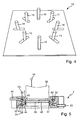
- the coating mask 1 is first of all applied via its openings 3 to 9 to the domes 11 to 18 of the stretching device 19 Fig. 4 pushed. Subsequently, the domes 11 to 18 are displaced radially outward, so that the coating mask 1 is stretched in the direction of the arrows 20 to 23. Now, the piston 38 is inserted into the thereby extended, inner opening 2, after which the domes 11 to 18 are moved so far radially inward until the sealing lips 44 and 45, of which the coating groove 37 is limited, according to Fig. 5 Both sides of the piston ring groove 39 to be coated on the lateral surface of the body, here on the ring portion 48 of the piston 38, come to rest and thus hermetically seal the coating groove 37 and the piston ring groove 39 of the piston 38 to be coated.
- the flanks of Kolbenringnut 39 of the piston 38 are coated sufficiently, so that after the electrolyte has been discharged completely from the ring lines 32 and 32 ', the ring lines 32 and 32' and the coating groove 37 with hot hot steam at 130 ° C. be rinsed. Subsequently, the domes 11 to 18 of the stretching device 19 are moved radially outward, so that Also, the diameter of the inner opening 2 is increased and the piston 38 can be removed from the coating mask 1.
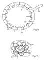
- the coating mask 1 is produced in the casting process, wherein initially in a mold 49, as in Fig. 7 is shown, two loop templates 50 are inserted, which consist of sintered plastic, and of which a in Fig. 6 is shown.
- the loop template 50 according to Fig. 6 allows the inlet channel 33 and feed channels 34, 35, 36, ... recognize.
- the mold 49 according to Fig. 7 are the feed channels 34 to 36 in conjunction with a G demkem 51, which ensures by its special shape that during the casting process, the inner opening 2 and the coating groove 37 are completely formed.
- the ring line templates 50 remain after the casting process in the coating mask 1 and have predetermined breaking points 52, which in the first coating operation, when the coating mask 1 and thus the ring line template 50 are stretched radially outwardly for the first time, so that thereby the elasticity of the coating mask. 1 not hindered. It is advantageous to incorporate in the production of the ring line templates 50 each have a ring electrode in the ring line templates 50 with.
Landscapes
- Engineering & Computer Science (AREA)
- Chemical & Material Sciences (AREA)
- General Engineering & Computer Science (AREA)
- Chemical Kinetics & Catalysis (AREA)
- Electrochemistry (AREA)
- Materials Engineering (AREA)
- Metallurgy (AREA)
- Organic Chemistry (AREA)
- Mechanical Engineering (AREA)
- Electroplating Methods And Accessories (AREA)
- Printing Plates And Materials Therefor (AREA)
- Pistons, Piston Rings, And Cylinders (AREA)
Description
- Die Erfindung betrifft eine Beschichtungsmaske zum elektrolytischen Beschichten eines umlaufenden Bereiches auf der Mantelfläche eines zylinderförmigen Körpers nach dem Oberbegriff des Anspruches 1 und die Verwendung der Beschichtungsmaske zur Beschichtung einer Kolbenringnut eines Kolbens für einen Verbrennungsmotor nach Anspruch 7.
- Aus der Patentschrift
US 6 821 408 ist eine Vorrichtung zur anodischen Oxydation eines umlaufenden Bereiches auf der Mantelfläche eines zylindrischen Körpers, insbesondere der Kolbenringnut eines Kolbens für einen Verbrennungsmotor bekannt, wobei der zu beschichtende Bereich beidseitig von zwei umlaufenden und zunächst im Schnitt runden Dichtringen dadurch hermetisch abgedichtet wird, dass auf die Dichtringe von je einer Hülse Druck ausgeübt wird, bis sich die Dichtringe oval verformen, wobei diese Ovalität senkrecht zur Mantelfläche des Kolbens ausgerichtet ist. Hierdurch gelangen die Dichtringe zur Anlage an die Mantelfläche beidseitig der Kolbenringnut und verschließen diesen Bereich hermetisch. Anschließend wird ein Elektrolyt in diesen Bereich eingeleitet und die darin befindliche Kolbenringnut anodisch oxidiert. Nachteilig ist, dass ein sehr komplizierter Mechanismus zur Verformung der Dichtringe erforderlich ist. Hierbei werden die Hülsen von mehreren senkrecht zur Kolbenachse beweglichen Druckstangen über eine schräge Kontaktfläche in Bewegung parallel zur Kolbenachse versetzt. - Diesen Nachteil des Standes der Technik zu vermeiden ist Aufgabe der Erfindung. Gelöst wird diese Aufgabe mit den im Kennzeichen des Hauptanspruches stehenden Merkmalen. Zweckmäßige Ausgestaltungen der Erfindung sind Gegenstand der Unteransprüche.
- Da die Beschichtungsmaske gemäß der Erfindung aus einem elastisch nachgiebigen Material besteht, muss diese unter Verwendung eines einfachen Mechanismus nur nach radial außen gedehnt werden, um Platz für einen Kolben zu machen, dessen Kolbenringnut beschichtet werden soll.
- Die Erfindung wird im Folgenden anhand der Zeichnungen beschrieben. Es zeigen
- Fig. 1
- eine Draufsicht auf eine Beschichtungsmaske für Kolbenringnuten, in die eine Ringleitung für einen Elektrolyten gestrichelt eingezeichnet ist,
- Fig. 2
- einen Schnitt durch die Beschichtungsmaske entlang der Linie AA in
Fig. 1 , - Fig. 3
- einen vergrößerten Ausschnitt des in
Fig. 2 dargestellten Schnittbildes, - Fig. 4
- eine perspektivische Darstellung einer Dehnvorrichtung, mit deren Hilfe die Beschichtungsmaske nach radial außer gedehnt wird, um einen Kolben einführen zu können,
- Fig. 5
- einen Schnitt durch die Beschichtungsmaske mit eingeführtem Kolben, dessen erste Kolbenringnut beschichtet wird,
- Fig. 6
- eine Ringleitungsschablone zur Herstellung der Ringleitung und
- Fig. 7
- eine Gießform mit eingelegter Ringleitungsschablone zur gießtechnischen Herstellung der Beschichtungsmaske.
-
Fig. 1 zeigt eine Beschichtungsmaske 1 in Draufsicht mit einer inneren Öffnung 2 zur Aufnahme eines zylinderförmigen Körpers, beispielsweise eines Kolbens 38 (Fig. 5 ), von dem ein umlaufender Bereich, beispielsweise eine Kolbenringnut 39 (Fig. 5 ), beschichtet werden soll. Die Beschichtungsmaske 1 besteht aus Kautschuk, vorzugsweise aus Silikon, und weist regelmäßig über ihren Umfang verteilt acht axial liegende Öffnungen 3 bis 10 auf, deren Zweck, wie weiter unten näher erläutert wird, darin besteht, Dome 11 bis 18 einer Dehnvorrichtung 19 (Fig. 4 ) aufzunehmen, mit deren Hilfe die Beschichtungsmaske 1 in Richtung der Pfeile 20 bis 23 gedehnt werden kann, sodass hierdurch auch die innere Öffnung 2 vergrößert wird, wonach in die innere Öffnung 2 ein Kolben eingeführt werden kann. - Zwischen den Öffnungen 3 bis 10 weist die Beschichtungsmaske 1 Bereiche 24 bis 31 mit dünnerer Wandung auf, die die Elastizität der Beschichtungsmaske 1 erhöhen, sodass die Beschichtungsmaske 1 leichter in Richtung der Pfeile 20 bis 23 gedehnt werden kann.
- Gestrichelt eingezeichnet ist in
Fig. 1 eine Ringleitung 32, der über einen Zulaufkanal 33 ein Elektrolyt zu geführt werden kann. Über Zuführungskanäle 34, 35, 36 ... gelangt der Elektrolyt dann in eine umlaufende Beschichtungsnut 37, die, wieFig. 5 zeigt, von der Kolbenringnut 39 eines Kolbens 38, die beschichtet werden soll, verschlossen wird. Anschließend wird der Elektrolyt über einen Ablaufkanal 40 aus der Beschichtungsmaske 1 abgeleitet. - Die
Figuren 2 und 3 sind Schnitte entlang der Linie AA inFig. 1 und zeigen, dass die Beschichtungsmaske 1 zwei in axialer Richtung hintereinander angeordnete Ringleitungen 32 und 32' aufweist, die jeweils über gleichmäßig über den Umfang verteilte Zuführungskanäle 35 und 35' mit der Beschichtungsnut 37 verbunden sind. Die innere Öffnung 2 hat hierbei ausgehend von der zentral liegenden Beschichtungsnut 37 eine in beide axiale Richtungen trichterförmig sich erweiternde Form. - Hierbei gelangt der Elektrolyt über den Zulaufkanal 33 in die untere Ringleitung 32', fließt über die unteren Zuführungskanäle 35' in die vom zu beschichtenden Kolben verschlossene Beschichtungsnut 37, von hier über die oberen Zuführungskanäle 35 in die obere Ringleitung 32, und wird von hier über den Ablaufkanal 40 aus der Beschichtungsmaske 1 ausgeleitet. Zu erkennen sind in den
Figuren 2 und 3 auch die Austritte 41 der Zuführungskanäle 35, 35' in die Beschichtungsnut 37. - In den Ringleitungen 32, 32' sind, wie in
Fig. 2 und 3 gut erkennbar ist, Ringelektroden 42 und 43 mit schematisch angedeuteten elektrischen Anschlüssen 53 und 54 angeordnet. Die vorliegende Beschichtungsmaske 1 kann dazu verwendet werden, die Flanken der Kolbenringnut 39 des Kolbens 38 elektrolytisch beispielsweise mit Eisen zu beschichten. Hierzu werden die Ringelektroden 42 und 43 als Anoden geschaltet, d.h., über die Anschlüsse 53 und 54 an den Pluspol einer Gleichspannungsquelle angeschlossen, wird der Kolben 38 als Kathode geschaltet, d.h., an den Minuspol der Gleichspannungsquelle angeschlossen, und wird ein eisenhaltiger Elektrolyt, beispielsweise eine Eisenlösung auf Sulfatbasis, über den Zulaufkanal 33 in die Beschichtungsmaske 1 eingeleitet. - Die Beschichtungsmaske 1 kann aber auch dazu verwendet werden, die Flanken der Kolbenringnut 39 des Kolbens 38 anodisch zu oxidieren. Hierzu wird der Kolben 38 als Anode geschaltet, d.h., an den positiven Pol einer Gleichspannungsquelle angeschlossen, werden die Ringelektroden 42 und 43 als Kathoden geschaltet, d.h., über die Anschlüsse 53 und 54 an den negativen Pol einer Gleichspannungsquelle angeschlossen, und wird als Elektrolyt beispielsweise Schwefelsäure über den Zulaufkanal 33 der Beschichtungsmaske 1 zugeführt.
- Soll die Kolbenringnut 39 eines Kolbens 38 beschichtet werden, wird zunächst die Beschichtungsmaske 1 über ihre Öffnungen 3 bis 9 auf die Domen 11 bis 18 der Dehnvorrichtung 19 gemäß
Fig. 4 geschoben. Anschließend werde die Domen 11 bis 18 nach radial außen verschoben, sodass die Beschichtungsmaske 1 in Richtung der Pfeile 20 bis 23 gedehnt wird. Nun wird der Kolben 38 in die hierdurch erweiterte, innere Öffnung 2 eingeführt, wonach die Domen 11 bis 18 so weit nach radial innen bewegt werden, bis die Dichtlippen 44 und 45, von denen die Beschichtungsnut 37 begrenzt wird, gemäßFig. 5 beidseitig der zu beschichtenden Kolbenringnut 39 an der Mantelfläche des Körpers, hier an der Ringpartie 48 des Kolbens 38, zur Anlage gelangen und damit die Beschichtungsnut 37 und die zu beschichtende Kolbenringnut 39 des Kolbens 38 hermetisch verschließen. - Anschließend wird, falls die Flanken der Kolbenringnut 39 mit Eisen beschichtet werden sollen, ein eisenhaltiger Elektrolyt über den Zulaufkanal 33 in die Beschichtungsmaske 1 eingeleitet, werden die Ringelektroden 42 und 43 über die elektrischen Anschlüsse 53 und 54 an den Pluspol einer Gleichspannungsquelle angeschlossen, wird der Kolben 38 über einen elektrischen Anschluss 55 an den Minuspol der Gleichspannungsquelle angeschlossen und wird der überschüssige Elektrolyt über den Ablaufkanal 40 aus der Beschichtungsmaske 1 abgeleitet.
- Nach einer gewissen Zeit sind die Flanken der Kolbenringnut 39 des Kolbens 38 in ausreichendem Maße beschichtet, sodass, nachdem der Elektrolyt komplett aus der Ringleitungen 32 und 32' ausgeleitet wurde, die Ringleitungen 32 und 32' und die Beschichtungsnut 37 mit 130 °C heißen Heißdampf gespült werden. Anschließend werden die Domen 11 bis 18 der Dehnvorrichtung 19 nach radial außen bewegt, sodass auch der Durchmesser der inneren Öffnung 2 vergrößert wird und der Kolben 38 aus der Beschichtungsmaske 1 entnommen werden kann.
- Hergestellt wird die Beschichtungsmaske 1 im Gießverfahren, wobei zunächst in eine Gießform 49, wie sie in
Fig. 7 dargestellt ist, zwei Ringleitungsschablonen 50 eingelegt werden, die aus Sinterkunststoff bestehen, und von denen eine inFig. 6 dargestellt ist. Die Ringleitungsschablone 50 gemäßFig. 6 lässt den Zulaufkanal 33 und Zuführungskanäle 34, 35, 36, ... erkennen. In der Gießform 49 gemäßFig. 7 stehen die Zuführungskanäle 34 bis 36 in Verbindung mit einem Gießkem 51, der durch seine spezielle Form gewährleistet, dass beim Gießvorgang die innere Öffnung 2 und die Beschichtungsnut 37 vollständig ausgebildet werden. - Die Ringleitungsschablonen 50 verbleiben nach dem Gießvorgang in der Beschichtungsmaske 1 und weisen Sollbruchstellen 52 auf, die beim ersten Beschichtungsvorgang, wenn die Beschichtungsmaske 1 und damit auch die Ringleitungsschablone 50 das erste Mal nach radial außen gedehnt werden, aufbrechen, sodass hierdurch die Elastizität der Beschichtungsmaske 1 nicht behindert wird. Vorteilhaft ist, bei der Herstellung der Ringleitungsschablonen 50 jeweils eine Ringelektrode in die Ringleitungsschablonen 50 mit einzubauen.
-
- 1
- Beschichtungsmaske
- 2
- innere Öffnung
- 3 bis 10
- Öffnung
- 11 bis 18
- Dom
- 19
- Dehnvorrichtung
- 20 bis 23
- Pfeil
- 24 bis 31
- Bereich
- 32, 32'
- Ringleitung
- 33
- Zulaufkanal
- 34 bis 36
- Zuführungskanal
- 37
- Beschichtungsnut
- 38
- Kolben, zylinderförmiger Körper, Körper
- 39
- Kolbenringnut des Kolbens 38, umlaufender Bereich
- 40
- Ablaufkanal
- 41
- Austritt
- 42, 43
- Elektrode, Ringelektrode
- 44, 45
- Dichtlippe
- 48
- Ringpartie des Kolbens 38, Mantelfläche des Körpers
- 49
- Gießform
- 50
- Ringleitungsschablone
- 51
- Gießkem
- 52
- Sollbruchstelle
- 53,54,55
- elektrischer Anschluss
Claims (7)
- Beschichtungsmaske (1) zum elektrolytischen Beschichten eines umlaufenden Bereiches (39) auf der Mantelfläche (48) eines im Wesentlichen zylinderförmigen Körpers (38) aus Metall- mit einer innere Öffnung (2), deren Durchmesser zumindest näherungsweise gleich dem Durchmesser des Körpers (38) ist,- mit zwei in der inneren Öffnung (2) angeordneten, umlaufenden und eine Beschichtungsnut (37) beidseitig begrenzenden Dichtlippen (44, 45) aus elastisch nachgiebigem Material, die beidseitig des umlaufenden Bereiches (39) an den Körper (38) in Anlage bringbar sind und dann die auf dem umlaufenden Bereich (39) anliegende Beschichtungsnut (37) hermetisch abschließen, sodass ein Elektrolyt durch die Beschichtungsnut (37) hindurchleitbar ist, und- mit mindestens einer, mit dem Elektrolyten in Kontakt befindlichen Elektrode (42, 43), die an den Pol einer Gleichspannungsquelle anschließbar ist,dadurch gekennzeichnet,
dass die Beschichtungsmaske (1) aus einem elastisch nachgiebigen Material besteht und gleichmäßig über den Umfang verteilte, axial liegende Öffnungen (3 bis 10) aufweist, in die Domen (11 bis 18) einer Dehnvorrichtung (19) einführbar sind, die insoweit beweglich gelagert sind, dass von der Dehnvorrichtung (19) der radiale Durchmesser der Beschichtungsmaske (1) und damit der inneren Öffnung (2) insoweit vergrößerbar ist, dass der zylinderförmige Körper (38) in die innere Öffnung (2) einführbar ist, wobei der radiale Durchmesser der Beschichtungsmaske (1) so gewählt ist, dass nach einer Verkleinerung des radialen Durchmessers der Beschichtungsmaske (1) und damit der Inneren Öffnung (2) die elastisch vorgespannte Beschichtungsmaske (1) die Dichtlippen (44, 45) der Beschichtungsnut (37) beidseitig des umlaufenden Bereiches (39) auf den Körper (38) presst. - Beschichtungsmaske (1) nach Anspruch 1, dadurch gekennzeichnet, dass sie aus Kautschuk besteht.
- Beschichtungsmaske (1) nach Anspruch 1, dadurch gekennzeichnet, dass sie aus Silikon besteht.
- Beschichtungsmaske (1) nach einem der Ansprüche 1 bis 3, dadurch gekennzeichnet, dass sie zwischen den Öffnungen (3 bis 10) Bereiche (24 bis 31) mit gegenüber der Wandung in den Bereichen der Öffnungen (3 bis 10) dünnerer Wandung aufweist.
- Beschichtungsmaske (1) nach einem der vorhergehenden Ansprüche, dadurch gekennzeichnet, dass sie zwischen der Beschichtungsnut (37) und den Öffnungen (3 bis 30) mindestens eine umlaufende Ringleitung (32) aufweist, die über Zuführungskanäle (34, 35, 36) mit der Beschichtungsnut (37) verbunden ist, und die mit einem Zulaufkanal (33) zum Zuführen des Elektrolyten und mit einem Ablaufkanal (40) zum Ausleiten des Elektrolyten verbunden ist.
- Beschichtungsmaske (1) nach Anspruch 5, dadurch gekennzeichnet, dass die Elektrode (42, 43) als umlaufende Ringelektrode ausgebildet und im Innern der Ringleitung (32) angeordnet ist.
- Verwendung der Beschichtungsmaske (1) nach einem der vorhergehenden Ansprüche zur Beschichtung einer Kolbenringnut (39) eines Kolbens (38) für einen Verbrennungsmotor.
Applications Claiming Priority (2)
| Application Number | Priority Date | Filing Date | Title |
|---|---|---|---|
| DE102008038323A DE102008038323A1 (de) | 2008-08-19 | 2008-08-19 | Beschichtungsmaske zum elektrolytischen Beschichten eines umlaufenden Bereiches auf der Mantelfläche eines zylinderförmigen Körpers |
| PCT/DE2009/001167 WO2010020235A2 (de) | 2008-08-19 | 2009-08-19 | Beschichtungsmaske zum elektrolytischen beschichten eines umlaufenden bereiches auf der mantelfläche eines zylinderförmigen körpers |
Publications (2)
| Publication Number | Publication Date |
|---|---|
| EP2326752A2 EP2326752A2 (de) | 2011-06-01 |
| EP2326752B1 true EP2326752B1 (de) | 2012-10-17 |
Family
ID=41566553
Family Applications (1)
| Application Number | Title | Priority Date | Filing Date |
|---|---|---|---|
| EP09776102A Not-in-force EP2326752B1 (de) | 2008-08-19 | 2009-08-19 | Beschichtungsmaske zum elektrolytischen beschichten eines umlaufenden bereiches auf der mantelfläche eines zylinderförmigen körpers |
Country Status (8)
| Country | Link |
|---|---|
| US (1) | US8864966B2 (de) |
| EP (1) | EP2326752B1 (de) |
| JP (1) | JP3170666U (de) |
| KR (1) | KR101626633B1 (de) |
| CN (1) | CN202039140U (de) |
| BR (1) | BRPI0917367A2 (de) |
| DE (1) | DE102008038323A1 (de) |
| WO (1) | WO2010020235A2 (de) |
Families Citing this family (3)
| Publication number | Priority date | Publication date | Assignee | Title |
|---|---|---|---|---|
| DE102015222862A1 (de) | 2015-11-19 | 2017-05-24 | Mahle International Gmbh | Verfahren zum Beschichten wenigstens einer an einem Kolben vorgesehenen Kolbennut mit einer Schutzbeschichtung und Beschichtungseinrichtung, insbesondere zur Durchführung des Verfahrens |
| JP6371354B2 (ja) * | 2016-09-30 | 2018-08-08 | 本田技研工業株式会社 | 被膜形成装置 |
| CN111501028A (zh) * | 2020-04-30 | 2020-08-07 | 中国航发哈尔滨东安发动机有限公司 | 一种具有密封结构的防护方法及密封防护工装 |
Family Cites Families (5)
| Publication number | Priority date | Publication date | Assignee | Title |
|---|---|---|---|---|
| JPS5521502A (en) * | 1978-07-25 | 1980-02-15 | Sumitomo Metal Mining Co Ltd | Method and device for partial plating |
| JPS6473080A (en) * | 1987-09-11 | 1989-03-17 | Honda Motor Co Ltd | Jig for surface treatment of piston for internal combustion engine |
| JP2001073080A (ja) * | 1999-08-31 | 2001-03-21 | Nippon Steel Corp | 遅れ破壊特性の優れた高張力鋼材及びその製造方法 |
| JP3934891B2 (ja) | 2001-01-15 | 2007-06-20 | 株式会社日立製作所 | 陽極酸化処理方法および装置 |
| DE102006020593A1 (de) * | 2006-05-02 | 2007-11-15 | Mahle International Gmbh | Maske zum galvanischen Beschichten der Außenfläche eines aus einem elektrisch leitfähigen Material bestehenden Körpers und Verfahren zur Herstellung der Maske |
-
2008
- 2008-08-19 DE DE102008038323A patent/DE102008038323A1/de not_active Withdrawn
-
2009
- 2009-08-19 US US12/737,785 patent/US8864966B2/en not_active Expired - Fee Related
- 2009-08-19 EP EP09776102A patent/EP2326752B1/de not_active Not-in-force
- 2009-08-19 WO PCT/DE2009/001167 patent/WO2010020235A2/de not_active Ceased
- 2009-08-19 JP JP2011600028U patent/JP3170666U/ja not_active Expired - Fee Related
- 2009-08-19 BR BRPI0917367A patent/BRPI0917367A2/pt not_active Application Discontinuation
- 2009-08-19 CN CN200990100432.2U patent/CN202039140U/zh not_active Expired - Lifetime
- 2009-08-19 KR KR1020117003774A patent/KR101626633B1/ko not_active Expired - Fee Related
Also Published As
| Publication number | Publication date |
|---|---|
| EP2326752A2 (de) | 2011-06-01 |
| WO2010020235A3 (de) | 2010-06-10 |
| JP3170666U (ja) | 2011-09-29 |
| US20120085654A1 (en) | 2012-04-12 |
| KR101626633B1 (ko) | 2016-06-01 |
| US8864966B2 (en) | 2014-10-21 |
| KR20110049804A (ko) | 2011-05-12 |
| DE102008038323A1 (de) | 2010-02-25 |
| WO2010020235A2 (de) | 2010-02-25 |
| BRPI0917367A2 (pt) | 2015-11-17 |
| CN202039140U (zh) | 2011-11-16 |
Similar Documents
| Publication | Publication Date | Title |
|---|---|---|
| DE3342742C2 (de) | Verfahren zur Herstellung von Kontaktfederbuchsen | |
| DE10122238B4 (de) | Bildübertragungstrommel für Dokumentendrucker/-kopierer | |
| DE1675212A1 (de) | Dichtungsring | |
| DE7220093U (de) | Kupplungshülse zum Verbinden von elektrischen Leitern | |
| DE19846041A1 (de) | Membranmodul | |
| DE2601065C2 (de) | Elektrolysevorrichtung | |
| DE112007003022T5 (de) | Folien- oder Filmbildungswalze, Folien- oder Filmformvorrichtung und Miniaturmusterübertragungsvorrichtung | |
| WO2010020235A2 (de) | Beschichtungsmaske zum elektrolytischen beschichten eines umlaufenden bereiches auf der mantelfläche eines zylinderförmigen körpers | |
| DE2557416A1 (de) | Verfahren und vorrichtung zum herstellen eines rohrverbinders mit radialer erweiterung | |
| EP0649689A1 (de) | Verfahren und Vorrichtung zur Herstellung von Pressfittings | |
| AT409945B (de) | Verfahren zum herstellen einer rohrendmuffe aus thermoplastischem kunststoff | |
| DE102011106655A1 (de) | Verfahren zur Herstellung eines Kolbens für einen Verbrennungsmotor | |
| EP2374527B1 (de) | Begasungseinrichtung zum intermittierenden Einbringen eines Gases in eine Flüssigkeit | |
| WO2016139194A1 (de) | Radialpresse | |
| DE102010048761B4 (de) | Verfahren zum Fertigen einer Bipolarplatte für einen Brennstoffzellenstapel und Bipolarplatte | |
| DE102011054773A1 (de) | Anschlusspol für einen Akkumulator, Akkumulatorgehäuse und Maschine zur Herstellung eines Anschlusspols | |
| EP3005446B1 (de) | Verschlussstopfenanordnung, gehäuse eines akkumulators und akkumulator | |
| DE2804645A1 (de) | Rohrkupplung | |
| DE10349917A1 (de) | Dicht-, Abstreif- und Führungselement für die Kolbenstange von Pneumatikzylindern | |
| DE102010019409A1 (de) | Gesenkelement | |
| DE102016210331A1 (de) | Kegelrollenlager und Verfahren zu seiner Herstellung | |
| EP1422429B1 (de) | Kugelgelenk | |
| DE102013225333A1 (de) | Nachgeschmierte Lageranordnung | |
| DE20216045U1 (de) | Abdichtung für ein Kugelgelenk | |
| DE202011103277U1 (de) | Anschlusspol für einen Akkumulator, Akkumulatorgehäuse und Maschine zur Herstellung eines Anschlusspols |
Legal Events
| Date | Code | Title | Description |
|---|---|---|---|
| PUAI | Public reference made under article 153(3) epc to a published international application that has entered the european phase |
Free format text: ORIGINAL CODE: 0009012 |
|
| 17P | Request for examination filed |
Effective date: 20110311 |
|
| AK | Designated contracting states |
Kind code of ref document: A2 Designated state(s): AT BE BG CH CY CZ DE DK EE ES FI FR GB GR HR HU IE IS IT LI LT LU LV MC MK MT NL NO PL PT RO SE SI SK SM TR |
|
| AX | Request for extension of the european patent |
Extension state: AL BA RS |
|
| DAX | Request for extension of the european patent (deleted) | ||
| GRAP | Despatch of communication of intention to grant a patent |
Free format text: ORIGINAL CODE: EPIDOSNIGR1 |
|
| GRAS | Grant fee paid |
Free format text: ORIGINAL CODE: EPIDOSNIGR3 |
|
| GRAA | (expected) grant |
Free format text: ORIGINAL CODE: 0009210 |
|
| AK | Designated contracting states |
Kind code of ref document: B1 Designated state(s): AT BE BG CH CY CZ DE DK EE ES FI FR GB GR HR HU IE IS IT LI LT LU LV MC MK MT NL NO PL PT RO SE SI SK SM TR |
|
| REG | Reference to a national code |
Ref country code: GB Ref legal event code: FG4D Free format text: NOT ENGLISH |
|
| REG | Reference to a national code |
Ref country code: CH Ref legal event code: EP |
|
| REG | Reference to a national code |
Ref country code: IE Ref legal event code: FG4D Free format text: LANGUAGE OF EP DOCUMENT: GERMAN |
|
| REG | Reference to a national code |
Ref country code: AT Ref legal event code: REF Ref document number: 579967 Country of ref document: AT Kind code of ref document: T Effective date: 20121115 |
|
| REG | Reference to a national code |
Ref country code: DE Ref legal event code: R096 Ref document number: 502009005130 Country of ref document: DE Effective date: 20121213 |
|
| REG | Reference to a national code |
Ref country code: NL Ref legal event code: VDEP Effective date: 20121017 |
|
| REG | Reference to a national code |
Ref country code: LT Ref legal event code: MG4D |
|
| PG25 | Lapsed in a contracting state [announced via postgrant information from national office to epo] |
Ref country code: HR Free format text: LAPSE BECAUSE OF FAILURE TO SUBMIT A TRANSLATION OF THE DESCRIPTION OR TO PAY THE FEE WITHIN THE PRESCRIBED TIME-LIMIT Effective date: 20121017 Ref country code: LT Free format text: LAPSE BECAUSE OF FAILURE TO SUBMIT A TRANSLATION OF THE DESCRIPTION OR TO PAY THE FEE WITHIN THE PRESCRIBED TIME-LIMIT Effective date: 20121017 Ref country code: IS Free format text: LAPSE BECAUSE OF FAILURE TO SUBMIT A TRANSLATION OF THE DESCRIPTION OR TO PAY THE FEE WITHIN THE PRESCRIBED TIME-LIMIT Effective date: 20130217 Ref country code: FI Free format text: LAPSE BECAUSE OF FAILURE TO SUBMIT A TRANSLATION OF THE DESCRIPTION OR TO PAY THE FEE WITHIN THE PRESCRIBED TIME-LIMIT Effective date: 20121017 Ref country code: NO Free format text: LAPSE BECAUSE OF FAILURE TO SUBMIT A TRANSLATION OF THE DESCRIPTION OR TO PAY THE FEE WITHIN THE PRESCRIBED TIME-LIMIT Effective date: 20130117 Ref country code: NL Free format text: LAPSE BECAUSE OF FAILURE TO SUBMIT A TRANSLATION OF THE DESCRIPTION OR TO PAY THE FEE WITHIN THE PRESCRIBED TIME-LIMIT Effective date: 20121017 Ref country code: SE Free format text: LAPSE BECAUSE OF FAILURE TO SUBMIT A TRANSLATION OF THE DESCRIPTION OR TO PAY THE FEE WITHIN THE PRESCRIBED TIME-LIMIT Effective date: 20121017 Ref country code: ES Free format text: LAPSE BECAUSE OF FAILURE TO SUBMIT A TRANSLATION OF THE DESCRIPTION OR TO PAY THE FEE WITHIN THE PRESCRIBED TIME-LIMIT Effective date: 20130128 |
|
| PG25 | Lapsed in a contracting state [announced via postgrant information from national office to epo] |
Ref country code: LV Free format text: LAPSE BECAUSE OF FAILURE TO SUBMIT A TRANSLATION OF THE DESCRIPTION OR TO PAY THE FEE WITHIN THE PRESCRIBED TIME-LIMIT Effective date: 20121017 Ref country code: SI Free format text: LAPSE BECAUSE OF FAILURE TO SUBMIT A TRANSLATION OF THE DESCRIPTION OR TO PAY THE FEE WITHIN THE PRESCRIBED TIME-LIMIT Effective date: 20121017 Ref country code: GR Free format text: LAPSE BECAUSE OF FAILURE TO SUBMIT A TRANSLATION OF THE DESCRIPTION OR TO PAY THE FEE WITHIN THE PRESCRIBED TIME-LIMIT Effective date: 20130118 Ref country code: PL Free format text: LAPSE BECAUSE OF FAILURE TO SUBMIT A TRANSLATION OF THE DESCRIPTION OR TO PAY THE FEE WITHIN THE PRESCRIBED TIME-LIMIT Effective date: 20121017 Ref country code: PT Free format text: LAPSE BECAUSE OF FAILURE TO SUBMIT A TRANSLATION OF THE DESCRIPTION OR TO PAY THE FEE WITHIN THE PRESCRIBED TIME-LIMIT Effective date: 20130218 |
|
| PG25 | Lapsed in a contracting state [announced via postgrant information from national office to epo] |
Ref country code: SK Free format text: LAPSE BECAUSE OF FAILURE TO SUBMIT A TRANSLATION OF THE DESCRIPTION OR TO PAY THE FEE WITHIN THE PRESCRIBED TIME-LIMIT Effective date: 20121017 Ref country code: BG Free format text: LAPSE BECAUSE OF FAILURE TO SUBMIT A TRANSLATION OF THE DESCRIPTION OR TO PAY THE FEE WITHIN THE PRESCRIBED TIME-LIMIT Effective date: 20130117 Ref country code: DK Free format text: LAPSE BECAUSE OF FAILURE TO SUBMIT A TRANSLATION OF THE DESCRIPTION OR TO PAY THE FEE WITHIN THE PRESCRIBED TIME-LIMIT Effective date: 20121017 Ref country code: CZ Free format text: LAPSE BECAUSE OF FAILURE TO SUBMIT A TRANSLATION OF THE DESCRIPTION OR TO PAY THE FEE WITHIN THE PRESCRIBED TIME-LIMIT Effective date: 20121017 Ref country code: EE Free format text: LAPSE BECAUSE OF FAILURE TO SUBMIT A TRANSLATION OF THE DESCRIPTION OR TO PAY THE FEE WITHIN THE PRESCRIBED TIME-LIMIT Effective date: 20121017 |
|
| PLBE | No opposition filed within time limit |
Free format text: ORIGINAL CODE: 0009261 |
|
| STAA | Information on the status of an ep patent application or granted ep patent |
Free format text: STATUS: NO OPPOSITION FILED WITHIN TIME LIMIT |
|
| PG25 | Lapsed in a contracting state [announced via postgrant information from national office to epo] |
Ref country code: IT Free format text: LAPSE BECAUSE OF FAILURE TO SUBMIT A TRANSLATION OF THE DESCRIPTION OR TO PAY THE FEE WITHIN THE PRESCRIBED TIME-LIMIT Effective date: 20121017 Ref country code: RO Free format text: LAPSE BECAUSE OF FAILURE TO SUBMIT A TRANSLATION OF THE DESCRIPTION OR TO PAY THE FEE WITHIN THE PRESCRIBED TIME-LIMIT Effective date: 20121017 |
|
| 26N | No opposition filed |
Effective date: 20130718 |
|
| REG | Reference to a national code |
Ref country code: DE Ref legal event code: R097 Ref document number: 502009005130 Country of ref document: DE Effective date: 20130718 |
|
| PG25 | Lapsed in a contracting state [announced via postgrant information from national office to epo] |
Ref country code: CY Free format text: LAPSE BECAUSE OF FAILURE TO SUBMIT A TRANSLATION OF THE DESCRIPTION OR TO PAY THE FEE WITHIN THE PRESCRIBED TIME-LIMIT Effective date: 20121017 |
|
| BERE | Be: lapsed |
Owner name: MAHLE INTERNATIONAL G.M.B.H. Effective date: 20130831 |
|
| REG | Reference to a national code |
Ref country code: CH Ref legal event code: PL |
|
| PG25 | Lapsed in a contracting state [announced via postgrant information from national office to epo] |
Ref country code: MC Free format text: LAPSE BECAUSE OF FAILURE TO SUBMIT A TRANSLATION OF THE DESCRIPTION OR TO PAY THE FEE WITHIN THE PRESCRIBED TIME-LIMIT Effective date: 20121017 Ref country code: LI Free format text: LAPSE BECAUSE OF NON-PAYMENT OF DUE FEES Effective date: 20130831 Ref country code: CH Free format text: LAPSE BECAUSE OF NON-PAYMENT OF DUE FEES Effective date: 20130831 |
|
| REG | Reference to a national code |
Ref country code: IE Ref legal event code: MM4A |
|
| PG25 | Lapsed in a contracting state [announced via postgrant information from national office to epo] |
Ref country code: BE Free format text: LAPSE BECAUSE OF NON-PAYMENT OF DUE FEES Effective date: 20130831 |
|
| PG25 | Lapsed in a contracting state [announced via postgrant information from national office to epo] |
Ref country code: IE Free format text: LAPSE BECAUSE OF NON-PAYMENT OF DUE FEES Effective date: 20130819 |
|
| PG25 | Lapsed in a contracting state [announced via postgrant information from national office to epo] |
Ref country code: SM Free format text: LAPSE BECAUSE OF FAILURE TO SUBMIT A TRANSLATION OF THE DESCRIPTION OR TO PAY THE FEE WITHIN THE PRESCRIBED TIME-LIMIT Effective date: 20121017 |
|
| PG25 | Lapsed in a contracting state [announced via postgrant information from national office to epo] |
Ref country code: MT Free format text: LAPSE BECAUSE OF FAILURE TO SUBMIT A TRANSLATION OF THE DESCRIPTION OR TO PAY THE FEE WITHIN THE PRESCRIBED TIME-LIMIT Effective date: 20121017 Ref country code: TR Free format text: LAPSE BECAUSE OF FAILURE TO SUBMIT A TRANSLATION OF THE DESCRIPTION OR TO PAY THE FEE WITHIN THE PRESCRIBED TIME-LIMIT Effective date: 20121017 |
|
| PG25 | Lapsed in a contracting state [announced via postgrant information from national office to epo] |
Ref country code: LU Free format text: LAPSE BECAUSE OF NON-PAYMENT OF DUE FEES Effective date: 20130819 Ref country code: MK Free format text: LAPSE BECAUSE OF FAILURE TO SUBMIT A TRANSLATION OF THE DESCRIPTION OR TO PAY THE FEE WITHIN THE PRESCRIBED TIME-LIMIT Effective date: 20121017 Ref country code: HU Free format text: LAPSE BECAUSE OF FAILURE TO SUBMIT A TRANSLATION OF THE DESCRIPTION OR TO PAY THE FEE WITHIN THE PRESCRIBED TIME-LIMIT; INVALID AB INITIO Effective date: 20090819 |
|
| REG | Reference to a national code |
Ref country code: AT Ref legal event code: MM01 Ref document number: 579967 Country of ref document: AT Kind code of ref document: T Effective date: 20140819 |
|
| PG25 | Lapsed in a contracting state [announced via postgrant information from national office to epo] |
Ref country code: AT Free format text: LAPSE BECAUSE OF NON-PAYMENT OF DUE FEES Effective date: 20140819 |
|
| REG | Reference to a national code |
Ref country code: FR Ref legal event code: PLFP Year of fee payment: 8 |
|
| REG | Reference to a national code |
Ref country code: FR Ref legal event code: PLFP Year of fee payment: 9 |
|
| REG | Reference to a national code |
Ref country code: FR Ref legal event code: PLFP Year of fee payment: 10 |
|
| PGFP | Annual fee paid to national office [announced via postgrant information from national office to epo] |
Ref country code: FR Payment date: 20180829 Year of fee payment: 10 |
|
| PGFP | Annual fee paid to national office [announced via postgrant information from national office to epo] |
Ref country code: GB Payment date: 20180831 Year of fee payment: 10 |
|
| PGFP | Annual fee paid to national office [announced via postgrant information from national office to epo] |
Ref country code: DE Payment date: 20181031 Year of fee payment: 10 |
|
| REG | Reference to a national code |
Ref country code: DE Ref legal event code: R119 Ref document number: 502009005130 Country of ref document: DE |
|
| GBPC | Gb: european patent ceased through non-payment of renewal fee |
Effective date: 20190819 |
|
| PG25 | Lapsed in a contracting state [announced via postgrant information from national office to epo] |
Ref country code: FR Free format text: LAPSE BECAUSE OF NON-PAYMENT OF DUE FEES Effective date: 20190831 Ref country code: DE Free format text: LAPSE BECAUSE OF NON-PAYMENT OF DUE FEES Effective date: 20200303 |
|
| PG25 | Lapsed in a contracting state [announced via postgrant information from national office to epo] |
Ref country code: GB Free format text: LAPSE BECAUSE OF NON-PAYMENT OF DUE FEES Effective date: 20190819 |