EP2326583B1 - Pressure equalizing baffle and coanda air clamp - Google Patents
Pressure equalizing baffle and coanda air clamp Download PDFInfo
- Publication number
- EP2326583B1 EP2326583B1 EP09816712.5A EP09816712A EP2326583B1 EP 2326583 B1 EP2326583 B1 EP 2326583B1 EP 09816712 A EP09816712 A EP 09816712A EP 2326583 B1 EP2326583 B1 EP 2326583B1
- Authority
- EP
- European Patent Office
- Prior art keywords
- web
- downstream
- gas
- nozzle
- opening
- Prior art date
- Legal status (The legal status is an assumption and is not a legal conclusion. Google has not performed a legal analysis and makes no representation as to the accuracy of the status listed.)
- Active
Links
Images


Classifications
-
- D—TEXTILES; PAPER
- D21—PAPER-MAKING; PRODUCTION OF CELLULOSE
- D21F—PAPER-MAKING MACHINES; METHODS OF PRODUCING PAPER THEREON
- D21F1/00—Wet end of machines for making continuous webs of paper
- D21F1/36—Guiding mechanisms
- D21F1/42—Jets
-
- B—PERFORMING OPERATIONS; TRANSPORTING
- B65—CONVEYING; PACKING; STORING; HANDLING THIN OR FILAMENTARY MATERIAL
- B65H—HANDLING THIN OR FILAMENTARY MATERIAL, e.g. SHEETS, WEBS, CABLES
- B65H20/00—Advancing webs
- B65H20/14—Advancing webs by direct action on web of moving fluid
-
- B—PERFORMING OPERATIONS; TRANSPORTING
- B65—CONVEYING; PACKING; STORING; HANDLING THIN OR FILAMENTARY MATERIAL
- B65H—HANDLING THIN OR FILAMENTARY MATERIAL, e.g. SHEETS, WEBS, CABLES
- B65H23/00—Registering, tensioning, smoothing or guiding webs
- B65H23/04—Registering, tensioning, smoothing or guiding webs longitudinally
- B65H23/24—Registering, tensioning, smoothing or guiding webs longitudinally by fluid action, e.g. to retard the running web
-
- D—TEXTILES; PAPER
- D21—PAPER-MAKING; PRODUCTION OF CELLULOSE
- D21F—PAPER-MAKING MACHINES; METHODS OF PRODUCING PAPER THEREON
- D21F5/00—Dryer section of machines for making continuous webs of paper
- D21F5/18—Drying webs by hot air
- D21F5/185—Supporting webs in hot air dryers
- D21F5/187—Supporting webs in hot air dryers by air jets
-
- B—PERFORMING OPERATIONS; TRANSPORTING
- B65—CONVEYING; PACKING; STORING; HANDLING THIN OR FILAMENTARY MATERIAL
- B65H—HANDLING THIN OR FILAMENTARY MATERIAL, e.g. SHEETS, WEBS, CABLES
- B65H2406/00—Means using fluid
- B65H2406/10—Means using fluid made only for exhausting gaseous medium
- B65H2406/11—Means using fluid made only for exhausting gaseous medium producing fluidised bed
- B65H2406/112—Means using fluid made only for exhausting gaseous medium producing fluidised bed for handling material along preferably rectilinear path, e.g. nozzle bed for web
-
- B—PERFORMING OPERATIONS; TRANSPORTING
- B65—CONVEYING; PACKING; STORING; HANDLING THIN OR FILAMENTARY MATERIAL
- B65H—HANDLING THIN OR FILAMENTARY MATERIAL, e.g. SHEETS, WEBS, CABLES
- B65H2511/00—Dimensions; Position; Numbers; Identification; Occurrences
- B65H2511/10—Size; Dimensions
- B65H2511/13—Thickness
-
- B—PERFORMING OPERATIONS; TRANSPORTING
- B65—CONVEYING; PACKING; STORING; HANDLING THIN OR FILAMENTARY MATERIAL
- B65H—HANDLING THIN OR FILAMENTARY MATERIAL, e.g. SHEETS, WEBS, CABLES
- B65H2553/00—Sensing or detecting means
- B65H2553/40—Sensing or detecting means using optical, e.g. photographic, elements
Definitions
- the present invention relates generally to an air stabilizer device for non-contacting support of a moving flexible continuous web of material.
- the air stabilizer employs two opposite-facing nozzles that direct jets of gas onto the moving web thereby imparting tension in the web.
- An internal baffle is employed to channel air flow within each nozzle. The baffle equalizes the gas pressure across the nozzle and directs air flow towards it.
- a web of paper is formed from an aqueous suspension of fibers (stock) on a traveling mesh papermaking fabric and water drains by gravity and suction through the fabric. The web is then transferred to the pressing section where more water is removed by pressure and vacuum. The web next enters the dryer section where steam heated dryers and hot air completes the drying process.
- the paper machine is, in essence, a water removal system.
- a typical forming section of a papermaking machine includes an endless traveling papermaking fabric or wire, which travels over a series of water removal elements such as table rolls, foils, vacuum foils, and suction boxes.
- the stock is carried on the top surface of the papermaking fabric and is de-watered as the stock travels over the successive dewatering elements to form a sheet of paper. Finally, the wet sheet is transferred to the press section of the papermaking machine where enough water is removed to form a sheet of paper.
- on-line measurements often include basis weight, moisture content, and sheet caliper, i.e., thickness.
- the measurements can be used for controlling process variables with the goal of maintaining output quality and minimizing the quantity of product that must be rejected due to disturbances in the manufacturing process.
- the on-line sheet property measurements are often accomplished by scanning sensors that periodically traverse the sheet material from edge to edge. It is conventional to measure the caliper of sheet material upon its leaving the main dryer section or at the take-up reel with scanning sensors, as described, for example, in US Patent No. 6,967,726 to King et al . and US Patent No. 4,678,915 to Dahlquist et al .
- U.S. Patent No. 6,281,679 to King et al describes a non-contact web thickness measurement system which has dual sensor heads each located on opposite sides of a moving web.
- the system includes a web stabilizer that is based on a vortex of moving air and includes a clamp plate that is mounted near the web, which is to be stabilized, and a circular air channel within the clamp plate that is coincident with its upper surface. When air is introduced into the circular air channel, a field of low pressure is created over the channel and the web is pulled toward this ring of low pressure.
- U.S. Patent No. 6,936,137 to Moeller et al describes a linear air clamp or stabilizer, for supporting a moving web, which employs a single Coanda nozzle in conjunction with a "backstep" which is a depression downstream from the nozzle.
- a jet of gas is discharged from the nozzle in a downstream direction that is parallel to the movement of the web.
- a defined area of web material rides on an air bearing as the web passes over the air clamp surface where a thickness measurement device is positioned.
- a non-contacting caliper sensor When employed in a papermaking machine, a non-contacting caliper sensor is particularly suited for measuring the thickness of the finished paper near the take-up reel.
- the heads of the sensor are positioned on a scanner system that generally includes a pair of horizontally extending guide tracks that span the width of the paper.
- the upper head and lower head are each secured to a carriage that moves back-and-forth, on the track, over paper as measurements are made.
- the guide tracks are spaced apart vertically by a distance sufficient to allow clearance for paper to travel between the sensor heads.
- the upper head includes a device that measures the height between the upper head and the upper surface of the web and the lower head includes a device that measures the height between the lower head to the lower surface of the web.
- the lower or upper head includes an air stabilizer to support the moving paper.
- the interrogations spots of the laser triangulation devices are directly above each other. Accurate and precise measurements are attained when the two heads are in alignment but scanner heads will deviate from perfect alignment over time.
- a caliper sensor with misaligned sensor heads will not accurately measure a sheet that is not flat and current air stabilizers do not adequately support the moving sheet to present a sufficiently flat profile for measurement.
- Document US 4201323 shows another example of an air stabilization system.
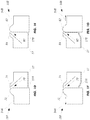
- FIG. 1A illustrates an embodiment of the air stabilization system 10 that includes a stainless steel body that is segmented into a central region 12, lateral region 14A and lateral region 14B.
- Central region 12 has an operative surface 32 that is situated between Coanda nozzles 16A and 16B.
- Each nozzle is formed within a dome-shaped structure protruding from the base of the body so that the nozzles are elevated relative to operative surface 32.
- the dome structures preferably exhibit slope curvatures that extend along the length of the nozzles.
- the air stabilization system 10 is employed with a laser-triangulation displacement measuring device (not shown) that is positioned underneath.
- the laser beam incident on moving web 22 and the reflected light both pass through optical channel or orifice 20 that is formed in central region 12.
- the body further includes a lower portion 6 which supports central region 12 and baffle 17. Lower aperture 8 permits optical access between the caliper device and optical path channel 20.
- Plate member 17 has cantilever structures 17A and 17B which function as internal
- the air stabilization system 10 is positioned underneath a web of material 22 which is moving from left to right relative to the system; this direction being referred to as the downstream machine direction (MD) and the opposite direction being the upstream machine direction.
- the cross direction (CD) is transverse to the MD.
- Upper lateral surfaces 34A and 34B are preferably coplanar with operative surface 32.
- the contour of web 22 as it travels over operative surface 32 can be controlled with the air stabilization system.
- the profile of web 22 is substantially planar.
- the vertical height between web 22 and operative surface 32 can be regulated by controlling the speed of the gases exhausting through Coanda nozzles 16A and 16B. The higher the speed of the gases, the greater the suction force generated by the nozzles that is applied to the web 22.
- the body of air stabilization system 10 further defines a chamber 18A that serves as an opening for Coanda nozzle 16A and a chamber 18B that serves as an opening for Coanda nozzle 16B.
- Baffle 17A separates chamber 18A from plenum chamber 40A which in turn is connected to a source of gas 24A via conduit 30A.
- the gas flow rate into plenum 40A can be regulated by conventional means including pressure controller 28A and flow regulator valve 26A.
- the length of chamber 40A, as measured along the cross direction, preferably matches that of Coanda nozzle 16A.
- Plenum 40A essentially serves as a reservoir in which high pressure gas equilibrates before being evenly distributed along the length of Coanda nozzle 16A via chamber 18A.
- baffle 17A serves to equalize the gas pressure in plenum 40A across the nozzle.
- Conduit 30A can include a single channel which connects the source of gas 24A to plenum 40A; alternatively a plurality of holes drilled into the lower surface of the body can be employed. The plurality of holes should be spaced apart along the cross direction of the body in order to distribute gas evenly into plenum 40A.
- chamber 18B through baffle 17B, is in gaseous communication with plenum chamber 40B which is connected to a source of gas 24B via conduit 30B.
- Baffle 17B serves to equalize the gas pressure in plenum 40B as well.
- Gas flowing into plenum 40B is regulated by pressure controller 28B and flow regulator valve 26B.
- the configurations of chamber 40B and conduit 30B are preferably the same as those of chamber 40A and conduit 30B, respectively. In practice, the pressure is regulated so that the measured flow rates are the same.
- any suitable gas can be employed in gas sources 24A and 24B including for example, air, helium, argon, carbon dioxide.
- the amount of gas employed is that which is sufficient to discharge the gas through the Coanda nozzles at a velocity of about 20 m/s to about 400 m/s.
- the air stabilization system can be employed to support a variety of flexible web products including paper, plastic, and the like. For paper that is continuously manufactured in large scale commercial papermaking machines, the web can travels at speeds of 200 m/min to 1800 m/min or higher. In operation, the air stabilization system preferably maintains paper web 22 at a distance ranging from about 100 ⁇ m to about 1000 ⁇ m above Coanda nozzles 16A and 16B.
- Coanda nozzle 16A has a nozzle opening 70 that is formed on a protruding structure having an upstream upper surface 72 and a downstream upper surface 74.
- Upstream surface 72 is configured as an accurately curved inner surface at nozzle opening 70 whereas downstream surface 74 presents a generally angled planar inner surface at nozzle opening 70.
- Gas emerging from nozzle opening 70 by virtue of the Coanda effect tends to follow a path along the curve of surface portion 72 and to travel upstream from right to left along upper lateral surface 34A. In the process, the surrounding gas is entrained in the air-flow emerging from nozzle opening 70.
- Coanda nozzle 16B with nozzle opening 60 is formed on a protruding structure having a downstream upper surface 62 and an upstream upper surface 64.
- Downstream surface 62 is configured as an accurately curved inner surface at nozzle opening 60 while upstream surface 64 presents a generally angled planar inner surface at nozzle opening 60.
- Gas emerging from nozzle opening 60 follows the curve of surface portion 62 and travels downstream from left to right and along upper lateral surface 34B. Surrounding gas is entrained in the air-flow emerging from nozzle opening 60 to create a suction force.
- FIG ID depicts baffle 17A laterally extending toward the upstream machine direction side of nozzle 16A.
- the distal end of baffle 17A is almost flush with the vertical inner wall.
- baffle 17B extends laterally toward the downstream machine direction side of nozzle 16B.
- pressurized gas from plenum chamber 40A causes the flexible baffle 17A to bend at the edge as the gas is channeled upward along the wall and onto the curved face of Coanda nozzle 16A.
- Figure 1G illustrates the same effect with respect to baffle 17B as pressurize gas from plenum chamber 40B causes the flexible baffle 17B to bend at the edge as the gas is channeled upward along the wall and onto the curved face of Coanda nozzle 16B.
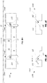
- Figure 2A shows a side view of sheet 22 as it passes over Coanda nozzles 16A and 16B, with each nozzle exhausting a jet of gas in opposite directions.
- the nozzles are set apart sufficiently to define a planar surface 32 between them.
- the sheet motion opposes the force imparted by upstream Coanda nozzle 16A, located at the web entry end, while the sheet motion is parallel to the force imparted by downstream Coanda nozzle 16B, located at the web exit end.
- the simultaneous opposing forces apply a tension on the moving sheet that creates the desired sheet profile between the nozzles as the sheet passes over the operative surface.
- the higher the air velocities from the dual nozzles the greater the clamping force generated.
- the air stabilization system by increasing or decreasing the clamping force from the dual nozzles, the distance between moving web 22 and surface 32 can be correspondingly decreased or increased.
- downstream Coanda nozzle 16B is typically the same as that of upstream Coanda nozzle 16A, their heights can be different. By maintaining a height differential, the sheet profile between the nozzles can be modified. Preferably, the height of each Coanda nozzle ranges from 0.5 to 2.5 mm.
- Figure 2B shows the corresponding velocity profiles of the jets of gas exiting the Coanda nozzles.
- the sheet is moving at a slow speed relative to the speed of the gases exiting the nozzles.
- curve 1 depicts the gas velocity (V) profile along a vertical path or height (H) between Coanda nozzle 16A toward the sheet which is moving in the machine direction.
- the gas velocity decreases gradually and reverses direction at a position near the sheet.
- the gas velocity matches that of the web at the web's surface.
- curve 11 shows a gradual decrease in velocity from the nozzle to the moving web.
- the aerodynamics should be symmetric as the sheet is being essentially supported by the air clamping characteristics of the two nozzles.
- the air stabilizing system can be constructed from five basic units that include a central body member 80, upper body member 46, plate member 17 and side supports 42, 44. They are attached together by conventional means including dowels and screws.
- the generally rectangular-shaped upper body member 46 has outer perimeters, at opposite ends, that define downstream upper surface 74 and upstream surface 64.
- a central region 12 has a measurement orifice 48 that serves as an optical path channel for a laser triangulation caliper device.
- Central body member 80 includes a middle portion 6 and lateral portions 14A and 14B and defines an opening 58 for access to the mounted device within orifice 48.
- the inward facing edge of lateral portion 14A defines upstream upper surface 72 and the inward facing edge of lateral portion 14B defines downstream upper surface 62.
- Plate 17 is preferably constructed of metal such as stainless steel, brass or aluminum that typically ranges from 75 to 125 microns thick with corresponding opening 57.
- the size of the metal sheet is dimensioned to preferably fill the entire space between the gas inlet and exit nozzle on each side of the air clamp (while leaving enough room so that the edges do not catch on the vertical faces below 62 and 72.).
- the air stabilizing system is formed by securing upper body member 46 onto central body member 80, with plate 17 situated between them, so that the upper lateral surfaces 34A and 34B are coplanar with the surface of upper body member 46.
- Side supports 42 and 44 seal the internal plenums and chambers.
- the air stabilization system can be incorporated into on-line dual head scanning sensor systems for papermaking machines which are disclosed in U.S.
- the width of the paper in the papermaking machines generally ranges from 5 to 12 meters and typically is about 9 meters.
- the dual heads which are designed for synchronized movement, consist of an upper head positioned above the sheet and a lower head positioned below the sheet.
- the air stabilization system which is preferably mounted on the lower head, clamps the moving paper to cause it to exhibit an essentially flat sheet profile for measurement as the upper and lower heads travel back and forth in the cross direction over the width of the paper.
- the air clamp can be located in the lower or upper head of a scanning sensor.
- Figure 4 shows an air stabilization system that is incorporated into a recessed compartment within substrate 52 that is part of head 50 of a scanning sensor.
- Measurement orifice 48 is situated between Coanda nozzles 16A and 16B.
- Substrate 52 is positioned so that a web product travels over the air stabilization system in machine direction 54 which is transverse to the lengths of the elongated Coanda nozzles.
- substrate 52 scans back and forth along the cross direction to generate measurements of the paper along the cross direction.
- the distance between nozzles 16A and 16B is about 75 mm and the length of each nozzle along the cross direction is about 50 mm.
- Non-contacting caliper sensors such as those disclosed in U.S. Patent 6,281,679 to King et al ., which is incorporated herein by reference, include upper and lower heads equipped with laser triangulation devices.
- the caliper of a moving sheet that travels between the two heads is determined by identifying the positions of the upper and lower surfaces of the sheet with the laser triangulation devices and subtracting the results from a measure of the separation between the upper and lower heads.
- Figure 5 illustrates a representative non-contacting caliper sensor system that includes first and second scanner heads 13 and 15 respectively, which contain various sensor devices for measuring qualities, characteristics, or features of a moving web of material identified as 3. Heads 13 and 15 lie on opposite sides of web or sheet 3, and, if the measurement is to be performed in a scanning manner across the web in the cross direction, the heads are aligned to travel directly across from each other as they traverse the moving web which is moving in the machine direction.
- a first source/detector 4 is located in first head 13.
- a second source/detector 5 is located in second head 15.
- Source/detectors 4 and 5 comprise closely-spaced first and second sources 4a and 5a, respectively, and first and second detectors 4b and 5b, respectively, arranged so that measurement energy from first source 4a and interacting with a first surface of web 3 will return, at least in part to first detector 4b, and measurement energy from second source 5a and interacting with the opposite, or second surface, of web 3 will return, at least in part to second detector 5b.
- the source and detector preferably comprise a laser triangulation source and detector, collectively being referred to as an interrogation laser.
- the source/detector arrangement is referred to generally as a distance determining means. From the measured path length from the source to the detector, values for the distance between each distance determining means and a measurement or interrogation spot on one of the web surfaces may be determined.
- the heads 13 and 15 are typically fixed in the position so that the interrogations spots do not move in the machine direction even as the heads are scanned in the cross direction.
- first distance determining means 4 For first distance determining means 4, the detected distance value between the distance determining means and a first measurement spot on the web surface (referred to as l 1 ) and for second distance determining means 5, the detected distance value between the distance determining means and a second measurement spot on the opposite web surface (referred to as l 2 ).
- separation s can vary.
- a dynamic measurement of the spacing between the scanning heads is provided by a z-sensor means, which measures a distance z, between a z-sensor source/detector 6, located in the first head 13, and a z-sensor reference 7, located in the second head 15.
- the air stabilization system of the present invention is employed with either the lower head, upper head, or both heads to keep the sheet flat so that small head misalignments do not translate into erroneous caliper readings, i.e., caliper error due to head misalignment and sheet angle.
- FIG 6A illustrates an example air stabilization system 110 with a smooth, flush operative surface, supporting moving web 22.
- the stabilizer includes a body that is segmented into a central region 12, lateral region 14A and lateral region 14B.
- Central region 12 has an operative surface 132 that is situated between Coanda nozzles 116A and 116B, which are in gaseous communication with chambers 18A and 18B, respectively.
- Coanda nozzles 116A and 116B exhaust jets of gas in opposite directions.
- the internal gas flows in the nozzles are restricted by baffles 17A and 17B of plate 17, respectively.
- Independently regulated sources of pressurized gas which are described above for the air stabilization system 10 of Figure 1A , can be employed and are connected to chamber 18A and 18B.
- Central region 12 defines an optical channel 20 whose upper surface is flush with operative surface 132 and is part of the operative surface 132.
- the body further includes a lower portion 6 which supports central region 12.
- Aperture 8 permits access to optical channel 20.
- Upper lateral surfaces 134A and 134B are preferably coplanar with operative surface 132 to define a smooth flush surface over the body.
- Coanda nozzle 116A has a Coanda slot 170 between upper surface 134A and operative surface 132.
- Coanda slot 170 has a curved convex surface 172 on its downstream side.
- this surface has a radius of curvature (R) ranging from about 1.0 mm to about 10 mm.
- Gas flow from Coanda slot 170 follows the downstream trajectory of curved surface 172, so as to flow in the upstream MD relative to the moving web.
- slot 170 has a width (w) of about 76 ⁇ m (3 mils) to about 127 ⁇ m (5 mils).
- the air clamp's suction force draws the web closer to the stabilizer as the web approaches the stabilizer. However, the web should not be permitted to get too close to the nozzles as this would actually cut off gas flow from the nozzles. This would cause the local pressure to rise and the increase force would push to web away from the stabilizer.
- Coanda nozzle 116B has a Coanda slot 160 between upper surface 134B and operative surface 132.
- Coanda slot 160 has a curved convex surface 162 on its downstream side. Gas flow from the Coanda slot 160 follows the downstream trajectory of curved surface 162 so as to flow in the downstream MD.
- the dimensions of Coanda nozzle 116B can be the same as those of Coanda nozzle 116A.
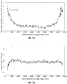
- a stainless steel air clamp stabilizer having the configuration shown in Figures 6A, 6B and 6C was incorporated into a laser triangulation scanning sensor.
- Each of the two Coanda nozzles had a slot having a width (w) of 0.1 mm and a curvature radius (R) of 1.5 mm.
- the nozzles were approximately 43 mm apart as measured from the center of each nozzle slot.
- the air clamp was employed to support a moving web of paper that was traveling at about 1500 m/min and had a basis weight of 45 grams per square meter (gsm).
- the term "basis weight” refers to the mass or weight per unit area of the paper.
- the distance between the upper surface of the paper and the center of the operative surface of the air stabilizer was measured as the sensor was scanned across the 8.5 m sheet with a laser triangulation sensor as the paper sheet moved horizontally over the surface of the air clamp stabilizer.
- Figure 7A depicts the height of the sheet around the mean distance vs. the scanner displacement or position in the cross direction of the moving sheet. The curve shows that the sheet contour is substantially flat; the 2-sigma variation in the sheet height is 2.7 microns.
- Figure 7B depicts the corresponding laser caliper profile derived from 10 cross direction scans from one side of the paper to the other.
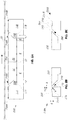
- Figure 8A illustrates an embodiment of the air stabilization system 210 that incorporates opposite-facing nozzles that are configured with backsteps that increase the suction force which is applied to moving web 22.
- the stabilizer includes a body that is segmented into a central region 12, lateral region 14A and lateral region 14B.
- Central region 12 has an operative surface 232 that is situated between Coanda nozzles 216A and 216B, which are in gaseous communication with chambers 18A and 18B, respectively.
- Coanda nozzles 216A and 216B exhaust jets of gas in opposite directions toward surface 234A and 234B, respectively, which are downstream of the backstep features of nozzles.
- baffles 17A and 17B of plate 17 again equalizes the gas pressure in the plenum chambers.
- Independently regulated sources of pressurized gas which are described above for the air stabilization system 10 of Figure 1A , can be employed and are connected to chamber 18A and 18B.
- Central region 12 includes an optical channel 20.
- the body further includes a lower portion 6 which supports central region 12.
- Aperture 8 permits access to optical channel 20.
- Coanda nozzle 216A has a Coanda slot 270 between upper surface 274 and operative surface 232 which are preferably coplanar.
- Coanda slot 270 has a curved convex surface 272 on its downstream side.
- this surface has a radius of curvature (R) ranging from about 1.0 mm to about 10 mm, and in one embodiment it is about 1.6 mm.
- Airflow from the Coanda slot 270 follows the trajectory of the curved surface 272.
- the term "backstep" is meant to encompass a depression on the stabilizer surface located a distance downstream from Coanda slot 270 preferably sufficient to create a vortex. The combination of the Coanda slot and backstep generates an amplified suction force and an extensive air bearing.
- backstep 220 allows a Coanda jet to expand and create an additional suction force. It should be noted that jet expansion is necessary to create the suction force but vortex formation is not a prerequisite. Indeed, vortex formation does not always occur downstream from the backstep and is not necessary for operation of the air clamp stabilizer.
- the stabilizer's suction force initially draws the web closer to the stabilizer as the web approaches the stabilizer. Subsequently, the air bearing supports and reshapes the web so that the web exhibits a relatively flat profile as it passes over the backstep. While backstep 220 is most preferably configured as a 90 degrees vertical wall, the backstep can exhibit a more gradual contour so that the upper and lower surfaces can be joined by a smooth, concavely curved surface.
- Coanda slot 270 has a width (b) of about 76 ⁇ m (3 mils) to about 127 ⁇ m (5 mils).
- the distance (d) from the upper surface 274 to lower surface 234A, which are preferably parallel to each other, is preferably between about 100 to 1000 ⁇ m.
- the backstep location (L) is about 1 mm to about 6 mm and preferably about 2 mm to 3 from Coanda slot 270.
- Coanda nozzle 216B has a Coanda slot 260 between upper surface 264 and operative surface 232.
- Coanda slot 260 has a curved surface 262 on its downstream side.
- the dimensions of structures forming Coanda nozzle 216B, including backstep 230 and lower surface 234B, can be the same as those for Coanda nozzle 216A.
- Figure 9 illustrates an embodiment of air stabilization system 310 wherein the operative surface 332 is located on the lower surface of channel 336 that is formed in the body of the stabilizer.
- operative surface 332 is located farther away from moving web 22 to reduce the likelihood that web 22 comes into contact with operative surface 332.
- the stabilizer includes a body that is segmented into a central region 12, lateral region 14A, with upper surface 334A, and lateral region 14B, with upper surface 334B.
- Plate 17 forms baffles 17A and 17B.
- Central region 12 has an optical operative surface 332 that is situated between opposite facing Coanda nozzles 316A and 316B, which are in gaseous communication with chambers 18A and 18B, respectively.
- Central region 12 defines an optical channel 20.
- the depth of channel 334 within central region 12 can range from 1400 ⁇ m to 2000 ⁇ m or more.
- the remaining structures of the stabilizer can be same as those illustrated in Figure 6A ; however, it is understood that a channel can be incorporated into any air stabilization system described above to provide additional clearance between the moving web and operative surface.
- Figure 10 illustrates the air stabilization system of Figure 9 with a transparent substrate 420, such as glass, inserted within channel 334 in order to cover optical channel 20.
- Substrate 420 prevents debris from accumulating within optical channel 20 which can adversely affect sensor measurements and distort the web profile.
- Upper surface 432 of substrate 420 which presents a smooth surface, eliminates these potential problems.
- Transparent substrates can also be employed with any of the air stabilization systems described above.
- Upper surface 432 is preferably coplanar with upper surfaces 334A and 334B so that the surfaces of the stabilizer are flush.
- Plate 17 forms baffles 17A and 17B.
- Figure 11 illustrates an embodiment of air stabilization system 510 that includes a body that is segmented into a central region 12, lateral region 14A, with upper surface 334A, and lateral region 14B, with upper surface 334B.
- Upper surfaces 334A and 334B are preferably parallel and coplanar.
- Central region 12 is set back so that central operative surface 532 is farther away from moving web 22, than are upper surfaces 334A and 334B, to reduce the likelihood that web 22 comes into contact with operative surface 532.
- Plate 17 forms baffles 17A and 17B.
- Central operative surface 532 is preferably about 0.64 mm (0.025 in.) to 0.28 mm (0.011 in.) lowered that the lateral operative surfaces formed by upper surfaces 334A and 334B.
- Opposite facing Coanda nozzles 516A and 516B are in gaseous communication with chambers 18A and 18B, respectively.
- the remaining structures of the stabilizer can be same as those illustrated in Figure 6A .
- the recessed centerpiece is often combined with the backstep design shown in Figure 8 .
Landscapes
- Advancing Webs (AREA)
Applications Claiming Priority (3)
| Application Number | Priority Date | Filing Date | Title |
|---|---|---|---|
| US10067708P | 2008-09-26 | 2008-09-26 | |
| US12/547,323 US8083896B2 (en) | 2008-09-26 | 2009-08-25 | Pressure equalizing baffle and coanda air clamp |
| PCT/US2009/057121 WO2010036546A1 (en) | 2008-09-26 | 2009-09-16 | Pressure equalizing baffle and coanda air clamp |
Publications (3)
| Publication Number | Publication Date |
|---|---|
| EP2326583A1 EP2326583A1 (en) | 2011-06-01 |
| EP2326583A4 EP2326583A4 (en) | 2012-05-30 |
| EP2326583B1 true EP2326583B1 (en) | 2019-12-04 |
Family
ID=42056127
Family Applications (1)
| Application Number | Title | Priority Date | Filing Date |
|---|---|---|---|
| EP09816712.5A Active EP2326583B1 (en) | 2008-09-26 | 2009-09-16 | Pressure equalizing baffle and coanda air clamp |
Country Status (5)
| Country | Link |
|---|---|
| US (1) | US8083896B2 (https=) |
| EP (1) | EP2326583B1 (https=) |
| JP (1) | JP5466706B2 (https=) |
| CA (1) | CA2738720C (https=) |
| WO (1) | WO2010036546A1 (https=) |
Families Citing this family (14)
| Publication number | Priority date | Publication date | Assignee | Title |
|---|---|---|---|---|
| EP2250109B1 (en) | 2008-03-11 | 2015-01-14 | Coreflow Ltd. | Method and system for locally controlling support of a flat object |
| US8083895B2 (en) * | 2008-04-18 | 2011-12-27 | Honeywell Asca Inc. | Sheet stabilization with dual opposing cross direction air clamps |
| US8088255B2 (en) * | 2008-04-18 | 2012-01-03 | Honeywell Asca Inc | Sheet stabilizer with dual inline machine direction air clamps and backsteps |
| DE102008002087A1 (de) * | 2008-05-29 | 2009-12-03 | Voith Patent Gmbh | Anlage zur Herstellung einer Faserstoffbahn |
| US8083896B2 (en) * | 2008-09-26 | 2011-12-27 | Honeywell Asca Inc. | Pressure equalizing baffle and coanda air clamp |
| SE535329C2 (sv) * | 2010-11-29 | 2012-06-26 | Andritz Tech & Asset Man Gmbh | Metod för att torka en massabana och en massatork innefattande en inspektionsanordning för analysering av massabanans position eller förekomst av massarester |
| US8760669B2 (en) | 2011-09-30 | 2014-06-24 | Honeywell Asca Inc. | Method of measuring the thickness of a moving web |
| US9007589B2 (en) | 2013-09-16 | 2015-04-14 | Honeywell Asca Inc. | Co-located porosity and caliper measurement for membranes and other web products |
| US10259104B2 (en) | 2013-10-28 | 2019-04-16 | Nikon Corporation | Precision clamp |
| SE538854C2 (sv) * | 2014-01-09 | 2017-01-03 | Valmet Oy | Rullstol för mottagande och upprullning av en pappersbana, som kommer från en torkcylinder i en pappersmaskin, till en rulle, samt en pappersmaskin som använder en rullstol |
| FI126243B (fi) * | 2015-01-14 | 2016-08-31 | Takso-Ohjelmistot Oy | Laite ja menetelmä kuiturainan manipuloimiseksi |
| US9889995B1 (en) * | 2017-03-15 | 2018-02-13 | Core Flow Ltd. | Noncontact support platform with blockage detection |
| FI20185410A1 (en) * | 2018-05-03 | 2019-11-04 | Valmet Automation Oy | MEASUREMENT OF THE MOVING RAIN FACTOR |
| CN114541166B (zh) * | 2022-01-29 | 2024-03-08 | 江苏理文造纸有限公司 | 一种可形成双级真空区的稳纸箱及造纸机 |
Family Cites Families (35)
| Publication number | Priority date | Publication date | Assignee | Title |
|---|---|---|---|---|
| DE1951002C3 (de) * | 1969-10-09 | 1974-02-07 | Vits-Maschinenbau Gmbh, 4018 Langenfeld | Einrichtung zur berührungslosen Stabilisierung einer in ihrer Längsrichtung gespannten und bewegten Warenbahn |
| US3873013A (en) * | 1973-10-04 | 1975-03-25 | Tec Systems | High velocity web floating air bar having center exhaust means |
| NO141469L (https=) * | 1975-12-09 | |||
| DE2556442C2 (de) * | 1975-12-15 | 1984-09-06 | Gerhardt, Hans-Joachim, Prof. M.Sc. Dipl.-Ing., 5100 Aachen | Vorrichtung zur schwebend Führung von Warenbahnen |
| US4201323A (en) * | 1978-10-12 | 1980-05-06 | W. R. Grace & Co. | High velocity web floating air bar having a recessed Coanda plate |
| FI76435C (fi) * | 1982-05-17 | 1988-10-10 | Measurex Corp | Maetanordning foer maetning av ett arkmaterial. |
| US4472888A (en) * | 1982-06-04 | 1984-09-25 | Cary Metal Products, Inc. | Coanda effect nozzle for handling continuous webs |
| GB2146303B (en) * | 1983-08-20 | 1987-01-14 | Spooner Ind Ltd | Device for supporting web on a bed of air |
| US4879471A (en) * | 1987-03-25 | 1989-11-07 | Measurex Corporation | Rapid-scanning infrared sensor |
| DE3715533C2 (de) * | 1987-05-09 | 1997-07-17 | Krieger Gmbh & Co Kg | Vorrichtung zum Schwebendführen von Materialbahnen |
| US5014447A (en) * | 1988-02-10 | 1991-05-14 | Thermo Electron Web Systems, Inc. | Positive pressure web floater dryer with parallel flow |
| US4901449A (en) * | 1988-06-07 | 1990-02-20 | W. R. Grace & Co.-Conn. | Tri-flotation air bar |
| US5092059A (en) * | 1988-06-07 | 1992-03-03 | W. R. Grace & Co.-Conn. | Infrared air float bar |
| US5094535A (en) | 1989-10-06 | 1992-03-10 | Measurex Corporation | Scanning sensor system including an FT-IR interferometer |
| US5166748A (en) * | 1989-10-06 | 1992-11-24 | Measurex Corporation | Scanning interferometer sensor system |
| US5156312A (en) * | 1989-12-29 | 1992-10-20 | Somerset Technologies, Inc. | Flotation nozzle for web handling equipment |
| US5395029A (en) * | 1989-12-29 | 1995-03-07 | Somerset Technologies, Inc. | Flotation nozzle for web handling equipment |
| US5125170A (en) * | 1990-04-11 | 1992-06-30 | Worldwide Converting Machinery | Flotation dryer nozzle |
| US5094545A (en) * | 1990-09-28 | 1992-03-10 | Pyma Corporation | Urine temperature measuring device |
| FI96125C (fi) * | 1991-09-05 | 1996-05-10 | Valmet Paper Machinery Inc | Rainojen käsittelyyn tarkoitettu alipainesuutinjärjestely ja menetelmä rainojen käsittelyyn tarkoitetussa alipainesuutinjärjestelyssä |
| JPH0631407A (ja) | 1992-07-21 | 1994-02-08 | Kawasaki Steel Corp | 薄帯の搬送装置 |
| US5471766A (en) * | 1993-03-18 | 1995-12-05 | Valmet Paper Machinery, Inc. | Method in contact-free air-drying of a material web as well as a nozzle-blow-box and a pulp dryer that make use of the method |
| DE19821542C2 (de) * | 1998-05-14 | 2000-05-11 | Langbein & Engelbracht Gmbh | Blaskasten |
| US5951006A (en) | 1998-05-22 | 1999-09-14 | Xerox Corporation | Modular air jet array with coanda exhausting for module decoupling |
| US6281679B1 (en) * | 1998-12-21 | 2001-08-28 | Honeywell - Measurex | Web thickness measurement system |
| FI114337B (fi) * | 2001-07-03 | 2004-09-30 | Metso Automation Oy | Menetelmä ja mittalaite liikkuvan rainan ainakin yhden ominaisuuden mittaamiseksi |
| US6936137B2 (en) * | 2001-10-24 | 2005-08-30 | Honeywell International Inc. | Air clamp stabilizer for continuous web materials |
| KR200325228Y1 (ko) * | 2002-07-29 | 2003-09-02 | 문상협 | 제트 수영화 |
| US6967726B2 (en) * | 2003-10-03 | 2005-11-22 | Honeywell International Inc. | Means for in-place automated calibration of optically-based thickness sensor |
| US7530179B2 (en) * | 2004-04-13 | 2009-05-12 | Megtec Systems, Inc. | Step air foil |
| FI116229B (fi) | 2004-04-29 | 2005-10-14 | Metso Paper Inc | Sivuohjauksella varustettu alipainehihnakuljetin rainanmuodostuskonetta varten |
| US8282781B2 (en) * | 2006-12-11 | 2012-10-09 | Honeywell International Inc. | Apparatus and method for stabilization of a moving sheet relative to a sensor |
| US8088255B2 (en) * | 2008-04-18 | 2012-01-03 | Honeywell Asca Inc | Sheet stabilizer with dual inline machine direction air clamps and backsteps |
| US7892399B2 (en) * | 2008-05-29 | 2011-02-22 | Honeywell Asca Inc. | Local tension generating air stabilization system for web products |
| US8083896B2 (en) * | 2008-09-26 | 2011-12-27 | Honeywell Asca Inc. | Pressure equalizing baffle and coanda air clamp |
-
2009
- 2009-08-25 US US12/547,323 patent/US8083896B2/en active Active
- 2009-09-16 CA CA2738720A patent/CA2738720C/en active Active
- 2009-09-16 JP JP2011529116A patent/JP5466706B2/ja active Active
- 2009-09-16 WO PCT/US2009/057121 patent/WO2010036546A1/en not_active Ceased
- 2009-09-16 EP EP09816712.5A patent/EP2326583B1/en active Active
Non-Patent Citations (1)
| Title |
|---|
| None * |
Also Published As
| Publication number | Publication date |
|---|---|
| JP5466706B2 (ja) | 2014-04-09 |
| CA2738720C (en) | 2016-10-18 |
| US20100078140A1 (en) | 2010-04-01 |
| EP2326583A4 (en) | 2012-05-30 |
| EP2326583A1 (en) | 2011-06-01 |
| CA2738720A1 (en) | 2010-04-01 |
| JP2012503583A (ja) | 2012-02-09 |
| US8083896B2 (en) | 2011-12-27 |
| WO2010036546A1 (en) | 2010-04-01 |
Similar Documents
| Publication | Publication Date | Title |
|---|---|---|
| EP2326583B1 (en) | Pressure equalizing baffle and coanda air clamp | |
| EP2286026B1 (en) | Local tension generating air stabilization system for web products | |
| EP2262710B1 (en) | Sheet stabilization with dual opposing cross direction air clamps | |
| EP2262947B1 (en) | Sheet stabilizer with dual inline machine direction air clamps and backsteps | |
| CA2464704C (en) | Air clamp stabilizer for continuous web materials | |
| US6743338B2 (en) | Method and measuring device for measuring at least one property of moving web | |
| US8760669B2 (en) | Method of measuring the thickness of a moving web | |
| US7528400B2 (en) | Optical translation of triangulation position measurement | |
| EP2302319B1 (en) | Radiation inspection apparatus | |
| CN101379366A (zh) | 三角测量位置测量的光学平移 | |
| US6494081B1 (en) | Method of measuring properties of paper, and arrangement in a paper measuring apparatus |
Legal Events
| Date | Code | Title | Description |
|---|---|---|---|
| PUAI | Public reference made under article 153(3) epc to a published international application that has entered the european phase |
Free format text: ORIGINAL CODE: 0009012 |
|
| 17P | Request for examination filed |
Effective date: 20110223 |
|
| AK | Designated contracting states |
Kind code of ref document: A1 Designated state(s): AT BE BG CH CY CZ DE DK EE ES FI FR GB GR HR HU IE IS IT LI LT LU LV MC MK MT NL NO PL PT RO SE SI SK SM TR |
|
| AX | Request for extension of the european patent |
Extension state: AL BA RS |
|
| DAX | Request for extension of the european patent (deleted) | ||
| A4 | Supplementary search report drawn up and despatched |
Effective date: 20120502 |
|
| RIC1 | Information provided on ipc code assigned before grant |
Ipc: D21F 1/42 20060101ALI20120424BHEP Ipc: B65H 23/24 20060101ALI20120424BHEP Ipc: D21F 5/18 20060101ALI20120424BHEP Ipc: D21F 1/36 20060101ALI20120424BHEP Ipc: B65H 20/14 20060101AFI20120424BHEP |
|
| 17Q | First examination report despatched |
Effective date: 20120529 |
|
| STAA | Information on the status of an ep patent application or granted ep patent |
Free format text: STATUS: EXAMINATION IS IN PROGRESS |
|
| GRAP | Despatch of communication of intention to grant a patent |
Free format text: ORIGINAL CODE: EPIDOSNIGR1 |
|
| STAA | Information on the status of an ep patent application or granted ep patent |
Free format text: STATUS: GRANT OF PATENT IS INTENDED |
|
| INTG | Intention to grant announced |
Effective date: 20190612 |
|
| GRAS | Grant fee paid |
Free format text: ORIGINAL CODE: EPIDOSNIGR3 |
|
| GRAJ | Information related to disapproval of communication of intention to grant by the applicant or resumption of examination proceedings by the epo deleted |
Free format text: ORIGINAL CODE: EPIDOSDIGR1 |
|
| GRAL | Information related to payment of fee for publishing/printing deleted |
Free format text: ORIGINAL CODE: EPIDOSDIGR3 |
|
| STAA | Information on the status of an ep patent application or granted ep patent |
Free format text: STATUS: EXAMINATION IS IN PROGRESS |
|
| GRAP | Despatch of communication of intention to grant a patent |
Free format text: ORIGINAL CODE: EPIDOSNIGR1 |
|
| STAA | Information on the status of an ep patent application or granted ep patent |
Free format text: STATUS: GRANT OF PATENT IS INTENDED |
|
| INTC | Intention to grant announced (deleted) | ||
| GRAA | (expected) grant |
Free format text: ORIGINAL CODE: 0009210 |
|
| STAA | Information on the status of an ep patent application or granted ep patent |
Free format text: STATUS: THE PATENT HAS BEEN GRANTED |
|
| INTG | Intention to grant announced |
Effective date: 20191023 |
|
| AK | Designated contracting states |
Kind code of ref document: B1 Designated state(s): AT BE BG CH CY CZ DE DK EE ES FI FR GB GR HR HU IE IS IT LI LT LU LV MC MK MT NL NO PL PT RO SE SI SK SM TR |
|
| REG | Reference to a national code |
Ref country code: GB Ref legal event code: FG4D |
|
| REG | Reference to a national code |
Ref country code: CH Ref legal event code: EP |
|
| REG | Reference to a national code |
Ref country code: AT Ref legal event code: REF Ref document number: 1209141 Country of ref document: AT Kind code of ref document: T Effective date: 20191215 |
|
| REG | Reference to a national code |
Ref country code: DE Ref legal event code: R096 Ref document number: 602009060641 Country of ref document: DE |
|
| REG | Reference to a national code |
Ref country code: IE Ref legal event code: FG4D |
|
| REG | Reference to a national code |
Ref country code: FI Ref legal event code: FGE |
|
| REG | Reference to a national code |
Ref country code: NL Ref legal event code: MP Effective date: 20191204 |
|
| REG | Reference to a national code |
Ref country code: LT Ref legal event code: MG4D |
|
| PG25 | Lapsed in a contracting state [announced via postgrant information from national office to epo] |
Ref country code: GR Free format text: LAPSE BECAUSE OF FAILURE TO SUBMIT A TRANSLATION OF THE DESCRIPTION OR TO PAY THE FEE WITHIN THE PRESCRIBED TIME-LIMIT Effective date: 20200305 Ref country code: NO Free format text: LAPSE BECAUSE OF FAILURE TO SUBMIT A TRANSLATION OF THE DESCRIPTION OR TO PAY THE FEE WITHIN THE PRESCRIBED TIME-LIMIT Effective date: 20200304 Ref country code: ES Free format text: LAPSE BECAUSE OF FAILURE TO SUBMIT A TRANSLATION OF THE DESCRIPTION OR TO PAY THE FEE WITHIN THE PRESCRIBED TIME-LIMIT Effective date: 20191204 Ref country code: SE Free format text: LAPSE BECAUSE OF FAILURE TO SUBMIT A TRANSLATION OF THE DESCRIPTION OR TO PAY THE FEE WITHIN THE PRESCRIBED TIME-LIMIT Effective date: 20191204 Ref country code: LV Free format text: LAPSE BECAUSE OF FAILURE TO SUBMIT A TRANSLATION OF THE DESCRIPTION OR TO PAY THE FEE WITHIN THE PRESCRIBED TIME-LIMIT Effective date: 20191204 Ref country code: BG Free format text: LAPSE BECAUSE OF FAILURE TO SUBMIT A TRANSLATION OF THE DESCRIPTION OR TO PAY THE FEE WITHIN THE PRESCRIBED TIME-LIMIT Effective date: 20200304 Ref country code: LT Free format text: LAPSE BECAUSE OF FAILURE TO SUBMIT A TRANSLATION OF THE DESCRIPTION OR TO PAY THE FEE WITHIN THE PRESCRIBED TIME-LIMIT Effective date: 20191204 |
|
| PG25 | Lapsed in a contracting state [announced via postgrant information from national office to epo] |
Ref country code: HR Free format text: LAPSE BECAUSE OF FAILURE TO SUBMIT A TRANSLATION OF THE DESCRIPTION OR TO PAY THE FEE WITHIN THE PRESCRIBED TIME-LIMIT Effective date: 20191204 |
|
| PG25 | Lapsed in a contracting state [announced via postgrant information from national office to epo] |
Ref country code: EE Free format text: LAPSE BECAUSE OF FAILURE TO SUBMIT A TRANSLATION OF THE DESCRIPTION OR TO PAY THE FEE WITHIN THE PRESCRIBED TIME-LIMIT Effective date: 20191204 Ref country code: CZ Free format text: LAPSE BECAUSE OF FAILURE TO SUBMIT A TRANSLATION OF THE DESCRIPTION OR TO PAY THE FEE WITHIN THE PRESCRIBED TIME-LIMIT Effective date: 20191204 Ref country code: NL Free format text: LAPSE BECAUSE OF FAILURE TO SUBMIT A TRANSLATION OF THE DESCRIPTION OR TO PAY THE FEE WITHIN THE PRESCRIBED TIME-LIMIT Effective date: 20191204 Ref country code: RO Free format text: LAPSE BECAUSE OF FAILURE TO SUBMIT A TRANSLATION OF THE DESCRIPTION OR TO PAY THE FEE WITHIN THE PRESCRIBED TIME-LIMIT Effective date: 20191204 Ref country code: PT Free format text: LAPSE BECAUSE OF FAILURE TO SUBMIT A TRANSLATION OF THE DESCRIPTION OR TO PAY THE FEE WITHIN THE PRESCRIBED TIME-LIMIT Effective date: 20200429 |
|
| PG25 | Lapsed in a contracting state [announced via postgrant information from national office to epo] |
Ref country code: SK Free format text: LAPSE BECAUSE OF FAILURE TO SUBMIT A TRANSLATION OF THE DESCRIPTION OR TO PAY THE FEE WITHIN THE PRESCRIBED TIME-LIMIT Effective date: 20191204 Ref country code: SM Free format text: LAPSE BECAUSE OF FAILURE TO SUBMIT A TRANSLATION OF THE DESCRIPTION OR TO PAY THE FEE WITHIN THE PRESCRIBED TIME-LIMIT Effective date: 20191204 Ref country code: IS Free format text: LAPSE BECAUSE OF FAILURE TO SUBMIT A TRANSLATION OF THE DESCRIPTION OR TO PAY THE FEE WITHIN THE PRESCRIBED TIME-LIMIT Effective date: 20200404 |
|
| REG | Reference to a national code |
Ref country code: DE Ref legal event code: R097 Ref document number: 602009060641 Country of ref document: DE |
|
| REG | Reference to a national code |
Ref country code: AT Ref legal event code: MK05 Ref document number: 1209141 Country of ref document: AT Kind code of ref document: T Effective date: 20191204 |
|
| PLBE | No opposition filed within time limit |
Free format text: ORIGINAL CODE: 0009261 |
|
| STAA | Information on the status of an ep patent application or granted ep patent |
Free format text: STATUS: NO OPPOSITION FILED WITHIN TIME LIMIT |
|
| PG25 | Lapsed in a contracting state [announced via postgrant information from national office to epo] |
Ref country code: DK Free format text: LAPSE BECAUSE OF FAILURE TO SUBMIT A TRANSLATION OF THE DESCRIPTION OR TO PAY THE FEE WITHIN THE PRESCRIBED TIME-LIMIT Effective date: 20191204 |
|
| PGFP | Annual fee paid to national office [announced via postgrant information from national office to epo] |
Ref country code: DE Payment date: 20200928 Year of fee payment: 12 |
|
| 26N | No opposition filed |
Effective date: 20200907 |
|
| PG25 | Lapsed in a contracting state [announced via postgrant information from national office to epo] |
Ref country code: PL Free format text: LAPSE BECAUSE OF FAILURE TO SUBMIT A TRANSLATION OF THE DESCRIPTION OR TO PAY THE FEE WITHIN THE PRESCRIBED TIME-LIMIT Effective date: 20191204 Ref country code: SI Free format text: LAPSE BECAUSE OF FAILURE TO SUBMIT A TRANSLATION OF THE DESCRIPTION OR TO PAY THE FEE WITHIN THE PRESCRIBED TIME-LIMIT Effective date: 20191204 Ref country code: AT Free format text: LAPSE BECAUSE OF FAILURE TO SUBMIT A TRANSLATION OF THE DESCRIPTION OR TO PAY THE FEE WITHIN THE PRESCRIBED TIME-LIMIT Effective date: 20191204 |
|
| PG25 | Lapsed in a contracting state [announced via postgrant information from national office to epo] |
Ref country code: IT Free format text: LAPSE BECAUSE OF FAILURE TO SUBMIT A TRANSLATION OF THE DESCRIPTION OR TO PAY THE FEE WITHIN THE PRESCRIBED TIME-LIMIT Effective date: 20191204 |
|
| PG25 | Lapsed in a contracting state [announced via postgrant information from national office to epo] |
Ref country code: MC Free format text: LAPSE BECAUSE OF FAILURE TO SUBMIT A TRANSLATION OF THE DESCRIPTION OR TO PAY THE FEE WITHIN THE PRESCRIBED TIME-LIMIT Effective date: 20191204 |
|
| REG | Reference to a national code |
Ref country code: CH Ref legal event code: PL |
|
| REG | Reference to a national code |
Ref country code: BE Ref legal event code: MM Effective date: 20200930 |
|
| PG25 | Lapsed in a contracting state [announced via postgrant information from national office to epo] |
Ref country code: LU Free format text: LAPSE BECAUSE OF NON-PAYMENT OF DUE FEES Effective date: 20200916 |
|
| PG25 | Lapsed in a contracting state [announced via postgrant information from national office to epo] |
Ref country code: FR Free format text: LAPSE BECAUSE OF NON-PAYMENT OF DUE FEES Effective date: 20200930 |
|
| PG25 | Lapsed in a contracting state [announced via postgrant information from national office to epo] |
Ref country code: BE Free format text: LAPSE BECAUSE OF NON-PAYMENT OF DUE FEES Effective date: 20200930 Ref country code: CH Free format text: LAPSE BECAUSE OF NON-PAYMENT OF DUE FEES Effective date: 20200930 Ref country code: LI Free format text: LAPSE BECAUSE OF NON-PAYMENT OF DUE FEES Effective date: 20200930 Ref country code: IE Free format text: LAPSE BECAUSE OF NON-PAYMENT OF DUE FEES Effective date: 20200916 |
|
| REG | Reference to a national code |
Ref country code: DE Ref legal event code: R119 Ref document number: 602009060641 Country of ref document: DE |
|
| PG25 | Lapsed in a contracting state [announced via postgrant information from national office to epo] |
Ref country code: TR Free format text: LAPSE BECAUSE OF FAILURE TO SUBMIT A TRANSLATION OF THE DESCRIPTION OR TO PAY THE FEE WITHIN THE PRESCRIBED TIME-LIMIT Effective date: 20191204 Ref country code: MT Free format text: LAPSE BECAUSE OF FAILURE TO SUBMIT A TRANSLATION OF THE DESCRIPTION OR TO PAY THE FEE WITHIN THE PRESCRIBED TIME-LIMIT Effective date: 20191204 Ref country code: CY Free format text: LAPSE BECAUSE OF FAILURE TO SUBMIT A TRANSLATION OF THE DESCRIPTION OR TO PAY THE FEE WITHIN THE PRESCRIBED TIME-LIMIT Effective date: 20191204 |
|
| PG25 | Lapsed in a contracting state [announced via postgrant information from national office to epo] |
Ref country code: MK Free format text: LAPSE BECAUSE OF FAILURE TO SUBMIT A TRANSLATION OF THE DESCRIPTION OR TO PAY THE FEE WITHIN THE PRESCRIBED TIME-LIMIT Effective date: 20191204 |
|
| PG25 | Lapsed in a contracting state [announced via postgrant information from national office to epo] |
Ref country code: DE Free format text: LAPSE BECAUSE OF NON-PAYMENT OF DUE FEES Effective date: 20220401 |
|
| PGFP | Annual fee paid to national office [announced via postgrant information from national office to epo] |
Ref country code: FI Payment date: 20250925 Year of fee payment: 17 |
|
| PGFP | Annual fee paid to national office [announced via postgrant information from national office to epo] |
Ref country code: GB Payment date: 20250923 Year of fee payment: 17 |