EP2326552B1 - Method of locating a subsea structure for deployment - Google Patents
Method of locating a subsea structure for deployment Download PDFInfo
- Publication number
- EP2326552B1 EP2326552B1 EP09785569.6A EP09785569A EP2326552B1 EP 2326552 B1 EP2326552 B1 EP 2326552B1 EP 09785569 A EP09785569 A EP 09785569A EP 2326552 B1 EP2326552 B1 EP 2326552B1
- Authority
- EP
- European Patent Office
- Prior art keywords
- buoyancy
- subsea structure
- vessel
- fluid
- deployment
- Prior art date
- Legal status (The legal status is an assumption and is not a legal conclusion. Google has not performed a legal analysis and makes no representation as to the accuracy of the status listed.)
- Not-in-force
Links
- 238000000034 method Methods 0.000 title claims description 44
- 239000012530 fluid Substances 0.000 claims description 71
- 238000007667 floating Methods 0.000 claims description 39
- XLYOFNOQVPJJNP-UHFFFAOYSA-N water Substances O XLYOFNOQVPJJNP-UHFFFAOYSA-N 0.000 claims description 27
- 239000013535 sea water Substances 0.000 claims description 9
- 238000009434 installation Methods 0.000 claims description 7
- OKKJLVBELUTLKV-UHFFFAOYSA-N Methanol Chemical compound OC OKKJLVBELUTLKV-UHFFFAOYSA-N 0.000 claims description 6
- 238000004891 communication Methods 0.000 claims description 5
- 239000013013 elastic material Substances 0.000 claims description 2
- 239000011521 glass Substances 0.000 claims description 2
- 229930195733 hydrocarbon Natural products 0.000 claims description 2
- 150000002430 hydrocarbons Chemical class 0.000 claims description 2
- 239000004005 microsphere Substances 0.000 claims description 2
- 239000004215 Carbon black (E152) Substances 0.000 claims 1
- 230000033001 locomotion Effects 0.000 description 7
- 230000032258 transport Effects 0.000 description 4
- 238000011084 recovery Methods 0.000 description 3
- 238000012546 transfer Methods 0.000 description 3
- 230000002706 hydrostatic effect Effects 0.000 description 2
- 239000003981 vehicle Substances 0.000 description 2
- 241000270295 Serpentes Species 0.000 description 1
- 230000003247 decreasing effect Effects 0.000 description 1
- 230000000694 effects Effects 0.000 description 1
- 239000000499 gel Substances 0.000 description 1
- 239000003562 lightweight material Substances 0.000 description 1
- 238000004519 manufacturing process Methods 0.000 description 1
- 238000012986 modification Methods 0.000 description 1
- 230000004048 modification Effects 0.000 description 1
- 230000007935 neutral effect Effects 0.000 description 1
- 238000002360 preparation method Methods 0.000 description 1
- 238000012545 processing Methods 0.000 description 1
- 238000005086 pumping Methods 0.000 description 1
- 238000000926 separation method Methods 0.000 description 1
- 238000003860 storage Methods 0.000 description 1
Images


Classifications
-
- E—FIXED CONSTRUCTIONS
- E02—HYDRAULIC ENGINEERING; FOUNDATIONS; SOIL SHIFTING
- E02B—HYDRAULIC ENGINEERING
- E02B17/00—Artificial islands mounted on piles or like supports, e.g. platforms on raisable legs or offshore constructions; Construction methods therefor
-
- B—PERFORMING OPERATIONS; TRANSPORTING
- B63—SHIPS OR OTHER WATERBORNE VESSELS; RELATED EQUIPMENT
- B63B—SHIPS OR OTHER WATERBORNE VESSELS; EQUIPMENT FOR SHIPPING
- B63B35/00—Vessels or similar floating structures specially adapted for specific purposes and not otherwise provided for
- B63B35/40—Vessels or similar floating structures specially adapted for specific purposes and not otherwise provided for for transporting marine vessels
- B63B35/42—Vessels or similar floating structures specially adapted for specific purposes and not otherwise provided for for transporting marine vessels with adjustable draught
-
- B—PERFORMING OPERATIONS; TRANSPORTING
- B63—SHIPS OR OTHER WATERBORNE VESSELS; RELATED EQUIPMENT
- B63B—SHIPS OR OTHER WATERBORNE VESSELS; EQUIPMENT FOR SHIPPING
- B63B27/00—Arrangement of ship-based loading or unloading equipment for cargo or passengers
- B63B27/19—Other loading or unloading equipment involving an intermittent action, not provided in groups B63B27/04 - B63B27/18
-
- B—PERFORMING OPERATIONS; TRANSPORTING
- B63—SHIPS OR OTHER WATERBORNE VESSELS; RELATED EQUIPMENT
- B63B—SHIPS OR OTHER WATERBORNE VESSELS; EQUIPMENT FOR SHIPPING
- B63B35/00—Vessels or similar floating structures specially adapted for specific purposes and not otherwise provided for
- B63B35/003—Vessels or similar floating structures specially adapted for specific purposes and not otherwise provided for for transporting very large loads, e.g. offshore structure modules
-
- B—PERFORMING OPERATIONS; TRANSPORTING
- B63—SHIPS OR OTHER WATERBORNE VESSELS; RELATED EQUIPMENT
- B63C—LAUNCHING, HAULING-OUT, OR DRY-DOCKING OF VESSELS; LIFE-SAVING IN WATER; EQUIPMENT FOR DWELLING OR WORKING UNDER WATER; MEANS FOR SALVAGING OR SEARCHING FOR UNDERWATER OBJECTS
- B63C11/00—Equipment for dwelling or working underwater; Means for searching for underwater objects
Definitions
- the present invention relates to a method for locating a subsea structure for deployment, generally for subsequent deployment to a seabed.
- subsea structure refers to any equipment, tool, machine, package, unit, device or other item or installation to be located and/or installed on or near a seabed, including but not limited to risers, underwater well-head elements in oil fields, manifolds, protection structures, fluid separation, pumping or processing units. Many of such structures are usually relatively 'large' and/or 'heavy'.
- Subsea structures that are intended to be installed on the seabed are usually manufactured onshore. Especially larger subsea structures are transported to a deployment site by towing them through the water behind a suitable vessel. At the deployment site, they are directly lowered from a deployment vessel to an installation site on the seabed.
- WO 03/074353 A1 shows an example of a method for transporting and installing objects at sea being part of an infrastructure in oil and gas fields offshore.
- towing a large subsea structure all the way from its onshore manufacture has difficulties.
- Subsea structures of lesser size or weight can be transported on the deck of a suitable vessel or transportation barge to the deployment site, at which the subsea structure is then lifted off the vessel and into the sea for subsequent deployment.
- this requires the presence of a crane with usually heavy lifting capacity.
- PI 0306058-6A discloses a pendular method for installing equipment at the bottom of the sea, whereby the equipment can be transported on the deck of a first craft, and then swung like a pendulum until it is near the seabed.
- a method of locating a subsea structure beneath a floating deployment vessel for deployment to a seabed comprising at least the steps of:
- the subsea structure is safely transported to its site of deployment on a suitable floating vessel; it can be launched into the sea at a 'splashzone' without requiring a crane or other lifting mechanism; and then its location beneath the deployment vessel for subsequent deployment to the seabed can be controlled by the use of the one or more suitable buoyancy elements.
- the present invention therefore provides a controlled passage through the splashzone without the requirement for a crane, and can reduce the load on the deployment winch on a deployment vessel by modifying the net submerged weight of the subsea structure with the buoyancy element(s).
- the floating transporting vessel may be any suitable self-propelled ship able to move between a normal sea-faring/travelling/shipping position and a semi-submersible/submerged position.
- Such vessels are known in the art, for example from Dockwise Shipping B.V.
- Such vessels generally have an open-deck, and are able to be heavy transport sea and ocean-going vessels.
- a subsea structure can be located either directly on or next to a suitable deck of the floating transporting vessel, optionally on or within or in association with a suitable frame or cradle.
- the subsea structure can be 'sea-fastened' to the deck of such a vessel for transportation, and the fastenings for which can be released prior to the commencement of deployment.
- the floating transporting vessel transports the subsea structure near to the deployment vessel. This can include transport next to or otherwise sufficiently within the vicinity of the deployment vessel, preferably such that any umbilicals or cables or like required to be connected between the subsea structure and the deployment vessel can be connected at sea level.
- the floating transporting vessel is able to semi-submerge, generally by the use of one or more buoyancy and/or ballast tanks therein, so as to still be floating, but to have at least a part of the transporting vessel, usually an open-deck, underwater.
- the subsea structure can float or be floated at or near sea level, either by itself or by being launched.
- the transporting vessel may include one or more assistant means such as cranes or winches to assist movement of the subsea structure in relation to the semi-submerged transporting vessel, especially once the subsea structure is able to float, but any such assistant means are not intended to be able to freely lift the subsea structure in air.
- the subsea structure may be associated with one or more buoyancy aids, one or more of which may be fitted onshore, at the deployment site and/or both, to assist its ability to float once the transporting vessel has been lowered to a semi-submerged position.
- buoyancy aids are known in the art. Generally it is preferred to use only one type or form of buoyancy aid to launch and deploy a subsea structure, due to the complexity of making any mechanical changes during such operations.
- Buoyancy aids in the form of one or more air tanks attached to a subsea structure are well known in the art, and are advantageous to reduce the apparent weight of the structure by increasing its buoyancy in water.
- Such buoyancy aids are used conventionally to reduce the load borne by use of a conventional crane to deploy a subsea structure, but they do not reduce the 'hook load' during lift of the subsea structure from the deck of a vessel, through the splashzone, and through deployment.
- Such tanks must also be strong enough to be capable of withstanding maximum external hydrostatic pressure without imploding or deforming due to the compressibility of the air contained therein, thus increasing the weight of the tanks and thereby reducing their buoyancy.
- the buoyancy aid comprises the one or more buoyancy elements with variable buoyancy of step (d).
- the method of the present invention comprises the further step of providing at least one buoyancy element with variable buoyancy on or connected to the subsea structure during step (b).
- at least one buoyancy element with variable buoyancy are on or connected to the subsea structure onshore, and are transported to the splashdown and/or deployment site with the subsea structure by the transporting vessel.
- a buoyancy element with variable buoyancy may comprise any arrangement.
- such buoyancy elements comprise one or more sections, parts, tanks and/or chambers able to contain at least a proportion of a buoyancy fluid comprising a wholly or substantially incompressible fluid having a density less than that of sea water.
- One or more chambers could be formed from a flexible or elastic material to permit the volume thereof to vary and accommodate the volume of buoyancy fluid contained therein.
- Varying the amount of buoyancy fluid in the buoyancy element(s) varies the overall buoyancy of the associated structure in a manner known in the art.
- An external reservoir of buoyancy fluid can be provided to vary the volume of buoyancy fluid within the or each buoyancy element, having the effect of varying the volume of said one or more chambers, etc.
- Such buoyancy elements can also contain air, and optionally also water, at varying times and varying proportions.
- the or each chamber or tank, etc. could contain a bladder or diaphragm to allow such chamber(s) to simultaneously comprise buoyancy fluid and water, and also to allow the proportions of the buoyancy fluid and water in such chamber(s) to be varied, without allowing the two components to mix.
- all chambers in the buoyancy element(s) Prior to submerging or submersion of the subsea structure, all chambers in the buoyancy element(s) are preferably fully vented of air and replaced with either the low-density incompressible buoyancy fluid and/or water.
- the substantially incompressible nature of the buoyancy fluid means that the buoyancy element can be made form relatively thin and light weight material compared to prior art air tanks, thus reducing the weight of the buoyancy elements and increasing the buoyancy thereof.
- Suitable buoyancy fluids include low molecular weight hydrocarbons such as methanol. In order to further reduce the density of the buoyancy fluid, glass microspheres may be added. Such fluids preferably have a density of between 500 and 600kg/m 3 (the density of seawater being around 1027kg/m 3 ). However any fluid having a density less than that of seawater may be suitable as the buoyancy fluid. Preferably the buoyancy fluid also has a low viscosity such that it is easily moveable (such as by one or more pumps) between the buoyancy element and an external reservoir, and such fluids include known low viscosity gels and the like.
- buoyancy aids such as a buoyancy element described above, in association with the subsea structure, may assist the floating of the subsea structure at or near sea level following the lowering of the transporting vessel to its semi-submerged position.
- the transporting vessel can be fully re-floated in a manner known in the art, generally by the emptying of one or more of its ballast tanks.
- the launch or splashdown of the subsea structure may be separate or remote from the deployment site, and the subsea structure can then be towed the remaining distance to the deployment site.
- it may be desired to launch the subsea structure in calmer or more sheltered seas, or in or at a calmer or more sheltered site, than occur at the deployment site.
- some relocation of the launched and now semi-submersed subsea structure may occur between steps (c) and (d) of the present invention.
- the subsea structure, and/or any associated buoyancy aids such as a buoyancy element may include one or more guidelines or control lines to assist or control movement of the subsea structure in the sea, either as it floats at or near sea level, or during its subsequent movement, or both.
- one guideline may be to partly, substantially or fully assist towing of the subsea structure to the deployment site.
- the subsea structure comprises a fastening line.
- the fastening line may not be in use, or may be used to assist securing the subsea structure to the transporting vessel.
- the method of the present invention further comprises the step of securing a fastening line associated with the subsea structure to the deployment vessel at the deployment site.
- the securing of a fastening line to the deployment vessel may occur at any stage prior to, during or after step (b) and/or step (c), preferably prior to step (b), of the method of the present invention.
- one or more buoyancy elements with variable buoyancy are associated with subsea structure. Such association may be by securement or attachment or other connection of the one or more buoyancy elements to the subsea structure, generally in or at a position above the subsea structure.
- at least one such buoyancy element is associated with the subsea structure onshore, and remains associated with the subsea structure during steps (b) and (c) for use in step (d).
- the association between the buoyancy element(s) and the subsea structure is preferably designed or adapted to accommodate both tensile and compressive forces between the components, which can or may occur during the different phases of the deployment and landing operation.
- the association is also designed or adapted to be remotely released by a Remotely Operated Vehicle (ROV) after the subsea structure is landed on a seabed or other intended working location to allow controlled recovery of the buoyancy element(s).
- ROV Remotely Operated Vehicle
- a reservoir of buoyancy fluid for the or each buoyancy element may be located at any suitable location, including on one or more floating vessels such as independent storage vessels.
- one suitable location of a reservoir of buoyancy fluid is on the deployment vessel.
- Fluid communication is required between any such reservoir and the or each buoyancy element, and suitable fluid umbilicals for such fluid communication are well known in the art.
- Step (d) of the method of the present invention comprises locating the subsea structure beneath a deployment vessel, usually at the deployment site, using one or more buoyancy elements as described above.
- the subsea structure is floating at or near sea level near to the deployment vessel, and the or each buoyancy element provides control of the positioning of the subsea structure beneath the deployment vessel.
- the term "beneath a deployment vessel” as used herein includes the subsea structure being directly beneath the deployment vessel, generally by the connection through one or more generally vertical channels or ports in the deployment vessel, as well as next to or near to a side of the deployment vessel, optionally by the use of one more overhanging pulleys or winches or the like.
- the present invention is not limited by the exact position of the subsea structure beneath the deployment vessel in preparation for deployment by the deployment vessel, conventionally in a vertically downward direction, of the subsea structure to the seabed.
- PI 0306058-6A shows lowering of equipment from sea level to near the point of installation by the swinging pendulum movement of the equipment downwardly to the seabed. Such equipment undergoes sideward 'freefall' as it travels through the sea and thus creates increased strain on the installation cable.
- the present invention is able to provide controlled location of the subsea structure from a floating sea level position, to a suitable position ready for deployment beneath the deployment vessel.
- Varying the buoyancy of the or each buoyancy element associated with the subsea structure may involve the transferring of one or more of the elements: air, water (generally and preferably seawater) and buoyancy fluids; in, out, within, between, or any combination thereof; the one or more of the buoyancy elements.
- Means such as pumps, valves, lines, inlets and outlets of the or each buoyancy element are known in the art, and the skilled man is able to provide control of the presence and/or flow of the or each fluid so as to vary the buoyancy of the or each buoyancy element to provide controlled lowering or decent of the subsea structure from its floating sea level position to beneath the deployment vessel.
- the subsea structure has a certain weight, such that the or each buoyancy element requires a certain degree of buoyancy to allow the subsea structure to float even at sea level.
- This can involve the inclusion of a proportion of air and/or buoyancy fluid in one or more chambers, sections, tanks, etc of the or each buoyancy element. Some water may also be included to prevent over-buoyancy.
- buoyancy element(s) Prior to submersion of the subsea structure, all air is evacuated from the buoyancy element(s) and replaced by either water and/or buoyancy fluid, thus removing the requirement for the buoyancy element to be designed to accommodate a net external hydrostatic pressure.
- the transfer of buoyancy fluid and/or water to replace the air also reduces the overall buoyancy of the or each buoyancy element, providing careful control of the rate (and optionally position) of the lowering the subsea structure such that it can be slowly and carefully located beneath the deployment vessel.
- step (d) comprises a method of lowering a subsea structure to beneath the deployment vessel comprising the steps of:
- Subsea structures can be deployed to an installation site, generally on the seabed, using a number of known methods. Generally, these involve the lowering of the subsea structure by means of a winch and fastening line from a floating deployment vessel directly beneath the vessel and in a controlled manner.
- the subsequent deployment of a subsea structure used in the present invention to the seabed may optionally but preferably continue to involve one or more of the buoyancy elements used in step (d), preferably by or involving at least partly the replacement of buoyancy fluid by water in a controlled manner to allow the subsequent lowering of the subsea structure beneath the deployment vessel to the seabed.
- a method of locating a subsea structure beneath a floating deployment vessel as defined herein, and of deploying a subsea structure to a seabed comprising the steps of:
- step (e) comprises replacing buoyancy fluid in one or more of the buoyancy elements with water.
- the present invention provides an improved method for locating a subsea structure, especially a large subsea structure for use in oil and gas fields offshore, beneath a deployment vessel, and for subsequent deployment of the subsea structure to the seabed, such as to a deep water seabed location.
- Figure 1 shows the subsea structure 10 located on the open-deck 12 of a floating and sea-faring or sea-going transporting vessel 14, such as the known marine vessel "Sea Serpent".
- the transporting vessel 14 is able to transport the subsea structure 10 from a dock or other onshore location (not shown) to near the deployment vessel 26 already at a deployment site, or possibly at a more suitable, such as more sheltered, water location for the splashdown.
- FIG 1 shows the option of including a buoyancy element 16 attached to the subsea structure 10.
- the attachment may occur onshore, or after the subsea structure 10 has been located in the floating vessel 14.
- the buoyancy element 16 could be in the form of a 'variable buoyancy submersible barge' (VBSB).
- VBSB 'variable buoyancy submersible barge'
- the buoyancy element 16 may include one or more chambers (not shown) and one or more fluid umbilicals 18 able to provide fluid communication for transferring buoyancy fluid between the buoyancy element 16 and a reservoir once required. During transporting of the subsea structure 10 as shown in Figure 1 , the fluid umbilical 18 may not be required.
- Figure 1 also shows a support guide 20 above the buoyancy element 16, attached to a fastening line 22.
- the fastening line 22 may not be required during transporting of the subsea structure shown in Figure 1 .
- the support guide 20 provides even support of the buoyancy element 16 and subsea structure 10 via the fastening line 22.
- Figure 2 shows the lowering of the transporting vessel 14 to a semi-submerged position, generally by the flooding of one or more ballast tanks therein in a manner known in the art.
- the fastening line 22 is connected to a suitable winch 24 on the nearby deployment vessel 26.
- the fastening line 22 may pass through a vertical channel in the deployment vessel 26 to reach the winch 24.
- the fluid umbilical 18 is connected to a suitable reservoir 30 on the deployment vessel 26. Meanwhile, any fastenings or other securement of the subsea structure 10 to the transporting vessel 14 can be detached and/or released.
- the subsea structure 10 starts to float at or near the sea level 15, generally because of the buoyancy provided by the buoyancy element 16.
- the skilled man will be aware of the amount of buoyancy required in the buoyancy element 16 to achieve floating of the subsea structure 10, and generally at least a portion, optionally substantially or all, of the buoyancy element 16, may be air-filled at this time.
- the floating subsea structure 10 can be relocated gently away from the transporting vessel 14, whilst still floating at or near sea level.
- the energy required to relocate the floating subsea structure 10 is clearly substantially less than that required to vertically lift any subsea structure in the air by a crane over the side of a transporting vessel and into the sea.
- the transporting vessel 14 can be re-floated to its normal floating position, for re-use.
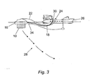
- FIG. 3 shows the floating subsea structure 10 and buoyancy element 16 next to the deployment vessel 26 following the removal of the transporting vessel 14.
- the buoyancy element 16 may include one or more sections, chambers or tanks able to be 'hybrid' tanks to accept the presence of buoyancy fluid and water, generally in a pre-determined and/or variable volume and/or ratio.
- buoyancy fluid having a density less than that of water and/or the use of water itself, allows the skilled man to very carefully control the buoyancy of the buoyancy element 16 to counter the weight of the subsea structure 10 and allow it to gently sink, preferably until the overall combination of the buoyancy element 16 and subsea structure 10 achieves neutral buoyancy at a position beneath the deployment vessel 26 as shown in Figure 4 .
- the submerged weight of the subsea structure 10 is reduced (by the use of the buoyancy element 16 containing a combination of water and sufficient low density incompressible buoyancy fluid), so as to be a maximum of 75% of the safe working capacity of the deployment winch 30.
- the mass of the subsea structure 10 has not been reduced and neither has its inertia.
- the winch 30 may therefore still comprise or be fitted with specific features, known in the art, to help control the size of dynamic peak loads expected in the fastening line 22 induced by the motions of the deployment vessel 26.
- FIGS 3 and 4 also show the use of an ROV (Remotely Operated Vehicle) 34 from the deployment vessel 26 to monitor and/or assist any and all movements of the subsea structure 10 and the buoyancy element 16.
- ROV Remote Operated Vehicle
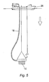
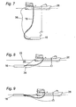
- the subsea structure 10 is beneath the deployment vessel 26 as shown in Figure 4 , the subsea structure 10 is ready for deployment to the sea bed (such as to an installation site) as shown in Figures 5 and 6 .
- Deployment of a subsea structure 10 from a deployment vessel 26 may be carried out by various methods known in the art, generally involving decreasing the buoyancy of one or more attachments to the subsea structure 10.
- buoyancy fluid out of the buoyancy element 16 back to the reservoir 30, and replacement therewith by water provides negative buoyancy to the buoyancy element 16 such that the subsea structure 10 is able to fall to the seabed 36 in a controlled manner.
- the launch or splashdown of the subsea structure 10 shown in Figure 2 occurs in a sheltered water site separate from the deployment site, and the subsea structure 10 and associated buoyancy element 16 are towed by the deployment vessel 26 to the deployment site prior to locating the subsea structure 10 beneath the deployment vessel 26 as shown by the path 28 in Figure 3 leading to Figure 4 .
Landscapes
- Engineering & Computer Science (AREA)
- Mechanical Engineering (AREA)
- Chemical & Material Sciences (AREA)
- Combustion & Propulsion (AREA)
- Ocean & Marine Engineering (AREA)
- Transportation (AREA)
- General Engineering & Computer Science (AREA)
- Civil Engineering (AREA)
- Structural Engineering (AREA)
- Earth Drilling (AREA)
- Bridges Or Land Bridges (AREA)
Description
- The present invention relates to a method for locating a subsea structure for deployment, generally for subsequent deployment to a seabed.
- The term "subsea structure" refers to any equipment, tool, machine, package, unit, device or other item or installation to be located and/or installed on or near a seabed, including but not limited to risers, underwater well-head elements in oil fields, manifolds, protection structures, fluid separation, pumping or processing units. Many of such structures are usually relatively 'large' and/or 'heavy'.
- Subsea structures that are intended to be installed on the seabed are usually manufactured onshore. Especially larger subsea structures are transported to a deployment site by towing them through the water behind a suitable vessel. At the deployment site, they are directly lowered from a deployment vessel to an installation site on the seabed.
WO 03/074353 A1 - Subsea structures of lesser size or weight can be transported on the deck of a suitable vessel or transportation barge to the deployment site, at which the subsea structure is then lifted off the vessel and into the sea for subsequent deployment. However, this requires the presence of a crane with usually heavy lifting capacity.
- PI 0306058-6A discloses a pendular method for installing equipment at the bottom of the sea, whereby the equipment can be transported on the deck of a first craft, and then swung like a pendulum until it is near the seabed.
- However, this results in an increased tension on the cable, and potentially a lack of control in the deployment, whilst not reducing in any way the load on the deployment winch.
- It is an object of the present invention to provide an improved method of locating a subsea structure for deployment to the seabed.
- Thus, according to a first aspect of the present invention, there is provided a method of locating a subsea structure beneath a floating deployment vessel for deployment to a seabed comprising at least the steps of:
- (a) transporting the subsea structure on a floating transporting vessel near to the deployment vessel;
- (b) lowering the transporting vessel to allow the subsea structure to float;
- (c) relocating either the transporting vessel or the subsea structure to allow the subsea structure to be separate of the transporting vessel; and
- (d) locating the subsea structure beneath the deployment vessel using one or more buoyancy elements with variable buoyancy.
- In this way, the subsea structure is safely transported to its site of deployment on a suitable floating vessel; it can be launched into the sea at a 'splashzone' without requiring a crane or other lifting mechanism; and then its location beneath the deployment vessel for subsequent deployment to the seabed can be controlled by the use of the one or more suitable buoyancy elements. The present invention therefore provides a controlled passage through the splashzone without the requirement for a crane, and can reduce the load on the deployment winch on a deployment vessel by modifying the net submerged weight of the subsea structure with the buoyancy element(s).
- The floating transporting vessel may be any suitable self-propelled ship able to move between a normal sea-faring/travelling/shipping position and a semi-submersible/submerged position. Such vessels are known in the art, for example from Dockwise Shipping B.V. Such vessels generally have an open-deck, and are able to be heavy transport sea and ocean-going vessels. A subsea structure can be located either directly on or next to a suitable deck of the floating transporting vessel, optionally on or within or in association with a suitable frame or cradle. The subsea structure can be 'sea-fastened' to the deck of such a vessel for transportation, and the fastenings for which can be released prior to the commencement of deployment.
- The floating transporting vessel transports the subsea structure near to the deployment vessel. This can include transport next to or otherwise sufficiently within the vicinity of the deployment vessel, preferably such that any umbilicals or cables or like required to be connected between the subsea structure and the deployment vessel can be connected at sea level.
- Once ready to launch at a 'splashzone', usually at or near the deployment site and near or next to the deployment vessel, the floating transporting vessel is able to semi-submerge, generally by the use of one or more buoyancy and/or ballast tanks therein, so as to still be floating, but to have at least a part of the transporting vessel, usually an open-deck, underwater.
- Once the transporting vessel is in its semi-submerged position, the subsea structure can float or be floated at or near sea level, either by itself or by being launched. The transporting vessel may include one or more assistant means such as cranes or winches to assist movement of the subsea structure in relation to the semi-submerged transporting vessel, especially once the subsea structure is able to float, but any such assistant means are not intended to be able to freely lift the subsea structure in air.
- The subsea structure may be associated with one or more buoyancy aids, one or more of which may be fitted onshore, at the deployment site and/or both, to assist its ability to float once the transporting vessel has been lowered to a semi-submerged position.
- Various buoyancy aids are known in the art. Generally it is preferred to use only one type or form of buoyancy aid to launch and deploy a subsea structure, due to the complexity of making any mechanical changes during such operations.
- Buoyancy aids in the form of one or more air tanks attached to a subsea structure are well known in the art, and are advantageous to reduce the apparent weight of the structure by increasing its buoyancy in water. Such buoyancy aids are used conventionally to reduce the load borne by use of a conventional crane to deploy a subsea structure, but they do not reduce the 'hook load' during lift of the subsea structure from the deck of a vessel, through the splashzone, and through deployment. Such tanks must also be strong enough to be capable of withstanding maximum external hydrostatic pressure without imploding or deforming due to the compressibility of the air contained therein, thus increasing the weight of the tanks and thereby reducing their buoyancy.
- In one embodiment of the present invention, the buoyancy aid comprises the one or more buoyancy elements with variable buoyancy of step (d).
- Preferably, the method of the present invention comprises the further step of providing at least one buoyancy element with variable buoyancy on or connected to the subsea structure during step (b). Optionally, one or more of such buoyancy elements are on or connected to the subsea structure onshore, and are transported to the splashdown and/or deployment site with the subsea structure by the transporting vessel.
- In the present invention, a buoyancy element with variable buoyancy may comprise any arrangement. Preferably, such buoyancy elements comprise one or more sections, parts, tanks and/or chambers able to contain at least a proportion of a buoyancy fluid comprising a wholly or substantially incompressible fluid having a density less than that of sea water. One or more chambers could be formed from a flexible or elastic material to permit the volume thereof to vary and accommodate the volume of buoyancy fluid contained therein.
- Varying the amount of buoyancy fluid in the buoyancy element(s) varies the overall buoyancy of the associated structure in a manner known in the art.
- An external reservoir of buoyancy fluid can be provided to vary the volume of buoyancy fluid within the or each buoyancy element, having the effect of varying the volume of said one or more chambers, etc.
- Such buoyancy elements can also contain air, and optionally also water, at varying times and varying proportions. For example, the or each chamber or tank, etc. could contain a bladder or diaphragm to allow such chamber(s) to simultaneously comprise buoyancy fluid and water, and also to allow the proportions of the buoyancy fluid and water in such chamber(s) to be varied, without allowing the two components to mix.
- Prior to submerging or submersion of the subsea structure, all chambers in the buoyancy element(s) are preferably fully vented of air and replaced with either the low-density incompressible buoyancy fluid and/or water.
- The substantially incompressible nature of the buoyancy fluid means that the buoyancy element can be made form relatively thin and light weight material compared to prior art air tanks, thus reducing the weight of the buoyancy elements and increasing the buoyancy thereof.
- Suitable buoyancy fluids include low molecular weight hydrocarbons such as methanol. In order to further reduce the density of the buoyancy fluid, glass microspheres may be added. Such fluids preferably have a density of between 500 and 600kg/m3 (the density of seawater being around 1027kg/m3). However any fluid having a density less than that of seawater may be suitable as the buoyancy fluid. Preferably the buoyancy fluid also has a low viscosity such that it is easily moveable (such as by one or more pumps) between the buoyancy element and an external reservoir, and such fluids include known low viscosity gels and the like.
- The use of one or more buoyancy aids, such as a buoyancy element described above, in association with the subsea structure, may assist the floating of the subsea structure at or near sea level following the lowering of the transporting vessel to its semi-submerged position. Following the floating of the subsea structure, there is relocation of either the floating vessel or the subsea structure (or both) to allow the subsea structure to be separate of the floating vessel. This may involve movement of the semi-submerged vessel, but usually involves the relocation of the floating subsea structure away from the transporting vessel such that the subsea structure is then floating 'free' of the location of the transporting vessel.
- Following the relocation of step (c), the transporting vessel can be fully re-floated in a manner known in the art, generally by the emptying of one or more of its ballast tanks.
- The launch or splashdown of the subsea structure may be separate or remote from the deployment site, and the subsea structure can then be towed the remaining distance to the deployment site. For example, it may be desired to launch the subsea structure in calmer or more sheltered seas, or in or at a calmer or more sheltered site, than occur at the deployment site. Thus, some relocation of the launched and now semi-submersed subsea structure may occur between steps (c) and (d) of the present invention.
- The subsea structure, and/or any associated buoyancy aids such as a buoyancy element, may include one or more guidelines or control lines to assist or control movement of the subsea structure in the sea, either as it floats at or near sea level, or during its subsequent movement, or both. Where the launch or splashdown of the subsea structure is separate from the deployment site, one guideline may be to partly, substantially or fully assist towing of the subsea structure to the deployment site.
- In one embodiment of the present invention, the subsea structure comprises a fastening line. During transportation of the subsea structure to the splashdown and/or deployment site, the fastening line may not be in use, or may be used to assist securing the subsea structure to the transporting vessel.
- The method of the present invention further comprises the step of securing a fastening line associated with the subsea structure to the deployment vessel at the deployment site. The securing of a fastening line to the deployment vessel may occur at any stage prior to, during or after step (b) and/or step (c), preferably prior to step (b), of the method of the present invention.
- Prior to step (d) of the method of the present invention, one or more buoyancy elements with variable buoyancy are associated with subsea structure. Such association may be by securement or attachment or other connection of the one or more buoyancy elements to the subsea structure, generally in or at a position above the subsea structure. Preferably, at least one such buoyancy element is associated with the subsea structure onshore, and remains associated with the subsea structure during steps (b) and (c) for use in step (d). The association between the buoyancy element(s) and the subsea structure is preferably designed or adapted to accommodate both tensile and compressive forces between the components, which can or may occur during the different phases of the deployment and landing operation. Preferably, the association is also designed or adapted to be remotely released by a Remotely Operated Vehicle (ROV) after the subsea structure is landed on a seabed or other intended working location to allow controlled recovery of the buoyancy element(s).
- A reservoir of buoyancy fluid for the or each buoyancy element may be located at any suitable location, including on one or more floating vessels such as independent storage vessels. By way of example only, one suitable location of a reservoir of buoyancy fluid is on the deployment vessel.
- Fluid communication is required between any such reservoir and the or each buoyancy element, and suitable fluid umbilicals for such fluid communication are well known in the art.
- Step (d) of the method of the present invention comprises locating the subsea structure beneath a deployment vessel, usually at the deployment site, using one or more buoyancy elements as described above. After step (c), and after any relocation to the deployment site, the subsea structure is floating at or near sea level near to the deployment vessel, and the or each buoyancy element provides control of the positioning of the subsea structure beneath the deployment vessel.
- The term "beneath a deployment vessel" as used herein includes the subsea structure being directly beneath the deployment vessel, generally by the connection through one or more generally vertical channels or ports in the deployment vessel, as well as next to or near to a side of the deployment vessel, optionally by the use of one more overhanging pulleys or winches or the like. The present invention is not limited by the exact position of the subsea structure beneath the deployment vessel in preparation for deployment by the deployment vessel, conventionally in a vertically downward direction, of the subsea structure to the seabed.
- PI 0306058-6A shows lowering of equipment from sea level to near the point of installation by the swinging pendulum movement of the equipment downwardly to the seabed. Such equipment undergoes sideward 'freefall' as it travels through the sea and thus creates increased strain on the installation cable.
- By the use of one or more buoyancy elements with variable buoyancy, the present invention is able to provide controlled location of the subsea structure from a floating sea level position, to a suitable position ready for deployment beneath the deployment vessel.
- In particular, by transferring buoyancy fluid in/out of the one or more buoyancy elements to vary the volume of buoyancy fluid in the or each buoyancy element, very close control of the overall buoyancy of the subsea structure can be provided so as to control the relocation of the subsea structure beneath the deployment vessel. In this way, careful and controlled lowering of the subsea structure from the sea level position to a position beneath the deployment vessel, can be carried out without any 'freefall', especially pendular freefall, and consequent strain on the fastening line therebetween.
- Varying the buoyancy of the or each buoyancy element associated with the subsea structure may involve the transferring of one or more of the elements: air, water (generally and preferably seawater) and buoyancy fluids; in, out, within, between, or any combination thereof; the one or more of the buoyancy elements. Means such as pumps, valves, lines, inlets and outlets of the or each buoyancy element are known in the art, and the skilled man is able to provide control of the presence and/or flow of the or each fluid so as to vary the buoyancy of the or each buoyancy element to provide controlled lowering or decent of the subsea structure from its floating sea level position to beneath the deployment vessel. Naturally, the subsea structure has a certain weight, such that the or each buoyancy element requires a certain degree of buoyancy to allow the subsea structure to float even at sea level. This can involve the inclusion of a proportion of air and/or buoyancy fluid in one or more chambers, sections, tanks, etc of the or each buoyancy element. Some water may also be included to prevent over-buoyancy.
- Preferably, prior to submersion of the subsea structure, all air is evacuated from the buoyancy element(s) and replaced by either water and/or buoyancy fluid, thus removing the requirement for the buoyancy element to be designed to accommodate a net external hydrostatic pressure. The transfer of buoyancy fluid and/or water to replace the air also reduces the overall buoyancy of the or each buoyancy element, providing careful control of the rate (and optionally position) of the lowering the subsea structure such that it can be slowly and carefully located beneath the deployment vessel.
- In a particular embodiment of the present invention, step (d) comprises a method of lowering a subsea structure to beneath the deployment vessel comprising the steps of:
- providing at least one buoyancy element on or connected to the subsea structure, said at least one buoyancy element comprising one or more chambers containing a buoyancy fluid comprising a substantially incompressible fluid having a density less than that of sea water;
- providing a reservoir for said buoyancy fluid at a location remote from said subsea structure;
- providing fluid communication between said reservoir and said one or more chambers of said at least one buoyancy element;
- transferring said buoyancy fluid between said reservoir and said one or more chambers of said at least one buoyancy element to vary the volume of buoyancy fluid within the at least one buoyancy element and thus vary the overall buoyancy of the subsea structure to thereby initiate and subsequently control the rate of descent of the subsea structure.
- Subsea structures can be deployed to an installation site, generally on the seabed, using a number of known methods. Generally, these involve the lowering of the subsea structure by means of a winch and fastening line from a floating deployment vessel directly beneath the vessel and in a controlled manner.
- The subsequent deployment of a subsea structure used in the present invention to the seabed may optionally but preferably continue to involve one or more of the buoyancy elements used in step (d), preferably by or involving at least partly the replacement of buoyancy fluid by water in a controlled manner to allow the subsequent lowering of the subsea structure beneath the deployment vessel to the seabed.
- Thus, according to a second aspect of the present invention, there is provided a method of locating a subsea structure beneath a floating deployment vessel as defined herein, and of deploying a subsea structure to a seabed comprising the steps of:
- (a) transporting the subsea structure on a floating transporting vessel near to a deployment vessel;
- (b) lowering the transportation vessel to allow the subsea structure to float;
- (c) relocating either the transporting vessel or the subsea structure to allow the subsea structure to be separate of the transporting vessel;
- (d) locating the subsea structure beneath the deployment vessel using one or more buoyancy elements with variable buoyancy; and
- (e) deploying the subsea structure from beneath the deployment vessel to the seabed.
- Preferably, step (e) comprises replacing buoyancy fluid in one or more of the buoyancy elements with water.
- Embodiments of the present invention will now be described by way of example only, and with reference to the accompanying diagrammatic drawings in which:
-
Figure 1 shows a first stage of a method of locating a subsea structure according to an embodiment of the present invention; -
Figure 2 shows a second stage of the method; -
Figure 3 show a third stage of the method; -
Figure 4 shows the location of a subsea structure beneath the deployment vessel; -
Figures 5 and6 show the deployment of the subsea structure to the seabed according to another embodiment of the present invention; -
Figures 7 to 9 show the recovery of a buoyancy element from the seabed. - The present invention provides an improved method for locating a subsea structure, especially a large subsea structure for use in oil and gas fields offshore, beneath a deployment vessel, and for subsequent deployment of the subsea structure to the seabed, such as to a deep water seabed location.
-
Figure 1 shows thesubsea structure 10 located on the open-deck 12 of a floating and sea-faring or sea-going transportingvessel 14, such as the known marine vessel "Sea Serpent". The transportingvessel 14 is able to transport thesubsea structure 10 from a dock or other onshore location (not shown) to near thedeployment vessel 26 already at a deployment site, or possibly at a more suitable, such as more sheltered, water location for the splashdown. -
Figure 1 shows the option of including abuoyancy element 16 attached to thesubsea structure 10. The attachment may occur onshore, or after thesubsea structure 10 has been located in the floatingvessel 14. Thebuoyancy element 16 could be in the form of a 'variable buoyancy submersible barge' (VBSB). - The
buoyancy element 16 may include one or more chambers (not shown) and one or morefluid umbilicals 18 able to provide fluid communication for transferring buoyancy fluid between thebuoyancy element 16 and a reservoir once required. During transporting of thesubsea structure 10 as shown inFigure 1 , the fluid umbilical 18 may not be required. -
Figure 1 also shows asupport guide 20 above thebuoyancy element 16, attached to afastening line 22. Thefastening line 22 may not be required during transporting of the subsea structure shown inFigure 1 . Thesupport guide 20 provides even support of thebuoyancy element 16 andsubsea structure 10 via thefastening line 22. - Once near the
deployment vessel 26, and possibly at or near the deployment site,Figure 2 shows the lowering of the transportingvessel 14 to a semi-submerged position, generally by the flooding of one or more ballast tanks therein in a manner known in the art. Preferably prior to the lowering of the transportingvessel 14, thefastening line 22 is connected to asuitable winch 24 on thenearby deployment vessel 26. Thefastening line 22 may pass through a vertical channel in thedeployment vessel 26 to reach thewinch 24. - Similarly, the fluid umbilical 18 is connected to a
suitable reservoir 30 on thedeployment vessel 26. Meanwhile, any fastenings or other securement of thesubsea structure 10 to the transportingvessel 14 can be detached and/or released. - As the transporting
vessel 14 semi-submerges, thesubsea structure 10 starts to float at or near thesea level 15, generally because of the buoyancy provided by thebuoyancy element 16. The skilled man will be aware of the amount of buoyancy required in thebuoyancy element 16 to achieve floating of thesubsea structure 10, and generally at least a portion, optionally substantially or all, of thebuoyancy element 16, may be air-filled at this time. - By use of the
fastening line 22 and/or one or more other guide or control elements not shown, the floatingsubsea structure 10 can be relocated gently away from the transportingvessel 14, whilst still floating at or near sea level. The energy required to relocate the floatingsubsea structure 10 is clearly substantially less than that required to vertically lift any subsea structure in the air by a crane over the side of a transporting vessel and into the sea. - Once the
subsea structure 10 andbuoyancy element 16 are 'free' of the transportingvessel 14, generally floating in a different sea area than the location of the transportingvessel 14, the transportingvessel 14 can be re-floated to its normal floating position, for re-use. -
Figure 3 shows the floatingsubsea structure 10 andbuoyancy element 16 next to thedeployment vessel 26 following the removal of the transportingvessel 14. By controlled transfer of: - (a) buoyancy fluid in the
reservoir 30 into thebuoyancy element 16, optionally into one or more parts, sections, tanks or chambers therein, and distributed therein in an equitable manner; and/or - (b) water, generally being sea water, through one or more inlets (not shown) into the
buoyancy element 16 in a manner known in the art; - The
buoyancy element 16 may include one or more sections, chambers or tanks able to be 'hybrid' tanks to accept the presence of buoyancy fluid and water, generally in a pre-determined and/or variable volume and/or ratio. - The use of buoyancy fluid having a density less than that of water and/or the use of water itself, allows the skilled man to very carefully control the buoyancy of the
buoyancy element 16 to counter the weight of thesubsea structure 10 and allow it to gently sink, preferably until the overall combination of thebuoyancy element 16 andsubsea structure 10 achieves neutral buoyancy at a position beneath thedeployment vessel 26 as shown inFigure 4 . - Preferably, the submerged weight of the
subsea structure 10 is reduced (by the use of thebuoyancy element 16 containing a combination of water and sufficient low density incompressible buoyancy fluid), so as to be a maximum of 75% of the safe working capacity of thedeployment winch 30. However, whilst the submerged weight of thesubsea structure 10 has been reduced, the mass of thesubsea structure 10 has not been reduced and neither has its inertia. Thewinch 30 may therefore still comprise or be fitted with specific features, known in the art, to help control the size of dynamic peak loads expected in thefastening line 22 induced by the motions of thedeployment vessel 26. -
Figures 3 and4 also show the use of an ROV (Remotely Operated Vehicle) 34 from thedeployment vessel 26 to monitor and/or assist any and all movements of thesubsea structure 10 and thebuoyancy element 16. - Once the
subsea structure 10 is beneath thedeployment vessel 26 as shown inFigure 4 , thesubsea structure 10 is ready for deployment to the sea bed (such as to an installation site) as shown inFigures 5 and6 . - Deployment of a
subsea structure 10 from adeployment vessel 26 may be carried out by various methods known in the art, generally involving decreasing the buoyancy of one or more attachments to thesubsea structure 10. - In an embodiment of the present invention, further transfer of buoyancy fluid out of the
buoyancy element 16 back to thereservoir 30, and replacement therewith by water, provides negative buoyancy to thebuoyancy element 16 such that thesubsea structure 10 is able to fall to theseabed 36 in a controlled manner. - The removal of the
buoyancy element 16 from thesubsea structure 10 once located on theseabed 36, and the recovery of thebuoyancy element 16 to thesea surface 15, are shown inFigures 7 to 9 . A towing line orpennant 38 can be attached to thebuoyancy element 16, and the reverse of some of the steps mentioned hereinabove can occur to increase under control the buoyancy of thebuoyancy element 16 to thesea surface 15. - Various modifications and variations to the described embodiments of the invention will be apparent to those skilled in the art without departing from the scope of the invention as defined herein. Although the invention has been described in connection with specific preferred embodiments it should be understood that the invention as defined herein should not be unduly limited to such specific embodiments.
- For example, in one alternative arrangement, the launch or splashdown of the
subsea structure 10 shown inFigure 2 occurs in a sheltered water site separate from the deployment site, and thesubsea structure 10 and associatedbuoyancy element 16 are towed by thedeployment vessel 26 to the deployment site prior to locating thesubsea structure 10 beneath thedeployment vessel 26 as shown by thepath 28 inFigure 3 leading toFigure 4 .
Claims (25)
- A method of locating a subsea structure (10) beneath a floating deployment vessel (26) for deployment to a seabed (36) comprising at least the steps of:(a) transporting the subsea structure (10) on a floating transporting vessel (14) near to the deployment vessel (26);(b) lowering the transporting vessel (14) to allow the subsea structure (10) to float;(c) relocating either the transporting vessel (14) or the subsea structure (10) to allow the subsea structure to be separate of the transporting vessel; and(d) locating the subsea structure (10) beneath the deployment vessel (26) using one or more buoyancy elements (16) with variable buoyancy.
- A method as claimed in claim 1 wherein the floating transporting vessel (14) is moveable in step (b) between a sea-faring position and a semi-submerged position.
- A method as claimed in claim 1 or claim 2 wherein the subsea structure (10) is located in step (a) directly on or next to a deck (12) of the floating transporting vessel (14).
- A method as claimed in any one of the preceding claims further comprising the step of providing at least one buoyancy element (16) with variable buoyancy on or connected to the subsea structure (10) prior to or during step (b).
- A method as claimed in claim 4 wherein the at least one buoyancy element (16) is on or connected to the subsea structure (10) onshore and/or prior to step (a).
- A method as claimed in claim 4 or claim 5 wherein the at least one buoyancy element (16) is connected to the subsea structure (10) onshore, and remains associated with the subsea structure during steps (b) and (c) for use in step (d).
- A method as claimed in any one of the preceding claims wherein the one or more buoyancy elements (16) with variable buoyancy are secured to the subsea structure (10) in or at a position above the subsea structure.
- A method as claimed in any one of the preceding claims wherein the or each buoyancy element (16) comprises one or more chambers able to contain at least a proportion of a buoyancy fluid.
- A method as claimed in claim 8 wherein one or more of the chambers are formed from a flexible or elastic material to permit the volume thereof to vary and accommodate the volume of buoyancy fluid contained therein.
- A method as claimed in claim 8 or claim 9 wherein the buoyancy fluid comprises a wholly or substantially incompressible fluid having a density less than that of sea water.
- A method as claimed in claim 10 wherein the buoyancy fluid is a low molecular weight hydrocarbon such as methanol.
- A method as claimed in any one of claims 8 to 11 wherein the buoyancy fluid includes glass microspheres.
- A method as claimed in any one of claims 8 to 12 wherein the buoyancy fluid has a density of between 500 and 600kg/m3.
- A method as claimed in any one of claims 8 to 13 wherein the buoyancy fluid is a low viscosity gel.
- A method as claimed in any one of claims 8 to 14 further comprising the step of varying the volume of buoyancy fluid within the or each buoyancy element (16) to vary the overall buoyancy of the subsea structure (10).
- A method as claimed in any one of claims 8 to 15 further comprising providing an external reservoir of buoyancy fluid and transferring buoyancy fluid between the external reservoir and the or each buoyancy element (16).
- A method as claimed in any one of claims 8 to 16 wherein the or each chamber includes a bladder or diaphragm to allow the chamber(s) to simultaneously comprise buoyancy fluid and water, preferably to allow the proportions of the buoyancy fluid and water in such chamber(s) to be varied, without allowing the two components to mix.
- A method as claimed in any one of the preceding claims comprising varying the buoyancy of the or each buoyancy element (16) associated with the subsea structure (10) by transferring of one or more of the elements: air, water, preferably seawater, and buoyancy fluids; in, out, within, between or any combination thereof; the one or more of the buoyancy elements.
- A method as claimed in any one of the preceding claims wherein prior to step (b), the buoyancy element(s) (16) are fully vented of air and replaced with either buoyancy fluid as defined in any one of claims 10 to 14 and/or water.
- A method as claimed in any one of the preceding claims comprising the further transporting of the floating subsea structure (10) at or near sealevel between steps (c) and (d).
- A method as claimed in any one of the preceding claims including the steps of:providing at least one buoyancy element (16) on or connected to the subsea structure (10), said at least one buoyancy element comprising one or more chambers containing a buoyancy fluid comprising a substantially incompressible fluid having a density less than that of sea water;providing a reservoir for said buoyancy fluid at a location remote from said subsea structure;providing fluid communication between said reservoir and said one or more chambers of said at least one buoyancy element;transferring said buoyancy fluid between said reservoir and said one or more chambers of said at least one buoyancy element to vary the volume of buoyancy fluid within the at least one buoyancy element and thus vary the overall buoyancy of the subsea structure to control the rate of descent of the subsea structure to beneath the deployment vessel (26).
- A method as claimed in any one of the preceding claims wherein the subsea structure (10) is subsequently deployed to an installation site on the seabed (36) beneath the floating deployment vessel (26).
- A method as claimed in any one of the preceding claims wherein the subsequent deployment of a subsea structure (10) to the seabed (36) involves the one or more of the buoyancy elements (16) used in step (d), preferably by or involving at least partly the replacement of buoyancy fluid in the buoyancy element(s) by water.
- A method of locating a subsea structure beneath a floating deployment vessel as claimed in any one of the preceding claims and of deploying the subsea structure to a seabed comprising the steps of:(a) transporting the subsea structure on a floating transporting vessel near to a deployment vessel;(b) lowering the transportation vessel to allow the subsea structure to float;(c) relocating either the transporting vessel or the subsea structure to allow the subsea structure to be separate of the transporting vessel;(d) locating the subsea structure beneath the deployment vessel using one or more buoyancy elements with variable buoyancy; and(e) deploying the subsea structure from beneath the deployment vessel to the seabed.
- A method as claimed in claim 24 wherein step (e) comprises replacing buoyancy fluid in one or more of the buoyancy elements with water.
Applications Claiming Priority (2)
| Application Number | Priority Date | Filing Date | Title |
|---|---|---|---|
| GB0817361.9A GB2463697B (en) | 2008-09-22 | 2008-09-22 | Method of locating a subsea structure for deployment |
| PCT/GB2009/051110 WO2010032027A2 (en) | 2008-09-22 | 2009-09-03 | Method of locating a subsea structure for deployment |
Publications (2)
| Publication Number | Publication Date |
|---|---|
| EP2326552A2 EP2326552A2 (en) | 2011-06-01 |
| EP2326552B1 true EP2326552B1 (en) | 2013-11-13 |
Family
ID=39952016
Family Applications (1)
| Application Number | Title | Priority Date | Filing Date |
|---|---|---|---|
| EP09785569.6A Not-in-force EP2326552B1 (en) | 2008-09-22 | 2009-09-03 | Method of locating a subsea structure for deployment |
Country Status (7)
| Country | Link |
|---|---|
| US (1) | US20110206465A1 (en) |
| EP (1) | EP2326552B1 (en) |
| AU (1) | AU2009294382B2 (en) |
| BR (1) | BRPI0919217A2 (en) |
| GB (1) | GB2463697B (en) |
| MY (1) | MY152396A (en) |
| WO (1) | WO2010032027A2 (en) |
Cited By (1)
| Publication number | Priority date | Publication date | Assignee | Title |
|---|---|---|---|---|
| CN105059484A (en) * | 2015-08-11 | 2015-11-18 | 山东省海洋仪器仪表科技中心 | Boarding and disembarking operation mode for large ocean structure |
Families Citing this family (10)
| Publication number | Priority date | Publication date | Assignee | Title |
|---|---|---|---|---|
| GB2464714B (en) | 2008-10-24 | 2010-09-08 | Subsea Deployment Systems Ltd | Method and apparatus for subsea installations |
| US20120260839A1 (en) * | 2010-01-05 | 2012-10-18 | Horton Wison Deepwater, Inc. | Systems and methods for subsea gas storage installation and removal |
| DE102010033788A1 (en) * | 2010-08-09 | 2012-02-09 | Voith Patent Gmbh | Method and apparatus for installing a tented power plant |
| GB201015218D0 (en) * | 2010-09-13 | 2010-10-27 | Aubin Ltd | Method |
| US9156609B2 (en) * | 2013-04-06 | 2015-10-13 | Safe Marine Transfer, LLC | Large subsea package deployment methods and devices |
| GB2532028B (en) | 2014-11-05 | 2017-07-26 | Subsea 7 Norway As | Transportation and installation of heavy subsea structures |
| ES2975177T3 (en) * | 2017-04-14 | 2024-07-03 | Safe Marine Transfer Llc | Procedure and apparatus for installing, adjusting and recovering flotation elements of underwater installations |
| US10781670B1 (en) * | 2019-10-10 | 2020-09-22 | Trendsetter Engineering, Inc. | Process for non-vertical installation and removal of a subsea structure |
| CN111645810B (en) * | 2020-06-16 | 2021-05-28 | 中国船舶科学研究中心 | A multifunctional work boat with a buoyancy adjustment carrying platform and its operation method |
| CN115230895B (en) * | 2022-09-22 | 2022-12-30 | 青岛黄海学院 | Ocean platform with overturn preventing device and working method thereof |
Family Cites Families (14)
| Publication number | Priority date | Publication date | Assignee | Title |
|---|---|---|---|---|
| CA871441A (en) * | 1971-05-25 | F. Manning William | Underwater self-adjusting tripod support structure | |
| FR2391900A1 (en) * | 1977-05-26 | 1978-12-22 | Inst Francais Du Petrole | METHOD FOR IMMERSING A NEGATIVE BUOYANCY DEVICE |
| US4797035A (en) * | 1987-06-05 | 1989-01-10 | Conoco Inc. | Method of installing a template on the seafloor |
| NO172483C (en) * | 1990-08-14 | 1993-07-28 | Norwegian Contractors | PROCEDURE AND DEVICE FOR MANAGED SUBMISSION AND LOCATION OF A LARGE HEAVY SUBMISSION ITEMS DOWN THE SEA |
| US5190107A (en) * | 1991-04-23 | 1993-03-02 | Shell Oil Company | Heave compensated support system for positioning subsea work packages |
| US20020185188A1 (en) * | 2001-04-27 | 2002-12-12 | Quigley Peter A. | Composite tubing |
| US6688930B2 (en) * | 2001-05-22 | 2004-02-10 | Fmc Technologies, Inc. | Hybrid buoyant riser/tension mooring system |
| WO2002098725A2 (en) * | 2001-06-01 | 2002-12-12 | The Johns Hopkins University | Telescoping spar platform and method of using same |
| NO316168B1 (en) * | 2002-03-06 | 2003-12-22 | Aker Marine Contractors As | Procedure for transporting and installing objects at sea |
| FR2852917B1 (en) * | 2003-03-26 | 2005-06-24 | Saipem Sa | SEALED COMPARTMENT RECEPTACLE AND METHOD OF PLACING IT TO RECOVER POLLUTANT EFFLUENTS FROM A EPAVE |
| BR0306058B1 (en) * | 2003-12-18 | 2012-06-12 | Pendular method for installation of equipment under the sea in offshore operations. | |
| US7963721B2 (en) * | 2004-09-21 | 2011-06-21 | Kellogg Brown & Root Llc | Distributed buoyancy subsea pipeline apparatus and method |
| NL1029995C1 (en) * | 2005-09-21 | 2007-03-22 | Dockwise Shipping B V | Movable floating cabinet. |
| GB0615884D0 (en) * | 2006-08-10 | 2006-09-20 | Subsea 7 Ltd | Method and frame |
-
2008
- 2008-09-22 GB GB0817361.9A patent/GB2463697B/en not_active Expired - Fee Related
-
2009
- 2009-09-03 WO PCT/GB2009/051110 patent/WO2010032027A2/en not_active Ceased
- 2009-09-03 AU AU2009294382A patent/AU2009294382B2/en not_active Ceased
- 2009-09-03 MY MYPI20110957 patent/MY152396A/en unknown
- 2009-09-03 EP EP09785569.6A patent/EP2326552B1/en not_active Not-in-force
- 2009-09-03 BR BRPI0919217A patent/BRPI0919217A2/en not_active IP Right Cessation
- 2009-09-03 US US13/061,987 patent/US20110206465A1/en not_active Abandoned
Cited By (1)
| Publication number | Priority date | Publication date | Assignee | Title |
|---|---|---|---|---|
| CN105059484A (en) * | 2015-08-11 | 2015-11-18 | 山东省海洋仪器仪表科技中心 | Boarding and disembarking operation mode for large ocean structure |
Also Published As
| Publication number | Publication date |
|---|---|
| US20110206465A1 (en) | 2011-08-25 |
| AU2009294382A1 (en) | 2010-03-25 |
| WO2010032027A3 (en) | 2011-03-24 |
| WO2010032027A2 (en) | 2010-03-25 |
| GB0817361D0 (en) | 2008-10-29 |
| BRPI0919217A2 (en) | 2015-12-08 |
| GB2463697B (en) | 2012-06-27 |
| EP2326552A2 (en) | 2011-06-01 |
| MY152396A (en) | 2014-09-15 |
| GB2463697A (en) | 2010-03-24 |
| AU2009294382B2 (en) | 2014-06-26 |
Similar Documents
| Publication | Publication Date | Title |
|---|---|---|
| EP2326552B1 (en) | Method of locating a subsea structure for deployment | |
| AU2009306155B2 (en) | Method and apparatus for subsea installations | |
| EP1984237B1 (en) | Deep water installation vessel | |
| CN102132001B (en) | Installation or removal of subsea structures | |
| US10890051B2 (en) | Handling heavy subsea structures | |
| CN102753759B (en) | Method for lifting an underwater structure and method for installing an underwater structure | |
| EP2903916B1 (en) | Tank | |
| US20210163108A1 (en) | Subsea installation method and assembly | |
| GB2466377A (en) | Method of manipulating the buoyancy of a device | |
| WO2009063159A1 (en) | Method and apparatus for lowering a subsea structure between the surface and the seabed | |
| KR101707412B1 (en) | Subsea Bridge System | |
| Sablok et al. | Disconnectable arctic spar | |
| WO2018152106A1 (en) | Submersible autonomous barge |
Legal Events
| Date | Code | Title | Description |
|---|---|---|---|
| PUAI | Public reference made under article 153(3) epc to a published international application that has entered the european phase |
Free format text: ORIGINAL CODE: 0009012 |
|
| 17P | Request for examination filed |
Effective date: 20110218 |
|
| AK | Designated contracting states |
Kind code of ref document: A2 Designated state(s): AT BE BG CH CY CZ DE DK EE ES FI FR GB GR HR HU IE IS IT LI LT LU LV MC MK MT NL NO PL PT RO SE SI SK SM TR |
|
| AX | Request for extension of the european patent |
Extension state: AL BA RS |
|
| RIN1 | Information on inventor provided before grant (corrected) |
Inventor name: SMITH, RICHARD Inventor name: PRESLEY, BARRY Inventor name: HOWARD, BRETT |
|
| DAX | Request for extension of the european patent (deleted) | ||
| GRAP | Despatch of communication of intention to grant a patent |
Free format text: ORIGINAL CODE: EPIDOSNIGR1 |
|
| INTG | Intention to grant announced |
Effective date: 20130514 |
|
| GRAS | Grant fee paid |
Free format text: ORIGINAL CODE: EPIDOSNIGR3 |
|
| GRAA | (expected) grant |
Free format text: ORIGINAL CODE: 0009210 |
|
| AK | Designated contracting states |
Kind code of ref document: B1 Designated state(s): AT BE BG CH CY CZ DE DK EE ES FI FR GB GR HR HU IE IS IT LI LT LU LV MC MK MT NL NO PL PT RO SE SI SK SM TR |
|
| REG | Reference to a national code |
Ref country code: GB Ref legal event code: FG4D |
|
| REG | Reference to a national code |
Ref country code: CH Ref legal event code: EP |
|
| REG | Reference to a national code |
Ref country code: AT Ref legal event code: REF Ref document number: 640452 Country of ref document: AT Kind code of ref document: T Effective date: 20131215 |
|
| REG | Reference to a national code |
Ref country code: IE Ref legal event code: FG4D |
|
| REG | Reference to a national code |
Ref country code: DE Ref legal event code: R096 Ref document number: 602009020110 Country of ref document: DE Effective date: 20140109 |
|
| REG | Reference to a national code |
Ref country code: NL Ref legal event code: VDEP Effective date: 20131113 |
|
| REG | Reference to a national code |
Ref country code: NO Ref legal event code: T2 Effective date: 20131113 |
|
| REG | Reference to a national code |
Ref country code: AT Ref legal event code: MK05 Ref document number: 640452 Country of ref document: AT Kind code of ref document: T Effective date: 20131113 |
|
| REG | Reference to a national code |
Ref country code: LT Ref legal event code: MG4D |
|
| PG25 | Lapsed in a contracting state [announced via postgrant information from national office to epo] |
Ref country code: IS Free format text: LAPSE BECAUSE OF FAILURE TO SUBMIT A TRANSLATION OF THE DESCRIPTION OR TO PAY THE FEE WITHIN THE PRESCRIBED TIME-LIMIT Effective date: 20140313 Ref country code: LT Free format text: LAPSE BECAUSE OF FAILURE TO SUBMIT A TRANSLATION OF THE DESCRIPTION OR TO PAY THE FEE WITHIN THE PRESCRIBED TIME-LIMIT Effective date: 20131113 Ref country code: FI Free format text: LAPSE BECAUSE OF FAILURE TO SUBMIT A TRANSLATION OF THE DESCRIPTION OR TO PAY THE FEE WITHIN THE PRESCRIBED TIME-LIMIT Effective date: 20131113 Ref country code: SE Free format text: LAPSE BECAUSE OF FAILURE TO SUBMIT A TRANSLATION OF THE DESCRIPTION OR TO PAY THE FEE WITHIN THE PRESCRIBED TIME-LIMIT Effective date: 20131113 Ref country code: NL Free format text: LAPSE BECAUSE OF FAILURE TO SUBMIT A TRANSLATION OF THE DESCRIPTION OR TO PAY THE FEE WITHIN THE PRESCRIBED TIME-LIMIT Effective date: 20131113 Ref country code: HR Free format text: LAPSE BECAUSE OF FAILURE TO SUBMIT A TRANSLATION OF THE DESCRIPTION OR TO PAY THE FEE WITHIN THE PRESCRIBED TIME-LIMIT Effective date: 20131113 |
|
| PG25 | Lapsed in a contracting state [announced via postgrant information from national office to epo] |
Ref country code: ES Free format text: LAPSE BECAUSE OF FAILURE TO SUBMIT A TRANSLATION OF THE DESCRIPTION OR TO PAY THE FEE WITHIN THE PRESCRIBED TIME-LIMIT Effective date: 20131113 Ref country code: LV Free format text: LAPSE BECAUSE OF FAILURE TO SUBMIT A TRANSLATION OF THE DESCRIPTION OR TO PAY THE FEE WITHIN THE PRESCRIBED TIME-LIMIT Effective date: 20131113 Ref country code: BE Free format text: LAPSE BECAUSE OF FAILURE TO SUBMIT A TRANSLATION OF THE DESCRIPTION OR TO PAY THE FEE WITHIN THE PRESCRIBED TIME-LIMIT Effective date: 20131113 Ref country code: CY Free format text: LAPSE BECAUSE OF FAILURE TO SUBMIT A TRANSLATION OF THE DESCRIPTION OR TO PAY THE FEE WITHIN THE PRESCRIBED TIME-LIMIT Effective date: 20131113 Ref country code: AT Free format text: LAPSE BECAUSE OF FAILURE TO SUBMIT A TRANSLATION OF THE DESCRIPTION OR TO PAY THE FEE WITHIN THE PRESCRIBED TIME-LIMIT Effective date: 20131113 |
|
| PG25 | Lapsed in a contracting state [announced via postgrant information from national office to epo] |
Ref country code: PT Free format text: LAPSE BECAUSE OF FAILURE TO SUBMIT A TRANSLATION OF THE DESCRIPTION OR TO PAY THE FEE WITHIN THE PRESCRIBED TIME-LIMIT Effective date: 20140313 |
|
| PG25 | Lapsed in a contracting state [announced via postgrant information from national office to epo] |
Ref country code: EE Free format text: LAPSE BECAUSE OF FAILURE TO SUBMIT A TRANSLATION OF THE DESCRIPTION OR TO PAY THE FEE WITHIN THE PRESCRIBED TIME-LIMIT Effective date: 20131113 |
|
| REG | Reference to a national code |
Ref country code: DE Ref legal event code: R097 Ref document number: 602009020110 Country of ref document: DE |
|
| PG25 | Lapsed in a contracting state [announced via postgrant information from national office to epo] |
Ref country code: PL Free format text: LAPSE BECAUSE OF FAILURE TO SUBMIT A TRANSLATION OF THE DESCRIPTION OR TO PAY THE FEE WITHIN THE PRESCRIBED TIME-LIMIT Effective date: 20131113 Ref country code: SK Free format text: LAPSE BECAUSE OF FAILURE TO SUBMIT A TRANSLATION OF THE DESCRIPTION OR TO PAY THE FEE WITHIN THE PRESCRIBED TIME-LIMIT Effective date: 20131113 Ref country code: CZ Free format text: LAPSE BECAUSE OF FAILURE TO SUBMIT A TRANSLATION OF THE DESCRIPTION OR TO PAY THE FEE WITHIN THE PRESCRIBED TIME-LIMIT Effective date: 20131113 Ref country code: RO Free format text: LAPSE BECAUSE OF FAILURE TO SUBMIT A TRANSLATION OF THE DESCRIPTION OR TO PAY THE FEE WITHIN THE PRESCRIBED TIME-LIMIT Effective date: 20131113 |
|
| PLBE | No opposition filed within time limit |
Free format text: ORIGINAL CODE: 0009261 |
|
| STAA | Information on the status of an ep patent application or granted ep patent |
Free format text: STATUS: NO OPPOSITION FILED WITHIN TIME LIMIT |
|
| PG25 | Lapsed in a contracting state [announced via postgrant information from national office to epo] |
Ref country code: DK Free format text: LAPSE BECAUSE OF FAILURE TO SUBMIT A TRANSLATION OF THE DESCRIPTION OR TO PAY THE FEE WITHIN THE PRESCRIBED TIME-LIMIT Effective date: 20131113 |
|
| 26N | No opposition filed |
Effective date: 20140814 |
|
| REG | Reference to a national code |
Ref country code: DE Ref legal event code: R097 Ref document number: 602009020110 Country of ref document: DE Effective date: 20140814 |
|
| PG25 | Lapsed in a contracting state [announced via postgrant information from national office to epo] |
Ref country code: SI Free format text: LAPSE BECAUSE OF FAILURE TO SUBMIT A TRANSLATION OF THE DESCRIPTION OR TO PAY THE FEE WITHIN THE PRESCRIBED TIME-LIMIT Effective date: 20131113 |
|
| REG | Reference to a national code |
Ref country code: DE Ref legal event code: R119 Ref document number: 602009020110 Country of ref document: DE |
|
| PG25 | Lapsed in a contracting state [announced via postgrant information from national office to epo] |
Ref country code: MC Free format text: LAPSE BECAUSE OF FAILURE TO SUBMIT A TRANSLATION OF THE DESCRIPTION OR TO PAY THE FEE WITHIN THE PRESCRIBED TIME-LIMIT Effective date: 20131113 Ref country code: LU Free format text: LAPSE BECAUSE OF FAILURE TO SUBMIT A TRANSLATION OF THE DESCRIPTION OR TO PAY THE FEE WITHIN THE PRESCRIBED TIME-LIMIT Effective date: 20140903 |
|
| REG | Reference to a national code |
Ref country code: CH Ref legal event code: PL |
|
| REG | Reference to a national code |
Ref country code: IE Ref legal event code: MM4A |
|
| REG | Reference to a national code |
Ref country code: DE Ref legal event code: R119 Ref document number: 602009020110 Country of ref document: DE Effective date: 20150401 |
|
| PG25 | Lapsed in a contracting state [announced via postgrant information from national office to epo] |
Ref country code: CH Free format text: LAPSE BECAUSE OF NON-PAYMENT OF DUE FEES Effective date: 20140930 Ref country code: DE Free format text: LAPSE BECAUSE OF NON-PAYMENT OF DUE FEES Effective date: 20150401 Ref country code: LI Free format text: LAPSE BECAUSE OF NON-PAYMENT OF DUE FEES Effective date: 20140930 |
|
| PG25 | Lapsed in a contracting state [announced via postgrant information from national office to epo] |
Ref country code: IT Free format text: LAPSE BECAUSE OF FAILURE TO SUBMIT A TRANSLATION OF THE DESCRIPTION OR TO PAY THE FEE WITHIN THE PRESCRIBED TIME-LIMIT Effective date: 20131113 Ref country code: IE Free format text: LAPSE BECAUSE OF NON-PAYMENT OF DUE FEES Effective date: 20140903 |
|
| PG25 | Lapsed in a contracting state [announced via postgrant information from national office to epo] |
Ref country code: SM Free format text: LAPSE BECAUSE OF FAILURE TO SUBMIT A TRANSLATION OF THE DESCRIPTION OR TO PAY THE FEE WITHIN THE PRESCRIBED TIME-LIMIT Effective date: 20131113 |
|
| PG25 | Lapsed in a contracting state [announced via postgrant information from national office to epo] |
Ref country code: BG Free format text: LAPSE BECAUSE OF FAILURE TO SUBMIT A TRANSLATION OF THE DESCRIPTION OR TO PAY THE FEE WITHIN THE PRESCRIBED TIME-LIMIT Effective date: 20131113 Ref country code: GR Free format text: LAPSE BECAUSE OF FAILURE TO SUBMIT A TRANSLATION OF THE DESCRIPTION OR TO PAY THE FEE WITHIN THE PRESCRIBED TIME-LIMIT Effective date: 20140214 Ref country code: MT Free format text: LAPSE BECAUSE OF FAILURE TO SUBMIT A TRANSLATION OF THE DESCRIPTION OR TO PAY THE FEE WITHIN THE PRESCRIBED TIME-LIMIT Effective date: 20131113 |
|
| PG25 | Lapsed in a contracting state [announced via postgrant information from national office to epo] |
Ref country code: HU Free format text: LAPSE BECAUSE OF FAILURE TO SUBMIT A TRANSLATION OF THE DESCRIPTION OR TO PAY THE FEE WITHIN THE PRESCRIBED TIME-LIMIT; INVALID AB INITIO Effective date: 20090903 Ref country code: TR Free format text: LAPSE BECAUSE OF FAILURE TO SUBMIT A TRANSLATION OF THE DESCRIPTION OR TO PAY THE FEE WITHIN THE PRESCRIBED TIME-LIMIT Effective date: 20131113 |
|
| REG | Reference to a national code |
Ref country code: FR Ref legal event code: PLFP Year of fee payment: 8 |
|
| PGFP | Annual fee paid to national office [announced via postgrant information from national office to epo] |
Ref country code: GB Payment date: 20160916 Year of fee payment: 8 Ref country code: NO Payment date: 20160826 Year of fee payment: 8 |
|
| PGFP | Annual fee paid to national office [announced via postgrant information from national office to epo] |
Ref country code: FR Payment date: 20160927 Year of fee payment: 8 |
|
| REG | Reference to a national code |
Ref country code: NO Ref legal event code: MMEP |
|
| GBPC | Gb: european patent ceased through non-payment of renewal fee |
Effective date: 20170903 |
|
| PG25 | Lapsed in a contracting state [announced via postgrant information from national office to epo] |
Ref country code: MK Free format text: LAPSE BECAUSE OF FAILURE TO SUBMIT A TRANSLATION OF THE DESCRIPTION OR TO PAY THE FEE WITHIN THE PRESCRIBED TIME-LIMIT Effective date: 20131113 |
|
| REG | Reference to a national code |
Ref country code: FR Ref legal event code: ST Effective date: 20180531 |
|
| PG25 | Lapsed in a contracting state [announced via postgrant information from national office to epo] |
Ref country code: NO Free format text: LAPSE BECAUSE OF NON-PAYMENT OF DUE FEES Effective date: 20170930 Ref country code: GB Free format text: LAPSE BECAUSE OF NON-PAYMENT OF DUE FEES Effective date: 20170903 |
|
| PG25 | Lapsed in a contracting state [announced via postgrant information from national office to epo] |
Ref country code: FR Free format text: LAPSE BECAUSE OF NON-PAYMENT OF DUE FEES Effective date: 20171002 |