EP2325822B1 - Système d'alerte avec zonage utilisant des détecteurs portables sans fil et une station centrale - Google Patents
Système d'alerte avec zonage utilisant des détecteurs portables sans fil et une station centrale Download PDFInfo
- Publication number
- EP2325822B1 EP2325822B1 EP10191385A EP10191385A EP2325822B1 EP 2325822 B1 EP2325822 B1 EP 2325822B1 EP 10191385 A EP10191385 A EP 10191385A EP 10191385 A EP10191385 A EP 10191385A EP 2325822 B1 EP2325822 B1 EP 2325822B1
- Authority
- EP
- European Patent Office
- Prior art keywords
- zones
- zone
- central station
- wireless devices
- active
- Prior art date
- Legal status (The legal status is an assumption and is not a legal conclusion. Google has not performed a legal analysis and makes no representation as to the accuracy of the status listed.)
- Active
Links
- 238000013316 zoning Methods 0.000 title description 7
- 238000000034 method Methods 0.000 claims description 27
- 230000002452 interceptive effect Effects 0.000 claims description 11
- 230000006854 communication Effects 0.000 claims description 9
- 238000004891 communication Methods 0.000 claims description 9
- 238000012544 monitoring process Methods 0.000 claims description 6
- 238000012790 confirmation Methods 0.000 claims description 4
- 230000007175 bidirectional communication Effects 0.000 claims description 2
- 238000010586 diagram Methods 0.000 description 10
- 239000000779 smoke Substances 0.000 description 4
- 230000002457 bidirectional effect Effects 0.000 description 2
- 230000001413 cellular effect Effects 0.000 description 2
- 230000005540 biological transmission Effects 0.000 description 1
- 238000004883 computer application Methods 0.000 description 1
- 238000001514 detection method Methods 0.000 description 1
Images


Classifications
-
- G—PHYSICS
- G08—SIGNALLING
- G08B—SIGNALLING OR CALLING SYSTEMS; ORDER TELEGRAPHS; ALARM SYSTEMS
- G08B25/00—Alarm systems in which the location of the alarm condition is signalled to a central station, e.g. fire or police telegraphic systems
- G08B25/01—Alarm systems in which the location of the alarm condition is signalled to a central station, e.g. fire or police telegraphic systems characterised by the transmission medium
- G08B25/016—Personal emergency signalling and security systems
-
- G—PHYSICS
- G08—SIGNALLING
- G08B—SIGNALLING OR CALLING SYSTEMS; ORDER TELEGRAPHS; ALARM SYSTEMS
- G08B21/00—Alarms responsive to a single specified undesired or abnormal condition and not otherwise provided for
- G08B21/02—Alarms for ensuring the safety of persons
-
- G—PHYSICS
- G08—SIGNALLING
- G08B—SIGNALLING OR CALLING SYSTEMS; ORDER TELEGRAPHS; ALARM SYSTEMS
- G08B25/00—Alarm systems in which the location of the alarm condition is signalled to a central station, e.g. fire or police telegraphic systems
- G08B25/002—Generating a prealarm to the central station
-
- G—PHYSICS
- G08—SIGNALLING
- G08B—SIGNALLING OR CALLING SYSTEMS; ORDER TELEGRAPHS; ALARM SYSTEMS
- G08B27/00—Alarm systems in which the alarm condition is signalled from a central station to a plurality of substations
- G08B27/001—Signalling to an emergency team, e.g. firemen
-
- H—ELECTRICITY
- H04—ELECTRIC COMMUNICATION TECHNIQUE
- H04M—TELEPHONIC COMMUNICATION
- H04M1/00—Substation equipment, e.g. for use by subscribers
- H04M1/72—Mobile telephones; Cordless telephones, i.e. devices for establishing wireless links to base stations without route selection
- H04M1/724—User interfaces specially adapted for cordless or mobile telephones
- H04M1/72403—User interfaces specially adapted for cordless or mobile telephones with means for local support of applications that increase the functionality
- H04M1/72418—User interfaces specially adapted for cordless or mobile telephones with means for local support of applications that increase the functionality for supporting emergency services
-
- H—ELECTRICITY
- H04—ELECTRIC COMMUNICATION TECHNIQUE
- H04M—TELEPHONIC COMMUNICATION
- H04M1/00—Substation equipment, e.g. for use by subscribers
- H04M1/72—Mobile telephones; Cordless telephones, i.e. devices for establishing wireless links to base stations without route selection
- H04M1/724—User interfaces specially adapted for cordless or mobile telephones
- H04M1/72448—User interfaces specially adapted for cordless or mobile telephones with means for adapting the functionality of the device according to specific conditions
- H04M1/72457—User interfaces specially adapted for cordless or mobile telephones with means for adapting the functionality of the device according to specific conditions according to geographic location
-
- H—ELECTRICITY
- H04—ELECTRIC COMMUNICATION TECHNIQUE
- H04M—TELEPHONIC COMMUNICATION
- H04M2250/00—Details of telephonic subscriber devices
- H04M2250/10—Details of telephonic subscriber devices including a GPS signal receiver
-
- H—ELECTRICITY
- H04—ELECTRIC COMMUNICATION TECHNIQUE
- H04M—TELEPHONIC COMMUNICATION
- H04M2250/00—Details of telephonic subscriber devices
- H04M2250/12—Details of telephonic subscriber devices including a sensor for measuring a physical value, e.g. temperature or motion
Definitions
- the present invention relates generally to alarm detection and alert notification. More particularly, the present invention relates to systems and methods of monitoring zones for alarm conditions and automatically alerting individuals in a plurality of zones about zone safety.
- Portable ambient condition detectors are known in the art. For example, gas, smoke, and heat detectors can be worn on or carried by an individual to monitor zones in which the individual is present. The portable detectors can detect when alarm conditions arise in the zones in which the detectors are located.
- Portable devices with wireless capabilities are also known in the art, and the location of an individual wearing or carrying a portable device can be tracked using the wireless capabilities of the device.
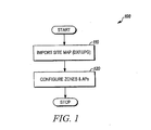
- FIG. 1 is a flow diagram of a method of configuring zones on a site/floor map in accordance with the present invention
- FIG. 2 is a flow diagram of a method of monitoring configured zones for alarm conditions and providing alert notifications to a plurality of wireless devices in accordance with the present invention
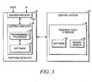
- FIG. 3 is a block diagram of a portable detector and central station for carrying out the methods of FIG. 1 and FIG. 2 in accordance with the present invention
- FIG. 4 is a schematic diagram of a system for carrying out the methods of FIG. 1 and FIG. 2 in accordance with the present invention
- FIG. 5 is an interactive window displayed on a viewing screen of a graphical user interface for displaying a site/floor map in accordance with the present invention
- FIG. 6 is an interactive window displayed on a viewing screen of a graphical user interface for displaying configured zones on a site/floor map in accordance with the present invention
- FIG. 7 is an interactive window displayed on a viewing screen of a graphical user interface for displaying the alarm level of configured zones on a site/floor map in accordance with the present invention
- FIG. 8 is an interactive window displayed on a viewing screen of a graphical user interface for displaying notifications sent to devices in configured zones on a site/floor map in accordance with the present invention.
- FIG. 9 is schematic diagram of a system for sending emergency messages to a plurality of communication devices in accordance with the present invention.
- Embodiments of the present invention include system and methods of monitoring zones for alarm conditions and automatically alerting individuals in a plurality of zones about the safety of a particular zone.
- such systems and methods transmit notification signals to a plurality of portable devices to alert individuals associated with the portable devices that an alarm condition has been detected.
- systems and methods in accordance with the present invention can compute and transmit alarm levels (e.g., emergency, warning, information) associated with the portable devices.
- a user can configure the zone criticality (e.g., critical, non-critical, safe area) for each of the zones in the plurality.
- the zone criticality of each zone can aid a user in graphically differentiating between the plurality of zones, and to prioritize actions when multiple active zones are detected.
- Systems in accordance with the present invention can include a wireless infrastructure, a central station, and a plurality of wireless devices (fixed or portable/mobile).
- the wireless infrastructure in accordance with the present invention can include, for example, a plurality of access points.
- the central station in accordance with the present invention can include control circuitry, a programmable processor, and configuring/monitoring software, stored on local computer readable medium, as would be understood by those of skill in the art.
- the central station can include a server, a personal computer, or a personal computer application, such as a software program.
- the wireless devices in accordance with the present invention can be fixed or portable/mobile and include sensor, control, and/or wireless circuitry and an ambient condition detector and/or a plurality of sensors or detectors.
- a wireless device can include a smoke detector, a heat detector, a gas detector, or any combination thereof.
- the central station can configure a predefined area into multiple zones.
- a zone criticality e.g., critical, non-critical, safe assembly or high, low, medium
- the central station can graphically differentiate the multiple zones based on the assigned criticality of each zone.
- Each wireless device in the area can periodically send ambient condition data and location data to the central station.
- the central station can use data received from the wireless devices to compute the alarm level for each zone. Based on the received data, the central station can determine whether a particular zone is an active zone and graphically represent that zone accordingly. Because location data is periodically sent to the central station, the central station can periodically or dynamically compute the alarm level for each zone.
- Active zones can be zones in which an alarm condition has been detected and are deemed dangerous.
- an active zone can be a zone in which smoke has been detected, an elevated level of heat has been detected, or a gas leak has been detected.
- a zoning algorithm associated with the central station can determine the type of alert to be sent to a wireless device, depending on where that device is located. The central station can then send alert notifications to the plurality of wireless devices in the area. For example, in embodiments of the present invention, the central station can send a pre-alert notification to a wireless device that is near an active zone. The central station can determine if an individual associated with a particular wireless device is headed in the direction of an active zone and send a pre-alert notification to avoid the active zone.
- the central station can also send, for example, information alerts, emergency alerts, or warning alerts to the wireless devices based on the location of the zone with respect to an active zone. For example, an emergency alert can be sent to a wireless device in an active zone, and an information alert can be sent to a wireless device located within a predetermined distance from an active zone.
- the central station can send an alert notification to an emergency response team if, for example, the central station does not receive confirmation that an emergency notification was received by a wireless device in an active zone.
- Systems and methods in accordance with the present invention include a wireless infrastructure with a plurality of access points, a plurality of wireless devices with ambient condition detectors, and a central station.
- the central station can communicate in a bidirectional manner with each of the wireless devices via the access point infrastructure. That is, each of the plurality of wireless devices can communicate with a nearby access point, which can communicate with the central station.
- a wireless device can send ambient condition data and location data to an access point for transmission to the central station.
- the location data can include a received signal strength indication or a GPS-based signal.
- the central station can transmit, via the access point infrastructure, appropriate alert notifications to the plurality of wireless devices.
- FIG. 1 is a flow diagram of an exemplary method 100 of configuring zones on a site map in accordance with the present invention.
- a site map of a particular region can be imported or loaded onto the central station as in 110.
- the central station can configure a plurality of zones and access points on the site map as in 120.
- the central station can define a plurality of zones by area on the site/floor map and assign at least one access point to facilitate bidirectional communication between wireless devices in a particular zone and the central station.
- the central station can also assign an initial criticality of each zone (e.g., critical, non-critical, safe area). For example, the central station can graphically represent each zone based on the criticality of the zones. When an emergency response is required, the criticality of each zone and the corresponding graphical representation thereof can aid an emergency response team in prioritizing actions to be taken.
- an initial criticality of each zone e.g., critical, non-critical, safe area.
- the central station can graphically represent each zone based on the criticality of the zones.
- the criticality of each zone and the corresponding graphical representation thereof can aid an emergency response team in prioritizing actions to be taken.
- FIG. 2 is a flow diagram of an exemplary method 200 of monitoring configured zones for alarm conditions and providing alert notifications to a plurality of wireless devices in accordance with the present invention.
- wireless devices in accordance with the present invention can be detected by an access point of a wireless network as in 210.
- Each of the wireless devices can send ambient condition data and location data to the central station via the associated access point as in 220.
- the central station can use this data to compute an alarm level for each zone and determine whether each zone is an active zone.
- the central station can determine if a particular device is located in an active zone as in 230. If no devices are located in an active zone, then the central station can continue receiving ambient condition and location data as in 220.
- the central station determines that a device is located in an active zone, then the central station can send an emergency notification to the wireless device(s) in the active zone as in 240.
- the central station can use a zoning algorithm to determine the position of other wireless devices in the area relative to the active zone as in 250. Based on a device's position relative to the active zone, the central station can send appropriate alert notifications to other wireless devices in the plurality.
- a zoning algorithm performed by the central station can determine the type of alert notification to be sent to a particular device. If a particular wireless device is located near an active zone, an emergency notification can be sent to that device. However, if a particular wireless device is located at a predetermined distance away from an active zone, an information notification can be sent to that device.
- the zoning algorithm performed by the central station can also determine whether any wireless devices are approaching an active zone. If a particular wireless device is approaching or entering an active zone, the central station can send a pre-alarm notification to that device to avoid entering into the active zone.
- the alert notifications sent from the central station to a particular wireless device(s) can include the criticality assigned to the zone in which that device is located. Accordingly, an individual associated with a wireless device can be notified about the status of his or her environment. Furthermore, the criticality of a zone can allow the central station to prioritize actions when multiple active zones are detected.
- an individual associated with that device can take appropriate action based on the received notification as in 260.
- a portable detector 11 can include sensing circuitry 13 and control circuitry 10, which can include a programmable processor 12 and software 14, stored on a local computer readable medium, as would be understood by those of ordinary skill in the art. Data received by the portable detector 11 can be input into the sensing circuitry 13 and control circuitry 10.
- the central station 17 can be in communication with the portable detector 11 and include a graphical user interface 16.
- the user interface 16 can include configuring/monitoring software 19 and a viewing screen 18, as would be known by those of skill in the art, for displaying interactive and viewing windows.
- the user interface 16 can be a multi-dimensional graphical user interface.
- FIG. 4 is a schematic diagram of a system 20 for carrying out the methods of FIG. 1 and FIG. 2 in accordance with the present invention.
- the system 20 can include a central station 22, a wireless network with a plurality of access points 24, 25, and a plurality of wireless devices 26, 27, 28, 29, 30.
- the plurality of wireless devices can include fixed ambient condition detectors 26, 27 and/or portable ambient condition detectors 28, 29, 30 that can be carried by or worn on an individual.
- the central station 22 can include a server and/or a personal computer.
- an access point 24 or 25 can include a router or modem.
- each wireless device 26, 27, 28, 29, 30 can communicate with a nearby access point 24, 25 and send ambient condition data and location data thereto.
- the location data can include an indication of received signal strength or a GPS-based signal.
- the central station 22 can communicate in a bidirectional manner with each of the wireless devices 26, 27, 28, 29, 30 via an access point 24 or 25.
- FIG. 5 is an interactive window displayed on a viewing screen 40 of a graphical user interface for displaying a site map in accordance with the present invention.
- the viewing screen 40 can include a window 42 to display a site map that is imported to or loaded onto a central station.
- the site map When initially imported to or loaded onto the central station, the site map does not include zoning information. Instead, in embodiments of the present invention, the site map can be a picture or graphical representation or a CAD diagram of a particular region.
- FIG. 6 is an interactive window displayed on a viewing screen 50 of a graphical user interface for displaying configured zones on a site map in accordance with the present invention.
- the viewing screen 50 can include a window 52 to display a site map with zone configurations therein.
- the window 52 displays the following configured zones: tower 1, tower 2, building 1, unit 1, and safe assembly area.
- the viewing screen 50 can also include a window 54 listing the various configured zones on the site map.
- the central station or a user can assign a criticality to each of the configured zones.
- FIG. 7 is an interactive window displayed on a viewing screen 60 of a graphical user interface for displaying the alarm level of configured zones on a site map in accordance with the present invention.
- the alarm level for each configured zone can be based on ambient condition data received from wireless devices in that zone.
- the alarm level of unit 1 is good condition or no alarm
- the alarm level of tower 1 is low alarm
- the alarm level of building 1 is active zone.
- an active zone can be a zone in which an alarm condition has been detected. That is, an active zone can be a zone in which smoke has been detected, an elevated level of heat has been detected, or a gas leak has been detected.
- FIG. 8 is an interactive window displayed on a viewing screen 70 of a graphical user interface for displaying the notifications sent to devices in configured zones on a site map in accordance with the present invention.
- the central station can send an alert notification to wireless devices in a particular zone based on the alarm levels determined for the plurality of zones.
- wireless devices in the unit 1 and tower 1 zones can receive information alerts. However, since the tower 2 zone is closer to the active zone, wireless devices in the tower 2 zone can receive a warning alert. Wireless devices in the active zone can receive an emergency alert.
- Systems and methods in accordance with the present invention can determine when a wireless device is moving based on received location data over a period of time. When a particular wireless device is near or moving towards an active zone, that wireless device can receive a pre-alarm notification, as seen in FIG. 8 .
- the wireless device can transmit confirmation, via the access point infrastructure, to the central station that the alert notification was received. If the central station does not receive confirmation from a wireless device within a predetermined period of time, the central station can send an emergency notification to an emergency response team (ERT) or others about an alarm condition in an active region.
- ERT emergency response team
- FIG. 9 is schematic diagram of a system for sending emergency messages to a plurality of individuals in accordance with the present invention.
- the system 80 can include a central station 82, a wireless network with at least one access point 84, and a plurality of communication devices 85, 86, 87.
- the central station 82 can include a server or a personal computer, and the at least one access point 84 can include a router or a modem.
- the plurality of communication devices can include a personal computer, or a cellular phone.
- the central station can send an emergency notification to a plurality of communication devices in an appropriate format for being received by a particular communication device.
- the emergency notification can be an email.
- the emergency notification can be a voicemail or a text message.
Landscapes
- Business, Economics & Management (AREA)
- Emergency Management (AREA)
- Physics & Mathematics (AREA)
- General Physics & Mathematics (AREA)
- Engineering & Computer Science (AREA)
- Computer Security & Cryptography (AREA)
- Alarm Systems (AREA)
- Mobile Radio Communication Systems (AREA)
- Telephonic Communication Services (AREA)
- Emergency Alarm Devices (AREA)
Claims (9)
- Procédé d'alerte et de surveillance de zones, comprenant les étapes consistant à :doter (110) une station centrale (17) d'un plan d'emplacement/au sol d'un secteur prédéfini ;configurer (120), dans la station centrale, le secteur prédéfini en une pluralité de zones ;affecter, dans la station centrale, un paramètre de criticité à chaque zone parmi la pluralité de zones ;doter le secteur prédéfini d'une pluralité de dispositifs sans fil ;affecter au moins un point d'accès (24, 25, 84) au sein de chaque zone parmi la pluralité de zones, ledit au moins un point d'accès (24, 25, 84) étant configuré pour permettre les communications bidirectionnelles entre la station centrale (22, 82) et la pluralité de dispositifs sans fil ;recevoir, au niveau de la station centrale, par l'intermédiaire dudit au moins un point d'accès (24, 25, 84) de chaque zone, des données de conditions ambiantes et des données de position en provenance de la pluralité de dispositifs sans fil (23-30, 85-87) ;calculer, dans la station centrale, un niveau d'alarme pour chaque zone parmi la pluralité de zones à partir des données de conditions ambiantes et des données de position reçues des dispositifs sans fil ;établir, dans la station centrale, des notifications d'alerte et transmettre ces dernières de la station centrale à la pluralité de dispositifs sans fil (23-30, 85-87) ;établir, dans la station centrale, si un quelconque dispositif sans fil s'approche d'une zone active, une zone active étant une zone dans laquelle une condition d'alarme a été détectée et qui est jugée dangereuse, et envoyer une notification de préalarme à ce dispositif pour empêcher l'accès à cette zone active ;laquelle notification d'alerte envoyée à chaque dispositif sans fil est basée sur le niveau d'alarme calculé de la zone dans laquelle ce dispositif sans fil est positionné et comprend le paramètre de criticité affecté à la zone dans laquelle le dispositif est positionné ; etclasser des actions par ordre de priorité, au niveau de la station centrale, en fonction de la criticité de zones en cas de détection de plusieurs zones actives.
- Procédé selon la revendication 1, l'étape consistant à transmettre des notifications d'alerte comportant l'étape consistant à transmettre une alerte d'urgence à des zones actives, à transmettre une alerte de mise en garde à des zones éloignées d'une distance prédéfinie de zones actives, et à transmettre une alerte de mise en garde à des zones au-delà de la distance prédéfinie des zones actives.
- Procédé selon la revendication 1, l'étape consistant à doter la station centrale d'un plan d'emplacement/au sol d'un secteur prédéfini comportant l'étape consistant à importer ou à charger le plan d'emplacement dans la station centrale (22, 82).
- Procédé selon la revendication 1, comprenant en outre l'étape consistant à transmettre, par chacun parmi la pluralité de dispositifs sans fil, une notification de confirmation dès réception d'une notification d'alerte.
- Procédé selon la revendication 1, certains au moins des dispositifs sans fil étant fixes ou portables ou mobiles.
- Station centrale (22, 82), comprenant :un montage de circuits servant à doter une station centrale (17) d'un plan d'emplacement/au sol d'un secteur prédéfini ;un montage de circuits servant à configurer le secteur prédéfini en une pluralité de zones, et à affecter un paramètre de criticité à chaque zone parmi la pluralité de zones ;un montage de circuits servant à affecter au moins un point d'accès (24, 25, 84) au sein de chaque zone parmi la pluralité de zones ;un montage de circuits servant à communiquer avec une pluralité de points d'accès en communication avec une pluralité de dispositifs sans fil ;un montage de circuits servant à recevoir, par l'intermédiaire dudit au moins un point d'accès (24, 25, 84) de chaque zone, des données de conditions ambiantes et des données de position en provenance de la pluralité de dispositifs sans fil (23-30, 85-87) positionnés dans le secteur prédéfini ;un montage de circuits servant à calculer un niveau d'alarme pour chaque zone parmi la pluralité de zones à partir des données de conditions ambiantes et des données de position reçues des dispositifs sans fil ; etun montage de circuits servant à établir des notifications d'alerte et à transmettre ces dernières de la station centrale à la pluralité de dispositifs sans fil ;un montage de circuits servant à établir si un quelconque dispositif sans fil s'approche d'une zone active, une zone active étant une zone dans laquelle une condition d'alarme a été détectée et qui est jugée dangereuse, et à envoyer une notification de préalarme à ce dispositif pour empêcher l'accès à cette zone active ;laquelle notification d'alerte envoyée à chaque dispositif sans fil est basée sur le niveau d'alarme calculé de la zone dans laquelle ce dispositif sans fil est positionné et comprend le paramètre de criticité affecté à la zone dans laquelle le dispositif est positionné ; etun montage de circuits servant à classer des actions par ordre de priorité en fonction de la criticité de zones en cas de détection de plusieurs zones actives.
- Station centrale selon la revendication 6, le montage de circuits servant à transmettre des notifications d'alerte étant apte à transmettre une alerte d'urgence à des zones actives, à transmettre une alerte de mise en garde à des zones éloignées d'une distance prédéfinie de zones actives, et à transmettre une alerte de mise en garde à des zones au-delà de la distance prédéfinie des zones actives.
- Station centrale selon la revendication 6, comportant un serveur ou un ordinateur personnel.
- Station centrale (22, 82) selon la revendication 6, comportant un écran de visualisation interactif (40, 50, 60, 70) et un logiciel enregistré sur un support exploitable par ordinateur local.
Applications Claiming Priority (1)
| Application Number | Priority Date | Filing Date | Title |
|---|---|---|---|
| US12/621,713 US9792808B2 (en) | 2009-11-19 | 2009-11-19 | Alert system with zoning using wireless portable detectors and a central station |
Publications (2)
| Publication Number | Publication Date |
|---|---|
| EP2325822A1 EP2325822A1 (fr) | 2011-05-25 |
| EP2325822B1 true EP2325822B1 (fr) | 2012-07-25 |
Family
ID=43384660
Family Applications (1)
| Application Number | Title | Priority Date | Filing Date |
|---|---|---|---|
| EP10191385A Active EP2325822B1 (fr) | 2009-11-19 | 2010-11-16 | Système d'alerte avec zonage utilisant des détecteurs portables sans fil et une station centrale |
Country Status (9)
| Country | Link |
|---|---|
| US (1) | US9792808B2 (fr) |
| EP (1) | EP2325822B1 (fr) |
| CN (1) | CN102074101B (fr) |
| AU (1) | AU2010241417B2 (fr) |
| BR (1) | BRPI1004847A2 (fr) |
| CA (1) | CA2721027C (fr) |
| ES (1) | ES2390608T3 (fr) |
| SG (1) | SG171550A1 (fr) |
| TW (1) | TWI524310B (fr) |
Cited By (1)
| Publication number | Priority date | Publication date | Assignee | Title |
|---|---|---|---|---|
| US9792808B2 (en) | 2009-11-19 | 2017-10-17 | Honeywell International Inc. | Alert system with zoning using wireless portable detectors and a central station |
Families Citing this family (36)
| Publication number | Priority date | Publication date | Assignee | Title |
|---|---|---|---|---|
| WO2011163604A1 (fr) | 2010-06-25 | 2011-12-29 | Industrial Scientific Corporation | Dispositif et procédé de surveillance environnementale à détections multiples |
| US8818713B2 (en) | 2011-07-20 | 2014-08-26 | Honeywell International Inc. | System and apparatus providing localized evacuation guidance |
| US8769023B2 (en) | 2011-08-03 | 2014-07-01 | Juniper Networks, Inc. | Disaster response system |
| JP2013054494A (ja) * | 2011-09-02 | 2013-03-21 | Sony Corp | 情報処理装置、情報処理方法、プログラム、記録媒体、及び情報処理システム |
| EP2631887A1 (fr) * | 2012-02-22 | 2013-08-28 | mecom Medien-Communikations-Gesellschaft mbH | Système d'alerte et procédé de fonctionnement d'un système d'alerte |
| US20130249671A1 (en) * | 2012-03-16 | 2013-09-26 | Mecom Medien-Communikations-Gesellschaft Mbh | Warning System and Method for Operating a Warning System |
| WO2013163515A1 (fr) * | 2012-04-27 | 2013-10-31 | Mejia Leonardo | Système d'alarme |
| GB201301576D0 (en) * | 2013-01-29 | 2013-03-13 | Georeach | System |
| WO2013186519A2 (fr) * | 2012-06-11 | 2013-12-19 | Georeach Limited | Système de surveillance, serveur, dispositif mobile, et procédé |
| CN102914780A (zh) * | 2012-10-23 | 2013-02-06 | 东北林业大学 | 基于gprs网络的野外实习用学生位置监测方法与装置 |
| US9000913B2 (en) * | 2013-01-02 | 2015-04-07 | Honeywell International Inc. | Wearable low pressure warning device with audio and visual indication |
| US20140210639A1 (en) * | 2013-01-29 | 2014-07-31 | James Skourlis | Central alarm (ca) unit in a gas monitoring system including gas sensors and gas sensor controllers |
| US10433143B2 (en) * | 2013-09-03 | 2019-10-01 | Guard911 LLC | Systems and methods for notifying law enforcement officers of armed intruder situations# |
| CN104468166B (zh) * | 2013-09-18 | 2019-07-19 | 中兴通讯股份有限公司 | 一种告警处理优先级确定方法及系统 |
| US9262903B2 (en) * | 2013-10-11 | 2016-02-16 | Honeywell International Inc. | System and method to monitor events and personnel locations |
| FR3020704B1 (fr) * | 2014-05-02 | 2016-05-27 | Airbus | Prevention de risques lors d'une intervention sur un aeronef |
| US9013297B1 (en) * | 2014-10-17 | 2015-04-21 | Ockham Razor Ventures, LLC | Condition responsive indication assembly and method |
| US10383384B2 (en) | 2014-10-17 | 2019-08-20 | Guardhat, Inc. | Electrical connection for suspension band attachment slot of a hard hat |
| US9486027B2 (en) | 2014-10-17 | 2016-11-08 | Guardhat, Inc. | Connection assembly for adjoining a peripheral with a host wearable device |
| US10667571B2 (en) * | 2014-10-17 | 2020-06-02 | Guardhat, Inc. | Condition responsive indication assembly and method |
| US9642574B2 (en) | 2014-10-17 | 2017-05-09 | Guardhat, Inc. | Biometric sensors assembly for a hard hat |
| KR101671209B1 (ko) * | 2016-03-17 | 2016-11-01 | 주식회사 지에스아이엘 | 터널 공사현장의 작업자 안전관리 시스템 |
| US10533965B2 (en) | 2016-04-19 | 2020-01-14 | Industrial Scientific Corporation | Combustible gas sensing element with cantilever support |
| CN109565516B (zh) | 2016-04-19 | 2024-08-23 | 工业科技有限公司 | 工作人员安全系统 |
| AU2016412194B2 (en) * | 2016-06-13 | 2019-11-21 | Infotronic Technology Limited | Location based quality assurance system |
| US9980112B1 (en) * | 2016-11-23 | 2018-05-22 | Salesforce.Com, Inc. | System and method for coordinating an emergency response at a facility |
| US10027792B1 (en) | 2017-06-12 | 2018-07-17 | Robert J. Sweeney | Systems and methods for notifying users of emergency impact zones |
| CN108010282B (zh) * | 2017-11-30 | 2020-12-04 | 中冶南方工程技术有限公司 | 有毒气体分布时图的绘制方法及有毒气体场所的救助方法 |
| US10887747B2 (en) | 2018-04-20 | 2021-01-05 | Whelen Engineering Company, Inc. | Systems and methods for remote management of emergency equipment and personnel |
| US10657821B2 (en) | 2018-06-13 | 2020-05-19 | Whelen Engineering Company, Inc. | Autonomous intersection warning system for connected vehicles |
| US10573147B1 (en) * | 2018-09-04 | 2020-02-25 | Abb Schweiz Ag | Technologies for managing safety at industrial sites |
| US12177734B2 (en) | 2019-01-09 | 2024-12-24 | Whelen Engineering Company, Inc. | System and method for velocity-based geofencing for emergency vehicle |
| US10706722B1 (en) | 2019-03-06 | 2020-07-07 | Whelen Engineering Company, Inc. | System and method for map-based geofencing for emergency vehicle |
| US10531224B1 (en) | 2019-03-11 | 2020-01-07 | Whelen Engineering Company, Inc. | System and method for managing emergency vehicle alert geofence |
| US11246187B2 (en) | 2019-05-30 | 2022-02-08 | Industrial Scientific Corporation | Worker safety system with scan mode |
| US11758354B2 (en) * | 2019-10-15 | 2023-09-12 | Whelen Engineering Company, Inc. | System and method for intent-based geofencing for emergency vehicle |
Citations (1)
| Publication number | Priority date | Publication date | Assignee | Title |
|---|---|---|---|---|
| NO20075550L (no) * | 2007-11-02 | 2009-05-04 | Lars Tidemann Dahl | Anordning og system for identifisering, adgang, lokalisering og orientering i bygninger, skip og andre konstruksjoner |
Family Cites Families (16)
| Publication number | Priority date | Publication date | Assignee | Title |
|---|---|---|---|---|
| US5400246A (en) * | 1989-05-09 | 1995-03-21 | Ansan Industries, Ltd. | Peripheral data acquisition, monitor, and adaptive control system via personal computer |
| JPH081459B2 (ja) | 1991-12-07 | 1996-01-10 | 進 佐久間 | 電波による非常信号を利用した警備方法 |
| US5959529A (en) * | 1997-03-07 | 1999-09-28 | Kail, Iv; Karl A. | Reprogrammable remote sensor monitoring system |
| US6084510A (en) * | 1997-04-18 | 2000-07-04 | Lemelson; Jerome H. | Danger warning and emergency response system and method |
| CA2215440C (fr) | 1997-09-15 | 2003-12-16 | Thom Kennedy | Systeme de surveillance et de signalisation d'alarmes |
| US6031455A (en) * | 1998-02-09 | 2000-02-29 | Motorola, Inc. | Method and apparatus for monitoring environmental conditions in a communication system |
| WO2000021053A1 (fr) * | 1998-10-06 | 2000-04-13 | Slc Technologies, Inc. | Systeme prive d'alarme de securite et d'incendie |
| US6028514A (en) | 1998-10-30 | 2000-02-22 | Lemelson Jerome H. | Personal emergency, safety warning system and method |
| US20030137415A1 (en) | 2002-01-22 | 2003-07-24 | Thomson James D. | Homeland security emergency notification system |
| US20030227381A1 (en) | 2002-03-07 | 2003-12-11 | Best Hilary A. | Alarm notification device |
| US7277018B2 (en) | 2004-09-17 | 2007-10-02 | Incident Alert Systems, Llc | Computer-enabled, networked, facility emergency notification, management and alarm system |
| CN2800403Y (zh) | 2004-10-08 | 2006-07-26 | 曹晓克 | 便携式防空报警远程无线区域集中指挥中心 |
| US7283045B1 (en) | 2006-01-26 | 2007-10-16 | The United States Of America As Represented By The Secretary Of The Army | System and method for semi-distributed event warning notification for individual entities, and computer program product therefor |
| US20080088434A1 (en) | 2006-10-17 | 2008-04-17 | Russell Frieder | Rapid disaster notification system |
| TW200741595A (en) | 2007-04-24 | 2007-11-01 | Univ Chang Gung | Personal safety care monitoring system and method |
| US9792808B2 (en) | 2009-11-19 | 2017-10-17 | Honeywell International Inc. | Alert system with zoning using wireless portable detectors and a central station |
-
2009
- 2009-11-19 US US12/621,713 patent/US9792808B2/en active Active
-
2010
- 2010-11-12 AU AU2010241417A patent/AU2010241417B2/en active Active
- 2010-11-15 CA CA2721027A patent/CA2721027C/fr active Active
- 2010-11-16 EP EP10191385A patent/EP2325822B1/fr active Active
- 2010-11-16 ES ES10191385T patent/ES2390608T3/es active Active
- 2010-11-18 CN CN201010610831.2A patent/CN102074101B/zh active Active
- 2010-11-18 TW TW099139770A patent/TWI524310B/zh active
- 2010-11-18 SG SG201008457-2A patent/SG171550A1/en unknown
- 2010-11-19 BR BRPI1004847-2A patent/BRPI1004847A2/pt not_active Application Discontinuation
Patent Citations (1)
| Publication number | Priority date | Publication date | Assignee | Title |
|---|---|---|---|---|
| NO20075550L (no) * | 2007-11-02 | 2009-05-04 | Lars Tidemann Dahl | Anordning og system for identifisering, adgang, lokalisering og orientering i bygninger, skip og andre konstruksjoner |
Cited By (1)
| Publication number | Priority date | Publication date | Assignee | Title |
|---|---|---|---|---|
| US9792808B2 (en) | 2009-11-19 | 2017-10-17 | Honeywell International Inc. | Alert system with zoning using wireless portable detectors and a central station |
Also Published As
| Publication number | Publication date |
|---|---|
| TW201140514A (en) | 2011-11-16 |
| CN102074101A (zh) | 2011-05-25 |
| CA2721027C (fr) | 2017-11-28 |
| EP2325822A1 (fr) | 2011-05-25 |
| CA2721027A1 (fr) | 2011-05-19 |
| US20110115623A1 (en) | 2011-05-19 |
| CN102074101B (zh) | 2014-11-26 |
| SG171550A1 (en) | 2011-06-29 |
| AU2010241417B2 (en) | 2015-07-02 |
| TWI524310B (zh) | 2016-03-01 |
| AU2010241417A1 (en) | 2011-06-02 |
| US9792808B2 (en) | 2017-10-17 |
| BRPI1004847A2 (pt) | 2013-03-12 |
| ES2390608T3 (es) | 2012-11-14 |
Similar Documents
| Publication | Publication Date | Title |
|---|---|---|
| EP2325822B1 (fr) | Système d'alerte avec zonage utilisant des détecteurs portables sans fil et une station centrale | |
| US11842620B2 (en) | Systems and methods for robust man-down alarms | |
| US10540622B2 (en) | Fluid container resource management | |
| CN102870144B (zh) | 采用网络服务器和电子邮件通知的抽吸环境传感器 | |
| EP3295442B1 (fr) | Procédé pour auto-configurer des détecteurs de gaz sur la base d'un emplacement en temps réel | |
| CN107438766B (zh) | 基于图像的监视系统 | |
| US20140333432A1 (en) | Systems and methods for worker location and safety confirmation | |
| EP2905760A2 (fr) | Système et procédé de comptabilité de dénombrement des effectifs étiquetés de localisation | |
| EP3405936B1 (fr) | Détecteur de gaz permettant de détecter des gaz multiples | |
| EP1965362A2 (fr) | Réseau à rapport et avertissement d'intrusion | |
| JP6505168B2 (ja) | 通報システム | |
| JP2017131256A (ja) | デジタルサイネージシステム | |
| JP2017142649A (ja) | 警備業務支援システムおよび警備装置 | |
| KR20140057443A (ko) | 선박의 화재 경보 시스템 및 이를 이용한 화재 경보 감시 방법 | |
| JP6514488B2 (ja) | ウェアラブル端末 | |
| KR20190053388A (ko) | 매트를 이용한 안전감지 시스템 | |
| US11176799B2 (en) | Global positioning system equipped with hazard detector and a system for providing hazard alerts thereby | |
| JP6603546B2 (ja) | 防災支援システム | |
| EP4162457B1 (fr) | Dispositif de détection personnel destiné à être porté par une personne sur un site, ainsi que l'utilisation d'un tel dispositif de détection personnel et système comprenant un ou plusieurs desdits dispositifs de détection personnels | |
| WO2018094455A1 (fr) | Dispositif, système et procédé de communication | |
| JP6435137B2 (ja) | 被管理者監視システム、被管理者監視方法、プログラム、及び記録媒体 | |
| KR20230073711A (ko) | 안전경로 안내 서버 및 이를 이용한 안전경로 안내 방법 | |
| KR20230127673A (ko) | 작업장에서의 재난경보 제공방법 | |
| JP2009175919A (ja) | 無線通報システム |
Legal Events
| Date | Code | Title | Description |
|---|---|---|---|
| PUAI | Public reference made under article 153(3) epc to a published international application that has entered the european phase |
Free format text: ORIGINAL CODE: 0009012 |
|
| 17P | Request for examination filed |
Effective date: 20101116 |
|
| AK | Designated contracting states |
Kind code of ref document: A1 Designated state(s): AL AT BE BG CH CY CZ DE DK EE ES FI FR GB GR HR HU IE IS IT LI LT LU LV MC MK MT NL NO PL PT RO RS SE SI SK SM TR |
|
| AX | Request for extension of the european patent |
Extension state: BA ME |
|
| TPAC | Observations filed by third parties |
Free format text: ORIGINAL CODE: EPIDOSNTIPA |
|
| GRAP | Despatch of communication of intention to grant a patent |
Free format text: ORIGINAL CODE: EPIDOSNIGR1 |
|
| GRAS | Grant fee paid |
Free format text: ORIGINAL CODE: EPIDOSNIGR3 |
|
| GRAA | (expected) grant |
Free format text: ORIGINAL CODE: 0009210 |
|
| AK | Designated contracting states |
Kind code of ref document: B1 Designated state(s): AL AT BE BG CH CY CZ DE DK EE ES FI FR GB GR HR HU IE IS IT LI LT LU LV MC MK MT NL NO PL PT RO RS SE SI SK SM TR |
|
| REG | Reference to a national code |
Ref country code: GB Ref legal event code: FG4D |
|
| REG | Reference to a national code |
Ref country code: CH Ref legal event code: EP |
|
| REG | Reference to a national code |
Ref country code: AT Ref legal event code: REF Ref document number: 567974 Country of ref document: AT Kind code of ref document: T Effective date: 20120815 Ref country code: IE Ref legal event code: FG4D |
|
| REG | Reference to a national code |
Ref country code: DE Ref legal event code: R096 Ref document number: 602010002292 Country of ref document: DE Effective date: 20120920 |
|
| REG | Reference to a national code |
Ref country code: ES Ref legal event code: FG2A Ref document number: 2390608 Country of ref document: ES Kind code of ref document: T3 Effective date: 20121114 |
|
| REG | Reference to a national code |
Ref country code: NL Ref legal event code: VDEP Effective date: 20120725 |
|
| REG | Reference to a national code |
Ref country code: AT Ref legal event code: MK05 Ref document number: 567974 Country of ref document: AT Kind code of ref document: T Effective date: 20120725 |
|
| REG | Reference to a national code |
Ref country code: LT Ref legal event code: MG4D Effective date: 20120725 |
|
| PG25 | Lapsed in a contracting state [announced via postgrant information from national office to epo] |
Ref country code: AT Free format text: LAPSE BECAUSE OF FAILURE TO SUBMIT A TRANSLATION OF THE DESCRIPTION OR TO PAY THE FEE WITHIN THE PRESCRIBED TIME-LIMIT Effective date: 20120725 Ref country code: NO Free format text: LAPSE BECAUSE OF FAILURE TO SUBMIT A TRANSLATION OF THE DESCRIPTION OR TO PAY THE FEE WITHIN THE PRESCRIBED TIME-LIMIT Effective date: 20121025 Ref country code: CY Free format text: LAPSE BECAUSE OF FAILURE TO SUBMIT A TRANSLATION OF THE DESCRIPTION OR TO PAY THE FEE WITHIN THE PRESCRIBED TIME-LIMIT Effective date: 20120725 Ref country code: BE Free format text: LAPSE BECAUSE OF FAILURE TO SUBMIT A TRANSLATION OF THE DESCRIPTION OR TO PAY THE FEE WITHIN THE PRESCRIBED TIME-LIMIT Effective date: 20120725 Ref country code: HR Free format text: LAPSE BECAUSE OF FAILURE TO SUBMIT A TRANSLATION OF THE DESCRIPTION OR TO PAY THE FEE WITHIN THE PRESCRIBED TIME-LIMIT Effective date: 20120725 Ref country code: FI Free format text: LAPSE BECAUSE OF FAILURE TO SUBMIT A TRANSLATION OF THE DESCRIPTION OR TO PAY THE FEE WITHIN THE PRESCRIBED TIME-LIMIT Effective date: 20120725 Ref country code: IS Free format text: LAPSE BECAUSE OF FAILURE TO SUBMIT A TRANSLATION OF THE DESCRIPTION OR TO PAY THE FEE WITHIN THE PRESCRIBED TIME-LIMIT Effective date: 20121125 Ref country code: LT Free format text: LAPSE BECAUSE OF FAILURE TO SUBMIT A TRANSLATION OF THE DESCRIPTION OR TO PAY THE FEE WITHIN THE PRESCRIBED TIME-LIMIT Effective date: 20120725 |
|
| PG25 | Lapsed in a contracting state [announced via postgrant information from national office to epo] |
Ref country code: GR Free format text: LAPSE BECAUSE OF FAILURE TO SUBMIT A TRANSLATION OF THE DESCRIPTION OR TO PAY THE FEE WITHIN THE PRESCRIBED TIME-LIMIT Effective date: 20121026 Ref country code: SE Free format text: LAPSE BECAUSE OF FAILURE TO SUBMIT A TRANSLATION OF THE DESCRIPTION OR TO PAY THE FEE WITHIN THE PRESCRIBED TIME-LIMIT Effective date: 20120725 Ref country code: PL Free format text: LAPSE BECAUSE OF FAILURE TO SUBMIT A TRANSLATION OF THE DESCRIPTION OR TO PAY THE FEE WITHIN THE PRESCRIBED TIME-LIMIT Effective date: 20120725 Ref country code: LV Free format text: LAPSE BECAUSE OF FAILURE TO SUBMIT A TRANSLATION OF THE DESCRIPTION OR TO PAY THE FEE WITHIN THE PRESCRIBED TIME-LIMIT Effective date: 20120725 Ref country code: PT Free format text: LAPSE BECAUSE OF FAILURE TO SUBMIT A TRANSLATION OF THE DESCRIPTION OR TO PAY THE FEE WITHIN THE PRESCRIBED TIME-LIMIT Effective date: 20121126 Ref country code: SI Free format text: LAPSE BECAUSE OF FAILURE TO SUBMIT A TRANSLATION OF THE DESCRIPTION OR TO PAY THE FEE WITHIN THE PRESCRIBED TIME-LIMIT Effective date: 20120725 |
|
| PG25 | Lapsed in a contracting state [announced via postgrant information from national office to epo] |
Ref country code: NL Free format text: LAPSE BECAUSE OF FAILURE TO SUBMIT A TRANSLATION OF THE DESCRIPTION OR TO PAY THE FEE WITHIN THE PRESCRIBED TIME-LIMIT Effective date: 20120725 |
|
| PG25 | Lapsed in a contracting state [announced via postgrant information from national office to epo] |
Ref country code: RO Free format text: LAPSE BECAUSE OF FAILURE TO SUBMIT A TRANSLATION OF THE DESCRIPTION OR TO PAY THE FEE WITHIN THE PRESCRIBED TIME-LIMIT Effective date: 20120725 Ref country code: EE Free format text: LAPSE BECAUSE OF FAILURE TO SUBMIT A TRANSLATION OF THE DESCRIPTION OR TO PAY THE FEE WITHIN THE PRESCRIBED TIME-LIMIT Effective date: 20120725 Ref country code: DK Free format text: LAPSE BECAUSE OF FAILURE TO SUBMIT A TRANSLATION OF THE DESCRIPTION OR TO PAY THE FEE WITHIN THE PRESCRIBED TIME-LIMIT Effective date: 20120725 Ref country code: CZ Free format text: LAPSE BECAUSE OF FAILURE TO SUBMIT A TRANSLATION OF THE DESCRIPTION OR TO PAY THE FEE WITHIN THE PRESCRIBED TIME-LIMIT Effective date: 20120725 |
|
| PG25 | Lapsed in a contracting state [announced via postgrant information from national office to epo] |
Ref country code: SK Free format text: LAPSE BECAUSE OF FAILURE TO SUBMIT A TRANSLATION OF THE DESCRIPTION OR TO PAY THE FEE WITHIN THE PRESCRIBED TIME-LIMIT Effective date: 20120725 |
|
| PLBE | No opposition filed within time limit |
Free format text: ORIGINAL CODE: 0009261 |
|
| STAA | Information on the status of an ep patent application or granted ep patent |
Free format text: STATUS: NO OPPOSITION FILED WITHIN TIME LIMIT |
|
| 26N | No opposition filed |
Effective date: 20130426 |
|
| PG25 | Lapsed in a contracting state [announced via postgrant information from national office to epo] |
Ref country code: BG Free format text: LAPSE BECAUSE OF FAILURE TO SUBMIT A TRANSLATION OF THE DESCRIPTION OR TO PAY THE FEE WITHIN THE PRESCRIBED TIME-LIMIT Effective date: 20121025 Ref country code: RS Free format text: LAPSE BECAUSE OF FAILURE TO SUBMIT A TRANSLATION OF THE DESCRIPTION OR TO PAY THE FEE WITHIN THE PRESCRIBED TIME-LIMIT Effective date: 20120725 |
|
| REG | Reference to a national code |
Ref country code: IE Ref legal event code: MM4A |
|
| REG | Reference to a national code |
Ref country code: DE Ref legal event code: R097 Ref document number: 602010002292 Country of ref document: DE Effective date: 20130426 |
|
| PG25 | Lapsed in a contracting state [announced via postgrant information from national office to epo] |
Ref country code: IE Free format text: LAPSE BECAUSE OF NON-PAYMENT OF DUE FEES Effective date: 20121116 |
|
| PG25 | Lapsed in a contracting state [announced via postgrant information from national office to epo] |
Ref country code: AL Free format text: LAPSE BECAUSE OF FAILURE TO SUBMIT A TRANSLATION OF THE DESCRIPTION OR TO PAY THE FEE WITHIN THE PRESCRIBED TIME-LIMIT Effective date: 20120725 Ref country code: MT Free format text: LAPSE BECAUSE OF FAILURE TO SUBMIT A TRANSLATION OF THE DESCRIPTION OR TO PAY THE FEE WITHIN THE PRESCRIBED TIME-LIMIT Effective date: 20120725 |
|
| REG | Reference to a national code |
Ref country code: ES Ref legal event code: FD2A Effective date: 20140304 |
|
| PG25 | Lapsed in a contracting state [announced via postgrant information from national office to epo] |
Ref country code: TR Free format text: LAPSE BECAUSE OF FAILURE TO SUBMIT A TRANSLATION OF THE DESCRIPTION OR TO PAY THE FEE WITHIN THE PRESCRIBED TIME-LIMIT Effective date: 20120725 Ref country code: MC Free format text: LAPSE BECAUSE OF NON-PAYMENT OF DUE FEES Effective date: 20121130 |
|
| PG25 | Lapsed in a contracting state [announced via postgrant information from national office to epo] |
Ref country code: ES Free format text: LAPSE BECAUSE OF NON-PAYMENT OF DUE FEES Effective date: 20121117 Ref country code: LU Free format text: LAPSE BECAUSE OF NON-PAYMENT OF DUE FEES Effective date: 20121116 Ref country code: SM Free format text: LAPSE BECAUSE OF FAILURE TO SUBMIT A TRANSLATION OF THE DESCRIPTION OR TO PAY THE FEE WITHIN THE PRESCRIBED TIME-LIMIT Effective date: 20120725 |
|
| PG25 | Lapsed in a contracting state [announced via postgrant information from national office to epo] |
Ref country code: HU Free format text: LAPSE BECAUSE OF FAILURE TO SUBMIT A TRANSLATION OF THE DESCRIPTION OR TO PAY THE FEE WITHIN THE PRESCRIBED TIME-LIMIT Effective date: 20101116 |
|
| REG | Reference to a national code |
Ref country code: CH Ref legal event code: PL |
|
| PG25 | Lapsed in a contracting state [announced via postgrant information from national office to epo] |
Ref country code: MK Free format text: LAPSE BECAUSE OF FAILURE TO SUBMIT A TRANSLATION OF THE DESCRIPTION OR TO PAY THE FEE WITHIN THE PRESCRIBED TIME-LIMIT Effective date: 20120725 Ref country code: CH Free format text: LAPSE BECAUSE OF NON-PAYMENT OF DUE FEES Effective date: 20141130 Ref country code: LI Free format text: LAPSE BECAUSE OF NON-PAYMENT OF DUE FEES Effective date: 20141130 |
|
| REG | Reference to a national code |
Ref country code: FR Ref legal event code: PLFP Year of fee payment: 6 |
|
| REG | Reference to a national code |
Ref country code: FR Ref legal event code: PLFP Year of fee payment: 7 |
|
| REG | Reference to a national code |
Ref country code: FR Ref legal event code: PLFP Year of fee payment: 8 |
|
| PGFP | Annual fee paid to national office [announced via postgrant information from national office to epo] |
Ref country code: DE Payment date: 20241128 Year of fee payment: 15 |
|
| PGFP | Annual fee paid to national office [announced via postgrant information from national office to epo] |
Ref country code: GB Payment date: 20241126 Year of fee payment: 15 |
|
| PGFP | Annual fee paid to national office [announced via postgrant information from national office to epo] |
Ref country code: FR Payment date: 20241126 Year of fee payment: 15 |
|
| PGFP | Annual fee paid to national office [announced via postgrant information from national office to epo] |
Ref country code: IT Payment date: 20241125 Year of fee payment: 15 |