EP2325654A1 - Palier à roulement avec capteur - Google Patents
Palier à roulement avec capteur Download PDFInfo
- Publication number
- EP2325654A1 EP2325654A1 EP10190337A EP10190337A EP2325654A1 EP 2325654 A1 EP2325654 A1 EP 2325654A1 EP 10190337 A EP10190337 A EP 10190337A EP 10190337 A EP10190337 A EP 10190337A EP 2325654 A1 EP2325654 A1 EP 2325654A1
- Authority
- EP
- European Patent Office
- Prior art keywords
- rolling bearing
- bearing
- capacitor
- sensor element
- sensor
- Prior art date
- Legal status (The legal status is an assumption and is not a legal conclusion. Google has not performed a legal analysis and makes no representation as to the accuracy of the status listed.)
- Withdrawn
Links
Images

Classifications
-
- G—PHYSICS
- G01—MEASURING; TESTING
- G01P—MEASURING LINEAR OR ANGULAR SPEED, ACCELERATION, DECELERATION, OR SHOCK; INDICATING PRESENCE, ABSENCE, OR DIRECTION, OF MOVEMENT
- G01P3/00—Measuring linear or angular speed; Measuring differences of linear or angular speeds
- G01P3/42—Devices characterised by the use of electric or magnetic means
- G01P3/44—Devices characterised by the use of electric or magnetic means for measuring angular speed
- G01P3/48—Devices characterised by the use of electric or magnetic means for measuring angular speed by measuring frequency of generated current or voltage
- G01P3/481—Devices characterised by the use of electric or magnetic means for measuring angular speed by measuring frequency of generated current or voltage of pulse signals
- G01P3/483—Devices characterised by the use of electric or magnetic means for measuring angular speed by measuring frequency of generated current or voltage of pulse signals delivered by variable capacitance detectors
-
- F—MECHANICAL ENGINEERING; LIGHTING; HEATING; WEAPONS; BLASTING
- F16—ENGINEERING ELEMENTS AND UNITS; GENERAL MEASURES FOR PRODUCING AND MAINTAINING EFFECTIVE FUNCTIONING OF MACHINES OR INSTALLATIONS; THERMAL INSULATION IN GENERAL
- F16C—SHAFTS; FLEXIBLE SHAFTS; ELEMENTS OR CRANKSHAFT MECHANISMS; ROTARY BODIES OTHER THAN GEARING ELEMENTS; BEARINGS
- F16C41/00—Other accessories, e.g. devices integrated in the bearing not relating to the bearing function as such
-
- G—PHYSICS
- G01—MEASURING; TESTING
- G01P—MEASURING LINEAR OR ANGULAR SPEED, ACCELERATION, DECELERATION, OR SHOCK; INDICATING PRESENCE, ABSENCE, OR DIRECTION, OF MOVEMENT
- G01P3/00—Measuring linear or angular speed; Measuring differences of linear or angular speeds
- G01P3/42—Devices characterised by the use of electric or magnetic means
- G01P3/44—Devices characterised by the use of electric or magnetic means for measuring angular speed
- G01P3/443—Devices characterised by the use of electric or magnetic means for measuring angular speed mounted in bearings
Definitions
- the invention relates to a rolling bearing arrangement with a capacitive sensor unit for detecting angular position and / or rotational speed of a rotating bearing part.
- a rolling bearing is known with which a detection of a rotation angle of the two bearing rings against each other is possible.
- the described bearing comprises a rotation angle sensor with a measuring range of more than 360 °.
- the sensor arrangement comprises a first scale element, which is arranged on the cage of the roller bearing and a second scale element, which is non-rotatably connected to the inner ring or to the outer ring.
- the scale elements carry an optical coding and can be scanned by optical sensors. The system is extremely susceptible to contamination.
- the DE 197 48 996 C1 also deals with a ball bearing with integrated sensor.
- the sensor is used to detect a relative movement of the two bearing rings to each other.
- an at least partially trained pole wheel 5 is present, which is connected to the rotating bearing part.
- a sensor is used to scan the pole wheel.
- the pole wheel is preferably made of a magnetizable material and carries magnetic markings, which are scanned by a magnetoresistive sensor.
- capacitive proximity switches are known from the prior art, which serve, for example, the area monitoring or permit rotational speed or rotational angle detection.
- a change of the dielectric between the capacitor plates causes here a capacity change, which is evaluated accordingly.
- speed measurement relatively large areas of the capacitive sensor are required.
- a stationary and a moving element are arranged in an electrostatic field.
- One of the elements carries an electrically active pattern which modulates the electrostatic field between the elements upon rotation of the moving element. The changes in the field are evaluated accordingly.
- the invention has for its object to provide a rolling bearing with a sensor unit, which has a simple and magnetically insensitive construction and is robust against environmental influences and contamination.
- a rolling bearing arrangement comprises a rotatable and a fixed bearing part and a capacitive sensor unit.
- the sensor unit comprises a first rotatably mounted sensor element (rotor), which is connected to the rotatable bearing part, and further at least one stationary electrically conductive second sensor element (stator).
- the capacitive sensor unit is designed such that a local change of the dielectric takes place by the rotor during its rotation.
- the rotor itself is part of the dielectric.
- the sensor unit further comprises means for generating a preferably periodic electrostatic field which is applied to the capacitor.
- Stator and rotor are preferably according to one of the embodiments of the in DE 600 16 395 T2 designed capacitive Weggebers configured. This document is expressly included in the disclosure of the present patent application, so that a detailed description of stator and rotor and their interaction can be omitted here.
- the stator may comprise two plates or disks, between which the rotor is arranged.
- the two plates form the capacitor, the rotor the dielectric of the capacitor (together with the intermediate air layers).
- the stator consists of only one element, which is arranged opposite the rotor.
- both capacitor plates are arranged on the one stator, while the rotor carries a coupling plate which conducts the electric field.
- One of the two capacitor plates formed on the stator comprises a plurality of circumferentially distributed segments.
- One of the capacitor plates acts as a transmitter of the electrostatic field, the other as a receiver. If the transmitter is divided into segments, the electrostatic field is generated by a phase-shifted feed an alternating voltage in the individual segments of the transmitter. Knowing the injected field, the sine and cosine of the rotational angle of the rotor can be determined from the output power of the capacitor if the receiver is subdivided into segments.
- the two sensor elements are rotated against each other.
- One of the two sensor elements preferably the rotor, carries a material measure which causes a change in the capacitance of the capacitor or a modulation of the electrostatic field during a relative movement of the sensor elements.
- the material measure can be designed by geometrical design of the sensor element or for example by a conductive coating with a corresponding pattern.
- the sensor unit further comprises processing and amplification electronics for evaluating the capacitance change.
- the bearing assembly with integrated sensor unit is particularly simple in construction, inexpensive to produce and robust against environmental influences and contamination, for example in the lubricant.
- a rolling bearing arrangement according to the invention i. a bearing-measuring system combination can be used for example in synchronous or asynchronous motors for electronic commutation and incremental and absolute angle determination directly in the bearing of the motor shaft.
- the material measure is formed by sinusoidal cycles, which are preferably formed as cutouts, recesses, or by a different thickness distribution, mass distribution or coating on one or both of the sensor surfaces.
- the number of cycles of the material measure determines the basic resolution of the measurand. The total resolution can then be determined from the basic resolution multiplied by an interpolation factor per cycle.
- a second material measure is provided on one of the sensor surfaces. If the second measuring standard represents a 360 ° structure, the absolute angular position can be determined. This is possible even if the second material measure represents a structure whose number of cycles is such that the ratio of fine structure to coarse structure is always clear at 360 ° (for example, 16 cycles of fine structure, 3 cycles of coarse structure).
- the electrostatic field in different segments of the capacitor surface has a different (for example phase-shifted) profile.
- the bearing arrangement assumes the tasks of guiding the material measure or of the moving sensor element and receiving a rotating shaft or a rotating component, while the sensor unit is coupled directly to the bearing.
- the sensor unit is arranged in a separate housing which can be combined with the rolling bearing ready for installation, wherein one of the sensor elements is rotationally connected to the rotating bearing part of the rolling bearing.
- the housing advantageously achieves good electrical shielding of the sensor unit in this case.
- the bias of the bearing or the axial power transmission takes place on the bearing.
- Sensor housing and material measure can be advantageously separated from the camp. This may be necessary, for example, for repair or recycling.
- the sensor unit is integrated directly into the rolling bearing.
- the sensor elements can be arranged with material measures in the space between the bearing rings.
- the rolling bearing comprises a digital absolute value output for the position and / or an analog sine / cosine output for detecting the rotational speed.
- the rolling bearing may include other sensors, the processing electronics additionally processed their signals.
- the other sensors can detect, for example, temperature, vibration and / or operating life of the rolling bearing.
- the measured values supplied by the sensor unit described above are also dependent on possibly occurring oscillations on the bearing, these influences can advantageously be filtered out as a measure of a vibration with suitable evaluation of the measuring signal, so that it is possible to dispense with additional sensors, such as acceleration sensors , In this case, changes in the capacitance, which are phase-independent, close to frequency changes (for example due to bearing damage).
- Fig. 1 shows a rolling bearing assembly according to the invention as a combination of a rolling bearing 01 with a capacitive sensor unit 02.
- the sensor unit 02 is on a side surface of the rolling bearing 01 quasi all over connected thereto and preferably includes a passage for the mounted shaft (not shown).
- the connection between the sensor unit and rolling bearing can be achieved for example by gluing, by a frictional and / or positive attachment.
- the positive connection takes place in this embodiment of the bearing rings at the recess for the sealing ring (not shown).
- the outer diameter of the sensor unit 02 is preferably slightly smaller than that of the rolling bearing 01.
- the sensor unit 02 includes an electrical supply device 03, via which it is supplied on the one hand with energy and on the other hand, the detected signals are output for further processing.
- the signals can be transmitted for example via a digital interface to a control unit.
- Fig. 2 shows a longitudinal sectional view of in Fig. 1 shown combination of roller bearing 01 and sensor unit 02.
- the roller bearing 01 comprises in a known manner an inner ring 04, an outer ring 05 and arranged therebetween rolling elements 06, which are guided in a cage 07.
- the sensor unit 02 comprises a rotor 08 as a rotatably mounted first sensor element, which is rotatably connected to the rotatable inner ring 04.
- a stator 09 as a stationary second sensor element is rotatably connected to a sensor housing 10.
- the stator 09 comprises two plates 11, 12 which form a capacitor whose capacitance is continuously measured in a processing and amplification electronics 13, which is preferably also arranged in the sensor housing 10. At least one of the plates is segmented, i. divided into different segments in the circumferential direction.
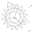
- a conventional sine / cosine signal is formed. This serves to determine the position and together with a 120 ° -structure forms the basis for an absolute position determination ( Fig. 3 ).
- a measuring standard (see Fig. 3 ) is provided on the rotor 08.
- the design of the material measure influences the accuracy of the position determination.
- the design of the sensor elements 08, 09 also makes it possible to detect certain vibration frequencies that allow statements to wear and load the bearing.
- Fig. 3 shows by way of example the possible design of the rotor 08 as the first sensor element in a plan view.
- the rotor 08 shown has sixteen sinusoidal cycles 14 in its outer peripheral region, so that a gear-like shape of the rotor 08 is formed. Through these cycles or their number, the first measuring standard is formed.
- a structure 16 with a material reinforcement can be seen in the radially inner region of the rotor 08.
- a determination of the absolute rotational angular position of the rotor 08 is possible.
- the processing and amplification electronics produce an analog sine / cosine signal for speed detection, and preferably also a digital signal for absolute position determination. In principle, however, any desired signal forms can be used for the transmission and evaluation of the signals.
- the two signal forms are transmitted via a measuring system cable to an external controller.
- the analog sine / cosine signal which is usually used for position control, can be replaced by a fully digital signal. Then transmission to a controller is possible via only one motor line, i. For applications in a motor, the measuring system cable can be saved.
Applications Claiming Priority (1)
| Application Number | Priority Date | Filing Date | Title |
|---|---|---|---|
| DE102009044542A DE102009044542B3 (de) | 2009-11-16 | 2009-11-16 | Wälzlager mit einer Sensoreinheit |
Publications (1)
| Publication Number | Publication Date |
|---|---|
| EP2325654A1 true EP2325654A1 (fr) | 2011-05-25 |
Family
ID=43501164
Family Applications (1)
| Application Number | Title | Priority Date | Filing Date |
|---|---|---|---|
| EP10190337A Withdrawn EP2325654A1 (fr) | 2009-11-16 | 2010-11-08 | Palier à roulement avec capteur |
Country Status (5)
| Country | Link |
|---|---|
| US (1) | US8461827B2 (fr) |
| EP (1) | EP2325654A1 (fr) |
| JP (1) | JP2011107134A (fr) |
| CN (1) | CN102252029A (fr) |
| DE (1) | DE102009044542B3 (fr) |
Cited By (1)
| Publication number | Priority date | Publication date | Assignee | Title |
|---|---|---|---|---|
| FR2979667A1 (fr) * | 2011-09-06 | 2013-03-08 | Snecma | Procede de surveillance du niveau de lubrifiant dans un composant de turbomachine |
Families Citing this family (15)
| Publication number | Priority date | Publication date | Assignee | Title |
|---|---|---|---|---|
| FR2908183B1 (fr) * | 2006-11-07 | 2009-01-23 | Univ Reims Champagne Ardenne | Dispositif et procede de surveillance de l'etat vibratoire d'une machine tournante |
| EP2918523B1 (fr) * | 2014-03-11 | 2016-02-03 | Sick Ag | Détecteur capacitif pour un rouleau et procédé de détection d'objets sur un transporteur à rouleaux |
| US9995344B2 (en) * | 2014-05-19 | 2018-06-12 | Aktiebolaget Skf | Capacitance measurement in a bearing |
| CN103994142B (zh) * | 2014-05-28 | 2016-05-04 | 浙江师范大学 | 一种用于电力设施的大尺度球轴承组件 |
| CN103982556B (zh) * | 2014-05-28 | 2016-05-04 | 浙江师范大学 | 一种用于风力发电机的转速自监测的球轴承 |
| CN103982557B (zh) * | 2014-05-28 | 2016-05-11 | 浙江师范大学 | 一种具有自测量系统的球轴承 |
| DE102015208837B4 (de) * | 2015-05-13 | 2017-03-30 | Schaeffler Technologies AG & Co. KG | Sensoranordnung mit einem Winkelsensor sowie Wälzlageranordnung mit Sensoranordnung |
| DE102015218626A1 (de) | 2015-09-28 | 2017-03-30 | Aktiebolaget Skf | Signalübertragungsvorrichtung für Lager |
| US9891136B2 (en) * | 2015-09-30 | 2018-02-13 | Deere & Company | Methods to determine a bearing setting |
| DE102016116113A1 (de) * | 2016-08-30 | 2018-03-01 | Thyssenkrupp Ag | Lager und Verfahren zur Verschleißüberwachung und/oder Lastmessung |
| DE102017103414B3 (de) * | 2017-02-20 | 2018-02-15 | Schaeffler Technologies AG & Co. KG | Resolverlageranordnung |
| CN111148914B (zh) * | 2017-09-29 | 2022-06-17 | 黑拉有限责任两合公司 | 包括内环、外环及传感器的轴承及包括此种轴承的系统 |
| DE102019125801A1 (de) * | 2019-09-25 | 2021-03-25 | Dr. Ing. H.C. F. Porsche Aktiengesellschaft | Wälzlager mit Sensor und Antriebseinheit |
| CN113295881A (zh) * | 2021-06-17 | 2021-08-24 | 工业互联网创新中心(上海)有限公司 | 一种高精度通用型工业焊机送丝速度测量装置和方法 |
| CN114392146B (zh) * | 2021-12-07 | 2023-11-28 | 奥佳华智能健康科技集团股份有限公司 | 一种按摩椅4d按摩机芯和按摩椅 |
Citations (8)
| Publication number | Priority date | Publication date | Assignee | Title |
|---|---|---|---|---|
| US4092579A (en) * | 1976-12-15 | 1978-05-30 | Contraves Goerz Corporation | Brushless printed circuit resolver |
| US4259637A (en) * | 1977-07-22 | 1981-03-31 | Ransome Hoffmann Pollard Limited | Mechanical assemblies employing sensing means for sensing motion or position |
| US4879552A (en) * | 1985-05-23 | 1989-11-07 | Mitutoyo Mfg. Co., Ltd. | Variable capacitance type encoder |
| EP0395783A1 (fr) | 1989-05-05 | 1990-11-07 | Gmn Georg Müller Nürnberg Ag | Palier à capteur pour mesurer la vitesse de rotation et/ou l'angle de rotation |
| DE19748996C1 (de) | 1997-11-06 | 1999-07-15 | Wolfgang Scharrer | Kugellager mit integriertem Sensor |
| DE10105824A1 (de) | 2001-02-07 | 2002-08-08 | Mercedes Benz Lenkungen Gmbh | Absolutwinkelsensor auf Wälzlagerbasis |
| US20040252032A1 (en) * | 1999-04-19 | 2004-12-16 | Yishay Netzer | Linear electric encoder with facing transmitter and receiver |
| US20050092108A1 (en) * | 2003-11-04 | 2005-05-05 | Andermotion Technologies Llc | Signal-balanced shield electrode configuration for use in capacitive displacement sensing systems and methods |
Family Cites Families (7)
| Publication number | Priority date | Publication date | Assignee | Title |
|---|---|---|---|---|
| US3722296A (en) * | 1971-01-19 | 1973-03-27 | Bendix Corp | Antifriction bearing with compensating flexural pivot in a free axis gyroscope |
| US4429307A (en) * | 1982-01-29 | 1984-01-31 | Dataproducts Corporation | Capacitive transducer with continuous sinusoidal output |
| DE3711062A1 (de) * | 1987-04-02 | 1988-10-20 | Herbert Leypold | Kapazitive absolute positionsmessvorrichtung |
| DE4134354A1 (de) * | 1991-10-17 | 1993-04-22 | Schaeffler Waelzlager Kg | Schwingungsdaempfer |
| DE4215701C1 (en) * | 1992-05-13 | 1993-07-22 | Teldix Gmbh, 6900 Heidelberg, De | Capacitive angle encoder - contains correction capacitor set up to correct for reproducible, angle dependent errors before sealing housing |
| US5409316A (en) * | 1993-04-02 | 1995-04-25 | Precision Handling Devices | Crossed roller bearing |
| US5678933A (en) * | 1995-01-20 | 1997-10-21 | Nsk Ltd. | Speed sensing rolling bearing unit |
-
2009
- 2009-11-16 DE DE102009044542A patent/DE102009044542B3/de active Active
-
2010
- 2010-11-08 EP EP10190337A patent/EP2325654A1/fr not_active Withdrawn
- 2010-11-11 JP JP2010253202A patent/JP2011107134A/ja active Pending
- 2010-11-15 US US12/946,128 patent/US8461827B2/en active Active
- 2010-11-16 CN CN2010105512154A patent/CN102252029A/zh active Pending
Patent Citations (9)
| Publication number | Priority date | Publication date | Assignee | Title |
|---|---|---|---|---|
| US4092579A (en) * | 1976-12-15 | 1978-05-30 | Contraves Goerz Corporation | Brushless printed circuit resolver |
| US4259637A (en) * | 1977-07-22 | 1981-03-31 | Ransome Hoffmann Pollard Limited | Mechanical assemblies employing sensing means for sensing motion or position |
| US4879552A (en) * | 1985-05-23 | 1989-11-07 | Mitutoyo Mfg. Co., Ltd. | Variable capacitance type encoder |
| EP0395783A1 (fr) | 1989-05-05 | 1990-11-07 | Gmn Georg Müller Nürnberg Ag | Palier à capteur pour mesurer la vitesse de rotation et/ou l'angle de rotation |
| DE19748996C1 (de) | 1997-11-06 | 1999-07-15 | Wolfgang Scharrer | Kugellager mit integriertem Sensor |
| US20040252032A1 (en) * | 1999-04-19 | 2004-12-16 | Yishay Netzer | Linear electric encoder with facing transmitter and receiver |
| DE60016395T2 (de) | 1999-04-19 | 2006-02-09 | Netzer Precision Motion Sensors Ltd. | Kapazitiver weggeber |
| DE10105824A1 (de) | 2001-02-07 | 2002-08-08 | Mercedes Benz Lenkungen Gmbh | Absolutwinkelsensor auf Wälzlagerbasis |
| US20050092108A1 (en) * | 2003-11-04 | 2005-05-05 | Andermotion Technologies Llc | Signal-balanced shield electrode configuration for use in capacitive displacement sensing systems and methods |
Non-Patent Citations (2)
| Title |
|---|
| BRASSEUR G: "A robust capacitive angular position sensor", INSTRUMENTATION AND MEASUREMENT TECHNOLOGY CONFERENCE, 1996. IMTC-96. CONFERENCE PROCEEEDINGS. QUALITY MEASUREMENTS: THE INDISPENSABLE BRIDG E BETWEEN THEORY AND REALITY., IEEE BRUSSELS, BELGIUM 4-6 JUNE 1996, NEW YORK, NY, USA,IEEE, US, vol. 2, 4 June 1996 (1996-06-04), pages 1081 - 1086, XP010164039, ISBN: 978-0-7803-3312-3, DOI: 10.1109/IMTC.1996.507331 * |
| TIBOR FABIAN ET AL: "A Robust Capacitive Angular Speed Sensor", IEEE TRANSACTIONS ON INSTRUMENTATION AND MEASUREMENT, IEEE SERVICE CENTER, PISCATAWAY, NJ, US, vol. 47, no. 1, 1 February 1998 (1998-02-01), XP011024420, ISSN: 0018-9456 * |
Cited By (1)
| Publication number | Priority date | Publication date | Assignee | Title |
|---|---|---|---|---|
| FR2979667A1 (fr) * | 2011-09-06 | 2013-03-08 | Snecma | Procede de surveillance du niveau de lubrifiant dans un composant de turbomachine |
Also Published As
| Publication number | Publication date |
|---|---|
| DE102009044542B3 (de) | 2011-05-19 |
| JP2011107134A (ja) | 2011-06-02 |
| US8461827B2 (en) | 2013-06-11 |
| US20110116733A1 (en) | 2011-05-19 |
| CN102252029A (zh) | 2011-11-23 |
Similar Documents
| Publication | Publication Date | Title |
|---|---|---|
| DE102009044542B3 (de) | Wälzlager mit einer Sensoreinheit | |
| EP2105713B1 (fr) | Appareil de mesure de position et son procédé de fonctionnement | |
| EP1906153B1 (fr) | Encodeur et son procédé de fonctionnement | |
| DE69927385T2 (de) | Bürstenloser elektrischer Motor mit zwei senkrechten Hall Wandlern | |
| EP2225142B1 (fr) | Arrangement de detection de l'angle de direction a mesure absolue | |
| EP2265902B1 (fr) | Détecteur d'angle de rotation inductif et procédé d'exploitation d'un détecteur d'angle de rotation inductif | |
| EP2711671B1 (fr) | Appareil de mesure de position et son procédé de fonctionnement | |
| EP3029427B1 (fr) | Dispositif et algorithme destines a la determination d'angle mecanique radial absolu d'un arbre | |
| DE19716985A1 (de) | Vorrichtung zur Ermittlung der Position und/oder Torsion rotierender Wellen | |
| EP2329225B1 (fr) | Capteur de position inductif, système de mesure équipé de ce capteur et procédé pour faire fonctionner un tel capteur de position | |
| EP2743649A1 (fr) | Dispositif de mesure de position inductif | |
| EP2748053A1 (fr) | Capteur combiné visant le couple de braquage et l'angle de braquage | |
| DE102018113379A1 (de) | Drehwinkelerfassungseinrichtung, Drehwinkelerfassungsanordnung, Leistungserfassungsvorrichtung und Verfahren zur Drehwinkelerfassung | |
| DE4129576C2 (de) | Magnetisches Meßsystem zur Drehwinkelmessung | |
| EP3534121A1 (fr) | Capteur de rotation multitour | |
| DE102019127297A1 (de) | Sensorvorrichtung zur Erfassung der Drehwinkelstellung einer drehbeweglichen Welle sowie Lenkungsanordnung eines Fahrzeugs | |
| EP3702737B1 (fr) | Unité de balayage permettant de balayer une échelle d'angle ainsi que dispositif de mesure d'angle doté d'une telle unité de balayage | |
| EP1600737A2 (fr) | Dispositif de mesure d'angle de rotation | |
| EP3707479B1 (fr) | Positionnement de moteurs au moyen d'une mesure capacitive | |
| EP3913349A1 (fr) | Procédé de détermination de la charge d'un arbre d'entrainement | |
| EP3128294A2 (fr) | Capteur de determination de la position angulaire d'un moteur et moteur comprenant un capteur destine a determiner la position angulaire | |
| DE102011087494B4 (de) | Kapazitiver Sensor zur Lage- oder Bewegungserkennung | |
| EP3312566B1 (fr) | Transducteur rotatif destiné à mesurer une variable d'état d'un objet rotatif | |
| EP2905882B1 (fr) | Détection d'un état cinématique d'un composant de machine rotatif | |
| DE102008062849A1 (de) | Messvorrichtung mit Piezoelement |
Legal Events
| Date | Code | Title | Description |
|---|---|---|---|
| PUAI | Public reference made under article 153(3) epc to a published international application that has entered the european phase |
Free format text: ORIGINAL CODE: 0009012 |
|
| AK | Designated contracting states |
Kind code of ref document: A1 Designated state(s): AL AT BE BG CH CY CZ DE DK EE ES FI FR GB GR HR HU IE IS IT LI LT LU LV MC MK MT NL NO PL PT RO RS SE SI SK SM TR |
|
| AX | Request for extension of the european patent |
Extension state: BA ME |
|
| RAP1 | Party data changed (applicant data changed or rights of an application transferred) |
Owner name: INA-DRIVES & MECHATRONICS GMBH & CO OHG Owner name: SCHAEFFLER TECHNOLOGIES AG & CO. KG Owner name: SICK STEGMANN GMBH |
|
| STAA | Information on the status of an ep patent application or granted ep patent |
Free format text: STATUS: THE APPLICATION IS DEEMED TO BE WITHDRAWN |
|
| 18D | Application deemed to be withdrawn |
Effective date: 20111126 |