EP2265902B1 - Détecteur d'angle de rotation inductif et procédé d'exploitation d'un détecteur d'angle de rotation inductif - Google Patents
Détecteur d'angle de rotation inductif et procédé d'exploitation d'un détecteur d'angle de rotation inductif Download PDFInfo
- Publication number
- EP2265902B1 EP2265902B1 EP09730838.1A EP09730838A EP2265902B1 EP 2265902 B1 EP2265902 B1 EP 2265902B1 EP 09730838 A EP09730838 A EP 09730838A EP 2265902 B1 EP2265902 B1 EP 2265902B1
- Authority
- EP
- European Patent Office
- Prior art keywords
- track
- receiver
- signals
- graduation
- period number
- Prior art date
- Legal status (The legal status is an assumption and is not a legal conclusion. Google has not performed a legal analysis and makes no representation as to the accuracy of the status listed.)
- Active
Links
- 230000001939 inductive effect Effects 0.000 title claims description 19
- 238000000034 method Methods 0.000 title claims description 13
- 239000004020 conductor Substances 0.000 claims description 51
- 230000005284 excitation Effects 0.000 claims description 8
- 230000010363 phase shift Effects 0.000 claims 3
- 238000004519 manufacturing process Methods 0.000 description 7
- 239000000758 substrate Substances 0.000 description 7
- 238000005259 measurement Methods 0.000 description 6
- 230000001419 dependent effect Effects 0.000 description 3
- 230000000694 effects Effects 0.000 description 3
- RYGMFSIKBFXOCR-UHFFFAOYSA-N Copper Chemical compound [Cu] RYGMFSIKBFXOCR-UHFFFAOYSA-N 0.000 description 2
- 230000015572 biosynthetic process Effects 0.000 description 2
- 229910052802 copper Inorganic materials 0.000 description 2
- 239000010949 copper Substances 0.000 description 2
- 230000005672 electromagnetic field Effects 0.000 description 2
- 238000011156 evaluation Methods 0.000 description 2
- 230000006698 induction Effects 0.000 description 2
- 238000005192 partition Methods 0.000 description 2
- 238000001514 detection method Methods 0.000 description 1
- 239000003822 epoxy resin Substances 0.000 description 1
- 239000000463 material Substances 0.000 description 1
- 230000000737 periodic effect Effects 0.000 description 1
- 229920000647 polyepoxide Polymers 0.000 description 1
- 238000004804 winding Methods 0.000 description 1
Images


Classifications
-
- G—PHYSICS
- G01—MEASURING; TESTING
- G01D—MEASURING NOT SPECIALLY ADAPTED FOR A SPECIFIC VARIABLE; ARRANGEMENTS FOR MEASURING TWO OR MORE VARIABLES NOT COVERED IN A SINGLE OTHER SUBCLASS; TARIFF METERING APPARATUS; MEASURING OR TESTING NOT OTHERWISE PROVIDED FOR
- G01D5/00—Mechanical means for transferring the output of a sensing member; Means for converting the output of a sensing member to another variable where the form or nature of the sensing member does not constrain the means for converting; Transducers not specially adapted for a specific variable
- G01D5/12—Mechanical means for transferring the output of a sensing member; Means for converting the output of a sensing member to another variable where the form or nature of the sensing member does not constrain the means for converting; Transducers not specially adapted for a specific variable using electric or magnetic means
- G01D5/14—Mechanical means for transferring the output of a sensing member; Means for converting the output of a sensing member to another variable where the form or nature of the sensing member does not constrain the means for converting; Transducers not specially adapted for a specific variable using electric or magnetic means influencing the magnitude of a current or voltage
- G01D5/20—Mechanical means for transferring the output of a sensing member; Means for converting the output of a sensing member to another variable where the form or nature of the sensing member does not constrain the means for converting; Transducers not specially adapted for a specific variable using electric or magnetic means influencing the magnitude of a current or voltage by varying inductance, e.g. by a movable armature
- G01D5/204—Mechanical means for transferring the output of a sensing member; Means for converting the output of a sensing member to another variable where the form or nature of the sensing member does not constrain the means for converting; Transducers not specially adapted for a specific variable using electric or magnetic means influencing the magnitude of a current or voltage by varying inductance, e.g. by a movable armature by influencing the mutual induction between two or more coils
- G01D5/2053—Mechanical means for transferring the output of a sensing member; Means for converting the output of a sensing member to another variable where the form or nature of the sensing member does not constrain the means for converting; Transducers not specially adapted for a specific variable using electric or magnetic means influencing the magnitude of a current or voltage by varying inductance, e.g. by a movable armature by influencing the mutual induction between two or more coils by a movable non-ferromagnetic conductive element
-
- G—PHYSICS
- G01—MEASURING; TESTING
- G01D—MEASURING NOT SPECIALLY ADAPTED FOR A SPECIFIC VARIABLE; ARRANGEMENTS FOR MEASURING TWO OR MORE VARIABLES NOT COVERED IN A SINGLE OTHER SUBCLASS; TARIFF METERING APPARATUS; MEASURING OR TESTING NOT OTHERWISE PROVIDED FOR
- G01D5/00—Mechanical means for transferring the output of a sensing member; Means for converting the output of a sensing member to another variable where the form or nature of the sensing member does not constrain the means for converting; Transducers not specially adapted for a specific variable
- G01D5/12—Mechanical means for transferring the output of a sensing member; Means for converting the output of a sensing member to another variable where the form or nature of the sensing member does not constrain the means for converting; Transducers not specially adapted for a specific variable using electric or magnetic means
- G01D5/244—Mechanical means for transferring the output of a sensing member; Means for converting the output of a sensing member to another variable where the form or nature of the sensing member does not constrain the means for converting; Transducers not specially adapted for a specific variable using electric or magnetic means influencing characteristics of pulses or pulse trains; generating pulses or pulse trains
- G01D5/245—Mechanical means for transferring the output of a sensing member; Means for converting the output of a sensing member to another variable where the form or nature of the sensing member does not constrain the means for converting; Transducers not specially adapted for a specific variable using electric or magnetic means influencing characteristics of pulses or pulse trains; generating pulses or pulse trains using a variable number of pulses in a train
- G01D5/2454—Encoders incorporating incremental and absolute signals
- G01D5/2455—Encoders incorporating incremental and absolute signals with incremental and absolute tracks on the same encoder
- G01D5/2457—Incremental encoders having reference marks
Definitions
- the invention relates to an inductive rotation angle sensor for determining relative angular positions according to the preamble of claim 1 and to a method for operating an inductive rotation angle sensor according to claim 8.
- Inductive rotation angle sensors are used for example in encoders for determining the angular position of two relatively rotatable machine parts.
- excitation coils and receiver coils are applied approximately in the form of interconnects on a common circuit board, which is firmly connected, for example, with a stator of a rotary encoder.
- this printed circuit board there is a further board, which is not infrequently designed as a partial disk, on which periodically spaced electrically conductive and non-conductive surfaces are applied as a division or division structure, and which is rotatably connected to the rotor of the encoder.
- Rotary encoders with inductive rotation angle sensors are frequently used as measuring devices for electric drives, for determining the absolute angular position of corresponding drive shafts.
- Manufacturing tolerances are to be understood hereinafter in particular also cultivation tolerances, which arise during assembly of the rotation angle sensor to a shaft to be measured. Such cultivation tolerances or cultivation inaccuracies can cause, for example, tumbling movements of the rotor or misalignment of the rotor and / or the stator.
- the invention is therefore based on the object to provide a cost-effective inductive rotation angle sensor and a method for Berieb such a rotation angle sensor, by which / which a high signal quality and extremely accurate measurement results can be achieved.
- the inductive rotation angle sensor a printed circuit board, on which an exciter track and a first, second and a third receiver track are applied.
- the rotation angle sensor comprises a dividing element, which is rotatable relative to the printed circuit board and comprises a first and a second graduation track, each consisting in particular of alternately arranged, electrically conductive and non-conductive graduation regions.
- the first and second graduation tracks and the first and second receiver tracks are configured so that within a revolution of the dividing element relative to the printed circuit board, signals having a first period number can be generated by the first receiver track and signals having a second period number can be generated by the second receiver track.
- the dividing element on a third pitch track which may also consist of alternately arranged, electrically conductive and non-conductive division regions, wherein the third divisional track and the third 270leiterbahn are configured so that within a revolution of the dividing element relative to the circuit board through the third 270leiterbahn signals with the first period number can be generated.
- a rotation angle sensor is particularly suitable for reducing measurement errors due to wobbling or skewing of the partition member relative to the circuit board. Likewise, the influence of a skewing of the stator can be reduced.
- the distance of the first pitch track to the axis of rotation differs from the distance of the third pitch track to the axis of rotation.
- the first graduation track has a radius of curvature that is different from the radius of curvature of the third graduation track.
- the innermost graduation track is applied in a region which is bounded by a smaller radius r towards the rotating pocket.
- the outermost graduation track is within a larger radius R, both radii r, R have their origin in the axis of rotation.
- the invention in connection with annular dividing discs which have a comparatively large inner bore. With this specification, the smaller radius r is often comparatively large. In particular, therefore, the invention is advantageously usable when the ratio of the larger radius R to the smaller radius r is smaller than 3/2 (R / r ⁇ 3/2).
- the rotation angle sensor in particular the printed circuit board, comprises a means by which the signals of the third receiver track can be combined with the signals of the first receiver track to form a total signal, wherein from the total signal a relative angular position between the circuit board and partition element error reduced, with respect to manufacturing and mounting tolerances , is determinable.
- the means may for example be designed as an electronic circuit and be designed in particular as an analog electronic circuit.
- the means is an addition or subtraction means, or an addition or subtraction circuit.
- the circuit can only mean a serial or a parallel interconnection of the first with the third receiver track.
- period number is to be understood as the number of signal periods which are generated within one revolution of the dividing element or the dividing disk relative to the printed circuit board by a receiver printed conductor.
- the first period number is smaller than the second period number, in particular, the first period number can assume the value one.
- the first period number is odd and the second period number is even.
- the signals that can be generated by the first receiver track can have a phase offset of 360 ° / (2 * n1) from the signals that can be generated by the third receiver track, where n1 is the value of the first period number of the signals of the first and third receiver tracks represents.
- the printed circuit board has a first receiver track and a third receiver track, wherein the first receiver track comprises two first receiver tracks and the third receiver track comprises two third receiver tracks.
- the invention comprises a method for operating a rotation angle sensor, wherein the rotation angle sensor has a printed circuit board, on which an excitation conductor track and a first, second and third receiver track are applied. Furthermore, the rotation angle sensor has a dividing element which is rotated relative to the printed circuit board during operation and comprises first, second and third graduation tracks, the graduation tracks each consisting in particular of alternately arranged, electrically conductive and nonconductive graduation regions.
- the first, second and third graduation tracks and the first, second and third receiver tracks are configured to generate signals having a first period number and the second receiver track signals having a second period number within one revolution of the divider element relative to the circuit board through the first and third receiver tracks ,
- the signals with the first Period number are combined into a total signal and from the total signal, the relative angular position between the circuit board and the dividing element is determined or generates information about the relative angular position.
- the signals of the first period number are combined into a total signal using an addition or subtraction operation.
- the circuit board has a first receiver track and a third receiver track, wherein the first receiver track comprises two first receiver tracks and the third receiver track comprises two third receiver tracks, so that two total signals can be generated.
- the two total signals have a phase offset of 90 °.
- the rotation angle sensor can also be designed so that more than two total signals can be generated, for example three, which then each have a phase offset of 120 ° or 60 ° to each other.
- the Figures 1-6 show a total of four embodiments of a rotation angle sensor according to the invention.
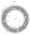
- FIG. 1 is a dividing element in the form of an annular dividing disk 2 shown according to a first embodiment.
- the dividing disc 2 consists of a substrate 2.4, which is made in the embodiments of epoxy resin, and on which three graduation tracks 2.1, 2.2, 2.3 are arranged.
- the graduation tracks 2.1, 2.2, 2.3 are of circular design and are arranged on the substrate 2.4 concentrically with respect to an axis of rotation A with different diameters or radially offset from each other.
- the graduation tracks 2.1, 2.2, 2.3 each consist of a periodic sequence of alternately arranged electrically conductive graduation regions 2.11, 2.21, 2.31 and nonconductive graduation regions 2.12, 2.22, 2.32.
- As material for the electrically conductive division regions 2.11, 2.21, 2.31 copper was applied to the substrate 2.4 in all examples shown. In the non-conductive division regions 2.12, 2.22, 2.32, however, the substrate 2.4 was not coated.
- the first embodiment consist of the two inner graduation tracks 2.1 and 2.3, or the first and the third graduation track 2.1 and 2.3, in the illustrated embodiment in each case from a first semicircular division region 2.11, 2.31 with electrically conductive material, here copper, and in each case a second semicircular division region 2.12 , 2.32 in which no conductive material is arranged.
- the innermost graduation track 2.1 is applied in a region which is limited to the rotary ash A through the radius r.
- the second graduation track 2.2 lies on the substrate 2.4, the second graduation track 2.2 also consisting of a multiplicity of electrically conductive graduation areas 2.21 and non-conductive graduation areas 2.22 arranged therebetween.
- the different division regions 2.21, 2.22 are materially formed here as well as the division regions 2.11, 2.12 of the first and third division tracks 2.1, 2.3.
- the second graduation track 2.2 in the exemplary embodiments illustrated comprises thirty-two periodically arranged, electrically conductive graduation regions 2.21 and correspondingly thirty-two non-conductive graduation regions 2.22 arranged therebetween.
- the second graduation track 2.2 lies within the radius R, wherein the radius R has its origin in the axis of rotation A.
- the annular dividing disk 2 or the substrate 2.4 has a comparatively large inner bore for receiving a shaft 4 to be measured (FIG. FIG. 8 ) on. Accordingly, the ratio R / r is relatively small and is about 1.34 here.
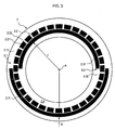
- circuit board 1 comprises as receiver coils in an innermost receiver track 1.1 two receiver tracks 1.11, 1.12, in a middle receiver track 1.3 more two receiver tracks 1.31, 1.32 and in the outermost receiver track 1.2 an additional pair of receiver tracks 1.21, 1.22.
- the associated pairs of receiver traces 1.11, 1.12; 1.21, 1.22; 1.31, 1.32 of a respective receiver track 1.1, 1.2, 1.3 are in this case arranged offset relative to each other.
- 1 exciter tracks 1.4 are provided as excitation coils on the circuit board, which are applied to an inner, a middle and an outer exciter track.
- the circuit board 1 itself has a central bore 1.5 and is designed as a multilayer printed circuit board.
- the dividing disc 2 and the circuit board 1 face each other, so that the axis of rotation A passes through the centers of both elements and at a relative rotation between part plate 2 and circuit board 1 in the circuit board 1 dependent on the respective rotational position angle information by induction effects can be generated. It is unavoidable that the dividing disk 2 relative to the circuit board 1 during the rotational movement also performs wobbling movements, which are caused by manufacturing or cultivation tolerances.
- the exciter printed conductors 1.4 generate a time-varying electromagnetic excitation field in the area of the receiver tracks 1.1, 1.2, 1.3 or in the area of the graduated tracks 2.1, 2.2, 2.3 scanned therewith.
- the exciter printed conductors 1.4 are formed as a plurality of planar-parallel current-carrying individual printed conductors. If the exciter printed conductors 1.4 of a printed conductor unit are all traversed by current in the same direction, then a tubular or cylindrically oriented electromagnetic field is formed around the respective printed conductor unit. The field lines of the resulting electromagnetic field run in the form of concentric circles around the conductor track units, wherein the direction of the field lines in a known manner depends on the current direction in the conductor track units.
- the current direction of the conductor track units directly adjoining a common receiver track 1.1, 1.2, 1.3 or the corresponding interconnection of these track track units is to be chosen opposite, so that the field lines in the area of the receiver tracks 1.1, 1.2, 1.3 are each oriented identically.
- FIGS. 7a and 7b are waveforms of signals S1.11, S1.12; S1.31, S1.32, which are generated by the receiver printed conductors 1.11, 1.12, 1.31, 1.32, wherein for the sake of clarity, only the envelopes of the received voltages are shown here.
- the angular position ⁇ in a range from 0 ° to 360 ° is plotted on the abscissa and the signal level U.
- the signals S1.31, S1.32 are in accordance with the FIG. 7b also discernible deviations from an ideal sinusoidal shape, as well as a non-ideal phase offset and an offset error.
- phase offset between associated receiver tracks 1.11, 1.31; 1.12, 1.32 corresponds to the formula 360 ° / (2 ⁇ n1), so that therefore the receiver conductor 1.11 to the receiver conductor 1.31 is arranged 180 ° out of phase, as well as the receiver conductor 1.12 to the receiver conductor 1.32.
- the same consideration also applies to the division tracks 2.1, 2.3.
- the signals S1.11, S1.12, S1.31, S1.32 are then combined or interconnected so that overall signals S1, S2 according to the FIG. 7c to be obtained.
- the signals S1.11, S1.12 S1.31, S1.32 are subjected to an analogue subtraction.
- the total signals S1, S2 are then demodulated by means of an evaluation in a subsequent step. From the scanning of the graduation tracks 2.1, 2.3 thus results in a relatively coarse, absolute position information within a revolution of the disc 2 about the axis of rotation A.
- the total signals S1, S2 provide a unique absolute position signal within a revolution of a shaft 4 (see FIG. 5 ), regardless of wobbling and / or misalignment of the disc 2 or the circuit board 1.
- a direction detection is also ensured in the rotational movement.
- the invention is particularly advantageous when signals S1.11, S1.12 S1.31, S1.32 having a low period number n1 are combined with signals S1.21, S1.22 having a high period number n2 ,
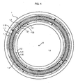
- the first graduation track 2.1 can also be arranged radially outside the second graduation track 2.2. Accordingly, then according FIG. 4 also the first receiver track 1.1 radially outside the second receiver track 1.2, while the third graduation track 2.3 and third receiver track 1.3 are located radially all the way inside.
- the associated circuit boards for the third and fourth embodiments are not shown in the figures, because they do not differ in principle from the circuit boards 1 of the first and second embodiments.
- the third and the fourth embodiment are characterized by an extremely efficient design of the division tracks 2.1 ', 2.3' and the rotation angle sensor.
- the geometric configurations of the second and fourth embodiments have the advantage that the first and the third receiver track 1.1, 1.3 have a comparatively large radial distance. This has the effect that the reduction of the negative influence of manufacturing or cultivation tolerances on the measurement result is particularly effective reach.
- the FIG. 8 shows a rotary encoder, which is equipped with the inductive rotation angle sensor according to the invention.
- the rotary encoder has a fixed housing 3 and the shaft 4 rotatable relative to the housing.
- the shaft 4 serves to receive a rotatable machine part, for example a motor shaft whose angular position ⁇ is to be determined.
- the part plate 2 is fixed against rotation.
- the circuit board 1 is attached to the housing 3. Due to the fact that the annular dividing disk 2 can receive the shaft 4, the dividing disk 2 has a comparatively large inner bore for receiving the shaft 4 to be measured.
Landscapes
- Physics & Mathematics (AREA)
- General Physics & Mathematics (AREA)
- Transmission And Conversion Of Sensor Element Output (AREA)
- Measurement Of Length, Angles, Or The Like Using Electric Or Magnetic Means (AREA)
Claims (15)
- Capteur inductif d'angle de rotation, comportant :une carte de circuit (1) sur laquelle sont placées une piste conductrice d'excitation (1.4) et une première piste conductrice de réception (1.11, 1.12), une deuxième piste conductrice de réception (1.21, 1.22) ainsi qu'une troisième piste conductrice de réception (1.31, 1.32),un élément diviseur (2) apte à tourner par rapport à la carte de circuit (1) et comportant une première piste de division (2.1) ainsi qu'une deuxième piste de division (2.2),la première et la deuxième piste de division (2.1, 2.2) ainsi que la première et la deuxième piste conductrice de réception (1.11, 1.12; 1.21, 1.22) étant configurées de telle sorte qu'à l'intérieur d'un tour de l'élément de division (2) par rapport à la carte de circuit (1), des signaux (S1.11, S1.12) présentant un premier nombre (n1) de périodes peuvent être formés par la première piste conductrice de réception (1.11, 1.12) et des signaux (S1.21, S1.22) présentant un deuxième nombre (n2) de périodes peuvent être formés par la deuxième piste conductrice de réception (1.21, 1.22), caractérisé en ce quel'élément de division (2) présente une troisième piste de division (2.3) et la troisième piste de division (2.3, 2.3') ainsi que la troisième piste conductrice de réception (1.31, 1.32) sont configurées de telle sorte qu'à l'intérieur d'un tour de l'élément de division (2) par rapport à la carte de circuit (1), des signaux (S1.31, S1.32) qui présentent le premier nombre (n1) de périodes peuvent être formés par la troisième piste conductrice de réception (1.31, 1.32).
- Capteur inductif d'angle de rotation selon la revendication 1, caractérisé en ce que le capteur d'angle de rotation et en particulier la carte de circuit (1) comportent un moyen par lequel les signaux (S1.31, S1.32) de la troisième piste conductrice de réception (1.31, 1.32) peuvent être combinés avec les signaux (S1.11, S1.12) de la première piste conductrice de réception (1.11, 1.12) pour former un signal global (S1, S2) à partir duquel une position angulaire relative (ϕ) entre la carte de circuit (1) et l'élément de division (2) peut être déterminée.
- Capteur inductif d'angle de rotation selon les revendications 1 ou 2, caractérisé en ce que le premier nombre (n1) de périodes est plus petit que le deuxième nombre (n2) de périodes.
- Capteur inductif d'angle de rotation selon l'une des revendications précédentes, caractérisé en ce que le premier nombre (n1) de périodes est impair et le deuxième nombre (n2) de périodes est pair.
- Capteur inductif d'angle de rotation selon l'une des revendications précédentes, caractérisé en ce que le premier nombre (n1) de périodes prend la valeur un.
- Capteur inductif d'angle de rotation selon l'une des revendications précédentes, caractérisé en ce que les signaux (S1.11, S1.12) qui peuvent être formés par la première piste conductrice de réception (1.11, 1.12) présentent par rapport aux signaux (S1.31, S1.32) qui peuvent être formés par la troisième piste conductrice de réception (1.31, 1.32) un déphasage de 360°/(2·n1), n1 représentant le premier nombre (n1) de périodes des signaux (S1.11, S1.12, S1.31, S1.32) de la première et de la troisième piste conductrice de réception (1.11, 1.12, 1.31, 1.32).
- Capteur inductif d'angle de rotation selon l'une des revendications précédentes, caractérisé en ce que la carte de circuit (1) présente une première piste de réception (1.1) qui comprend deux premières pistes conductrices de réception (1.11, 1.12) et une troisième piste de réception (1.3) qui comprend deux troisièmes pistes conductrice de réception (1.31, 1.32).
- Procédé de conduite d'un capteur d'angle de rotation, le capteur d'angle de rotation présentant :une carte de circuit (1) sur laquelle sont placées une piste conductrice d'excitation (1.4) et une première piste conductrice de réception (1.11, 1.12), une deuxième piste conductrice de réception (1.21, 1.22) ainsi qu'une troisième piste conductrice de réception (1.31, 1.32),un élément diviseur (2) apte à tourner par rapport à la carte de circuit (1) et comportant une première piste de division (2.1), une deuxième piste de division (2.2) et une troisième piste de division (2.3, 2.3'),la première, la deuxième et la troisième piste de division (2.1, 2.2, 2.3, 2.3') ainsi que la première, la deuxième et la troisième piste conductrice de réception (1.11, 1.12; 1.21, 1.22, 1.31, 1.32) étant configurées de telle sorte qu'à l'intérieur d'un tour de l'élément de division (2) par rapport à la carte de circuit (1), des signaux (S1.11, S1.12; S1.31, S1.32) présentant un premier nombre (n1) de périodes peuvent être formés par la première et la troisième piste conductrice de réception (1.11, 1.12, 1.31, 1.32) et des signaux (S1.21, S1.22) présentant un deuxième nombre (n2) de périodes peuvent être formés par la deuxième piste conductrice de réception (1.21, 1.22),les signaux (S1.11, S1.12, S1.31, S1.32) présentant le premier nombre (n1) de périodes pouvant être combinés en un signal global (S1, S2), la position angulaire relative (ϕ) entre la carte de circuit (1) et l'élément de division (2) étant déterminée à partir du signal global (S1, S2).
- Procédé selon la revendication 8, dans lequel les signaux (S1.11, S1.12, S1.31, S1.32) qui présentent le premier nombre (n1) de périodes sont combinés en un signal global (S1, S2) par recours à une opération d'addition ou de soustraction.
- Procédé selon les revendications 8 ou 9, dans lequel le premier nombre (n1) de périodes est plus petit que le deuxième nombre (n2) de périodes.
- Procédé selon les revendications 8, 9 ou 10, dans lequel le premier nombre (n1) de périodes est impair et le deuxième nombre (n2) de périodes est pair.
- Procédé selon l'une des revendications 8 à 11, dans lequel le premier nombre (n1) de périodes prend la valeur un.
- Procédé selon l'une des revendications 8 à 12, dans lequel les signaux combinés (S1.11, S1.12, S1.31, S1.32) présentent un déphasage un déphasage de 360°/(2·n1), n1 représentant le premier nombre (n1) de périodes des signaux (S1.11, S1.12, S1.31, S1.32) de la première et de la troisième piste conductrice de réception (1.11, 1.12, 1.31, 1.32).
- Procédé selon l'une des revendications 8 à 13, dans lequel la carte de circuit (1) présente une première piste de réception (1.1) qui comprend deux premières pistes conductrices de réception (1.11, 1.12) et une troisième piste de réception (1.3) qui comprend deux troisièmes pistes conductrice de réception (1.31, 1.32), de telle sorte que deux signaux globaux (S1, S2) peuvent être formés.
- Procédé selon la revendication 14, dans lequel les deux signaux globaux (S1, S2) présentent un déphasage de 90°.
Applications Claiming Priority (2)
| Application Number | Priority Date | Filing Date | Title |
|---|---|---|---|
| DE102008017857A DE102008017857A1 (de) | 2008-04-09 | 2008-04-09 | Induktiver Drehwinkelsensor und Verfahren zum Betrieb eines induktiven Drehwinkelsensors |
| PCT/EP2009/053427 WO2009124836A1 (fr) | 2008-04-09 | 2009-03-24 | Détecteur d’angle de rotation inductif et procédé d’exploitation d’un détecteur d’angle de rotation inductif |
Publications (2)
| Publication Number | Publication Date |
|---|---|
| EP2265902A1 EP2265902A1 (fr) | 2010-12-29 |
| EP2265902B1 true EP2265902B1 (fr) | 2014-05-07 |
Family
ID=40688311
Family Applications (1)
| Application Number | Title | Priority Date | Filing Date |
|---|---|---|---|
| EP09730838.1A Active EP2265902B1 (fr) | 2008-04-09 | 2009-03-24 | Détecteur d'angle de rotation inductif et procédé d'exploitation d'un détecteur d'angle de rotation inductif |
Country Status (6)
| Country | Link |
|---|---|
| US (1) | US8278911B2 (fr) |
| EP (1) | EP2265902B1 (fr) |
| JP (1) | JP5314125B2 (fr) |
| CN (1) | CN101990628B (fr) |
| DE (1) | DE102008017857A1 (fr) |
| WO (1) | WO2009124836A1 (fr) |
Families Citing this family (17)
| Publication number | Priority date | Publication date | Assignee | Title |
|---|---|---|---|---|
| US20110207578A1 (en) * | 2010-02-23 | 2011-08-25 | Avago Technologies Ecbu (Singapore) Pte, Ltd. | Harmonic Gear Multi-Turn Encoder |
| DE102011078956A1 (de) | 2011-07-11 | 2013-01-17 | Dr. Johannes Heidenhain Gmbh | Teilungsträger für eine Positionsmesseinrichtung und Verfahren zur Herstellung des Teilungsträgers |
| US9163926B2 (en) * | 2012-01-25 | 2015-10-20 | Mitutoyo Corporation | Inductive detection type rotary encoder |
| WO2013134715A2 (fr) | 2012-03-08 | 2013-09-12 | Husqvarna Ab | Système de gestion de flotte d'équipements motorisés d'extérieur doté d'une fonction de surveillance des performances des utilisateurs |
| DE102012223037A1 (de) * | 2012-12-13 | 2014-06-18 | Dr. Johannes Heidenhain Gmbh | Induktive Positionsmesseinrichtung |
| FR3027103B1 (fr) * | 2014-10-08 | 2017-11-24 | Continental Automotive France | Ensemble de capteur de position angulaire pour moteur hybride de vehicule automobile a arbre commun |
| DE102016201851A1 (de) * | 2016-02-08 | 2017-08-10 | Robert Bosch Gmbh | Sensorvorrichtung zur Bestimmung mindestens einer Rotationseigenschaft eines rotierenden Elements |
| JP6245410B1 (ja) * | 2017-01-27 | 2017-12-13 | 三菱電機株式会社 | 電磁界プローブ |
| EP3803277B1 (fr) * | 2018-05-24 | 2022-09-28 | Bosch Car Multimedia Portugal, S.A. | Capteur de position linéaire |
| CN109631958B (zh) * | 2018-11-28 | 2021-03-02 | 赛卓电子科技(上海)有限公司 | 位置编码器 |
| EP4012349B1 (fr) | 2020-12-08 | 2023-03-15 | Dr. Johannes Heidenhain GmbH | Élément de détection et dispositif de mesure de position inductif pourvu dudit élément de détection |
| US11598654B2 (en) * | 2020-12-14 | 2023-03-07 | Microchip Technology Inc. | High resolution angular inductive sensor and associated method of use |
| US11898887B2 (en) | 2021-03-25 | 2024-02-13 | Microchip Technology Incorporated | Sense coil for inductive rotational-position sensing, and related devices, systems, and methods |
| US11994387B2 (en) * | 2021-04-13 | 2024-05-28 | Infineon Technologies Ag | Inductive sensor with improved safety |
| DE112022003815T5 (de) | 2021-08-05 | 2024-05-29 | Microchip Technology Incorporated | Induktive winkelpositionssensoren und zugehörige vorrichtungen, systeme und verfahren |
| EP4230967B1 (fr) * | 2022-02-22 | 2024-04-10 | Dr. Johannes Heidenhain GmbH | Élément palpeur et dispositif inductif de mesure de position pourvu dudit élément palpeur |
| EP4421453A1 (fr) * | 2023-02-23 | 2024-08-28 | Dr. Johannes Heidenhain GmbH | Elément de balayage pour un dispositif inductif de mesure d'angle |
Family Cites Families (6)
| Publication number | Priority date | Publication date | Assignee | Title |
|---|---|---|---|---|
| JP4001989B2 (ja) * | 1996-11-29 | 2007-10-31 | ドクトル・ヨハネス・ハイデンハイン・ゲゼルシヤフト・ミツト・ベシユレンクテル・ハフツング | 位置測定装置の走査部材 |
| JP2000028396A (ja) * | 1998-07-07 | 2000-01-28 | Matsushita Electric Ind Co Ltd | 角度検出装置 |
| DE10158223B4 (de) * | 2001-11-16 | 2017-10-05 | Dr. Johannes Heidenhain Gmbh | Drehwinkel-Messgerät |
| CN1441230A (zh) * | 2002-11-08 | 2003-09-10 | 许建平 | 磁感应物理量传感器 |
| JP4869769B2 (ja) * | 2005-04-19 | 2012-02-08 | 株式会社ミツトヨ | アブソリュートロータリエンコーダ及びマイクロメータ |
| DE102006046531A1 (de) * | 2006-09-29 | 2008-04-03 | Dr. Johannes Heidenhain Gmbh | Drehgeber und Verfahren zu dessen Betrieb |
-
2008
- 2008-04-09 DE DE102008017857A patent/DE102008017857A1/de not_active Withdrawn
-
2009
- 2009-03-24 CN CN200980113191XA patent/CN101990628B/zh active Active
- 2009-03-24 JP JP2011503396A patent/JP5314125B2/ja active Active
- 2009-03-24 EP EP09730838.1A patent/EP2265902B1/fr active Active
- 2009-03-24 WO PCT/EP2009/053427 patent/WO2009124836A1/fr active Application Filing
- 2009-03-24 US US12/935,218 patent/US8278911B2/en active Active
Also Published As
| Publication number | Publication date |
|---|---|
| DE102008017857A1 (de) | 2009-10-15 |
| WO2009124836A1 (fr) | 2009-10-15 |
| US8278911B2 (en) | 2012-10-02 |
| US20110068777A1 (en) | 2011-03-24 |
| JP5314125B2 (ja) | 2013-10-16 |
| EP2265902A1 (fr) | 2010-12-29 |
| CN101990628A (zh) | 2011-03-23 |
| CN101990628B (zh) | 2012-09-05 |
| JP2011516872A (ja) | 2011-05-26 |
Similar Documents
| Publication | Publication Date | Title |
|---|---|---|
| EP2265902B1 (fr) | Détecteur d'angle de rotation inductif et procédé d'exploitation d'un détecteur d'angle de rotation inductif | |
| EP1475604B1 (fr) | Capteur d'angle inductif | |
| EP2743649B1 (fr) | Dispositif de mesure de position inductif | |
| EP2711671B1 (fr) | Appareil de mesure de position et son procédé de fonctionnement | |
| EP2329225B1 (fr) | Capteur de position inductif, système de mesure équipé de ce capteur et procédé pour faire fonctionner un tel capteur de position | |
| DE102009044542B3 (de) | Wälzlager mit einer Sensoreinheit | |
| WO2018234108A1 (fr) | Capteur d'angle de rotation | |
| EP3420316A1 (fr) | Capteur d'angle de rotation | |
| EP2102618A1 (fr) | Ensemble de capteur de couple | |
| EP1906153A2 (fr) | Encodeur et son procédé de fonctionnement | |
| WO2009068695A1 (fr) | Arrangement de détection de l'angle de direction à mesure absolue | |
| WO2013026921A1 (fr) | Capteur combiné visant le couple de braquage et l'angle de braquage | |
| EP4012350B1 (fr) | Élément de détection et dispositif de mesure de position inductif pourvu dudit élément de détection | |
| DE19601242A1 (de) | Versatz-Erfassungseinrichtung | |
| EP4012349B1 (fr) | Élément de détection et dispositif de mesure de position inductif pourvu dudit élément de détection | |
| DE102023200775A1 (de) | Abtastelement und induktive Positionsmesseinrichtung mit diesem Abtastelement | |
| EP4170289B1 (fr) | Dispositif inductif de mesure d'angle | |
| EP3901582B1 (fr) | Dispositif inductif de mesure d'angle | |
| EP3853558A1 (fr) | Unité de détection pour un système capteur-transmetteur et système capteur-transmetteur équipé d'une telle unité de détection | |
| EP4273507B1 (fr) | Élément de détection et dispositif inductif de mesure de position pourvu dudit élément palpeur |
Legal Events
| Date | Code | Title | Description |
|---|---|---|---|
| PUAI | Public reference made under article 153(3) epc to a published international application that has entered the european phase |
Free format text: ORIGINAL CODE: 0009012 |
|
| 17P | Request for examination filed |
Effective date: 20101109 |
|
| AK | Designated contracting states |
Kind code of ref document: A1 Designated state(s): AT BE BG CH CY CZ DE DK EE ES FI FR GB GR HR HU IE IS IT LI LT LU LV MC MK MT NL NO PL PT RO SE SI SK TR |
|
| AX | Request for extension of the european patent |
Extension state: AL BA RS |
|
| DAX | Request for extension of the european patent (deleted) | ||
| GRAP | Despatch of communication of intention to grant a patent |
Free format text: ORIGINAL CODE: EPIDOSNIGR1 |
|
| INTG | Intention to grant announced |
Effective date: 20140218 |
|
| GRAS | Grant fee paid |
Free format text: ORIGINAL CODE: EPIDOSNIGR3 |
|
| GRAA | (expected) grant |
Free format text: ORIGINAL CODE: 0009210 |
|
| AK | Designated contracting states |
Kind code of ref document: B1 Designated state(s): AT BE BG CH CY CZ DE DK EE ES FI FR GB GR HR HU IE IS IT LI LT LU LV MC MK MT NL NO PL PT RO SE SI SK TR |
|
| REG | Reference to a national code |
Ref country code: GB Ref legal event code: FG4D Free format text: NOT ENGLISH |
|
| REG | Reference to a national code |
Ref country code: AT Ref legal event code: REF Ref document number: 667030 Country of ref document: AT Kind code of ref document: T Effective date: 20140515 |
|
| REG | Reference to a national code |
Ref country code: IE Ref legal event code: FG4D Free format text: LANGUAGE OF EP DOCUMENT: GERMAN |
|
| REG | Reference to a national code |
Ref country code: DE Ref legal event code: R096 Ref document number: 502009009350 Country of ref document: DE Effective date: 20140618 |
|
| REG | Reference to a national code |
Ref country code: NL Ref legal event code: VDEP Effective date: 20140507 |
|
| REG | Reference to a national code |
Ref country code: LT Ref legal event code: MG4D |
|
| PG25 | Lapsed in a contracting state [announced via postgrant information from national office to epo] |
Ref country code: CY Free format text: LAPSE BECAUSE OF FAILURE TO SUBMIT A TRANSLATION OF THE DESCRIPTION OR TO PAY THE FEE WITHIN THE PRESCRIBED TIME-LIMIT Effective date: 20140507 Ref country code: IS Free format text: LAPSE BECAUSE OF FAILURE TO SUBMIT A TRANSLATION OF THE DESCRIPTION OR TO PAY THE FEE WITHIN THE PRESCRIBED TIME-LIMIT Effective date: 20140907 Ref country code: NO Free format text: LAPSE BECAUSE OF FAILURE TO SUBMIT A TRANSLATION OF THE DESCRIPTION OR TO PAY THE FEE WITHIN THE PRESCRIBED TIME-LIMIT Effective date: 20140807 Ref country code: LT Free format text: LAPSE BECAUSE OF FAILURE TO SUBMIT A TRANSLATION OF THE DESCRIPTION OR TO PAY THE FEE WITHIN THE PRESCRIBED TIME-LIMIT Effective date: 20140507 Ref country code: FI Free format text: LAPSE BECAUSE OF FAILURE TO SUBMIT A TRANSLATION OF THE DESCRIPTION OR TO PAY THE FEE WITHIN THE PRESCRIBED TIME-LIMIT Effective date: 20140507 Ref country code: GR Free format text: LAPSE BECAUSE OF FAILURE TO SUBMIT A TRANSLATION OF THE DESCRIPTION OR TO PAY THE FEE WITHIN THE PRESCRIBED TIME-LIMIT Effective date: 20140808 |
|
| PG25 | Lapsed in a contracting state [announced via postgrant information from national office to epo] |
Ref country code: LV Free format text: LAPSE BECAUSE OF FAILURE TO SUBMIT A TRANSLATION OF THE DESCRIPTION OR TO PAY THE FEE WITHIN THE PRESCRIBED TIME-LIMIT Effective date: 20140507 Ref country code: ES Free format text: LAPSE BECAUSE OF FAILURE TO SUBMIT A TRANSLATION OF THE DESCRIPTION OR TO PAY THE FEE WITHIN THE PRESCRIBED TIME-LIMIT Effective date: 20140507 Ref country code: HR Free format text: LAPSE BECAUSE OF FAILURE TO SUBMIT A TRANSLATION OF THE DESCRIPTION OR TO PAY THE FEE WITHIN THE PRESCRIBED TIME-LIMIT Effective date: 20140507 Ref country code: PL Free format text: LAPSE BECAUSE OF FAILURE TO SUBMIT A TRANSLATION OF THE DESCRIPTION OR TO PAY THE FEE WITHIN THE PRESCRIBED TIME-LIMIT Effective date: 20140507 Ref country code: SE Free format text: LAPSE BECAUSE OF FAILURE TO SUBMIT A TRANSLATION OF THE DESCRIPTION OR TO PAY THE FEE WITHIN THE PRESCRIBED TIME-LIMIT Effective date: 20140507 |
|
| PG25 | Lapsed in a contracting state [announced via postgrant information from national office to epo] |
Ref country code: PT Free format text: LAPSE BECAUSE OF FAILURE TO SUBMIT A TRANSLATION OF THE DESCRIPTION OR TO PAY THE FEE WITHIN THE PRESCRIBED TIME-LIMIT Effective date: 20140908 |
|
| PG25 | Lapsed in a contracting state [announced via postgrant information from national office to epo] |
Ref country code: SK Free format text: LAPSE BECAUSE OF FAILURE TO SUBMIT A TRANSLATION OF THE DESCRIPTION OR TO PAY THE FEE WITHIN THE PRESCRIBED TIME-LIMIT Effective date: 20140507 Ref country code: EE Free format text: LAPSE BECAUSE OF FAILURE TO SUBMIT A TRANSLATION OF THE DESCRIPTION OR TO PAY THE FEE WITHIN THE PRESCRIBED TIME-LIMIT Effective date: 20140507 Ref country code: RO Free format text: LAPSE BECAUSE OF FAILURE TO SUBMIT A TRANSLATION OF THE DESCRIPTION OR TO PAY THE FEE WITHIN THE PRESCRIBED TIME-LIMIT Effective date: 20140507 Ref country code: DK Free format text: LAPSE BECAUSE OF FAILURE TO SUBMIT A TRANSLATION OF THE DESCRIPTION OR TO PAY THE FEE WITHIN THE PRESCRIBED TIME-LIMIT Effective date: 20140507 |
|
| REG | Reference to a national code |
Ref country code: DE Ref legal event code: R097 Ref document number: 502009009350 Country of ref document: DE |
|
| PG25 | Lapsed in a contracting state [announced via postgrant information from national office to epo] |
Ref country code: NL Free format text: LAPSE BECAUSE OF FAILURE TO SUBMIT A TRANSLATION OF THE DESCRIPTION OR TO PAY THE FEE WITHIN THE PRESCRIBED TIME-LIMIT Effective date: 20140507 |
|
| PLBE | No opposition filed within time limit |
Free format text: ORIGINAL CODE: 0009261 |
|
| STAA | Information on the status of an ep patent application or granted ep patent |
Free format text: STATUS: NO OPPOSITION FILED WITHIN TIME LIMIT |
|
| 26N | No opposition filed |
Effective date: 20150210 |
|
| REG | Reference to a national code |
Ref country code: DE Ref legal event code: R097 Ref document number: 502009009350 Country of ref document: DE Effective date: 20150210 |
|
| PG25 | Lapsed in a contracting state [announced via postgrant information from national office to epo] |
Ref country code: SI Free format text: LAPSE BECAUSE OF FAILURE TO SUBMIT A TRANSLATION OF THE DESCRIPTION OR TO PAY THE FEE WITHIN THE PRESCRIBED TIME-LIMIT Effective date: 20140507 |
|
| PG25 | Lapsed in a contracting state [announced via postgrant information from national office to epo] |
Ref country code: LU Free format text: LAPSE BECAUSE OF FAILURE TO SUBMIT A TRANSLATION OF THE DESCRIPTION OR TO PAY THE FEE WITHIN THE PRESCRIBED TIME-LIMIT Effective date: 20150324 Ref country code: MC Free format text: LAPSE BECAUSE OF FAILURE TO SUBMIT A TRANSLATION OF THE DESCRIPTION OR TO PAY THE FEE WITHIN THE PRESCRIBED TIME-LIMIT Effective date: 20140507 |
|
| REG | Reference to a national code |
Ref country code: CH Ref legal event code: PL |
|
| REG | Reference to a national code |
Ref country code: IE Ref legal event code: MM4A |
|
| PG25 | Lapsed in a contracting state [announced via postgrant information from national office to epo] |
Ref country code: LI Free format text: LAPSE BECAUSE OF NON-PAYMENT OF DUE FEES Effective date: 20150331 Ref country code: IE Free format text: LAPSE BECAUSE OF NON-PAYMENT OF DUE FEES Effective date: 20150324 Ref country code: CH Free format text: LAPSE BECAUSE OF NON-PAYMENT OF DUE FEES Effective date: 20150331 |
|
| REG | Reference to a national code |
Ref country code: FR Ref legal event code: PLFP Year of fee payment: 8 |
|
| REG | Reference to a national code |
Ref country code: AT Ref legal event code: MM01 Ref document number: 667030 Country of ref document: AT Kind code of ref document: T Effective date: 20150324 |
|
| PG25 | Lapsed in a contracting state [announced via postgrant information from national office to epo] |
Ref country code: AT Free format text: LAPSE BECAUSE OF NON-PAYMENT OF DUE FEES Effective date: 20150324 |
|
| PG25 | Lapsed in a contracting state [announced via postgrant information from national office to epo] |
Ref country code: MT Free format text: LAPSE BECAUSE OF FAILURE TO SUBMIT A TRANSLATION OF THE DESCRIPTION OR TO PAY THE FEE WITHIN THE PRESCRIBED TIME-LIMIT Effective date: 20140507 |
|
| REG | Reference to a national code |
Ref country code: FR Ref legal event code: PLFP Year of fee payment: 9 |
|
| PG25 | Lapsed in a contracting state [announced via postgrant information from national office to epo] |
Ref country code: BG Free format text: LAPSE BECAUSE OF FAILURE TO SUBMIT A TRANSLATION OF THE DESCRIPTION OR TO PAY THE FEE WITHIN THE PRESCRIBED TIME-LIMIT Effective date: 20140507 Ref country code: HU Free format text: LAPSE BECAUSE OF FAILURE TO SUBMIT A TRANSLATION OF THE DESCRIPTION OR TO PAY THE FEE WITHIN THE PRESCRIBED TIME-LIMIT; INVALID AB INITIO Effective date: 20090324 |
|
| PG25 | Lapsed in a contracting state [announced via postgrant information from national office to epo] |
Ref country code: BE Free format text: LAPSE BECAUSE OF NON-PAYMENT OF DUE FEES Effective date: 20150331 |
|
| PG25 | Lapsed in a contracting state [announced via postgrant information from national office to epo] |
Ref country code: TR Free format text: LAPSE BECAUSE OF FAILURE TO SUBMIT A TRANSLATION OF THE DESCRIPTION OR TO PAY THE FEE WITHIN THE PRESCRIBED TIME-LIMIT Effective date: 20140507 |
|
| REG | Reference to a national code |
Ref country code: FR Ref legal event code: PLFP Year of fee payment: 10 |
|
| PG25 | Lapsed in a contracting state [announced via postgrant information from national office to epo] |
Ref country code: MK Free format text: LAPSE BECAUSE OF FAILURE TO SUBMIT A TRANSLATION OF THE DESCRIPTION OR TO PAY THE FEE WITHIN THE PRESCRIBED TIME-LIMIT Effective date: 20140507 |
|
| PGFP | Annual fee paid to national office [announced via postgrant information from national office to epo] |
Ref country code: FR Payment date: 20210323 Year of fee payment: 13 |
|
| PGFP | Annual fee paid to national office [announced via postgrant information from national office to epo] |
Ref country code: CZ Payment date: 20210324 Year of fee payment: 13 |
|
| PG25 | Lapsed in a contracting state [announced via postgrant information from national office to epo] |
Ref country code: CZ Free format text: LAPSE BECAUSE OF NON-PAYMENT OF DUE FEES Effective date: 20220324 |
|
| PG25 | Lapsed in a contracting state [announced via postgrant information from national office to epo] |
Ref country code: FR Free format text: LAPSE BECAUSE OF NON-PAYMENT OF DUE FEES Effective date: 20220331 |
|
| PGFP | Annual fee paid to national office [announced via postgrant information from national office to epo] |
Ref country code: IT Payment date: 20230328 Year of fee payment: 15 |
|
| PGFP | Annual fee paid to national office [announced via postgrant information from national office to epo] |
Ref country code: DE Payment date: 20240320 Year of fee payment: 16 Ref country code: GB Payment date: 20240320 Year of fee payment: 16 |