EP2325464A2 - Dispositif de mesure, conduit d'air frais, dispositif d'air frais et élément de guidage du flux d'air - Google Patents
Dispositif de mesure, conduit d'air frais, dispositif d'air frais et élément de guidage du flux d'air Download PDFInfo
- Publication number
- EP2325464A2 EP2325464A2 EP10190846A EP10190846A EP2325464A2 EP 2325464 A2 EP2325464 A2 EP 2325464A2 EP 10190846 A EP10190846 A EP 10190846A EP 10190846 A EP10190846 A EP 10190846A EP 2325464 A2 EP2325464 A2 EP 2325464A2
- Authority
- EP
- European Patent Office
- Prior art keywords
- sectional area
- cross
- flow
- fresh air
- measuring device
- Prior art date
- Legal status (The legal status is an assumption and is not a legal conclusion. Google has not performed a legal analysis and makes no representation as to the accuracy of the status listed.)
- Withdrawn
Links
Images
Classifications
-
- F—MECHANICAL ENGINEERING; LIGHTING; HEATING; WEAPONS; BLASTING
- F02—COMBUSTION ENGINES; HOT-GAS OR COMBUSTION-PRODUCT ENGINE PLANTS
- F02D—CONTROLLING COMBUSTION ENGINES
- F02D41/00—Electrical control of supply of combustible mixture or its constituents
- F02D41/02—Circuit arrangements for generating control signals
- F02D41/18—Circuit arrangements for generating control signals by measuring intake air flow
-
- G—PHYSICS
- G01—MEASURING; TESTING
- G01F—MEASURING VOLUME, VOLUME FLOW, MASS FLOW OR LIQUID LEVEL; METERING BY VOLUME
- G01F1/00—Measuring the volume flow or mass flow of fluid or fluent solid material wherein the fluid passes through a meter in a continuous flow
- G01F1/68—Measuring the volume flow or mass flow of fluid or fluent solid material wherein the fluid passes through a meter in a continuous flow by using thermal effects
- G01F1/684—Structural arrangements; Mounting of elements, e.g. in relation to fluid flow
- G01F1/6842—Structural arrangements; Mounting of elements, e.g. in relation to fluid flow with means for influencing the fluid flow
-
- G—PHYSICS
- G01—MEASURING; TESTING
- G01F—MEASURING VOLUME, VOLUME FLOW, MASS FLOW OR LIQUID LEVEL; METERING BY VOLUME
- G01F15/00—Details of, or accessories for, apparatus of groups G01F1/00 - G01F13/00 insofar as such details or appliances are not adapted to particular types of such apparatus
-
- G—PHYSICS
- G01—MEASURING; TESTING
- G01F—MEASURING VOLUME, VOLUME FLOW, MASS FLOW OR LIQUID LEVEL; METERING BY VOLUME
- G01F5/00—Measuring a proportion of the volume flow
Definitions
- the present invention relates to a measuring device for measuring an air mass of an air flow in a fresh air duct of an internal combustion engine, in particular a motor vehicle, having the features of the preamble of claim 1.
- the invention also relates to a fresh air system equipped with such a measuring device and a fresh air duct equipped with such a measuring device and a flow guide element for such a measuring device.
- a measuring device for measuring an air mass of an air flow in a fresh air passage of an internal combustion engine which comprises an air mass sensor.
- the air mass sensor has a measuring cross-sectional area, which is acted upon for air mass measurement with a part of the guided in the fresh air duct air flow.
- the measuring cross-sectional area is small compared to a cross-sectional area of the fresh air passage in the region of the air mass sensor.
- a rectifier structure is installed in the fresh air duct in the region of the air mass sensor in order to achieve a homogenization of the air flow.
- Measuring devices of this type are required in internal combustion engines for detecting the supplied air mass in order to operate the engine control optimally. Since the measuring cross-sectional area of the air mass sensors used here is significantly smaller than the channel cross-sectional area through which the air flow flows, a comparison takes place via characteristic diagrams, which in particular also take into account a velocity profile within the channel cross-sectional area. However, it has been shown that fresh air filters which can be arranged upstream of the measuring device in the fresh air duct, depending on their load state, produce a more or less strong change in the velocity profile in the channel cross section.
- the present invention is concerned with the problem of demonstrating for a measuring device of the type mentioned above or for a fresh air duct equipped therewith a possibility to reduce the influence of a changing velocity profile within the fresh air channel on the mass measurement.
- the invention is based on the general idea to equip the air mass sensor with a flow guide element having a flow-through inlet cross-sectional area and a flow-through outlet cross-sectional area, which are interconnected via a laterally closed air duct.
- the outlet cross-sectional area corresponds to the measuring cross-sectional area, while the inlet cross-sectional area has a geometry deviating from the outlet cross-sectional area.
- the air duct creates a low-loss transition from the inlet cross-sectional area to the outlet cross-sectional area.
- the proposal according to the invention makes it possible to provide an inlet cross-sectional area which is a representative section of the channel cross-sectional area can pick out what a changing velocity profile within the channel cross-section can be better detected.
- At least one one-dimensional integration measurement can be carried out without the measuring cross-sectional area of the air mass sensor having to be changed for this purpose. Due to the one-dimensional integration of the velocity distribution within a representative region of the channel cross-section, profile changes in the velocity distribution can be detected with increased reliability and taken into account in the mass determination.
- the inlet cross-sectional area may deviate a maximum of 15% or a maximum of 10% from the outlet cross-sectional area.
- An embodiment is preferred in which the inlet cross-sectional area is the same size as the outlet cross-sectional area.
- the formulations "maximum” and “equal size” are understood to mean that deviations may be present within the usual manufacturing tolerances. The same applies to other dimensions or relationships in the present context.
- the constant areas or only minimally varying areas at the inlet and the outlet reduce the influence on the mass measurement. In particular, this can also be used to avoid or at least reduce a rise in pressure or an increase in the throughflow resistance in the fresh air duct by attaching the flow guiding element.
- the inlet cross-sectional area can be designed slit-shaped, whereby the aforementioned one-dimensional measurement is made particularly simple.
- the flow guide element may be a separately manufactured component with respect to the air mass sensor, which component may be attached to the air mass sensor in a suitable manner.
- the flow guide element can be designed so that it can be clipped to the air mass sensor.
- the flow guide element can thereby be used for retrofitting a conventional air mass sensor.
- a conventional air mass sensor does not have to be modified or only slightly modified.
- the air mass sensor may comprise a sensor housing which encloses the measuring cross-sectional area and on which the flow-guiding element is integrally formed.
- This integral design is characterized by a reduced flow resistance.
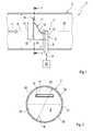
- FIG. 1 includes a fresh air system 1 shown here only partially to supply a not shown internal combustion engine with fresh air a fresh air duct 2, in which an air flow 3 is guided.
- the internal combustion engine may be arranged together with the fresh air system 1 in a motor vehicle.
- the fresh air duct 2 is equipped with a measuring device 4, by means of which an air mass of the air flow 3 guided in the fresh air duct 2 can be measured.
- the measuring device 4 has an air mass sensor 5, which is positioned in the example via a holder 6 in the fresh air channel 2.
- the air mass sensor 5 has a measuring cross-sectional area 7. This is significantly smaller than a flow-through channel cross-sectional area 8 in the region of the measuring device 4.
- the measuring cross-sectional area 7 is a maximum of 10% or maximum 5% of the channel cross-sectional area 8 in the region of the air mass sensor 5.
- the air mass sensor 5 is positioned in the fresh air channel 2 so that its measuring cross-sectional area 7 is subjected to a part of the air flow 3 for air mass measurement.
- an air filter not shown here may be arranged in the fresh air duct 2 upstream of the measuring device 4.
- the air mass sensor 5 With the aid of the air mass sensor 5 generated electrical signals are fed according to a double arrow 9 to a transmitter 10, which also forms a part of the measuring device 4 and converts, for example by means of a map, the measured values determined by the air mass sensor 5 in air masses.
- the air mass sensor 5 may be configured for example as H Corporationfilmmesser.
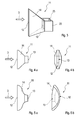
- the air mass sensor 5 has a flow guide element 11. This comprises a flow-through inlet cross-sectional area 12, a flow-through outlet cross-sectional area 13 and an air duct 14.
- the air duct 14 leads from the inlet cross-sectional area 12 to the outlet cross-sectional area 13 and is preferably laterally closed.
- the air duct 14 is arranged in the region of the measuring cross-sectional area 7 on the air mass sensor 5, such that the air duct 14 merges via the outlet cross-sectional area 13 into the measuring cross-sectional area 7.
- the exit cross-sectional area 13 corresponds in terms of its geometry and thus automatically also in terms of their size of the measuring cross-sectional area 7, ie, they are substantially equal.
- the inlet cross-sectional area 12 is designed differently with regard to its geometry to the outlet cross-sectional area 13.
- the inlet cross-sectional area 12 and the outlet cross-sectional area 13 about the same size, so equip with approximately the same area.
- the inlet cross-sectional area 12 differs from the outlet cross-sectional area 13 only by a maximum of 15% or only by a maximum of 10% in terms of its area.
- Fig. 1-5 is the inlet cross-sectional area 12 significantly longer than designed wide.
- a slot-shaped configuration of the inlet cross-sectional area 12 can be realized.
- the Fig. 1 - 4th show a rectangular shape for the entrance cross-sectional area 12.
- Fig. 5 a curved contour for the slot-shaped inlet cross-sectional area 12.
- other geometries for the inlet cross-sectional area 12 are also conceivable, such as, for example, oval, kidney-shaped or star-shaped.
- other geometries are conceivable, such as round, circular, square, oval or the like.
- the air duct 14 according to an advantageous embodiment, the inlet cross-sectional area 12 steplessly transferred into the outlet cross-sectional area 13. It can simultaneously excessive inclinations of the lateral wall surfaces of the air duct 14 are avoided with respect to the air flow 3. For example, the slopes remain less than 45 ° or less than 30 ° or less than 15 °.
- the air mass sensor 5 has a sensor housing 17.
- the sensor housing 17 sums the measuring cross-sectional area 7.
- the air guide channel 14 and the flow guide element 11 integrally formed.
- the measuring device 4 itself has a very low air resistance.
- Fig. 3 Also an embodiment can be realized in which the flow guide element 11 with respect to the air mass sensor 5 is a separately manufactured component.
- the flow guide element 11 can then be attached to the air mass sensor 5.
- the flow guide element 11, in particular integrally formed thereon have clip elements 23 with which the flow guide element 11 can be clipped to the sensor housing 17.
- the inlet cross-sectional area 12 lies in an entry plane which extends transversely to the longitudinal central axis 18 of the fresh air channel 2.
- the air flow 3 flows parallel to the longitudinal central axis 18 thus perpendicular to the entry plane.
- the outlet cross-sectional area 13 is arranged in an exit plane which extends perpendicular to the longitudinal center axis 18.
- the inlet cross-sectional area 12 and the outlet cross-sectional area 13 are preferably oriented parallel to one another.
- the cross-sectional areas 12, 13 may also lie in mutually inclined planes.
- the flow deflection within the air duct 14 takes place from the inlet cross-sectional area 12 to the outlet cross-sectional area 13 by a maximum of 45 ° or by a maximum of 30 ° or by a maximum of 15 °.
- Fig. 4a and 4b show an embodiment in which the inlet cross-sectional area 12 in the direction of the air flow 3, the outlet cross-sectional area 13 overlaps.
- the show Fig. 5a and 5b an example of an embodiment in which the inlet cross-sectional area 12 is arranged laterally offset with respect to the air flow 3 to the outlet cross-sectional area 13. In this case, there is thus no overlap or overlap between inlet cross-sectional area 12 and outlet cross-sectional area 13 in the direction of air flow 3.
- the inlet and outlet cross-sectional areas 12, 13 can also be arranged offset relative to one another.
- the inlet and outlet cross-sectional areas 12, 13 may also partially overlap.
- the dimension or geometry of the inlet cross-sectional area 12 in relation to the geometry of the fresh air channel 2 can be selected such that the inlet cross-sectional area 12 extends over at least 50% of a diameter 19 of the fresh air channel 2 in a direction extending transversely to the flow direction 3.
- the diameter 19 is the throughflowable inner diameter 19 of the fresh air channel 2.
- this transverse extent of the inlet cross-sectional area 12 is approximately 60-70% of the diameter 19.
- Fig. 2 are two mutually perpendicular, the flow-through cross-section of the fresh air channel 2 respectively halving straight lines 20 and 21 drawn with a broken line. As a result, four equal areas 22 are defined within the channel cross-sectional area 8.
- the flow-through channel cross-sectional area 8 is divided by the two straight lines 20, 21 into four equal areas 22. These surfaces 22 form four quadrants, which are also referred to below as 22.
- the inlet cross-sectional area 12 is expediently dimensioned and positioned so that it is within at least two of these imaginary quadrant 22 extends.
- a velocity profile which changes during operation in the fresh air duct 2 can be detected via the inlet cross-sectional area 12.
- the in FIG. 2 dargestelle cross section of the fresh air channel 2 has a circular cross-section. In other embodiments, this cross section may also be embodied via another geometry, in particular oval, polygonal or angular. This cross-sectional area can then also be divided into four quadrants.
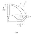
- FIG. 6 a further alternative embodiment of the flow guide element 11 is shown in a perspective view.
- This flow guide element 11 has rectangular inlet and outlet cross-sectional areas 12, 13, wherein these inlet and outlet cross-sectional areas 12, 13 can also have any desired geometry described in the preceding description part.
- the inflow cross-sectional area 12 is not arranged parallel to the outflow cross-sectional area 13.
- the outflow cross-sectional area 13 is arranged rotated by 90 ° relative to the inflow cross-sectional area 12.
- the inflow and outflow cross-sectional areas 12, 13 may also include another, any angle, in particular less than 90 °. These angles can be for example 30 °, 45 ° or 60 °.
- the inflow cross-sectional area 12 is arranged parallel to the cross-sectional area of the fresh air channel 2, whereby a right-angled flow of the flow element 11 is achieved.
- the outlet flow cross-sectional area 13 is arranged parallel to the measuring cross-sectional area 7 of the air mass sensor 5.
- the Flow element 11 via an inlet soothing zone 24 and an outlet settling zone 25.
- These calming zones 24, 25 can, as shown, be realized together on the flow element 11. In other embodiments, only a single settling zone 24 or 25 can be realized.
- the flow element 11 has a constant cross section in the flow direction, which runs parallel to the inlet cross-sectional area 12 or outlet cross-sectional area 13.
- the arrangement of a single or both calming zone (s) 24,25 may, of course, also be realized in the embodiments according to the preceding FIGURE or in other embodiments not explained in detail.
Landscapes
- Physics & Mathematics (AREA)
- Fluid Mechanics (AREA)
- General Physics & Mathematics (AREA)
- Engineering & Computer Science (AREA)
- Measuring Volume Flow (AREA)
- Chemical & Material Sciences (AREA)
- Combustion & Propulsion (AREA)
- Mechanical Engineering (AREA)
- General Engineering & Computer Science (AREA)
Applications Claiming Priority (1)
| Application Number | Priority Date | Filing Date | Title |
|---|---|---|---|
| DE200910054082 DE102009054082A1 (de) | 2009-11-20 | 2009-11-20 | Messvorrichtung, Frischluftkanal, Frischluftanlage und Strömungsführungselement |
Publications (2)
| Publication Number | Publication Date |
|---|---|
| EP2325464A2 true EP2325464A2 (fr) | 2011-05-25 |
| EP2325464A3 EP2325464A3 (fr) | 2014-01-29 |
Family
ID=43629587
Family Applications (1)
| Application Number | Title | Priority Date | Filing Date |
|---|---|---|---|
| EP10190846.5A Withdrawn EP2325464A3 (fr) | 2009-11-20 | 2010-11-11 | Dispositif de mesure, conduit d'air frais, dispositif d'air frais et élément de guidage du flux d'air |
Country Status (2)
| Country | Link |
|---|---|
| EP (1) | EP2325464A3 (fr) |
| DE (1) | DE102009054082A1 (fr) |
Cited By (2)
| Publication number | Priority date | Publication date | Assignee | Title |
|---|---|---|---|---|
| WO2014088487A1 (fr) * | 2012-12-04 | 2014-06-12 | Scania Cv Ab | Conduite à capteur de débit d'air massique |
| EP4134635A1 (fr) * | 2021-08-11 | 2023-02-15 | Sick Ag | Détermination du débit d'un fluide en écoulement |
Citations (1)
| Publication number | Priority date | Publication date | Assignee | Title |
|---|---|---|---|---|
| DE10145195A1 (de) | 2001-09-13 | 2003-04-10 | Siemens Ag | Vorrichtung zum Messen der Luftmasse in einem Ansaugkanal einer Brennkraftmaschine |
Family Cites Families (11)
| Publication number | Priority date | Publication date | Assignee | Title |
|---|---|---|---|---|
| JP2694664B2 (ja) * | 1989-03-07 | 1997-12-24 | 株式会社日立製作所 | 熱線式空気流量計及び該流量計を備えた内燃機関 |
| DE69104511T3 (de) * | 1990-02-07 | 2001-08-09 | Hitachi Ltd | Luftströmungsmengenmesser für Brennkraftmaschine. |
| JP2846207B2 (ja) * | 1992-09-17 | 1999-01-13 | 株式会社日立製作所 | 空気流量測定装置 |
| DE19815654A1 (de) * | 1998-04-08 | 1999-10-14 | Bosch Gmbh Robert | Meßvorrichtung zum Messen der Masse eines in einer Leitung strömenden Mediums |
| JP3475853B2 (ja) * | 1998-12-21 | 2003-12-10 | 三菱電機株式会社 | 流量測定装置 |
| DE10016642A1 (de) * | 2000-04-04 | 2001-10-18 | Bosch Gmbh Robert | Vorrichtung zur Bestimmung zumindest eines Parameters eines strömenden Mediums |
| JP3671393B2 (ja) * | 2001-05-24 | 2005-07-13 | 三菱電機株式会社 | 感熱式流量センサ |
| DE10154253B4 (de) * | 2001-11-05 | 2006-06-22 | Siemens Ag | Vorrichtung mit einem Luftansaugrohr und einer darin eingesteckten Luftmassensensoranordnung |
| US7036366B2 (en) * | 2004-05-25 | 2006-05-02 | Delphi Technologies, Inc. | Air flow measurement system having reduced sensitivity to flow field changes |
| DE102006024745A1 (de) * | 2006-05-26 | 2007-12-06 | Siemens Ag | Massenstromsensorvorrichtung |
| DE102007017058A1 (de) * | 2007-04-11 | 2008-10-16 | Continental Automotive Gmbh | Verfahren zur Luftmassenmessung und Luftmassensensor |
-
2009
- 2009-11-20 DE DE200910054082 patent/DE102009054082A1/de not_active Withdrawn
-
2010
- 2010-11-11 EP EP10190846.5A patent/EP2325464A3/fr not_active Withdrawn
Patent Citations (1)
| Publication number | Priority date | Publication date | Assignee | Title |
|---|---|---|---|---|
| DE10145195A1 (de) | 2001-09-13 | 2003-04-10 | Siemens Ag | Vorrichtung zum Messen der Luftmasse in einem Ansaugkanal einer Brennkraftmaschine |
Cited By (3)
| Publication number | Priority date | Publication date | Assignee | Title |
|---|---|---|---|---|
| WO2014088487A1 (fr) * | 2012-12-04 | 2014-06-12 | Scania Cv Ab | Conduite à capteur de débit d'air massique |
| US9880033B2 (en) | 2012-12-04 | 2018-01-30 | Scania Cv Ab | Air mass flow sensor pipe |
| EP4134635A1 (fr) * | 2021-08-11 | 2023-02-15 | Sick Ag | Détermination du débit d'un fluide en écoulement |
Also Published As
| Publication number | Publication date |
|---|---|
| EP2325464A3 (fr) | 2014-01-29 |
| DE102009054082A1 (de) | 2011-05-26 |
Similar Documents
| Publication | Publication Date | Title |
|---|---|---|
| DE2934137C2 (de) | Strömungsmeßanordnung zum Messen einer Strömungsmenge in einem rohrförmigen Kanal | |
| DE102008049891B4 (de) | Strömungsrichter für ein Durchflussmessgerät, insbesondere ein Ultraschallmessgerät | |
| DE102005019613B4 (de) | Luftstromratenmessvorrichtung mit Messeinheit | |
| EP3314214B1 (fr) | Débitmètre comprenant un canal de mesure et des canaux auxiliaires | |
| DE10343892A1 (de) | Durchflußreglervorrichtung | |
| EP2610457B1 (fr) | Dispositif de traitement des gaz d'échappement | |
| EP2116699A1 (fr) | Dispositif de traitement des gaz d'échappement | |
| DE102004029476A1 (de) | Strömungskonditionierungsvorrichtung | |
| EP2811268A1 (fr) | Débitmètre | |
| EP3274569B1 (fr) | Dispositif de mélange | |
| WO2016193221A1 (fr) | Mélangeur dans un système d'échappement | |
| DE3922489A1 (de) | Luftmessvorrichtung | |
| EP2714229B1 (fr) | Dispositif de filtration pour fluides très visqueux | |
| EP2325464A2 (fr) | Dispositif de mesure, conduit d'air frais, dispositif d'air frais et élément de guidage du flux d'air | |
| EP2749335B1 (fr) | Filtre à particules en deux parties | |
| DE102006038204B4 (de) | Eingangstrichter für eine Abgasbehandlungseinrichtung | |
| EP2005138B1 (fr) | Capteur pour la détection de particules dans un fluide et procédé de détection de particules dans un fluide | |
| DE102012217991A1 (de) | Düsenbaugruppe für einen Fluidinjektor und Fluidinjektor | |
| EP2381202A2 (fr) | Elément de connexion pour échangeurs de chaleur à tubes | |
| DE19518536B4 (de) | Abgasreinigungsvorrichtung zur Reinigung von Verbrennungsmotorabgasen | |
| DE102015121708B3 (de) | Statischer Mischer | |
| EP3769052B1 (fr) | Ensemble de capteurs | |
| DE2334365B2 (de) | Steuerventil | |
| DE102004055101A1 (de) | Baueinheit aus einem Strömungssensor, einem Durchlaßkanal und einem innerhalb des Durchlaßkanals angeordneten Meßkanals | |
| EP0049756A1 (fr) | Dispositif pour la mesure de pression différentielle |
Legal Events
| Date | Code | Title | Description |
|---|---|---|---|
| PUAI | Public reference made under article 153(3) epc to a published international application that has entered the european phase |
Free format text: ORIGINAL CODE: 0009012 |
|
| AK | Designated contracting states |
Kind code of ref document: A2 Designated state(s): AL AT BE BG CH CY CZ DE DK EE ES FI FR GB GR HR HU IE IS IT LI LT LU LV MC MK MT NL NO PL PT RO RS SE SI SK SM TR |
|
| AX | Request for extension of the european patent |
Extension state: BA ME |
|
| PUAL | Search report despatched |
Free format text: ORIGINAL CODE: 0009013 |
|
| AK | Designated contracting states |
Kind code of ref document: A3 Designated state(s): AL AT BE BG CH CY CZ DE DK EE ES FI FR GB GR HR HU IE IS IT LI LT LU LV MC MK MT NL NO PL PT RO RS SE SI SK SM TR |
|
| AX | Request for extension of the european patent |
Extension state: BA ME |
|
| RIC1 | Information provided on ipc code assigned before grant |
Ipc: G01F 5/00 20060101ALI20131220BHEP Ipc: G01F 1/684 20060101ALI20131220BHEP Ipc: G01F 15/00 20060101ALI20131220BHEP Ipc: F02D 41/18 20060101AFI20131220BHEP |
|
| 17P | Request for examination filed |
Effective date: 20140728 |
|
| RBV | Designated contracting states (corrected) |
Designated state(s): AL AT BE BG CH CY CZ DE DK EE ES FI FR GB GR HR HU IE IS IT LI LT LU LV MC MK MT NL NO PL PT RO RS SE SI SK SM TR |
|
| 17Q | First examination report despatched |
Effective date: 20180621 |
|
| STAA | Information on the status of an ep patent application or granted ep patent |
Free format text: STATUS: THE APPLICATION IS DEEMED TO BE WITHDRAWN |
|
| 18D | Application deemed to be withdrawn |
Effective date: 20181103 |