EP4134635A1 - Détermination du débit d'un fluide en écoulement - Google Patents
Détermination du débit d'un fluide en écoulement Download PDFInfo
- Publication number
- EP4134635A1 EP4134635A1 EP22185189.2A EP22185189A EP4134635A1 EP 4134635 A1 EP4134635 A1 EP 4134635A1 EP 22185189 A EP22185189 A EP 22185189A EP 4134635 A1 EP4134635 A1 EP 4134635A1
- Authority
- EP
- European Patent Office
- Prior art keywords
- flow
- measuring
- measuring device
- measuring point
- fluid
- Prior art date
- Legal status (The legal status is an assumption and is not a legal conclusion. Google has not performed a legal analysis and makes no representation as to the accuracy of the status listed.)
- Granted
Links
Images

Classifications
-
- G—PHYSICS
- G01—MEASURING; TESTING
- G01F—MEASURING VOLUME, VOLUME FLOW, MASS FLOW OR LIQUID LEVEL; METERING BY VOLUME
- G01F1/00—Measuring the volume flow or mass flow of fluid or fluent solid material wherein the fluid passes through a meter in a continuous flow
- G01F1/68—Measuring the volume flow or mass flow of fluid or fluent solid material wherein the fluid passes through a meter in a continuous flow by using thermal effects
- G01F1/684—Structural arrangements; Mounting of elements, e.g. in relation to fluid flow
- G01F1/6842—Structural arrangements; Mounting of elements, e.g. in relation to fluid flow with means for influencing the fluid flow
-
- G—PHYSICS
- G01—MEASURING; TESTING
- G01F—MEASURING VOLUME, VOLUME FLOW, MASS FLOW OR LIQUID LEVEL; METERING BY VOLUME
- G01F1/00—Measuring the volume flow or mass flow of fluid or fluent solid material wherein the fluid passes through a meter in a continuous flow
- G01F1/66—Measuring the volume flow or mass flow of fluid or fluent solid material wherein the fluid passes through a meter in a continuous flow by measuring frequency, phase shift or propagation time of electromagnetic or other waves, e.g. using ultrasonic flowmeters
-
- F—MECHANICAL ENGINEERING; LIGHTING; HEATING; WEAPONS; BLASTING
- F15—FLUID-PRESSURE ACTUATORS; HYDRAULICS OR PNEUMATICS IN GENERAL
- F15D—FLUID DYNAMICS, i.e. METHODS OR MEANS FOR INFLUENCING THE FLOW OF GASES OR LIQUIDS
- F15D1/00—Influencing flow of fluids
- F15D1/002—Influencing flow of fluids by influencing the boundary layer
-
- G—PHYSICS
- G01—MEASURING; TESTING
- G01F—MEASURING VOLUME, VOLUME FLOW, MASS FLOW OR LIQUID LEVEL; METERING BY VOLUME
- G01F1/00—Measuring the volume flow or mass flow of fluid or fluent solid material wherein the fluid passes through a meter in a continuous flow
- G01F1/05—Measuring the volume flow or mass flow of fluid or fluent solid material wherein the fluid passes through a meter in a continuous flow by using mechanical effects
- G01F1/34—Measuring the volume flow or mass flow of fluid or fluent solid material wherein the fluid passes through a meter in a continuous flow by using mechanical effects by measuring pressure or differential pressure
- G01F1/36—Measuring the volume flow or mass flow of fluid or fluent solid material wherein the fluid passes through a meter in a continuous flow by using mechanical effects by measuring pressure or differential pressure the pressure or differential pressure being created by the use of flow constriction
- G01F1/40—Details of construction of the flow constriction devices
- G01F1/46—Pitot tubes
-
- G—PHYSICS
- G01—MEASURING; TESTING
- G01F—MEASURING VOLUME, VOLUME FLOW, MASS FLOW OR LIQUID LEVEL; METERING BY VOLUME
- G01F1/00—Measuring the volume flow or mass flow of fluid or fluent solid material wherein the fluid passes through a meter in a continuous flow
- G01F1/68—Measuring the volume flow or mass flow of fluid or fluent solid material wherein the fluid passes through a meter in a continuous flow by using thermal effects
- G01F1/684—Structural arrangements; Mounting of elements, e.g. in relation to fluid flow
- G01F1/6847—Structural arrangements; Mounting of elements, e.g. in relation to fluid flow where sensing or heating elements are not disturbing the fluid flow, e.g. elements mounted outside the flow duct
-
- G—PHYSICS
- G01—MEASURING; TESTING
- G01F—MEASURING VOLUME, VOLUME FLOW, MASS FLOW OR LIQUID LEVEL; METERING BY VOLUME
- G01F5/00—Measuring a proportion of the volume flow
Definitions
- the invention relates to a flow measuring device for determining the flow of a fluid flowing in a line and a method for measuring the flow of a fluid flowing in a line according to the preamble of claim 1 and 15 respectively.
- figure 6 10 illustrates this on a line 100 when measuring for a point of disturbance, here in the form of a bend, as a result of which the flow of the fluid 102 is deflected and disturbed as indicated by the arrow 104 .
- the measuring point 106 is behind the point of disturbance.
- a first flow profile 108 in front of the point of disturbance is still undisturbed and symmetrical. From a selective measurement, the entire flow cross-section can be deduced without any problems. The distribution of the local mass flow density is changed in a second flow profile 110 behind the point of disturbance. Under the same assumptions as in the case of the undisturbed first flow profile 108, the conclusion from the selective measurement of the entire flow cross section would lead to a greatly deviating measurement result. A particular problem here is that the second flow profile 110 is not known and also not reproducible. The deviation between the flow profiles 108, 110 therefore generates a measurement error, with measurement deviations of ⁇ 50% and more being entirely to be expected.
- Such a point-measuring method is thermal or calorimetric flow measurement, which is based on the different heat transport of a flowing fluid based on the flow rate.
- heating elements and temperature sensors are arranged in the flow.
- the various known variants differ in the type of probes and their arrangement as well as in the measuring method.
- a thin wire is used in hot wire anemometry.
- the method is suitable for rapid local flow fluctuations at atmospheric pressure, but is very susceptible to fouling.
- Alternative designs of the probes in thin-film technology ensure greater robustness.
- Metallic probes are also known, but significantly increase the response time.
- the temperature on the heating element is also determined using an additional temperature sensor that is integrated or arranged there.
- the mass flow is a function of the heating power required to maintain a required temperature difference between the heating element and the temperature sensor.
- the traditional substitute for a long, straight run-in is to use a flow guide.
- Different flow phenomena can be distinguished.
- the flow can exhibit a twist and, last but not least, show a behavior that changes over time, which under Circumstances, depending on the fluid, flow speed and obstacle, turns into turbulence.
- the flow guiding element is designed as a flow converter or flow straightener; a narrowing of the profile is also possible.
- a disadvantage of conventional flow guidance elements is their considerable pressure loss, to which the effect on the flow is coupled. A loss of pressure must ultimately be compensated at some point and thus consumes energy continuously. In addition, with flow guiding elements according to the state of the art, a certain calming distance for the flow in front of the measuring point is required.
- the DE 10 2006 047 526 A1 discloses a flow straightener with a plurality of essentially rectangular fins in a star-shaped arrangement, the fins having through-holes.
- another flow straightener is also presented for an ultrasonic measurement.
- the geometry is more complex, with several webs swept alternately in the direction of flow and against the direction of flow.
- a bottleneck is created.
- the EP 1 775 560 A2 shows a further variant of a flow straightener for an ultrasonic flow measuring device. First and second rectifying means are twisted in opposite directions with the aim of thereby eliminating turbulence. All of these flow straighteners are designed for ultrasonic measurements, where the problem of a punctiform measurement does not arise because of the ultrasonic paths. The previously discussed disadvantages of pressure drop are not addressed and not solved.
- a flow measuring device for determining the flow rate of a fluid flowing in a line and a method for flow rate measurement of a fluid flowing in a line of claim 1 and 15, respectively.
- the quantity measured is often the mass flow.
- mass flow, flow velocity, volume flow or flow rate correspond to one another or can be converted into one another, so that the "flow" is representative of these typical variables that are measured with a flow measuring device.
- the portion of the line that is measured is often replaced by the flow measurement device that is built into the line. This difference will not be discussed further and the term line will continue to be used for the sake of simplicity.
- a measuring element arranged at a measuring point in the line selectively detects a measured variable of the flowing fluid.
- a control and evaluation unit uses the measured variable of the measuring element to determine the flow rate sought.
- Measuring point or selective detection means that measurements are only taken at one point or, in practical terms, only on a very small area. So only a very small local section of the flow cross section is recorded, in the measurement itself there is no averaging over the flow profile.
- ultrasonic paths would not be punctiform or 0-dimensional, but at least 1-dimensional, with multiple ultrasonic paths often being used in order to better map the flow cross-section.
- a flow guide element is arranged upstream of the measuring point with respect to the flow direction of the fluid.
- a flow guiding element as discussed in the introduction, would ensure a reproducible and uniform flow and create conditions as it were in a fictitious installation situation, as if the flow measuring device were preceded by a longer, straight and undisturbed inlet section.
- the flow guidance element has a different function, as explained immediately.
- the invention is based on the basic idea of providing a measurement situation at the measurement point that is representative of the flow profile.
- the flow guidance element is designed in such a way that it feeds portions of the flow to the measuring point that are also representative of the rest of the flow.
- the flow as a whole is left as unchanged as possible, a calming down or the like of the entire flow is expressly not sought and not achieved.
- the flow guiding element acts as a kind of flow tap, with which said representative part of the flow is cut out and guided to the measuring point. A local mass flow density can therefore be measured at the measuring point as a representative of the entire flow profile.
- the invention has the advantage that a significantly reduced sensitivity to even unfavorable inlet conditions is achieved.
- control and evaluation unit can be designed to apply a constant current to the at least one heating element, to control its heating output itself or its heating output in such a way that the temperature on the heating element differs from the temperature information of the at least a temperature sensor deviates.
- CCA method Constant Current Anemometry
- CPA method Constant Power Anenometry
- CTA method Constant Temperature Anemometry
- the at least one heating element and/or the at least one temperature sensor is particularly preferably produced using thin-film technology. This results in inexpensive and at the same time reliable and robust components that enable reproducible heating or temperature measurement.
- the measuring element has a pressure measuring element.
- a flow measurement based on a point measurement at a measurement point.
- the flow measuring device is designed as a pitot tube or a dynamic pressure probe.
- the measuring point is preferably arranged within the flow guidance element or directly follows the flow guidance element. According to the invention, in contrast to conventional flow converters or flow rectifiers, no downstream contact section is required, or at least only an extremely short one.
- the flow guiding element preferably has at least one opening in order to have an unaffected portion of the fluid which is complementary to the representative portion to let through. According to the invention, only a representative portion of the flow is supplied to the measuring point. The rest of the flow preferably remains unaffected and simply flows through the at least one opening. Influencing the flow or calming the flow overall is not intended at all. By allowing an unaffected portion of the fluid to pass through, the pressure drop can be kept particularly low.
- the flow guidance element preferably has a plurality of support elements angularly offset from the arms, in particular one support element in each case in the middle between two arms.
- the support elements serve to mechanically stabilize the flow guidance element in the flow. They should take up as little flow cross-section as possible while still being sufficiently strong. With a central arrangement between two arms, the flow remains largely unchanged, as desired. For example, in a cross arrangement of the arms, the supports form another cross that is twisted by 45°. In contrast to the arms, the supports do not have any guide slots or guide channels, they do not contribute to tapping off the representative portion of the flow.
- the example of a point measurement considered in more detail here is thermal or calorimetric flow measurement.
- Another alternative mentioned by way of example is a flow measurement based on the pressure or pressure drop.
- the thermal flow measurement has already been briefly presented in the introduction; in this respect, the flow measurement device 10 can be designed as in the prior art.
- the measuring element 20 has a substructure with at least one heating element and at least one temperature sensor, which are preferably produced using thin-film technology.
- the control and evaluation unit 22 is connected to the at least one heating element and the at least one temperature sensor in order to evaluate the temperature measurements, to control the heating output and to determine a flow rate or a flow rate of the fluid 14 .
- any known method can be used to measure the flow rate.
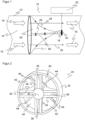
- the flow guide element 24 is surrounded by a cylindrical frame 30 whose outside diameter corresponds to the inside diameter of the line 12 .
- a central blocking element 32 is provided which does not allow any fluid 14 to flow through on the longitudinal central axis of the line 12.
- Extending radially outwardly from the central blocking member are a plurality of arms 34, in the preferred embodiment illustrated four arms 34 in one Cross with right angles between the arms 34.
- the arms 34 have guide slots 36 towards the front, through which the fluid 14 can flow into the arms 34.
- the guide channels 38 open into a central guide channel 40 which ends at the measuring point 18 .
- the front side of the flow guide element 24 is preferably symmetrical, with a centrally arranged central blocking element 32 and arms 34 of a regular cross of equal length in this cross-sectional plane.
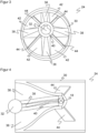
- the measuring point 18 is off-center, without loss of generality due to a possible upward rotation of the line 12, so that the measuring element 20 is more easily accessible.
- the central guide channel 40 thus does not remain on the longitudinal central axis, but deviates upwards towards the measuring point 18 . Accordingly, the upper of the arms 34 becomes shorter and the lower of the arms 34 becomes longer on the upright diameter along the flow guide member 24 . In the two arms 34 arranged transversely thereto, the guide channels 38 pull upwards, as in FIG figure 3 to recognize.
- the asymmetry described and illustrated is only one conceivable embodiment.
- the measuring point 18 can be arranged in the center, that is to say it can lie on the longitudinal central axis of the line 12 .
- the measuring element 20 must be arranged and connected accordingly in the middle.
- the flow guidance element 24 has openings 42 through which the fluid 14 can flow unaffected. As in the figures 2 and 3 As can be seen, the combined area of these openings 42 accounts for a large proportion of the cross-sectional area of the conduit 12. A balance must be found between a sufficiently representative proportion of the flow, which is tapped off through the guide slots 36 in the arms 34, and the lowest possible pressure loss through large openings 42. Supporting elements 44 are arranged in the openings for improved mechanical stability. With sufficient strength, they also take up as little cross-sectional area as possible. A central location within the openings 42 has the least influence on the flow. The support elements 44 thus also form a cross in the preferred illustrated embodiment, like the arms 34 and rotated by 45°.
- the flow guide element 24 uses the guide slots 36 to pick up partial cross-sections of the flow profile and guides these partial flows to the measuring point 18 by means of the guide channels 38 adjoining the guide slots 36 and the central guide channel 40.
- the geometry of the guide slots 36 is selected such that the to the measuring point 18 guided partial flow is representative of the total flow cross-section.
- the guide slots 36 extend radially over the entire line 12, and a plurality of radial partial flows are tapped off in the circumferential direction via the plurality of arms 34. Thus, a good averaging takes place.
- the guide slots 36 do not become too large. This would lead to the flow at the measuring point 18 accelerating to an undesired extent.
- a large pressure drop in the flow behind the flow guide element 24 would be caused overall, since the openings 42 through which the fluid 14 can flow unhindered then take up too little area compared to the guide slots 36 .
- eccentric measuring point 18 its central arrangement is also conceivable. This supports an undisturbed flow past of the flow components flowing through the openings 42 .
- the disruptive effect is also limited in the case of an eccentric measuring point 18, at least as long as the front side remains symmetrical and the offset from the center relative to the radius of the line cross section remains small.
Landscapes
- Physics & Mathematics (AREA)
- Fluid Mechanics (AREA)
- General Physics & Mathematics (AREA)
- Engineering & Computer Science (AREA)
- Electromagnetism (AREA)
- Mechanical Engineering (AREA)
- General Engineering & Computer Science (AREA)
- Measuring Volume Flow (AREA)
Applications Claiming Priority (1)
| Application Number | Priority Date | Filing Date | Title |
|---|---|---|---|
| DE102021120883.1A DE102021120883A1 (de) | 2021-08-11 | 2021-08-11 | Bestimmung des Durchflusses eines strömenden Fluids |
Publications (3)
| Publication Number | Publication Date |
|---|---|
| EP4134635A1 true EP4134635A1 (fr) | 2023-02-15 |
| EP4134635B1 EP4134635B1 (fr) | 2024-01-24 |
| EP4134635C0 EP4134635C0 (fr) | 2024-01-24 |
Family
ID=82608095
Family Applications (1)
| Application Number | Title | Priority Date | Filing Date |
|---|---|---|---|
| EP22185189.2A Active EP4134635B1 (fr) | 2021-08-11 | 2022-07-15 | Détermination du débit d'un fluide en écoulement |
Country Status (4)
| Country | Link |
|---|---|
| US (1) | US20230051345A1 (fr) |
| EP (1) | EP4134635B1 (fr) |
| JP (1) | JP2023026329A (fr) |
| DE (1) | DE102021120883A1 (fr) |
Citations (9)
| Publication number | Priority date | Publication date | Assignee | Title |
|---|---|---|---|---|
| JPH05340779A (ja) * | 1992-06-11 | 1993-12-21 | Hitachi Ltd | 空気流量測定装置及びこれを用いたエンジンの燃料制御システム |
| JPH063172A (ja) * | 1992-06-17 | 1994-01-11 | Hitachi Ltd | 発熱抵抗式空気流量計 |
| EP0588626A2 (fr) * | 1992-09-17 | 1994-03-23 | Hitachi, Ltd. | Dispositif de mesure de débit d'air |
| US20050039809A1 (en) | 2003-08-21 | 2005-02-24 | Speldrich Jamie W. | Flow sensor with integrated delta P flow restrictor |
| EP1775560A2 (fr) | 2005-10-14 | 2007-04-18 | Kamstrup A/S | Ecoulement plus direct d'un compteur d'écoulement ultrasonique |
| DE102006047526A1 (de) | 2006-10-07 | 2008-04-10 | Sick Engineering Gmbh | Strömungsgleichrichter |
| EP2325464A2 (fr) * | 2009-11-20 | 2011-05-25 | MAHLE International GmbH | Dispositif de mesure, conduit d'air frais, dispositif d'air frais et élément de guidage du flux d'air |
| DE102008049891B4 (de) | 2008-10-02 | 2012-12-06 | Hydrometer Gmbh | Strömungsrichter für ein Durchflussmessgerät, insbesondere ein Ultraschallmessgerät |
| EP2607718B1 (fr) | 2011-12-19 | 2014-02-26 | SICK Engineering GmbH | Tranquilliseur de débit |
Family Cites Families (12)
| Publication number | Priority date | Publication date | Assignee | Title |
|---|---|---|---|---|
| JP2921150B2 (ja) * | 1990-04-02 | 1999-07-19 | 株式会社日立製作所 | 熱式空気流量計 |
| JPH11211525A (ja) * | 1998-01-30 | 1999-08-06 | Tokyo Gas Co Ltd | フローセンサを利用した流量計 |
| US6119730A (en) * | 1998-12-21 | 2000-09-19 | Mcmillan Company | Precision laminar flow element for use in thermal mass flow sensors and flow controllers |
| DE10016642A1 (de) | 2000-04-04 | 2001-10-18 | Bosch Gmbh Robert | Vorrichtung zur Bestimmung zumindest eines Parameters eines strömenden Mediums |
| JP2003315127A (ja) * | 2002-04-17 | 2003-11-06 | Kazumasa Onishi | 熱式流量計 |
| WO2004010087A2 (fr) * | 2002-07-19 | 2004-01-29 | Celerity Group, Inc | Debitmetre |
| JP4826140B2 (ja) * | 2005-05-30 | 2011-11-30 | 株式会社デンソー | 流量測定装置 |
| DE102006024745A1 (de) | 2006-05-26 | 2007-12-06 | Siemens Ag | Massenstromsensorvorrichtung |
| DE102007017058A1 (de) | 2007-04-11 | 2008-10-16 | Continental Automotive Gmbh | Verfahren zur Luftmassenmessung und Luftmassensensor |
| HU229884B1 (hu) * | 2008-11-17 | 2014-11-28 | Piston Kft | Légzésdiagnosztikai áramlásmérõ eszköz |
| US8549908B2 (en) * | 2010-06-17 | 2013-10-08 | Los Robles Advertising, Inc. | Thermal anemometer flow meter for the measurement of wet gas flow |
| JP5728841B2 (ja) * | 2010-07-26 | 2015-06-03 | オムロン株式会社 | 流量測定用構造体および流量測定装置 |
-
2021
- 2021-08-11 DE DE102021120883.1A patent/DE102021120883A1/de not_active Withdrawn
-
2022
- 2022-07-05 JP JP2022108188A patent/JP2023026329A/ja active Pending
- 2022-07-15 EP EP22185189.2A patent/EP4134635B1/fr active Active
- 2022-08-10 US US17/884,779 patent/US20230051345A1/en not_active Abandoned
Patent Citations (9)
| Publication number | Priority date | Publication date | Assignee | Title |
|---|---|---|---|---|
| JPH05340779A (ja) * | 1992-06-11 | 1993-12-21 | Hitachi Ltd | 空気流量測定装置及びこれを用いたエンジンの燃料制御システム |
| JPH063172A (ja) * | 1992-06-17 | 1994-01-11 | Hitachi Ltd | 発熱抵抗式空気流量計 |
| EP0588626A2 (fr) * | 1992-09-17 | 1994-03-23 | Hitachi, Ltd. | Dispositif de mesure de débit d'air |
| US20050039809A1 (en) | 2003-08-21 | 2005-02-24 | Speldrich Jamie W. | Flow sensor with integrated delta P flow restrictor |
| EP1775560A2 (fr) | 2005-10-14 | 2007-04-18 | Kamstrup A/S | Ecoulement plus direct d'un compteur d'écoulement ultrasonique |
| DE102006047526A1 (de) | 2006-10-07 | 2008-04-10 | Sick Engineering Gmbh | Strömungsgleichrichter |
| DE102008049891B4 (de) | 2008-10-02 | 2012-12-06 | Hydrometer Gmbh | Strömungsrichter für ein Durchflussmessgerät, insbesondere ein Ultraschallmessgerät |
| EP2325464A2 (fr) * | 2009-11-20 | 2011-05-25 | MAHLE International GmbH | Dispositif de mesure, conduit d'air frais, dispositif d'air frais et élément de guidage du flux d'air |
| EP2607718B1 (fr) | 2011-12-19 | 2014-02-26 | SICK Engineering GmbH | Tranquilliseur de débit |
Also Published As
| Publication number | Publication date |
|---|---|
| JP2023026329A (ja) | 2023-02-24 |
| DE102021120883A1 (de) | 2023-02-16 |
| EP4134635B1 (fr) | 2024-01-24 |
| EP4134635C0 (fr) | 2024-01-24 |
| US20230051345A1 (en) | 2023-02-16 |
Similar Documents
| Publication | Publication Date | Title |
|---|---|---|
| DE19852015B4 (de) | Flussratensensor | |
| EP2172657B1 (fr) | Guide d'écoulement pour un appareil de mesure du débit, notamment un appareil de mesure à ultrasons | |
| EP2565593B1 (fr) | Compteur à ultrasons | |
| DE2934137C2 (de) | Strömungsmeßanordnung zum Messen einer Strömungsmenge in einem rohrförmigen Kanal | |
| DE2938801C2 (de) | Vorrichtung zum Messen der Geschwindigkeit einer Strömung | |
| EP3222978B1 (fr) | Appareil de mesure de débit doté d'une reconnaissance d'erreurs | |
| DE2204269B2 (de) | Länglicher Wirbelkörper zum Messen der Strömungsgeschwindigkeit eines Strömungsmittels in einer Leitung | |
| EP2811268A1 (fr) | Débitmètre | |
| DE102004019521B4 (de) | Durchflussmessgerät | |
| DE2212746B2 (de) | Stroemungsrichter | |
| DE3336911A1 (de) | Vorrichtung zum messen des volumenstroms eines gases in einem kanal | |
| DE2164180C3 (de) | Strömungsmesser | |
| DE102008042807B4 (de) | Vorrichtung zur Bestimmung eines Parameters eines strömenden fluiden Mediums | |
| WO2001018498A9 (fr) | Dispositif pour la mesure d'au moins un parametre d'un milieu en ecoulement dans une conduite | |
| DE102010062892A1 (de) | Strömungsgitter zum Einsatz in einem Strömungsrohr eines strömenden fluiden Mediums | |
| DE3002712C2 (fr) | ||
| EP4134635A1 (fr) | Détermination du débit d'un fluide en écoulement | |
| DE202021104287U1 (de) | Bestimmung des Durchflusses eines strömenden Fluids | |
| DE19848109B4 (de) | Durchflussmengenfühler | |
| DE102007060046A1 (de) | Sensoranordnung zur Bestimmung eines Parameters eines strömenden fluiden Mediums | |
| EP1818665A2 (fr) | Détecteur de particule | |
| EP3748309B1 (fr) | Débitmètre à ultrasons, utilisation d'un débitmètre à ultrasons dans un organe d'arrêt et organe d'arrêt | |
| EP3695167B1 (fr) | Installation de combustion d'une centrale | |
| DE102006047526A1 (de) | Strömungsgleichrichter | |
| DE2921550C2 (de) | Sonde für eine Strömungsgeschwindigkeitsmeßeinrichtung |
Legal Events
| Date | Code | Title | Description |
|---|---|---|---|
| PUAI | Public reference made under article 153(3) epc to a published international application that has entered the european phase |
Free format text: ORIGINAL CODE: 0009012 |
|
| STAA | Information on the status of an ep patent application or granted ep patent |
Free format text: STATUS: THE APPLICATION HAS BEEN PUBLISHED |
|
| AK | Designated contracting states |
Kind code of ref document: A1 Designated state(s): AL AT BE BG CH CY CZ DE DK EE ES FI FR GB GR HR HU IE IS IT LI LT LU LV MC MK MT NL NO PL PT RO RS SE SI SK SM TR |
|
| STAA | Information on the status of an ep patent application or granted ep patent |
Free format text: STATUS: REQUEST FOR EXAMINATION WAS MADE |
|
| 17P | Request for examination filed |
Effective date: 20230502 |
|
| RBV | Designated contracting states (corrected) |
Designated state(s): AL AT BE BG CH CY CZ DE DK EE ES FI FR GB GR HR HU IE IS IT LI LT LU LV MC MK MT NL NO PL PT RO RS SE SI SK SM TR |
|
| GRAP | Despatch of communication of intention to grant a patent |
Free format text: ORIGINAL CODE: EPIDOSNIGR1 |
|
| STAA | Information on the status of an ep patent application or granted ep patent |
Free format text: STATUS: GRANT OF PATENT IS INTENDED |
|
| INTG | Intention to grant announced |
Effective date: 20230926 |
|
| GRAS | Grant fee paid |
Free format text: ORIGINAL CODE: EPIDOSNIGR3 |
|
| GRAA | (expected) grant |
Free format text: ORIGINAL CODE: 0009210 |
|
| STAA | Information on the status of an ep patent application or granted ep patent |
Free format text: STATUS: THE PATENT HAS BEEN GRANTED |
|
| AK | Designated contracting states |
Kind code of ref document: B1 Designated state(s): AL AT BE BG CH CY CZ DE DK EE ES FI FR GB GR HR HU IE IS IT LI LT LU LV MC MK MT NL NO PL PT RO RS SE SI SK SM TR |
|
| REG | Reference to a national code |
Ref country code: GB Ref legal event code: FG4D Free format text: NOT ENGLISH |
|
| REG | Reference to a national code |
Ref country code: CH Ref legal event code: EP |
|
| REG | Reference to a national code |
Ref country code: DE Ref legal event code: R096 Ref document number: 502022000423 Country of ref document: DE |
|
| REG | Reference to a national code |
Ref country code: IE Ref legal event code: FG4D Free format text: LANGUAGE OF EP DOCUMENT: GERMAN |
|
| U01 | Request for unitary effect filed |
Effective date: 20240131 |
|
| U07 | Unitary effect registered |
Designated state(s): AT BE BG DE DK EE FI FR IT LT LU LV MT NL PT SE SI Effective date: 20240209 |
|
| PG25 | Lapsed in a contracting state [announced via postgrant information from national office to epo] |
Ref country code: IS Free format text: LAPSE BECAUSE OF FAILURE TO SUBMIT A TRANSLATION OF THE DESCRIPTION OR TO PAY THE FEE WITHIN THE PRESCRIBED TIME-LIMIT Effective date: 20240524 |
|
| PG25 | Lapsed in a contracting state [announced via postgrant information from national office to epo] |
Ref country code: GR Free format text: LAPSE BECAUSE OF FAILURE TO SUBMIT A TRANSLATION OF THE DESCRIPTION OR TO PAY THE FEE WITHIN THE PRESCRIBED TIME-LIMIT Effective date: 20240425 |
|
| PG25 | Lapsed in a contracting state [announced via postgrant information from national office to epo] |
Ref country code: RS Free format text: LAPSE BECAUSE OF FAILURE TO SUBMIT A TRANSLATION OF THE DESCRIPTION OR TO PAY THE FEE WITHIN THE PRESCRIBED TIME-LIMIT Effective date: 20240424 Ref country code: HR Free format text: LAPSE BECAUSE OF FAILURE TO SUBMIT A TRANSLATION OF THE DESCRIPTION OR TO PAY THE FEE WITHIN THE PRESCRIBED TIME-LIMIT Effective date: 20240124 |
|
| PG25 | Lapsed in a contracting state [announced via postgrant information from national office to epo] |
Ref country code: ES Free format text: LAPSE BECAUSE OF FAILURE TO SUBMIT A TRANSLATION OF THE DESCRIPTION OR TO PAY THE FEE WITHIN THE PRESCRIBED TIME-LIMIT Effective date: 20240124 |
|
| PG25 | Lapsed in a contracting state [announced via postgrant information from national office to epo] |
Ref country code: RS Free format text: LAPSE BECAUSE OF FAILURE TO SUBMIT A TRANSLATION OF THE DESCRIPTION OR TO PAY THE FEE WITHIN THE PRESCRIBED TIME-LIMIT Effective date: 20240424 Ref country code: NO Free format text: LAPSE BECAUSE OF FAILURE TO SUBMIT A TRANSLATION OF THE DESCRIPTION OR TO PAY THE FEE WITHIN THE PRESCRIBED TIME-LIMIT Effective date: 20240424 Ref country code: IS Free format text: LAPSE BECAUSE OF FAILURE TO SUBMIT A TRANSLATION OF THE DESCRIPTION OR TO PAY THE FEE WITHIN THE PRESCRIBED TIME-LIMIT Effective date: 20240524 Ref country code: HR Free format text: LAPSE BECAUSE OF FAILURE TO SUBMIT A TRANSLATION OF THE DESCRIPTION OR TO PAY THE FEE WITHIN THE PRESCRIBED TIME-LIMIT Effective date: 20240124 Ref country code: GR Free format text: LAPSE BECAUSE OF FAILURE TO SUBMIT A TRANSLATION OF THE DESCRIPTION OR TO PAY THE FEE WITHIN THE PRESCRIBED TIME-LIMIT Effective date: 20240425 Ref country code: ES Free format text: LAPSE BECAUSE OF FAILURE TO SUBMIT A TRANSLATION OF THE DESCRIPTION OR TO PAY THE FEE WITHIN THE PRESCRIBED TIME-LIMIT Effective date: 20240124 |
|
| PG25 | Lapsed in a contracting state [announced via postgrant information from national office to epo] |
Ref country code: PL Free format text: LAPSE BECAUSE OF FAILURE TO SUBMIT A TRANSLATION OF THE DESCRIPTION OR TO PAY THE FEE WITHIN THE PRESCRIBED TIME-LIMIT Effective date: 20240124 |
|
| U20 | Renewal fee for the european patent with unitary effect paid |
Year of fee payment: 3 Effective date: 20240717 |
|
| PG25 | Lapsed in a contracting state [announced via postgrant information from national office to epo] |
Ref country code: PL Free format text: LAPSE BECAUSE OF FAILURE TO SUBMIT A TRANSLATION OF THE DESCRIPTION OR TO PAY THE FEE WITHIN THE PRESCRIBED TIME-LIMIT Effective date: 20240124 |
|
| PG25 | Lapsed in a contracting state [announced via postgrant information from national office to epo] |
Ref country code: SM Free format text: LAPSE BECAUSE OF FAILURE TO SUBMIT A TRANSLATION OF THE DESCRIPTION OR TO PAY THE FEE WITHIN THE PRESCRIBED TIME-LIMIT Effective date: 20240124 |
|
| PG25 | Lapsed in a contracting state [announced via postgrant information from national office to epo] |
Ref country code: CZ Free format text: LAPSE BECAUSE OF FAILURE TO SUBMIT A TRANSLATION OF THE DESCRIPTION OR TO PAY THE FEE WITHIN THE PRESCRIBED TIME-LIMIT Effective date: 20240124 |
|
| REG | Reference to a national code |
Ref country code: DE Ref legal event code: R097 Ref document number: 502022000423 Country of ref document: DE |
|
| PG25 | Lapsed in a contracting state [announced via postgrant information from national office to epo] |
Ref country code: SK Free format text: LAPSE BECAUSE OF FAILURE TO SUBMIT A TRANSLATION OF THE DESCRIPTION OR TO PAY THE FEE WITHIN THE PRESCRIBED TIME-LIMIT Effective date: 20240124 |
|
| PG25 | Lapsed in a contracting state [announced via postgrant information from national office to epo] |
Ref country code: SM Free format text: LAPSE BECAUSE OF FAILURE TO SUBMIT A TRANSLATION OF THE DESCRIPTION OR TO PAY THE FEE WITHIN THE PRESCRIBED TIME-LIMIT Effective date: 20240124 Ref country code: SK Free format text: LAPSE BECAUSE OF FAILURE TO SUBMIT A TRANSLATION OF THE DESCRIPTION OR TO PAY THE FEE WITHIN THE PRESCRIBED TIME-LIMIT Effective date: 20240124 Ref country code: CZ Free format text: LAPSE BECAUSE OF FAILURE TO SUBMIT A TRANSLATION OF THE DESCRIPTION OR TO PAY THE FEE WITHIN THE PRESCRIBED TIME-LIMIT Effective date: 20240124 |
|
| PLBE | No opposition filed within time limit |
Free format text: ORIGINAL CODE: 0009261 |
|
| STAA | Information on the status of an ep patent application or granted ep patent |
Free format text: STATUS: NO OPPOSITION FILED WITHIN TIME LIMIT |
|
| 26N | No opposition filed |
Effective date: 20241025 |
|
| PG25 | Lapsed in a contracting state [announced via postgrant information from national office to epo] |
Ref country code: MC Free format text: LAPSE BECAUSE OF FAILURE TO SUBMIT A TRANSLATION OF THE DESCRIPTION OR TO PAY THE FEE WITHIN THE PRESCRIBED TIME-LIMIT Effective date: 20240124 |
|
| PG25 | Lapsed in a contracting state [announced via postgrant information from national office to epo] |
Ref country code: IE Free format text: LAPSE BECAUSE OF NON-PAYMENT OF DUE FEES Effective date: 20240715 |
|
| U20 | Renewal fee for the european patent with unitary effect paid |
Year of fee payment: 4 Effective date: 20250729 |
|
| PG25 | Lapsed in a contracting state [announced via postgrant information from national office to epo] |
Ref country code: RO Free format text: LAPSE BECAUSE OF FAILURE TO SUBMIT A TRANSLATION OF THE DESCRIPTION OR TO PAY THE FEE WITHIN THE PRESCRIBED TIME-LIMIT Effective date: 20240124 |
|
| PG25 | Lapsed in a contracting state [announced via postgrant information from national office to epo] |
Ref country code: CY Free format text: LAPSE BECAUSE OF FAILURE TO SUBMIT A TRANSLATION OF THE DESCRIPTION OR TO PAY THE FEE WITHIN THE PRESCRIBED TIME-LIMIT; INVALID AB INITIO Effective date: 20220715 |
|
| REG | Reference to a national code |
Ref country code: CH Ref legal event code: H13 Free format text: ST27 STATUS EVENT CODE: U-0-0-H10-H13 (AS PROVIDED BY THE NATIONAL OFFICE) Effective date: 20260224 |
|
| PG25 | Lapsed in a contracting state [announced via postgrant information from national office to epo] |
Ref country code: HU Free format text: LAPSE BECAUSE OF FAILURE TO SUBMIT A TRANSLATION OF THE DESCRIPTION OR TO PAY THE FEE WITHIN THE PRESCRIBED TIME-LIMIT; INVALID AB INITIO Effective date: 20220715 |
|
| PG25 | Lapsed in a contracting state [announced via postgrant information from national office to epo] |
Ref country code: CH Free format text: LAPSE BECAUSE OF NON-PAYMENT OF DUE FEES Effective date: 20250731 |