EP2323024A2 - Mehrkanaliger Berührungsbildschirm - Google Patents
Mehrkanaliger Berührungsbildschirm Download PDFInfo
- Publication number
- EP2323024A2 EP2323024A2 EP10151476A EP10151476A EP2323024A2 EP 2323024 A2 EP2323024 A2 EP 2323024A2 EP 10151476 A EP10151476 A EP 10151476A EP 10151476 A EP10151476 A EP 10151476A EP 2323024 A2 EP2323024 A2 EP 2323024A2
- Authority
- EP
- European Patent Office
- Prior art keywords
- sensing
- driving
- electrode
- electrodes
- lines
- Prior art date
- Legal status (The legal status is an assumption and is not a legal conclusion. Google has not performed a legal analysis and makes no representation as to the accuracy of the status listed.)
- Granted
Links
- 239000011159 matrix material Substances 0.000 claims abstract description 76
- 239000004020 conductor Substances 0.000 claims description 9
- 239000003990 capacitor Substances 0.000 claims description 8
- 230000000295 complement effect Effects 0.000 claims description 4
- 229910003460 diamond Inorganic materials 0.000 claims description 4
- 239000010432 diamond Substances 0.000 claims description 4
- 239000010410 layer Substances 0.000 description 17
- 238000010586 diagram Methods 0.000 description 7
- 230000004048 modification Effects 0.000 description 4
- 238000012986 modification Methods 0.000 description 4
- 230000001360 synchronised effect Effects 0.000 description 4
- 239000012811 non-conductive material Substances 0.000 description 3
- 230000005540 biological transmission Effects 0.000 description 1
- 230000007812 deficiency Effects 0.000 description 1
- 238000001514 detection method Methods 0.000 description 1
- 239000004973 liquid crystal related substance Substances 0.000 description 1
- 239000000463 material Substances 0.000 description 1
- 239000002356 single layer Substances 0.000 description 1
- 239000000758 substrate Substances 0.000 description 1
Images


Classifications
-
- G—PHYSICS
- G06—COMPUTING; CALCULATING OR COUNTING
- G06F—ELECTRIC DIGITAL DATA PROCESSING
- G06F3/00—Input arrangements for transferring data to be processed into a form capable of being handled by the computer; Output arrangements for transferring data from processing unit to output unit, e.g. interface arrangements
- G06F3/01—Input arrangements or combined input and output arrangements for interaction between user and computer
- G06F3/03—Arrangements for converting the position or the displacement of a member into a coded form
- G06F3/041—Digitisers, e.g. for touch screens or touch pads, characterised by the transducing means
- G06F3/044—Digitisers, e.g. for touch screens or touch pads, characterised by the transducing means by capacitive means
- G06F3/0446—Digitisers, e.g. for touch screens or touch pads, characterised by the transducing means by capacitive means using a grid-like structure of electrodes in at least two directions, e.g. using row and column electrodes
Definitions
- the present invention relates generally to a touch panel, and more particularly to a touch panel that utilizes multi-channel driving and multi-channel sensing to reduce RC loading of driving electrodes and/or sensing electrodes.
- Touch sensing technology capable of providing a natural interface between an electronic system and user has found widespread applications in a variety of fields, for example, in mobile phones, personal digital assistants (PDAs), automatic teller machines (ATMs), game machines, medical devices, liquid crystal display (LCD) devices, light emitting diode (LED) devices, plasma display panel (PDP) devices, computing devices, and the like, where a user may input desired information and/or operate the electronic system through a touch sensing device associated with the electronic system.
- a touch sensing device typically includes a controller, a sensing circuit having a plurality of touch sensors and a network of control lines electrically connecting the plurality of touch sensors to the controller, and a touch panel associated with the plurality of touch sensors.
- touch sensing devices There are different types of touch sensing devices available for detection of a touch location.
- One is a resistive-type touch sensing device that includes two layers of transparent conductive material, such as a transparent conductive oxide, separated by a gap. When touched with sufficient force, one of the conductive layers flexes to make contact with the other conductive layer. The location of the contact point is detectable by a controller that senses the change in resistance at the contact point. In response, the controller performs a function, if any, associated with the contact point.
- the capacitive-type touch sensing device can be classified into two types: an analog capacitive sensing device, which uses a contiguous resistive layer, and a projected capacitive sensing device, which uses patterned conductive layers (electrodes).
- the touch sensor employs a series of patterned electrodes that are driven with a signal from a controller.
- a location of the contact point can be derived from currents flowing through one or more corresponding electrodes toward the touch point responsive to the touch with sensing the capacitance induced by a user's finger.
- a finger touch to the sensor provides a capacitive couple from the conductive layer to the body.
- the location of the contact point is detectable by a controller that measures a change in a capacitively coupled electrical signal at the touch location. Accordingly, the controller performs a function, if any, associated with the touch location.
- Fig. 11 and Fig. 12 show a conventional touch device 10 having 5 driving electrode strips 11, 5 ⁇ 5 sensing electrodes 12 arranged in a 5 ⁇ 5 matrix, 5 driving lines X1-X5, arranged alone the row direction, and 5 sensing lines Y1-Y5, arranged alone the column direction.
- Each driving electrode strip 11 is electrically connected to a corresponding driving line X1-X5.
- Each sensing electrode 12 in a column is electrically connected to each other by a corresponding sensing line Y1-Y5.
- the driving signals 18 and the sensing signals 17 of sensing electrodes in distal areas are substantially deformed, comparing to a driving signal 16 applied to a driving electrode strip, due to the RC loading of the driving electrodes 11 and/or sensing electrodes 12.
- the deformation of the sensing signals may result in poor performance of the touch device.
- the present invention in one aspect, relates to a multi-channel touch panel.
- the multi-channel touch panel includes a plurality of driving electrodes spatial-separately arranged in the form of a matrix, and a plurality of sensing electrodes associated with the plurality of driving electrodes such that each sensing electrode is surrounded by a corresponding driving electrode, wherein the plurality of driving electrodes and the plurality of sensing electrodes define an electrode matrix having N rows and M columns, each of N and M being a positive integer.
- each of the plurality of sensing electrodes and the corresponding one of the plurality of driving electrodes are electrically insulated from one another.
- Each of the plurality of sensing electrodes and the corresponding one of the plurality of driving electrodes define a sensing capacitor. Additionally, each of the plurality of sensing electrodes and the corresponding one of the plurality of driving electrodes that surrounds the sensing electrode are spatially separated from one another.
- each of the plurality of driving electrodes is formed to have a body portion and a bridge electrically connected the body portion to a corresponding driving line Xn
- each of the plurality of sensing electrodes is formed to have a body portion and a bridge electrically connected the body portion to a corresponding sensing line of the M pairs of sensing lines, where the body portion of each of the plurality of sensing electrodes has a geometric shape of circle, oval, diamond, square, triangle, or polygon.
- the body portion of each of the plurality of driving electrodes has a concave edge defining a space that is substantially complementary to the geometric shape of the body portion of each sensing electrode.
- the plurality of driving electrodes and the plurality of sensing electrodes are formed of a thin layer of one or more transparent, conductive materials. In another embodiment, the plurality of driving electrodes and the plurality of sensing electrodes are formed of a thin layer of one or more non-transparent, conductive materials.
- Each driving electrode in the n-th row of the electrode matrix is electrically connected to each other by a corresponding driving line X n .
- Each odd sensing electrode in the m-th column of the electrode matrix is electrically connected to each other by a first sensing line Y m-1 of the m-th paired sensing lines Y m-1 and Y m-2
- each even sensing electrode in the m-th column of the electrode matrix is electrically connected to each other by a second sensing line Y m-2 of the m-th paired sensing lines Y m-1 and Y m-2 .
- each of the N driving lines ⁇ X n ⁇ and each of the M pairs of sensing lines, ⁇ Y m-1 , Y m-2 ⁇ are electrically insulated from one another.
- the intersection of a driving line X n and a sensing line Y m-1 or Y m-2 crossing over the driving line X n comprises an insulative layer of a non-conductive material that spatially separates the driving line X n from the sensing line Y m-1 or Y m-2.
- the present invention relates to a multi-channel touch panel.
- Each odd driving electrode in the n-th row of the electrode matrix is electrically connected to each other by a first driving line X n-1 of the n-th paired driving lines X n-1 and X n-2
- each even driving electrode in the n-th row of the electrode matrix is electrically connected to each other by a second driving line X n-2 of the n-th paired driving lines X n-1 and X n-2
- each sensing electrode in the m-th column of the electrode matrix is electrically connected to each other by a corresponding sensing line Y m .
- each of the N pairs of driving lines ⁇ X n-1 , X n-2 ⁇ and each of the M sensing lines ⁇ Y m ⁇ are electrically insulated from one another.
- the intersection of a driving line X n-1 or X n-2 and a sensing line Y m crossing over the driving line X n-1 or X n-2 comprises an insulating layer of a non-conductive material that spatially separates the driving line X n-1 or X n-2 from the sensing line Y m .
- each of the plurality of sensing electrodes and the corresponding one of the plurality of driving electrodes are electrically insulated from one another.
- Each of the plurality of sensing electrodes and the corresponding one of the plurality of driving electrodes define a sensing capacitor.
- each of the plurality of sensing electrodes and the corresponding one of the plurality of driving electrodes that surrounds the sensing electrode are spatially separated from one another.
- each of the plurality of driving electrodes is formed to have a body portion and a bridge electrically connected the body portion to a corresponding driving line of the N pairs of driving lines.
- Each of the plurality of sensing electrodes is formed to have a body portion and a bridge electrically connected the body portion to a corresponding sensing line Ym., where the body portion of each of the plurality of sensing electrodes has a geometric shape of circle, oval, diamond, square, triangle, or polygon. Further, the body portion of each of the plurality of driving electrodes has a concave edge defining a space that is substantially complementary to the geometric shape of the body portion of each sensing electrode.
- the plurality of driving electrodes and the plurality of sensing electrodes are formed of a thin layer of one or more transparent, conductive materials. In another embodiment, the plurality of driving electrodes and the plurality of sensing electrodes are formed of a thin layer of one or more non-transparent, conductive materials.
- the present invention relates to a multi-channel touch panel.
- the multi-channel touch panel has a plurality of driving electrodes spatial-separately arranged in the form of a matrix, and a plurality of sensing electrodes associated with the plurality of driving electrodes such that each sensing electrode and a corresponding driving electrode define a sensing capacitor therebetween, wherein the plurality of driving electrodes and the plurality of sensing electrodes define an electrode matrix having N rows and M columns, each of N and M being a positive integer.
- each of the plurality of sensing electrodes and the corresponding one of the plurality of driving electrodes are electrically insulated from one another.
- Each of the plurality of sensing electrodes is surrounded by a corresponding one of the plurality of driving electrodes and wherein the driving electrode and the corresponding sensing electrode are spatially separated from one another.
- Each of j-th, (J+j)-th, (2J+j)-th, (3J+j)-th, ... driving electrodes in the n-th row of the electrode matrix is electrically connected to each other by the j-th driving line X n-j of the n-th group of driving lines X n-1 , X n-2 ,..., and X n-J .
- sensing electrodes in the m-th column of the electrode matrix is electrically connected to each other by the k-th sensing line Y m-k of the m-th group of sensing lines Y m-1 , Y m-2 , ..., Y m-K .
- this invention in one aspect, relates to a multi-channel touch panel that can reduce substantially RC loading of driving electrodes and sensing electrodes.
- the multi-channel touch panel has a plurality of driving electrodes spatial-separately arranged in the form of a matrix, and a plurality of sensing electrodes associated with the plurality of driving electrodes such that each sensing electrode and a corresponding driving electrode define a sensing capacitor therebetween.
- the plurality of driving electrodes and the plurality of sensing electrodes define an electrode matrix having N rows and M columns, each of N and M is a positive integer.
- Each of the plurality of sensing electrodes and the corresponding one of the plurality of driving electrodes are electrically insulated from one another.
- each of the plurality of sensing electrodes is surrounded by a corresponding one of the plurality of driving electrodes and the driving electrode and the corresponding sensing electrode are spatially separated from one another.
- Each driving line group has J driving lines, X n-1 , X n-2 ,..., X n-J .
- Each sensing line group has K sensing lines, Y m-1 , Y m-2 , ..., Y m-K .
- Each of the N group of driving lines ⁇ X n-j ⁇ and each of the M group of sensing lines ⁇ Y m-k ⁇ are electrically insulated from one another.
- each of j-th, (J+j)-th, (2J+j)-th, (3J+j)-th, ... driving electrodes in the n-th row in the electrode matrix is electrically connected to each other by the j-th driving line X n-j of the n-th group of driving lines X n-1 , X n-2 ,..., and X n-J
- sensing electrodes in the m-th column of the electrode matrix is electrically connected to each other by the k-th sensing line Y m-k of the m-th group of sensing lines Y m-1 , Y m-2 , ..., Y m-K .
- the multi-channel touch panel has N ⁇ M driving electrodes, N ⁇ M sensing electrodes, N groups of driving lines ⁇ X n-j ⁇ , and M group of sensing lines
- Each driving line group has J driving lines, X n-1 , X n-2 ,..., X n-J .
- Each sensing line group has K sensing lines, Y m-1 , Y m-2 , ..., Y m-K .
- J and K can be any integer greater than zero.
- each of N and M is much greater than L or K.
- a multi-channel touch panel 100 is shown according to one embodiment of the present invention.
- N and M are much greater than J or K.
- the multi-channel touch panel 100 includes sixteen (16) driving electrodes 110 spatial-separately arranged in a 4x4 matrix, sixteen (16) sensing electrodes 120 associated with the sixteen (16) driving (first) electrodes 110.
- the driving electrodes 110 and the sensing electrodes 120 define a 4x4 electrode matrix having 4 rows and 4 columns.
- the multi-channel touch panel 100 also includes four (4) driving lines X 1 , X 2 , .X 3 and X 4 , and four (4) pairs of sensing lines (Y 1-1 , Y 1-2 ), (Y 2-1 , Y 2-2 ), (Y 3-1 , Y 3-2 ) and (Y 4-1 , Y 4-2 ).
- the driving lines X 1 , X 2 , .X 3 and X 4 are spatial-separately arranged along the row direction of the electrode matrix.
- the sensing lines (Y 1-1 , Y 1 - 2 ), (Y 2-1 , Y 2-2 ), (Y 3-1 , Y 3-2 ) and (Y 4-1 , Y 4-2 ) are spatial-separately arranged crossing over the driving lines X 1 , X 2 , .X 3 and X 4 along a column direction of the electrode matrix, where the column direction is perpendicular to the row direction.
- each sensing electrode 120 is surrounded by a corresponding driving electrode 110.
- Each sensing electrodes 120 is formed to have a body portion 121 and a bridge 125.
- the bridge 125 is adapted for electrically connecting the body portion 121 to a corresponding sensing line Y 1-1 , Y 1 - 2 , Y 2-1 , Y 2-2 , Y 3-1 , Y 3-2 , Y 4-1 or Y 4-2 .
- the body portion 121 of the sensing electrodes 120 has a geometric shape of circle.
- each driving electrode 110 is formed to have a concave edge 111 defining a space 115 that is substantially complementary to the geometric shape of the body portion 121 of each sensing electrode 120.
- the body portion 121 of the sensing electrodes 120 may have a geometric shape of oval, diamond, square, triangle, polygon or the likes.
- Each sensing electrode 120 and the corresponding driving electrode 110 are spatially separated from one another, also electrically insulated from one another, and define a sensing capacitor 140 therebetween.
- the driving electrodes 110 and the sensing electrodes 120 can be formed in a single layer or a multilayer.
- the driving electrodes 110 and the sensing electrodes 120 can spatial-separately be formed on a substrate, and an insulating medium or material is deposited in the space between each driving electrode 110 and its corresponding sensing electrode 120. If the driving electrodes 110 and the sensing electrodes 120 are formed in different layers, an insulating layer is formed between the driving electrode layer and the sensing electrode layer.
- Each of the driving electrodes 110 and the sensing electrodes 120 is formed of an electrically conductive material.
- the electrically conductive material can be transparent, or non-transparent to light transmission.
- the driving lines X 1 , X 2 , .X 3 and X 4 and the sensing lines (Y 1-1 , Y 1 -2), (y 2-1 , Y 2-2 ), (Y 3-1 , Y 3-2 ) and (Y 4-1 , Y 4-2 ) are electrically insulated from one another.
- the intersection 130 of a driving line X n and a sensing line Y m-1 or Y m-2 crossing over the driving line X n has an insulative layer 135 of a non-conductive material that spatially separates the driving line X n from the sensing line Y m-1 or Y m-2 .
- the driving electrodes 110 and the sensing electrodes 120 are electrically connected to each other by the four driving lines X 1 , X 2 , .X 3 and X 4 , and the four pairs of sensing lines (Y 1-1 , Y 1-2 ), (Y 2-1 , Y 2-2 ), (Y 3-1 , Y 3-2 ) and (Y 4-1 , Y 4-2 ), in a particular configuration.
- Each odd sensing electrode 120, i.e., the first and third sensing electrodes, in the m-th column of the electrode matrix is electrically connected to each other by the first sensing line Y m-1 of the m-th paired sensing lines Y m-1 and Y m-2
- each sensing signal 170 output from each sensing lines (Y 1-1 , Y 1-2 ), (Y 2-1 , Y 2-2 ), (Y 3-1 , Y 3-2 ) and (Y 4-1 , Y 4-2 ) is same as the driving signal 160 with no decay.
- the RC loading of the sensing electrodes 120 is reduced.
- Figs. 3 and 4 show a multi-channel touch panel 300 is shown according to another embodiment of the present invention.
- the multi-channel touch panel 300 includes sixteen (16) driving electrodes 310 spatial-separately arranged in a 4x4 matrix, sixteen (16) sensing electrodes 320 associated with the sixteen (16) driving (first) electrodes 310.
- the driving electrodes 310 and the sensing electrodes 320 define a 4x4 electrode matrix having 4 rows and 4 columns.
- the structures and layouts of the driving electrodes 310 and the sensing electrodes 320 are same as those of the multi-channel touch panel shown in Fig. 4 .
- the multi-channel touch panel 300 further includes and four (4) pairs of driving lines (X 1-1- , X 1-2 ), (X 2-1 , X 2-2 ), (X 3-1 , X 3-2 ) and (X 4-1 , X 4-2 ), and four (4) sensing lines Y 1 , Y 2 , .Y 3 and Y 4 .
- the driving lines (X 1-1 , X 1-2 ), (X 2-1 X 2-2 ), (X 3-1 , X 3-2 ) and (X 4-1 , X 4-2 ) are spatial-separately arranged along the row direction of the electrode matrix.
- the sensing lines Y 1 , Y 2 , .Y 3 and Y 4 are spatial-separately arranged crossing over the driving lines (X 1-1 , X 1-2 ), (X 2-1 , X 2-2 ), (X 3-1 , X 3-2 ) and (X 4-1 , X 4-2 ) along a column direction of the electrode matrix.
- each odd driving electrode 310 i.e., the first and third driving electrodes, in the n-th row of the electrode matrix is electrically connected to each other by a first driving line X n-1 of the n-th paired driving lines X n-1 and X n-2
- each even driving electrode 310 i.e., the second and fourth driving electrodes, in the n-th row of the electrode matrix is electrically connected to each other by a second driving line X n-2 of the n-th paired driving lines X n-1 and X n-2
- n 1, 2, 3 and 4.
- each sensing signal 370 output from each sensing lines Y 1 , Y 2 , .Y 3 and Y 4 is same as the driving signal 360 with no decay.
- the RC loading of the driving electrodes 310 is reduced.
- Figs. 5 and 6 shows a multi-channel touch panel 500 is shown according to yet another embodiment of the present invention.
- Each odd driving electrode 510, i.e., the first and third driving electrodes, in the n-th row of the electrode matrix is electrically connected to each other by a first driving line X n-1 of the n-th paired driving lines X n-1 and X n-2
- each odd sensing electrode 520 i.e., the first and third sensing electrodes, in the m-th column of the electrode matrix is electrically connected to each other by a first sensing line Y m-1 of the m-th paired sensing lines Y m-1 and Y m-2
- Each driving electrode 510 and the corresponding sensing electrode 520 define a sensing capacitor 540. In the embodiment, the RC loading of both the driving electrodes 510 and the sensing electrodes 520 can be reduced.
- a multi-channel touch panel 700 is shown according to one embodiment of the present invention.
- the multi-channel touch panel 700 includes eighteen (18) driving electrodes 710 spatial-separately arranged in a 6x3 matrix, eighteen (18) sensing electrodes 720 associated with the eighteen (18) driving electrodes 710.
- the driving electrodes 710 and the sensing electrodes 720 define a 6x3 electrode matrix having 6 rows and 3 columns.
- Each driving electrode 710 and the corresponding sensing electrode 720 define a sensing capacitor 740.
- the multi-channel touch panel 700 also includes six (6) driving lines X 1 , X 2 , .X 3 , X 4 , .X 5 and X 6 , and three groups of sensing lines (Y 1-1 , Y 1-2 , Y 1-3 ), (Y 2-1 , Y 2-2 , Y 2-3 ) and(Y 3-1, Y 3-2 , Y 3-3 ).
- the driving lines X 1 , X 2 , .X 3 , X 4 , .X s and X 6 are spatial-separately arranged along the row direction of the electrode matrix.
- the sensing lines (Y 1-1 , Y 1-2 , Y 1-3 ), (Y 2-1 , Y 2-2 , Y 2-3 ) and (Y 3-1 , Y 3-2 , Y 3-3 ) are spatial-separately arranged crossing over the driving lines X 1 , X 2 , .X 3 , X 4 , .X 5 and X 6 along a column direction of the electrode matrix.
- the first and fourth sensing electrodes 720 in the m-th column of the electrode matrix is electrically connected to each other by the first sensing line Y m-1 of the m-th grouped sensing lines (Y m-1 , Y m-2 , Y m-3 );
- the second and fifth sensing electrode 720 in the m-th column of the electrode matrix is electrically connected to each other by a second sensing line Y m-2 of the m-th grouped sensing lines (y m-1 , Y m-2 , Y m-3 );
- the third and sixth sensing electrode 720 in the m-th column of the electrode matrix is electrically connected to each other by a third sensing line Y m-3 of the m-th grouped sensing lines (y m-1 , Y m-2 ,
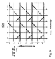
- Figs. 9 and 10 respectively show multi-channel touch panels 900 and 1000 according to two embodiments of the present invention.
- the RC loading of both the driving electrodes and the sensing electrodes can be reduced to one-third.
Landscapes
- Engineering & Computer Science (AREA)
- General Engineering & Computer Science (AREA)
- Theoretical Computer Science (AREA)
- Human Computer Interaction (AREA)
- Physics & Mathematics (AREA)
- General Physics & Mathematics (AREA)
- Position Input By Displaying (AREA)
Applications Claiming Priority (1)
| Application Number | Priority Date | Filing Date | Title |
|---|---|---|---|
| US12/619,149 US8194047B2 (en) | 2009-11-16 | 2009-11-16 | Multi-channel touch panel |
Publications (3)
| Publication Number | Publication Date |
|---|---|
| EP2323024A2 true EP2323024A2 (de) | 2011-05-18 |
| EP2323024A3 EP2323024A3 (de) | 2011-12-14 |
| EP2323024B1 EP2323024B1 (de) | 2014-09-24 |
Family
ID=41800438
Family Applications (1)
| Application Number | Title | Priority Date | Filing Date |
|---|---|---|---|
| EP10151476.8A Active EP2323024B1 (de) | 2009-11-16 | 2010-01-22 | Mehrkanaliger Berührungsbildschirm |
Country Status (4)
| Country | Link |
|---|---|
| US (1) | US8194047B2 (de) |
| EP (1) | EP2323024B1 (de) |
| CN (1) | CN101819483B (de) |
| TW (1) | TWI396120B (de) |
Families Citing this family (36)
| Publication number | Priority date | Publication date | Assignee | Title |
|---|---|---|---|---|
| US8497786B2 (en) * | 2009-03-26 | 2013-07-30 | Freescale Semiconductor, Inc. | Capacitive keyboard with enhanced electrode areas |
| TWI420362B (zh) * | 2010-04-19 | 2013-12-21 | Au Optronics Corp | 觸控面板 |
| US8451250B2 (en) * | 2010-07-22 | 2013-05-28 | Au Optronics Corporation | Capacitive touch device and method of driving same |
| US8730200B2 (en) * | 2010-09-03 | 2014-05-20 | Qualcomm Incorporated | Touch-screen panel comprising cells that have holed or dummied interior portions |
| JP2012063843A (ja) * | 2010-09-14 | 2012-03-29 | On Semiconductor Trading Ltd | タッチセンサ |
| CN102122224B (zh) * | 2011-02-24 | 2013-02-06 | 苏州瀚瑞微电子有限公司 | 一种触控检测的电路模块及方法 |
| US20130342801A1 (en) * | 2011-03-03 | 2013-12-26 | Sharp Kabushiki Kaisha | Liquid crystal display device |
| TWI530849B (zh) * | 2011-04-18 | 2016-04-21 | 聯詠科技股份有限公司 | 電容式觸碰面板的佈局結構 |
| US20120299868A1 (en) * | 2011-05-25 | 2012-11-29 | Broadcom Corporation | High Noise Immunity and High Spatial Resolution Mutual Capacitive Touch Panel |
| CN106648214B (zh) * | 2011-08-26 | 2019-10-11 | 群康科技(深圳)有限公司 | 图像显示系统 |
| US20130100041A1 (en) * | 2011-10-21 | 2013-04-25 | Touch Turns Llc | System for a single-layer sensor having reduced number of interconnect pads for the interconnect periphery of the sensor panel |
| CN103092387B (zh) | 2011-10-27 | 2016-08-03 | 宸鸿科技(厦门)有限公司 | 触控面板 |
| TWI451307B (zh) * | 2011-12-05 | 2014-09-01 | Innolux Corp | 影像顯示系統 |
| KR20130074489A (ko) * | 2011-12-26 | 2013-07-04 | 삼성전기주식회사 | 터치패널의 센싱 전극패턴 |
| US20130176262A1 (en) * | 2012-01-05 | 2013-07-11 | Silicon Integrated Systems Corp. | Projected capacitive touch panel |
| US9081442B2 (en) | 2012-02-27 | 2015-07-14 | Apple Inc. | Split sense lines for negative pixel compensation |
| US8895882B2 (en) * | 2012-03-14 | 2014-11-25 | Htc Corporation | Touch panel |
| CN102622154B (zh) * | 2012-04-27 | 2015-08-05 | 福州华映视讯有限公司 | 电容式触控面板 |
| CN103513818B (zh) * | 2012-06-15 | 2016-08-10 | 宸鸿科技(厦门)有限公司 | 触控装置及其静电屏蔽方法 |
| CN103513830B (zh) * | 2012-06-19 | 2016-08-10 | 上海思立微电子科技有限公司 | 电容式触摸屏及单层电极阵列 |
| KR101966861B1 (ko) | 2012-07-23 | 2019-04-09 | 삼성디스플레이 주식회사 | 터치스크린 패널, 이를 갖는 터치 센싱 장치 및 이의 구동 방법 |
| US10078404B2 (en) * | 2012-07-23 | 2018-09-18 | Samsung Display Co., Ltd. | Touch screen panel and touch sensing apparatus having the same |
| CN103576950B (zh) * | 2012-07-24 | 2016-08-24 | 宸鸿科技(厦门)有限公司 | 触控面板及其制作方法 |
| TWI483165B (zh) | 2012-09-21 | 2015-05-01 | Au Optronics Corp | 電容式觸控感測結構及其應用 |
| US20140104221A1 (en) * | 2012-10-11 | 2014-04-17 | Maxim Integrated Products, Inc. | Capacitive touch panel sensor for mitigating effects of a floating condition |
| CN103793089B (zh) * | 2012-10-30 | 2017-05-17 | 宸鸿科技(厦门)有限公司 | 触控面板 |
| KR101533971B1 (ko) * | 2012-12-13 | 2015-07-06 | 주식회사 지니틱스 | 터치전극패턴, 터치패널, 및 이를 포함하는 터치입력장치 |
| TWI507956B (zh) * | 2013-07-17 | 2015-11-11 | Pixart Imaging Inc | 單層電容式觸控感測器 |
| CN104346004B (zh) * | 2013-07-29 | 2017-08-29 | 原相科技股份有限公司 | 单层电容式触控传感器 |
| TWI510914B (zh) * | 2013-11-19 | 2015-12-01 | Henghao Technology Co Ltd | 觸控面板及其測試裝置 |
| CN104391604B (zh) * | 2014-12-09 | 2018-03-27 | 上海天马微电子有限公司 | 触控电极层及触控装置 |
| CN104777940B (zh) * | 2015-04-30 | 2017-11-14 | 京东方科技集团股份有限公司 | 一种触控电极层以及触摸屏 |
| CN105159485B (zh) * | 2015-06-18 | 2018-06-05 | 京东方科技集团股份有限公司 | 触控面板及其制备方法、显示装置 |
| TWI601048B (zh) * | 2016-12-20 | 2017-10-01 | 友達光電股份有限公司 | 整合觸控之顯示面板 |
| CN107301003B (zh) | 2017-08-08 | 2021-03-23 | 京东方科技集团股份有限公司 | 一种触控面板、其制作方法、触摸屏及显示装置 |
| JP7438854B2 (ja) * | 2020-06-05 | 2024-02-27 | シャープ株式会社 | タッチパネル入力装置 |
Family Cites Families (11)
| Publication number | Priority date | Publication date | Assignee | Title |
|---|---|---|---|---|
| JP4102672B2 (ja) * | 2001-05-22 | 2008-06-18 | アトルア テクノロジーズ インコーポレイテッド | 埋込式刺激電極を用いる表面静電容量センサシステム |
| JP4196924B2 (ja) * | 2004-10-07 | 2008-12-17 | セイコーエプソン株式会社 | 電気光学装置、その駆動方法および電子機器 |
| GB2428306B (en) * | 2005-07-08 | 2007-09-26 | Harald Philipp | Two-dimensional capacitive position sensor |
| US20070063876A1 (en) * | 2005-08-24 | 2007-03-22 | Wong Alex K | Multiple sensing element touch sensor |
| US8072429B2 (en) * | 2006-12-22 | 2011-12-06 | Cypress Semiconductor Corporation | Multi-axial touch-sensor device with multi-touch resolution |
| US20080218487A1 (en) * | 2007-03-07 | 2008-09-11 | Chun-Chung Huang | Capacitive-type touch pad having special arrangement of capacitance sensor |
| US7834862B2 (en) * | 2007-09-28 | 2010-11-16 | Au Optronics Corporation | Touch sensor layout design |
| TWI343017B (en) * | 2007-09-28 | 2011-06-01 | Au Optronics Corp | Capacitive touch panel with low coupling capacitance and display device using the same |
| TWI350474B (en) * | 2007-09-29 | 2011-10-11 | Au Optronics Corp | Capacitive touch panel with low impedance and method of manufacturing capacitive touch panels with low impedance |
| US20090194344A1 (en) * | 2008-01-31 | 2009-08-06 | Avago Technologies Ecbu Ip (Singapore) Pte. Ltd. | Single Layer Mutual Capacitance Sensing Systems, Device, Components and Methods |
| TWI436256B (zh) * | 2008-11-07 | 2014-05-01 | Focaltech Systems Ltd | Mutual capacitive touchpad and modular mutual capacitive touchpad |
-
2009
- 2009-11-16 US US12/619,149 patent/US8194047B2/en active Active
- 2009-12-31 TW TW098146494A patent/TWI396120B/zh active
-
2010
- 2010-01-22 EP EP10151476.8A patent/EP2323024B1/de active Active
- 2010-01-22 CN CN2010101051981A patent/CN101819483B/zh active Active
Non-Patent Citations (1)
| Title |
|---|
| None |
Also Published As
| Publication number | Publication date |
|---|---|
| CN101819483A (zh) | 2010-09-01 |
| TW201118680A (en) | 2011-06-01 |
| US8194047B2 (en) | 2012-06-05 |
| TWI396120B (zh) | 2013-05-11 |
| CN101819483B (zh) | 2011-10-05 |
| EP2323024B1 (de) | 2014-09-24 |
| EP2323024A3 (de) | 2011-12-14 |
| US20110115718A1 (en) | 2011-05-19 |
Similar Documents
| Publication | Publication Date | Title |
|---|---|---|
| EP2323024B1 (de) | Mehrkanaliger Berührungsbildschirm | |
| US8451250B2 (en) | Capacitive touch device and method of driving same | |
| US7834862B2 (en) | Touch sensor layout design | |
| US9684400B2 (en) | Capacitive sensing detection method for an active pixel matrix | |
| US8717312B2 (en) | Touch sensing device | |
| US7924350B2 (en) | Capacitance type touch panel | |
| US8487198B2 (en) | Capacitive touch control device and method thereof | |
| US10488978B2 (en) | Driving chip, circuit film, chip-on-film type driving circuit, and display device having built-in touchscreen | |
| US8922501B2 (en) | Capacitive sensing device comprising cross-shaped sensing elements | |
| EP2762955A1 (de) | Berührungsempfindliche flüssigkristallanzeigevorrichtung | |
| US10521056B2 (en) | Touch screen panel and display device | |
| CN104793819B (zh) | 自电容式触摸屏结构、内嵌式触摸屏以及液晶显示器 | |
| TW201203327A (en) | A panel for position sensors | |
| US20150009421A1 (en) | Capacitive type touch sensing device | |
| KR102107576B1 (ko) | 터치패널 및 이를 이용한 표시장치 | |
| KR20040043903A (ko) | 디지털 저항막 방식의 터치 패널 | |
| US9612692B2 (en) | Position measuring apparatus and driving method thereof | |
| JP2014157611A (ja) | 静電容量式タッチパネルの導電模様構造 | |
| WO2015160516A1 (en) | Capacitive touch sensor with z-shaped electrode pattern | |
| WO2012144765A2 (en) | Touch screen device | |
| EP3180681A1 (de) | Kapazitiver berührungssensor | |
| KR101380817B1 (ko) | 자기정전용량 방식의 정전 터치 패널 장치 및 터치 위치 인식 방법 | |
| CN104965624A (zh) | 触控面板及触控显示装置 |
Legal Events
| Date | Code | Title | Description |
|---|---|---|---|
| PUAI | Public reference made under article 153(3) epc to a published international application that has entered the european phase |
Free format text: ORIGINAL CODE: 0009012 |
|
| 17P | Request for examination filed |
Effective date: 20100222 |
|
| AK | Designated contracting states |
Kind code of ref document: A2 Designated state(s): AT BE BG CH CY CZ DE DK EE ES FI FR GB GR HR HU IE IS IT LI LT LU LV MC MK MT NL NO PL PT RO SE SI SK SM TR |
|
| AX | Request for extension of the european patent |
Extension state: AL BA RS |
|
| PUAL | Search report despatched |
Free format text: ORIGINAL CODE: 0009013 |
|
| AK | Designated contracting states |
Kind code of ref document: A3 Designated state(s): AT BE BG CH CY CZ DE DK EE ES FI FR GB GR HR HU IE IS IT LI LT LU LV MC MK MT NL NO PL PT RO SE SI SK SM TR |
|
| AX | Request for extension of the european patent |
Extension state: AL BA RS |
|
| RIC1 | Information provided on ipc code assigned before grant |
Ipc: G06F 3/044 20060101AFI20111109BHEP |
|
| 17Q | First examination report despatched |
Effective date: 20131119 |
|
| GRAJ | Information related to disapproval of communication of intention to grant by the applicant or resumption of examination proceedings by the epo deleted |
Free format text: ORIGINAL CODE: EPIDOSDIGR1 |
|
| GRAP | Despatch of communication of intention to grant a patent |
Free format text: ORIGINAL CODE: EPIDOSNIGR1 |
|
| GRAP | Despatch of communication of intention to grant a patent |
Free format text: ORIGINAL CODE: EPIDOSNIGR1 |
|
| INTG | Intention to grant announced |
Effective date: 20140604 |
|
| RIN1 | Information on inventor provided before grant (corrected) |
Inventor name: YU, JIAN-SHEN Inventor name: HSIEH, MING-LUN Inventor name: LIU, PO-YUAN Inventor name: KUO, CHUN-KU |
|
| GRAS | Grant fee paid |
Free format text: ORIGINAL CODE: EPIDOSNIGR3 |
|
| GRAA | (expected) grant |
Free format text: ORIGINAL CODE: 0009210 |
|
| AK | Designated contracting states |
Kind code of ref document: B1 Designated state(s): AT BE BG CH CY CZ DE DK EE ES FI FR GB GR HR HU IE IS IT LI LT LU LV MC MK MT NL NO PL PT RO SE SI SK SM TR |
|
| REG | Reference to a national code |
Ref country code: GB Ref legal event code: FG4D |
|
| REG | Reference to a national code |
Ref country code: CH Ref legal event code: EP |
|
| REG | Reference to a national code |
Ref country code: AT Ref legal event code: REF Ref document number: 688887 Country of ref document: AT Kind code of ref document: T Effective date: 20141015 |
|
| REG | Reference to a national code |
Ref country code: IE Ref legal event code: FG4D |
|
| REG | Reference to a national code |
Ref country code: DE Ref legal event code: R096 Ref document number: 602010019091 Country of ref document: DE Effective date: 20141106 |
|
| PG25 | Lapsed in a contracting state [announced via postgrant information from national office to epo] |
Ref country code: GR Free format text: LAPSE BECAUSE OF FAILURE TO SUBMIT A TRANSLATION OF THE DESCRIPTION OR TO PAY THE FEE WITHIN THE PRESCRIBED TIME-LIMIT Effective date: 20141225 Ref country code: SE Free format text: LAPSE BECAUSE OF FAILURE TO SUBMIT A TRANSLATION OF THE DESCRIPTION OR TO PAY THE FEE WITHIN THE PRESCRIBED TIME-LIMIT Effective date: 20140924 Ref country code: LT Free format text: LAPSE BECAUSE OF FAILURE TO SUBMIT A TRANSLATION OF THE DESCRIPTION OR TO PAY THE FEE WITHIN THE PRESCRIBED TIME-LIMIT Effective date: 20140924 Ref country code: NO Free format text: LAPSE BECAUSE OF FAILURE TO SUBMIT A TRANSLATION OF THE DESCRIPTION OR TO PAY THE FEE WITHIN THE PRESCRIBED TIME-LIMIT Effective date: 20141224 Ref country code: FI Free format text: LAPSE BECAUSE OF FAILURE TO SUBMIT A TRANSLATION OF THE DESCRIPTION OR TO PAY THE FEE WITHIN THE PRESCRIBED TIME-LIMIT Effective date: 20140924 |
|
| REG | Reference to a national code |
Ref country code: LT Ref legal event code: MG4D Ref country code: NL Ref legal event code: VDEP Effective date: 20140924 |
|
| PG25 | Lapsed in a contracting state [announced via postgrant information from national office to epo] |
Ref country code: LV Free format text: LAPSE BECAUSE OF FAILURE TO SUBMIT A TRANSLATION OF THE DESCRIPTION OR TO PAY THE FEE WITHIN THE PRESCRIBED TIME-LIMIT Effective date: 20140924 Ref country code: CY Free format text: LAPSE BECAUSE OF FAILURE TO SUBMIT A TRANSLATION OF THE DESCRIPTION OR TO PAY THE FEE WITHIN THE PRESCRIBED TIME-LIMIT Effective date: 20140924 Ref country code: HR Free format text: LAPSE BECAUSE OF FAILURE TO SUBMIT A TRANSLATION OF THE DESCRIPTION OR TO PAY THE FEE WITHIN THE PRESCRIBED TIME-LIMIT Effective date: 20140924 |
|
| REG | Reference to a national code |
Ref country code: AT Ref legal event code: MK05 Ref document number: 688887 Country of ref document: AT Kind code of ref document: T Effective date: 20140924 |
|
| PG25 | Lapsed in a contracting state [announced via postgrant information from national office to epo] |
Ref country code: NL Free format text: LAPSE BECAUSE OF FAILURE TO SUBMIT A TRANSLATION OF THE DESCRIPTION OR TO PAY THE FEE WITHIN THE PRESCRIBED TIME-LIMIT Effective date: 20140924 |
|
| PG25 | Lapsed in a contracting state [announced via postgrant information from national office to epo] |
Ref country code: PT Free format text: LAPSE BECAUSE OF FAILURE TO SUBMIT A TRANSLATION OF THE DESCRIPTION OR TO PAY THE FEE WITHIN THE PRESCRIBED TIME-LIMIT Effective date: 20150126 Ref country code: CZ Free format text: LAPSE BECAUSE OF FAILURE TO SUBMIT A TRANSLATION OF THE DESCRIPTION OR TO PAY THE FEE WITHIN THE PRESCRIBED TIME-LIMIT Effective date: 20140924 Ref country code: RO Free format text: LAPSE BECAUSE OF FAILURE TO SUBMIT A TRANSLATION OF THE DESCRIPTION OR TO PAY THE FEE WITHIN THE PRESCRIBED TIME-LIMIT Effective date: 20140924 Ref country code: EE Free format text: LAPSE BECAUSE OF FAILURE TO SUBMIT A TRANSLATION OF THE DESCRIPTION OR TO PAY THE FEE WITHIN THE PRESCRIBED TIME-LIMIT Effective date: 20140924 Ref country code: SK Free format text: LAPSE BECAUSE OF FAILURE TO SUBMIT A TRANSLATION OF THE DESCRIPTION OR TO PAY THE FEE WITHIN THE PRESCRIBED TIME-LIMIT Effective date: 20140924 Ref country code: ES Free format text: LAPSE BECAUSE OF FAILURE TO SUBMIT A TRANSLATION OF THE DESCRIPTION OR TO PAY THE FEE WITHIN THE PRESCRIBED TIME-LIMIT Effective date: 20140924 Ref country code: IS Free format text: LAPSE BECAUSE OF FAILURE TO SUBMIT A TRANSLATION OF THE DESCRIPTION OR TO PAY THE FEE WITHIN THE PRESCRIBED TIME-LIMIT Effective date: 20150124 |
|
| PG25 | Lapsed in a contracting state [announced via postgrant information from national office to epo] |
Ref country code: AT Free format text: LAPSE BECAUSE OF FAILURE TO SUBMIT A TRANSLATION OF THE DESCRIPTION OR TO PAY THE FEE WITHIN THE PRESCRIBED TIME-LIMIT Effective date: 20140924 Ref country code: PL Free format text: LAPSE BECAUSE OF FAILURE TO SUBMIT A TRANSLATION OF THE DESCRIPTION OR TO PAY THE FEE WITHIN THE PRESCRIBED TIME-LIMIT Effective date: 20140924 |
|
| REG | Reference to a national code |
Ref country code: DE Ref legal event code: R097 Ref document number: 602010019091 Country of ref document: DE |
|
| PG25 | Lapsed in a contracting state [announced via postgrant information from national office to epo] |
Ref country code: BE Free format text: LAPSE BECAUSE OF NON-PAYMENT OF DUE FEES Effective date: 20150131 |
|
| PG25 | Lapsed in a contracting state [announced via postgrant information from national office to epo] |
Ref country code: DK Free format text: LAPSE BECAUSE OF FAILURE TO SUBMIT A TRANSLATION OF THE DESCRIPTION OR TO PAY THE FEE WITHIN THE PRESCRIBED TIME-LIMIT Effective date: 20140924 |
|
| PLBE | No opposition filed within time limit |
Free format text: ORIGINAL CODE: 0009261 |
|
| STAA | Information on the status of an ep patent application or granted ep patent |
Free format text: STATUS: NO OPPOSITION FILED WITHIN TIME LIMIT |
|
| REG | Reference to a national code |
Ref country code: CH Ref legal event code: PL |
|
| PG25 | Lapsed in a contracting state [announced via postgrant information from national office to epo] |
Ref country code: LU Free format text: LAPSE BECAUSE OF FAILURE TO SUBMIT A TRANSLATION OF THE DESCRIPTION OR TO PAY THE FEE WITHIN THE PRESCRIBED TIME-LIMIT Effective date: 20150122 Ref country code: IT Free format text: LAPSE BECAUSE OF FAILURE TO SUBMIT A TRANSLATION OF THE DESCRIPTION OR TO PAY THE FEE WITHIN THE PRESCRIBED TIME-LIMIT Effective date: 20140924 |
|
| 26N | No opposition filed |
Effective date: 20150625 |
|
| PG25 | Lapsed in a contracting state [announced via postgrant information from national office to epo] |
Ref country code: MC Free format text: LAPSE BECAUSE OF FAILURE TO SUBMIT A TRANSLATION OF THE DESCRIPTION OR TO PAY THE FEE WITHIN THE PRESCRIBED TIME-LIMIT Effective date: 20140924 |
|
| PG25 | Lapsed in a contracting state [announced via postgrant information from national office to epo] |
Ref country code: CH Free format text: LAPSE BECAUSE OF NON-PAYMENT OF DUE FEES Effective date: 20150131 Ref country code: LI Free format text: LAPSE BECAUSE OF NON-PAYMENT OF DUE FEES Effective date: 20150131 |
|
| REG | Reference to a national code |
Ref country code: IE Ref legal event code: MM4A |
|
| REG | Reference to a national code |
Ref country code: FR Ref legal event code: PLFP Year of fee payment: 7 |
|
| PG25 | Lapsed in a contracting state [announced via postgrant information from national office to epo] |
Ref country code: IE Free format text: LAPSE BECAUSE OF NON-PAYMENT OF DUE FEES Effective date: 20150122 |
|
| PG25 | Lapsed in a contracting state [announced via postgrant information from national office to epo] |
Ref country code: SI Free format text: LAPSE BECAUSE OF FAILURE TO SUBMIT A TRANSLATION OF THE DESCRIPTION OR TO PAY THE FEE WITHIN THE PRESCRIBED TIME-LIMIT Effective date: 20140924 |
|
| REG | Reference to a national code |
Ref country code: FR Ref legal event code: PLFP Year of fee payment: 8 |
|
| PG25 | Lapsed in a contracting state [announced via postgrant information from national office to epo] |
Ref country code: MT Free format text: LAPSE BECAUSE OF FAILURE TO SUBMIT A TRANSLATION OF THE DESCRIPTION OR TO PAY THE FEE WITHIN THE PRESCRIBED TIME-LIMIT Effective date: 20140924 |
|
| PG25 | Lapsed in a contracting state [announced via postgrant information from national office to epo] |
Ref country code: HU Free format text: LAPSE BECAUSE OF FAILURE TO SUBMIT A TRANSLATION OF THE DESCRIPTION OR TO PAY THE FEE WITHIN THE PRESCRIBED TIME-LIMIT; INVALID AB INITIO Effective date: 20100122 Ref country code: SM Free format text: LAPSE BECAUSE OF FAILURE TO SUBMIT A TRANSLATION OF THE DESCRIPTION OR TO PAY THE FEE WITHIN THE PRESCRIBED TIME-LIMIT Effective date: 20140924 Ref country code: BG Free format text: LAPSE BECAUSE OF FAILURE TO SUBMIT A TRANSLATION OF THE DESCRIPTION OR TO PAY THE FEE WITHIN THE PRESCRIBED TIME-LIMIT Effective date: 20140924 |
|
| PG25 | Lapsed in a contracting state [announced via postgrant information from national office to epo] |
Ref country code: TR Free format text: LAPSE BECAUSE OF FAILURE TO SUBMIT A TRANSLATION OF THE DESCRIPTION OR TO PAY THE FEE WITHIN THE PRESCRIBED TIME-LIMIT Effective date: 20140924 |
|
| REG | Reference to a national code |
Ref country code: FR Ref legal event code: PLFP Year of fee payment: 9 |
|
| PG25 | Lapsed in a contracting state [announced via postgrant information from national office to epo] |
Ref country code: MK Free format text: LAPSE BECAUSE OF FAILURE TO SUBMIT A TRANSLATION OF THE DESCRIPTION OR TO PAY THE FEE WITHIN THE PRESCRIBED TIME-LIMIT Effective date: 20140924 |
|
| PGFP | Annual fee paid to national office [announced via postgrant information from national office to epo] |
Ref country code: GB Payment date: 20231130 Year of fee payment: 15 |
|
| PGFP | Annual fee paid to national office [announced via postgrant information from national office to epo] |
Ref country code: FR Payment date: 20231212 Year of fee payment: 15 |
|
| PGFP | Annual fee paid to national office [announced via postgrant information from national office to epo] |
Ref country code: DE Payment date: 20231205 Year of fee payment: 15 |