EP2322747A2 - Sliding door assembly - Google Patents
Sliding door assembly Download PDFInfo
- Publication number
- EP2322747A2 EP2322747A2 EP10190673A EP10190673A EP2322747A2 EP 2322747 A2 EP2322747 A2 EP 2322747A2 EP 10190673 A EP10190673 A EP 10190673A EP 10190673 A EP10190673 A EP 10190673A EP 2322747 A2 EP2322747 A2 EP 2322747A2
- Authority
- EP
- European Patent Office
- Prior art keywords
- sliding
- passage
- door system
- sliding door
- bottom profile
- Prior art date
- Legal status (The legal status is an assumption and is not a legal conclusion. Google has not performed a legal analysis and makes no representation as to the accuracy of the status listed.)
- Granted
Links
- 230000007704 transition Effects 0.000 claims description 5
- 239000011521 glass Substances 0.000 abstract description 2
- 239000002689 soil Substances 0.000 description 7
- 230000008878 coupling Effects 0.000 description 4
- 238000010168 coupling process Methods 0.000 description 4
- 238000005859 coupling reaction Methods 0.000 description 4
- 229910000831 Steel Inorganic materials 0.000 description 1
- XAGFODPZIPBFFR-UHFFFAOYSA-N aluminium Chemical compound [Al] XAGFODPZIPBFFR-UHFFFAOYSA-N 0.000 description 1
- 229910052782 aluminium Inorganic materials 0.000 description 1
- 238000009434 installation Methods 0.000 description 1
- 239000000463 material Substances 0.000 description 1
- 238000005192 partition Methods 0.000 description 1
- 239000004033 plastic Substances 0.000 description 1
- 230000001681 protective effect Effects 0.000 description 1
- 239000007787 solid Substances 0.000 description 1
- 239000010959 steel Substances 0.000 description 1
- 230000037072 sun protection Effects 0.000 description 1
- 239000002023 wood Substances 0.000 description 1
Images


Classifications
-
- E—FIXED CONSTRUCTIONS
- E05—LOCKS; KEYS; WINDOW OR DOOR FITTINGS; SAFES
- E05D—HINGES OR SUSPENSION DEVICES FOR DOORS, WINDOWS OR WINGS
- E05D11/00—Additional features or accessories of hinges
- E05D11/08—Friction devices between relatively-movable hinge parts
-
- E—FIXED CONSTRUCTIONS
- E05—LOCKS; KEYS; WINDOW OR DOOR FITTINGS; SAFES
- E05D—HINGES OR SUSPENSION DEVICES FOR DOORS, WINDOWS OR WINGS
- E05D15/00—Suspension arrangements for wings
- E05D15/06—Suspension arrangements for wings for wings sliding horizontally more or less in their own plane
- E05D15/0621—Details, e.g. suspension or supporting guides
- E05D15/0626—Details, e.g. suspension or supporting guides for wings suspended at the top
- E05D15/0652—Tracks
-
- E—FIXED CONSTRUCTIONS
- E06—DOORS, WINDOWS, SHUTTERS, OR ROLLER BLINDS IN GENERAL; LADDERS
- E06B—FIXED OR MOVABLE CLOSURES FOR OPENINGS IN BUILDINGS, VEHICLES, FENCES OR LIKE ENCLOSURES IN GENERAL, e.g. DOORS, WINDOWS, BLINDS, GATES
- E06B1/00—Border constructions of openings in walls, floors, or ceilings; Frames to be rigidly mounted in such openings
- E06B1/70—Sills; Thresholds
-
- E—FIXED CONSTRUCTIONS
- E06—DOORS, WINDOWS, SHUTTERS, OR ROLLER BLINDS IN GENERAL; LADDERS
- E06B—FIXED OR MOVABLE CLOSURES FOR OPENINGS IN BUILDINGS, VEHICLES, FENCES OR LIKE ENCLOSURES IN GENERAL, e.g. DOORS, WINDOWS, BLINDS, GATES
- E06B3/00—Window sashes, door leaves, or like elements for closing wall or like openings; Layout of fixed or moving closures, e.g. windows in wall or like openings; Features of rigidly-mounted outer frames relating to the mounting of wing frames
- E06B3/32—Arrangements of wings characterised by the manner of movement; Arrangements of movable wings in openings; Features of wings or frames relating solely to the manner of movement of the wing
- E06B3/34—Arrangements of wings characterised by the manner of movement; Arrangements of movable wings in openings; Features of wings or frames relating solely to the manner of movement of the wing with only one kind of movement
- E06B3/42—Sliding wings; Details of frames with respect to guiding
- E06B3/46—Horizontally-sliding wings
-
- E—FIXED CONSTRUCTIONS
- E05—LOCKS; KEYS; WINDOW OR DOOR FITTINGS; SAFES
- E05Y—INDEXING SCHEME RELATING TO HINGES OR OTHER SUSPENSION DEVICES FOR DOORS, WINDOWS OR WINGS AND DEVICES FOR MOVING WINGS INTO OPEN OR CLOSED POSITION, CHECKS FOR WINGS AND WING FITTINGS NOT OTHERWISE PROVIDED FOR, CONCERNED WITH THE FUNCTIONING OF THE WING
- E05Y2900/00—Application of doors, windows, wings or fittings thereof
- E05Y2900/10—Application of doors, windows, wings or fittings thereof for buildings or parts thereof
- E05Y2900/13—Application of doors, windows, wings or fittings thereof for buildings or parts thereof characterised by the type of wing
- E05Y2900/132—Doors
Definitions
- the present invention relates to a sliding door system with at least one sliding element, which is guided on the bottom side slidably on a rail and is movable from a closing position covering a passage in an open position.
- the rails have a strip-shaped contour that protrudes upwards in the opening position when the sliding leaf is arranged and forms a tripping edge.
- Especially people with walking problems can stumble or wheeled objects, such as wheelchairs, mobile furniture or scooters, can run over bumps only bad.
- a bottom profile is provided, which is guided along a rail and, when the at least one sliding element is arranged in the opening position, is positioned on the passage such that a substantially planar transition is formed on the passage.
- the rail for guiding the one sliding element or the rails for guiding the forms Sliding elements no longer the walk-out surface, but in the region of the one or more rails, the surface is formed in the region of the passage through the bottom profile, which is arranged in the opening position at the passage in the arrangement of the sliding elements or.
- the bottom side rail is arranged below a ground plane and the top of the bottom profile is aligned with a ground plane.
- the ground plane is formed by a flat surface formed by the top of the soil profile and the surrounding adjacent bottom surface.
- the at least one sliding element is movably mounted on a window frame.
- the window frame can be adapted to predetermined sizes of building openings. It is also possible to provide only one or more rails on the bottom side instead of a circumferential frame.
- the bottom profile is coupled to at least one sliding element.
- a plurality of successively arranged sliding elements can be provided, which are each mounted individually moveable along a rail, so that in the provision of two sliding elements two rails and three sliding elements three rails are provided.
- the bottom profile then covers all the rails for guiding the sliding elements, whereby it is of course also possible to provide a bottom profile for each sliding element, so that a bottom profile covers one rail each.
- each sliding element is releasably coupled to the bottom profile, wherein the bottom profile is then pulled into the passage when the last sliding element is moved to an open position, because only when all the sliding elements are arranged in the open position is the passage allowed to pass and then become the soil profile needed.
- the soil profile can mechanically, for example by snap-in connections, electrically, pneumatically, hydraulically or magnetically coupled to the sliding elements be.
- the sliding elements are individually movable, with a sliding element remains connected to the soil profile.
- the sliding door system comprises a window frame with three panels, in which the passage is arranged in the middle panel.
- a pocket for receiving at least one sliding element may be formed, wherein the pocket may optionally be formed in the frame or even in a building opening or otherwise designed receptacle.
- the planar bottom profile for providing a planar transition may optionally comprise above another element, for example a solid element for reducing the width of the passage or a wing element which can be pivoted like a door or window. This extends the functionality of the sliding door system.
- the further element may be firmly connected to the soil profile or be movable independently of the soil profile.
- a sliding door system 1 comprises a frame 2, in which three fields 3, 4 and 5 are arranged.
- a middle panel 3 forms a passage which is separated from the lateral panels 4 and 5 by vertical posts 18.
- the fields 4 and 5 can be used as fixed elements with insulating glass panes, filling plates, a Masonry or a pocket for receiving sliding elements 10, 11 and 12 may be formed.
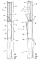
- FIG. 1 In the area of the passage 3 are in FIG. 1 three sliding elements 10, 11 and 12 arranged one behind the other, the bottom side are each supported on a rail 7, 8 and 9.
- a sliding element 10 can be moved as a movable lsolierglasemia on the rail 9
- a middle sliding element 11 may be formed as a fly screen and is movable on the rail 8, while the sliding element 12 is movable as sun protection on the rail 7.
- the sliding elements 10, 11 and 12 may also comprise other elements, in particular photovoltaic elements, insulating elements or protective elements.
- the outermost sliding element 12 (sunshade) has moved into an opening position and is therefore located in the lateral field 5 FIG. 3
- the middle sliding element is moved to the open position, where it accordingly FIG. 4
- FIG. 6 a position is shown in which all the sliding elements 10, 11 and 12 are moved into an opening position, so that the central panel 3 is open with the passage.
- a bottom profile 13 is now arranged on the bottom side, which forms a flat passage.
- the soil profile on a substantially flat surface which is optionally profiled for slip resistance by a few millimeters, but otherwise lies with the adjacent ground plane 17 on a plane.
- the bottom profile 13 is frontally provided with a holder 14 which has three projections 15. Each projection 15 is connected to a coupling portion 16 on one of the sliding elements 10, 11 and 12.
- At least one of the sliding elements 10, 11 or 12 is decoupled from the bottom profile 13 and the bottom profile 13 is arranged in the lateral field 4. Only when all the sliding elements 10, 11 and 12 are moved to an open position, the bottom profile 13 is pulled into the middle panel 3, each the sliding elements 10, 11 or 12 can pull the bottom profile 13 into the passage 3, depending on which coupling element 16 is in engagement with the projection 15 on the strip 14.
- the coupling can be done mechanically via locking elements, but also hydraulically, electrically or magnetically. If one of the sliding elements 10, 11 or 12 is moved into a closed position, the bottom profile 13 moves back into the field 4 at the same time.
- FIG. 7A Fig. 3 is a sectional view through the passage 3 when all the slide members 10, 11 and 12 are arranged in a closed position.
- the sliding elements 10,11 and 12 are each supported by one or more rollers 20, which roll on a running surface on the rails 7, 8 or 9.
- the rails 7, 8 and 9 are arranged below a ground plane, which is formed by the surface of the adjacent floor panels 17 and 19.
- FIG. 7B is a sectional view through the sliding door system 1 shown, when all the sliding elements 10, 11 and 12 are arranged in an open position, so that the bottom profile 13 is arranged on the passage 3 ( FIG. 6 ).
- the bottom profile 13 is also supported by rollers 20 on the rails 7 and 9, wherein the middle rail 8 can optionally also serve to support the bottom profile 13.
- the bottom profile 13 is formed as a hollow profile, preferably made of aluminum, but may also be made of wood, plastic, steel or other materials. At the top of the bottom profile 13 a slight profiling is incorporated, which forms a slip resistance.
- the top of the bottom profile 13 is at a height with the adjacent floor panels 17 and 19, so that a substantially planar transition between the floor panels 17 and 19 and the bottom profile 13 is formed.
- a further sliding element which may optionally be fixedly connected to the bottom profile 13.
- the sliding element comprises a passage 25 and a fixed element 26, which are spaced apart by a partition wall 27. Thereby, the wide passage of the central panel 3 can be divided, whereby the advantages of the flat floor profile 13 can be further utilized.
- the movement of the sliding elements 10, 11 and 12 and the coupling with the bottom profile 13 is formed as in the previous embodiment.
- FIG. 9 a further alternative of a sliding door system is shown in which above the bottom profile 13, a door member 30 is arranged.
- the door element comprises a pivotable door 31, which is pivotably mounted on a frame profile 32.
- the sliding door system 1 can provide a closable passage 3, at which the advantages of a smooth passage can be used, but also a closure by one or more sliding elements 10, 11 or 12 is possible.
- sliding elements 10, 11 and 12 are shown in each case. It is of course possible to provide even a single sliding element, as guided on a bottom rail. Also, two or more sliding elements may be provided.
Landscapes
- Engineering & Computer Science (AREA)
- Civil Engineering (AREA)
- Structural Engineering (AREA)
- Mechanical Engineering (AREA)
- Wing Frames And Configurations (AREA)
- Support Devices For Sliding Doors (AREA)
Abstract
Description
Die vorliegende Erfindung betrifft eine Schiebetüranlage mit mindestens einem Schiebeelement, das bodenseitig verschiebbar an einer Schiene geführt ist und von einer einen Durchgang überdeckenden Schließposition in eine Öffnungsposition bewegbar ist.The present invention relates to a sliding door system with at least one sliding element, which is guided on the bottom side slidably on a rail and is movable from a closing position covering a passage in an open position.
Es gibt Schiebeflügel, die an einer bodenseitigen Schiene über Laufrollen geführt sind. Die Schienen besitzen dabei eine leistenförmige Kontur, die bei Anordnung des Schiebeflügels in die Öffnungsposition nach oben hervorsteht und eine Stolperkante ausbildet. Gerade Menschen mit Gehproblemen können stolpern oder fahrbare Gegenstände, wie Rollstühle, fahrbare Möbel oder Roller, können Unebenheiten nur schlecht überfahren.There are sliding sashes that are guided on a bottom rail over rollers. The rails have a strip-shaped contour that protrudes upwards in the opening position when the sliding leaf is arranged and forms a tripping edge. Especially people with walking problems can stumble or wheeled objects, such as wheelchairs, mobile furniture or scooters, can run over bumps only bad.
Es ist daher Aufgabe der vorliegenden Erfindung, eine Schiebetüranlage zu schaffen, die einen Durchgang aufweist, der leicht passiert werden kann.It is therefore an object of the present invention to provide a sliding door system having a passage that can be easily passed.
Diese Aufgabe wird mit einer Schiebetüranlage mit den Merkmalen des Anspruches 1 gelöst.This object is achieved with a sliding door system with the features of
Erfindungsgemäß ist ein Bodenprofil vorgesehen, das entlang einer Schiene geführt ist und bei Anordnung des mindestens einen Schiebeelementes in der Öffnungsposition an dem Durchgang so positioniert ist, dass ein im Wesentlichen ebener Übergang an dem Durchgang ausgebildet ist. Dadurch bildet die Schiene zur Führung des einen Schiebeelementes bzw. die Schienen zur Führung der Schiebeelemente nicht mehr die begehbare Oberfläche aus, sondern in dem Bereich der einen oder mehreren Schienen wird die Oberfläche im Bereich des Durchgangs durch das Bodenprofil gebildet, das bei Anordnung des oder der Schiebeelemente in der Öffnungsposition am Durchgang angeordnet ist. Dadurch lässt sich ein im Wesentlichen ebener Übergang bereitstellen, der von Personen leicht begangen werden kann, auch bei Gehproblemen, sowie ein Überfahren mit Fahrzeugen, Möbeln und anderen Gefährten ermöglicht,According to the invention, a bottom profile is provided, which is guided along a rail and, when the at least one sliding element is arranged in the opening position, is positioned on the passage such that a substantially planar transition is formed on the passage. As a result, the rail for guiding the one sliding element or the rails for guiding the forms Sliding elements no longer the walk-out surface, but in the region of the one or more rails, the surface is formed in the region of the passage through the bottom profile, which is arranged in the opening position at the passage in the arrangement of the sliding elements or. This can provide a substantially level transition that can be easily made by people, even with walking problems, and allows driving over vehicles, furniture and other companions,
Vorzugsweise ist die bodenseitig angeordnete Schiene unterhalb einer Bodenebene angeordnet und die Oberseite des Bodenprofils fluchtet mit einer Bodenebene. Die Bodenebene wird durch eine ebene Fläche gebildet, die durch die Oberseite des Bodenprofils sowie die umgebende benachbarte Bodenfläche gebildet ist.Preferably, the bottom side rail is arranged below a ground plane and the top of the bottom profile is aligned with a ground plane. The ground plane is formed by a flat surface formed by the top of the soil profile and the surrounding adjacent bottom surface.
Für eine leichte Montage der Schiebetüranlage ist das mindestens eine Schiebeelement an einem Blendrahmen verfahrbar gelagert. Der Blendrahmen kann an vorbestimmte Größen von Gebäudeöffnungen angepasst sein. Es ist auch möglich, statt eines umlaufenden Blendrahmens nur ein oder mehrere Schienen bodenseitig vorzusehen.For easy installation of the sliding door system, the at least one sliding element is movably mounted on a window frame. The window frame can be adapted to predetermined sizes of building openings. It is also possible to provide only one or more rails on the bottom side instead of a circumferential frame.
Gemäß einer bevorzugten Ausgestaltung ist das Bodenprofil mit mindestens einem Schiebeelement gekoppelt. Dabei können mehrere hintereinander angeordnete Schiebeelemente vorgesehen sein, die jeweils einzeln entlang einer Schiene verfahrbar gelagert sind, so dass bei Vorsehung von zwei Schiebeelementen zwei Schienen und bei drei Schiebeelementen drei Schienen vorgesehen sind. Das Bodenprofil überdeckt dann sämtliche Schienen zur Führung der Schiebeelemente, wobei es natürlich auch möglich ist, für jedes Schiebeelement ein Bodenprofil vorzusehen, so dass ein Bodenprofil jeweils eine Schiene überdeckt.According to a preferred embodiment, the bottom profile is coupled to at least one sliding element. In this case, a plurality of successively arranged sliding elements can be provided, which are each mounted individually moveable along a rail, so that in the provision of two sliding elements two rails and three sliding elements three rails are provided. The bottom profile then covers all the rails for guiding the sliding elements, whereby it is of course also possible to provide a bottom profile for each sliding element, so that a bottom profile covers one rail each.
Vorzugsweise ist jedes Schiebeelement mit dem Bodenprofil lösbar gekoppelt, wobei das Bodenprofil dann in den Durchgang gezogen wird, wenn das letzte Schiebeelement in eine Öffnungsposition bewegt wird, denn nur wenn alle Schiebeelemente in der Öffnungsposition angeordnet sind, wird ein Übertreten des Durchganges ermöglicht und dann wird das Bodenprofil benötigt. Das Bodenprofil kann dabei mechanisch, beispielsweise durch Rastverbindungen, elektrisch, pneumatisch, hydraulisch oder magnetisch mit den Schiebeelementen gekoppelt sein. Die Schiebeelemente sind dabei einzeln bewegbar, wobei ein Schiebeelement jeweils mit dem Bodenprofil verbunden bleibt.Preferably, each sliding element is releasably coupled to the bottom profile, wherein the bottom profile is then pulled into the passage when the last sliding element is moved to an open position, because only when all the sliding elements are arranged in the open position is the passage allowed to pass and then become the soil profile needed. The soil profile can mechanically, for example by snap-in connections, electrically, pneumatically, hydraulically or magnetically coupled to the sliding elements be. The sliding elements are individually movable, with a sliding element remains connected to the soil profile.
In einer weiteren Ausgestaltung umfasst die Schiebetüranlage einen Blendrahmen mit drei Feldern, bei dem in dem mittleren Feld der Durchgang angeordnet ist. In einem seitlichen Feld neben dem Durchgang kann eine Tasche zur Aufnahme mindestens eines Schiebeelementes ausgebildet sein, wobei die Tasche wahlweise in dem Blendrahmen oder auch nur in einer Gebäudeöffnung oder anders gestalteten Aufnahme ausgebildet sein kann.In a further embodiment, the sliding door system comprises a window frame with three panels, in which the passage is arranged in the middle panel. In a lateral field next to the passage, a pocket for receiving at least one sliding element may be formed, wherein the pocket may optionally be formed in the frame or even in a building opening or otherwise designed receptacle.
Das ebene Bodenprofil zur Bereitstellung eines ebenen Überganges kann optional oberhalb ein weiteres Element aufweisen, beispielsweise ein Festelement zur Verminderung der Breite des Durchganges oder ein Flügelelement, das wie eine Tür bzw. Fenster verschwenkt werden kann. Dadurch wird die Funktionalität der Schiebetüranlage erweitert. Das weitere Element kann dabei fest mit dem Bodenprofil verbunden sein oder unabhängig von dem Bodenprofil bewegbar sein.The planar bottom profile for providing a planar transition may optionally comprise above another element, for example a solid element for reducing the width of the passage or a wing element which can be pivoted like a door or window. This extends the functionality of the sliding door system. The further element may be firmly connected to the soil profile or be movable independently of the soil profile.
Die Erfindung wird nachfolgend anhand mehrerer Ausführungsbeispiele mit Bezug auf die beigefügten Zeichnungen näher erläutert. Es zeigen:
Figuren 1 bis 6- mehrere Ansichten eines Ausführungsbeispieles einer er- findungsgemäßen Schiebetüranlage in unterschiedlichen Positionen;
- Figuren 7A und 7B
- zwei Schnittansichten der Schiebetüranlage der
Figuren 1 bis 6 Figur 8- eine schematische Draufsicht auf eine Schiebetüranlage gemäß einer weiteren Ausführungsform, und
Figur 9- eine schematische Draufsicht auf eine Schiebetüranlage gemäß einer weiteren Ausführungsform.
- FIGS. 1 to 6
- several views of an embodiment of a sliding door system according to the invention in different positions;
- FIGS. 7A and 7B
- two sectional views of the sliding door of the
FIGS. 1 to 6 ; - FIG. 8
- a schematic plan view of a sliding door system according to another embodiment, and
- FIG. 9
- a schematic plan view of a sliding door system according to another embodiment.
Eine Schiebetüranlage 1 umfasst einen Blendrahmen 2, in dem drei Felder 3, 4 und 5 angeordnet sind. Ein mittleres Feld 3 bildet einen Durchgang aus, der über vertikale Pfosten 18 von den seitlichen Feldern 4 und 5 getrennt ist. Die Felder 4 und 5 können als Festelemente mit Isolierglasscheiben, Füllungsplatten, einem Mauerwerk oder einer Tasche zur Aufnahme von Schiebelementen 10, 11 und 12 ausgebildet sein.A sliding
Im Bereich des Durchganges 3 sind in
In
In
Das Bodenprofil 13 ist stirnseitig mit einer Halterung 14 versehen, die drei Vorsprünge 15 aufweist. Jeder Vorsprung 15 ist mit einem Kopplungsabschnitt 16 an einem der Schiebeelemente 10, 11 und 12 verbunden. In den
In
In
Bei dem in
In
ln den dargestellten Ausführungsbeispielen sind jeweils drei Schiebeelemente 10, 11 und 12 gezeigt. Es ist natürlich möglich, auch nur ein einziges Schiebeelement vorzusehen, da an einer bodenseitigen Schiene geführt ist. Auch zwei oder mehr Schiebeelemente können vorgesehen sein.In the illustrated embodiments, three sliding
Claims (9)
Applications Claiming Priority (1)
| Application Number | Priority Date | Filing Date | Title |
|---|---|---|---|
| DE200920013731 DE202009013731U1 (en) | 2009-11-13 | 2009-11-13 | sliding door system |
Publications (3)
| Publication Number | Publication Date |
|---|---|
| EP2322747A2 true EP2322747A2 (en) | 2011-05-18 |
| EP2322747A3 EP2322747A3 (en) | 2013-05-01 |
| EP2322747B1 EP2322747B1 (en) | 2017-12-27 |
Family
ID=43480931
Family Applications (1)
| Application Number | Title | Priority Date | Filing Date |
|---|---|---|---|
| EP10190673.3A Active EP2322747B1 (en) | 2009-11-13 | 2010-11-10 | Sliding door assembly |
Country Status (3)
| Country | Link |
|---|---|
| EP (1) | EP2322747B1 (en) |
| DE (1) | DE202009013731U1 (en) |
| ES (1) | ES2662045T3 (en) |
Families Citing this family (1)
| Publication number | Priority date | Publication date | Assignee | Title |
|---|---|---|---|---|
| JP6740021B2 (en) * | 2016-06-16 | 2020-08-12 | 阿部興業株式会社 | Double sliding door structure |
Family Cites Families (7)
| Publication number | Priority date | Publication date | Assignee | Title |
|---|---|---|---|---|
| GB191313915A (en) * | 1913-06-16 | 1914-06-16 | Albert Gottschalk | Improvements in or relating to Fluid Pressure Apparatus for Operating and Controlling Doors, Gates or the like. |
| JP4338496B2 (en) * | 2003-10-28 | 2009-10-07 | 不二サッシ株式会社 | Lid structure in the opening of the lower frame of the sliding door structure |
| US7290371B2 (en) * | 2004-05-26 | 2007-11-06 | Jack Zimmerman | Combined security strut apparatus and threshold cover for sliding doors and windows |
| DE102005035220A1 (en) * | 2004-08-10 | 2006-06-01 | Inge Frey | Sliding element e.g. for windows, has lengthwise-running shifting movement with part of wall being able to open or lockable and in closed position gap opening is lockable by sealing element movable by magnetic forces |
| DE102005035222A1 (en) * | 2004-08-10 | 2006-02-23 | Inge Frey | Sliding element e.g. for windows, has lengthwise-running shifting movement with part of wall being able to open or lockable and in closed position gap opening is lockable by sealing element movable by magnetic forces |
| FR2911627A1 (en) * | 2007-01-23 | 2008-07-25 | Bubendorff Sa | Structural-shaped guiding sill for sliding opening of e.g. garage door, has sealing and closing units to close guiding groove, and with covering joint extended above groove such that joint is supported on longitudinal edges of groove |
| SE0700550L (en) * | 2007-03-07 | 2007-11-13 | Nordiska Balco Ab | Window shutter, sliding window device and balcony glazing |
-
2009
- 2009-11-13 DE DE200920013731 patent/DE202009013731U1/en not_active Expired - Lifetime
-
2010
- 2010-11-10 ES ES10190673.3T patent/ES2662045T3/en active Active
- 2010-11-10 EP EP10190673.3A patent/EP2322747B1/en active Active
Non-Patent Citations (1)
| Title |
|---|
| None |
Also Published As
| Publication number | Publication date |
|---|---|
| EP2322747A3 (en) | 2013-05-01 |
| ES2662045T3 (en) | 2018-04-05 |
| DE202009013731U1 (en) | 2011-03-24 |
| EP2322747B1 (en) | 2017-12-27 |
Similar Documents
| Publication | Publication Date | Title |
|---|---|---|
| WO2005068764A1 (en) | Frame for a sliding door or a sliding window | |
| EP3225771A1 (en) | Threshold for a sliding door and sliding door | |
| WO2012156468A1 (en) | Sliding wall with at least one panel | |
| EP0747565A1 (en) | Mounting element for closing an opening in a building | |
| DE102005035220A1 (en) | Sliding element e.g. for windows, has lengthwise-running shifting movement with part of wall being able to open or lockable and in closed position gap opening is lockable by sealing element movable by magnetic forces | |
| EP2322747B1 (en) | Sliding door assembly | |
| EP2157898A2 (en) | Sliding door and shower partition with sliding door | |
| DE102016006706A1 (en) | Gate, in particular sectional door and door drive | |
| DE19829783B4 (en) | Sliding door or partition wall system | |
| AT11536U1 (en) | ROOFING, ESPECIALLY FOR A TERRACE CLOSED TO A BUILDING EXTERIOR WALL | |
| DE102016111410A1 (en) | Central support for a building opening with a large clear width | |
| DE2610398A1 (en) | Sliding openable terrace roof - has telescopically displaceable sections on slide rails in horizontal frame | |
| EP2381056A1 (en) | Floor guide for a side sectional door | |
| DE4325698C2 (en) | Side door | |
| EP2072744B1 (en) | Architrave profile for a lifting sliding door | |
| DE202007019187U1 (en) | sectional | |
| DE19751657C2 (en) | Glass wall for attic rooms under a sloping roof | |
| DE102021115544A1 (en) | sliding door system | |
| DE202009000114U1 (en) | Sliding revolving door for fire protection purposes | |
| DE102009004352A1 (en) | Thermally insulated wall element unit for building facades | |
| DE146723C (en) | ||
| AT503892B1 (en) | SECTIONAL | |
| DE202011000409U1 (en) | Device for roofing terraces and similar open spaces | |
| DE2619737A1 (en) | Garage door with horizontal pivoted slats - has vertical guide rails connected at top to horizontal members | |
| DE3416535A1 (en) | Barrel-vault roofing consisting of acrylic glass |
Legal Events
| Date | Code | Title | Description |
|---|---|---|---|
| PUAI | Public reference made under article 153(3) epc to a published international application that has entered the european phase |
Free format text: ORIGINAL CODE: 0009012 |
|
| AK | Designated contracting states |
Kind code of ref document: A2 Designated state(s): AL AT BE BG CH CY CZ DE DK EE ES FI FR GB GR HR HU IE IS IT LI LT LU LV MC MK MT NL NO PL PT RO RS SE SI SK SM TR |
|
| AX | Request for extension of the european patent |
Extension state: BA ME |
|
| PUAL | Search report despatched |
Free format text: ORIGINAL CODE: 0009013 |
|
| AK | Designated contracting states |
Kind code of ref document: A3 Designated state(s): AL AT BE BG CH CY CZ DE DK EE ES FI FR GB GR HR HU IE IS IT LI LT LU LV MC MK MT NL NO PL PT RO RS SE SI SK SM TR |
|
| AX | Request for extension of the european patent |
Extension state: BA ME |
|
| RIC1 | Information provided on ipc code assigned before grant |
Ipc: E05D 15/06 20060101ALI20130326BHEP Ipc: E05D 11/08 20060101AFI20130326BHEP Ipc: E05D 15/08 20060101ALN20130326BHEP Ipc: E06B 3/46 20060101ALI20130326BHEP |
|
| RBV | Designated contracting states (corrected) |
Designated state(s): AL AT BE BG CH CY CZ DE DK EE ES FI FR GB GR HR HU IE IS IT LI LT LU LV MC MK MT NL NO PL PT RO RS SE SI SK SM TR |
|
| 17P | Request for examination filed |
Effective date: 20130706 |
|
| 17Q | First examination report despatched |
Effective date: 20160304 |
|
| RIC1 | Information provided on ipc code assigned before grant |
Ipc: E05D 15/06 20060101ALI20170316BHEP Ipc: E05D 15/08 20060101ALN20170316BHEP Ipc: E06B 1/70 20060101ALI20170316BHEP Ipc: E05D 11/08 20060101AFI20170316BHEP Ipc: E06B 3/46 20060101ALI20170316BHEP |
|
| GRAP | Despatch of communication of intention to grant a patent |
Free format text: ORIGINAL CODE: EPIDOSNIGR1 |
|
| INTG | Intention to grant announced |
Effective date: 20170602 |
|
| GRAS | Grant fee paid |
Free format text: ORIGINAL CODE: EPIDOSNIGR3 |
|
| GRAA | (expected) grant |
Free format text: ORIGINAL CODE: 0009210 |
|
| AK | Designated contracting states |
Kind code of ref document: B1 Designated state(s): AL AT BE BG CH CY CZ DE DK EE ES FI FR GB GR HR HU IE IS IT LI LT LU LV MC MK MT NL NO PL PT RO RS SE SI SK SM TR |
|
| REG | Reference to a national code |
Ref country code: GB Ref legal event code: FG4D Free format text: NOT ENGLISH |
|
| REG | Reference to a national code |
Ref country code: CH Ref legal event code: EP |
|
| REG | Reference to a national code |
Ref country code: AT Ref legal event code: REF Ref document number: 958450 Country of ref document: AT Kind code of ref document: T Effective date: 20180115 |
|
| REG | Reference to a national code |
Ref country code: IE Ref legal event code: FG4D Free format text: LANGUAGE OF EP DOCUMENT: GERMAN |
|
| REG | Reference to a national code |
Ref country code: CH Ref legal event code: NV Representative=s name: KATZAROV S.A., CH |
|
| REG | Reference to a national code |
Ref country code: DE Ref legal event code: R096 Ref document number: 502010014503 Country of ref document: DE |
|
| REG | Reference to a national code |
Ref country code: CH Ref legal event code: PCAR Free format text: NEW ADDRESS: AVENUE DES MORGINES 12, 1213 PETIT-LANCY (CH) |
|
| REG | Reference to a national code |
Ref country code: ES Ref legal event code: FG2A Ref document number: 2662045 Country of ref document: ES Kind code of ref document: T3 Effective date: 20180405 |
|
| PG25 | Lapsed in a contracting state [announced via postgrant information from national office to epo] |
Ref country code: NO Free format text: LAPSE BECAUSE OF FAILURE TO SUBMIT A TRANSLATION OF THE DESCRIPTION OR TO PAY THE FEE WITHIN THE PRESCRIBED TIME-LIMIT Effective date: 20180327 Ref country code: FI Free format text: LAPSE BECAUSE OF FAILURE TO SUBMIT A TRANSLATION OF THE DESCRIPTION OR TO PAY THE FEE WITHIN THE PRESCRIBED TIME-LIMIT Effective date: 20171227 Ref country code: LT Free format text: LAPSE BECAUSE OF FAILURE TO SUBMIT A TRANSLATION OF THE DESCRIPTION OR TO PAY THE FEE WITHIN THE PRESCRIBED TIME-LIMIT Effective date: 20171227 |
|
| REG | Reference to a national code |
Ref country code: NL Ref legal event code: MP Effective date: 20171227 |
|
| REG | Reference to a national code |
Ref country code: LT Ref legal event code: MG4D |
|
| PG25 | Lapsed in a contracting state [announced via postgrant information from national office to epo] |
Ref country code: HR Free format text: LAPSE BECAUSE OF FAILURE TO SUBMIT A TRANSLATION OF THE DESCRIPTION OR TO PAY THE FEE WITHIN THE PRESCRIBED TIME-LIMIT Effective date: 20171227 Ref country code: BG Free format text: LAPSE BECAUSE OF FAILURE TO SUBMIT A TRANSLATION OF THE DESCRIPTION OR TO PAY THE FEE WITHIN THE PRESCRIBED TIME-LIMIT Effective date: 20180327 Ref country code: RS Free format text: LAPSE BECAUSE OF FAILURE TO SUBMIT A TRANSLATION OF THE DESCRIPTION OR TO PAY THE FEE WITHIN THE PRESCRIBED TIME-LIMIT Effective date: 20171227 Ref country code: GR Free format text: LAPSE BECAUSE OF FAILURE TO SUBMIT A TRANSLATION OF THE DESCRIPTION OR TO PAY THE FEE WITHIN THE PRESCRIBED TIME-LIMIT Effective date: 20180328 Ref country code: LV Free format text: LAPSE BECAUSE OF FAILURE TO SUBMIT A TRANSLATION OF THE DESCRIPTION OR TO PAY THE FEE WITHIN THE PRESCRIBED TIME-LIMIT Effective date: 20171227 |
|
| PG25 | Lapsed in a contracting state [announced via postgrant information from national office to epo] |
Ref country code: NL Free format text: LAPSE BECAUSE OF FAILURE TO SUBMIT A TRANSLATION OF THE DESCRIPTION OR TO PAY THE FEE WITHIN THE PRESCRIBED TIME-LIMIT Effective date: 20171227 |
|
| PG25 | Lapsed in a contracting state [announced via postgrant information from national office to epo] |
Ref country code: SK Free format text: LAPSE BECAUSE OF FAILURE TO SUBMIT A TRANSLATION OF THE DESCRIPTION OR TO PAY THE FEE WITHIN THE PRESCRIBED TIME-LIMIT Effective date: 20171227 Ref country code: EE Free format text: LAPSE BECAUSE OF FAILURE TO SUBMIT A TRANSLATION OF THE DESCRIPTION OR TO PAY THE FEE WITHIN THE PRESCRIBED TIME-LIMIT Effective date: 20171227 Ref country code: CZ Free format text: LAPSE BECAUSE OF FAILURE TO SUBMIT A TRANSLATION OF THE DESCRIPTION OR TO PAY THE FEE WITHIN THE PRESCRIBED TIME-LIMIT Effective date: 20171227 Ref country code: CY Free format text: LAPSE BECAUSE OF FAILURE TO SUBMIT A TRANSLATION OF THE DESCRIPTION OR TO PAY THE FEE WITHIN THE PRESCRIBED TIME-LIMIT Effective date: 20171227 |
|
| PG25 | Lapsed in a contracting state [announced via postgrant information from national office to epo] |
Ref country code: SM Free format text: LAPSE BECAUSE OF FAILURE TO SUBMIT A TRANSLATION OF THE DESCRIPTION OR TO PAY THE FEE WITHIN THE PRESCRIBED TIME-LIMIT Effective date: 20171227 Ref country code: PL Free format text: LAPSE BECAUSE OF FAILURE TO SUBMIT A TRANSLATION OF THE DESCRIPTION OR TO PAY THE FEE WITHIN THE PRESCRIBED TIME-LIMIT Effective date: 20171227 Ref country code: IS Free format text: LAPSE BECAUSE OF FAILURE TO SUBMIT A TRANSLATION OF THE DESCRIPTION OR TO PAY THE FEE WITHIN THE PRESCRIBED TIME-LIMIT Effective date: 20180427 Ref country code: RO Free format text: LAPSE BECAUSE OF FAILURE TO SUBMIT A TRANSLATION OF THE DESCRIPTION OR TO PAY THE FEE WITHIN THE PRESCRIBED TIME-LIMIT Effective date: 20171227 |
|
| PG25 | Lapsed in a contracting state [announced via postgrant information from national office to epo] |
Ref country code: MT Free format text: LAPSE BECAUSE OF FAILURE TO SUBMIT A TRANSLATION OF THE DESCRIPTION OR TO PAY THE FEE WITHIN THE PRESCRIBED TIME-LIMIT Effective date: 20171227 |
|
| REG | Reference to a national code |
Ref country code: DE Ref legal event code: R097 Ref document number: 502010014503 Country of ref document: DE |
|
| PLBE | No opposition filed within time limit |
Free format text: ORIGINAL CODE: 0009261 |
|
| STAA | Information on the status of an ep patent application or granted ep patent |
Free format text: STATUS: NO OPPOSITION FILED WITHIN TIME LIMIT |
|
| PG25 | Lapsed in a contracting state [announced via postgrant information from national office to epo] |
Ref country code: DK Free format text: LAPSE BECAUSE OF FAILURE TO SUBMIT A TRANSLATION OF THE DESCRIPTION OR TO PAY THE FEE WITHIN THE PRESCRIBED TIME-LIMIT Effective date: 20171227 |
|
| 26N | No opposition filed |
Effective date: 20180928 |
|
| PG25 | Lapsed in a contracting state [announced via postgrant information from national office to epo] |
Ref country code: SI Free format text: LAPSE BECAUSE OF FAILURE TO SUBMIT A TRANSLATION OF THE DESCRIPTION OR TO PAY THE FEE WITHIN THE PRESCRIBED TIME-LIMIT Effective date: 20171227 |
|
| PGFP | Annual fee paid to national office [announced via postgrant information from national office to epo] |
Ref country code: SI Payment date: 20180917 Year of fee payment: 11 |
|
| GBPC | Gb: european patent ceased through non-payment of renewal fee |
Effective date: 20181110 |
|
| PG25 | Lapsed in a contracting state [announced via postgrant information from national office to epo] |
Ref country code: MC Free format text: LAPSE BECAUSE OF FAILURE TO SUBMIT A TRANSLATION OF THE DESCRIPTION OR TO PAY THE FEE WITHIN THE PRESCRIBED TIME-LIMIT Effective date: 20171227 Ref country code: LU Free format text: LAPSE BECAUSE OF NON-PAYMENT OF DUE FEES Effective date: 20181110 |
|
| REG | Reference to a national code |
Ref country code: BE Ref legal event code: MM Effective date: 20181130 |
|
| REG | Reference to a national code |
Ref country code: IE Ref legal event code: MM4A |
|
| PG25 | Lapsed in a contracting state [announced via postgrant information from national office to epo] |
Ref country code: IE Free format text: LAPSE BECAUSE OF NON-PAYMENT OF DUE FEES Effective date: 20181110 |
|
| PG25 | Lapsed in a contracting state [announced via postgrant information from national office to epo] |
Ref country code: BE Free format text: LAPSE BECAUSE OF NON-PAYMENT OF DUE FEES Effective date: 20181130 |
|
| PG25 | Lapsed in a contracting state [announced via postgrant information from national office to epo] |
Ref country code: GB Free format text: LAPSE BECAUSE OF NON-PAYMENT OF DUE FEES Effective date: 20181110 |
|
| PG25 | Lapsed in a contracting state [announced via postgrant information from national office to epo] |
Ref country code: TR Free format text: LAPSE BECAUSE OF FAILURE TO SUBMIT A TRANSLATION OF THE DESCRIPTION OR TO PAY THE FEE WITHIN THE PRESCRIBED TIME-LIMIT Effective date: 20171227 |
|
| PG25 | Lapsed in a contracting state [announced via postgrant information from national office to epo] |
Ref country code: PT Free format text: LAPSE BECAUSE OF FAILURE TO SUBMIT A TRANSLATION OF THE DESCRIPTION OR TO PAY THE FEE WITHIN THE PRESCRIBED TIME-LIMIT Effective date: 20171227 |
|
| PG25 | Lapsed in a contracting state [announced via postgrant information from national office to epo] |
Ref country code: SE Free format text: LAPSE BECAUSE OF FAILURE TO SUBMIT A TRANSLATION OF THE DESCRIPTION OR TO PAY THE FEE WITHIN THE PRESCRIBED TIME-LIMIT Effective date: 20171227 Ref country code: HU Free format text: LAPSE BECAUSE OF FAILURE TO SUBMIT A TRANSLATION OF THE DESCRIPTION OR TO PAY THE FEE WITHIN THE PRESCRIBED TIME-LIMIT; INVALID AB INITIO Effective date: 20101110 Ref country code: MK Free format text: LAPSE BECAUSE OF NON-PAYMENT OF DUE FEES Effective date: 20171227 |
|
| PG25 | Lapsed in a contracting state [announced via postgrant information from national office to epo] |
Ref country code: AL Free format text: LAPSE BECAUSE OF FAILURE TO SUBMIT A TRANSLATION OF THE DESCRIPTION OR TO PAY THE FEE WITHIN THE PRESCRIBED TIME-LIMIT Effective date: 20171227 |
|
| PGFP | Annual fee paid to national office [announced via postgrant information from national office to epo] |
Ref country code: AT Payment date: 20201027 Year of fee payment: 11 Ref country code: IT Payment date: 20201130 Year of fee payment: 11 Ref country code: FR Payment date: 20201022 Year of fee payment: 11 Ref country code: CH Payment date: 20201022 Year of fee payment: 11 |
|
| REG | Reference to a national code |
Ref country code: ES Ref legal event code: FD2A Effective date: 20210531 |
|
| PG25 | Lapsed in a contracting state [announced via postgrant information from national office to epo] |
Ref country code: ES Free format text: LAPSE BECAUSE OF NON-PAYMENT OF DUE FEES Effective date: 20191111 |
|
| REG | Reference to a national code |
Ref country code: CH Ref legal event code: PL |
|
| REG | Reference to a national code |
Ref country code: AT Ref legal event code: MM01 Ref document number: 958450 Country of ref document: AT Kind code of ref document: T Effective date: 20211110 |
|
| PG25 | Lapsed in a contracting state [announced via postgrant information from national office to epo] |
Ref country code: LI Free format text: LAPSE BECAUSE OF NON-PAYMENT OF DUE FEES Effective date: 20211130 Ref country code: CH Free format text: LAPSE BECAUSE OF NON-PAYMENT OF DUE FEES Effective date: 20211130 Ref country code: AT Free format text: LAPSE BECAUSE OF NON-PAYMENT OF DUE FEES Effective date: 20211110 |
|
| PG25 | Lapsed in a contracting state [announced via postgrant information from national office to epo] |
Ref country code: FR Free format text: LAPSE BECAUSE OF NON-PAYMENT OF DUE FEES Effective date: 20211130 |
|
| PG25 | Lapsed in a contracting state [announced via postgrant information from national office to epo] |
Ref country code: IT Free format text: LAPSE BECAUSE OF NON-PAYMENT OF DUE FEES Effective date: 20211110 |
|
| P01 | Opt-out of the competence of the unified patent court (upc) registered |
Effective date: 20230813 |
|
| PGFP | Annual fee paid to national office [announced via postgrant information from national office to epo] |
Ref country code: DE Payment date: 20231218 Year of fee payment: 14 |