EP2322725A1 - Drainage siphon for drain - Google Patents
Drainage siphon for drain Download PDFInfo
- Publication number
- EP2322725A1 EP2322725A1 EP10014443A EP10014443A EP2322725A1 EP 2322725 A1 EP2322725 A1 EP 2322725A1 EP 10014443 A EP10014443 A EP 10014443A EP 10014443 A EP10014443 A EP 10014443A EP 2322725 A1 EP2322725 A1 EP 2322725A1
- Authority
- EP
- European Patent Office
- Prior art keywords
- drain
- drainage
- siphon
- drainage siphon
- housing
- Prior art date
- Legal status (The legal status is an assumption and is not a legal conclusion. Google has not performed a legal analysis and makes no representation as to the accuracy of the status listed.)
- Granted
Links
- XLYOFNOQVPJJNP-UHFFFAOYSA-N water Substances O XLYOFNOQVPJJNP-UHFFFAOYSA-N 0.000 abstract description 14
- 239000004744 fabric Substances 0.000 abstract description 8
- 230000000994 depressogenic effect Effects 0.000 abstract description 3
- 230000002650 habitual effect Effects 0.000 description 2
- 230000002045 lasting effect Effects 0.000 description 2
- 230000000295 complement effect Effects 0.000 description 1
- 238000010276 construction Methods 0.000 description 1
- 230000006866 deterioration Effects 0.000 description 1
- 239000000463 material Substances 0.000 description 1
- 238000012986 modification Methods 0.000 description 1
- 230000004048 modification Effects 0.000 description 1
- 230000000284 resting effect Effects 0.000 description 1
Images
Classifications
-
- E—FIXED CONSTRUCTIONS
- E02—HYDRAULIC ENGINEERING; FOUNDATIONS; SOIL SHIFTING
- E02D—FOUNDATIONS; EXCAVATIONS; EMBANKMENTS; UNDERGROUND OR UNDERWATER STRUCTURES
- E02D29/00—Independent underground or underwater structures; Retaining walls
- E02D29/12—Manhole shafts; Other inspection or access chambers; Accessories therefor
- E02D29/14—Covers for manholes or the like; Frames for covers
-
- E—FIXED CONSTRUCTIONS
- E03—WATER SUPPLY; SEWERAGE
- E03F—SEWERS; CESSPOOLS
- E03F5/00—Sewerage structures
- E03F5/04—Gullies inlets, road sinks, floor drains with or without odour seals or sediment traps
-
- E—FIXED CONSTRUCTIONS
- E03—WATER SUPPLY; SEWERAGE
- E03F—SEWERS; CESSPOOLS
- E03F5/00—Sewerage structures
- E03F5/04—Gullies inlets, road sinks, floor drains with or without odour seals or sediment traps
- E03F5/06—Gully gratings
-
- E—FIXED CONSTRUCTIONS
- E03—WATER SUPPLY; SEWERAGE
- E03F—SEWERS; CESSPOOLS
- E03F5/00—Sewerage structures
- E03F5/04—Gullies inlets, road sinks, floor drains with or without odour seals or sediment traps
- E03F5/0407—Floor drains for indoor use
- E03F5/0409—Devices for preventing seepage around the floor drain
Definitions
- the present invention relates to a drainage siphon intended to collect water coming from the overflowing of a drain and water collected by means of waterproof fabric, and to lead them to a drainage pipe. Its field of application is that of auxiliary materials for construction.
- Simple drainage siphons consisting of a central body that extends upwards in a perimetric flange and downwards in a central tubular exit intended to be inserted in a drainage pipe.
- the depth of the central body of the drainage siphon is normally sufficient for partially housing the drain inside itself, which ensures that the water can circulate.
- the distance between the drain and the drainage siphon can sometimes be such that it becomes necessary to incorporate an appropriate means for ducting the water between the two elements, especially water coming from the overflowing of a drain and water collected by means of the waterproof fabric.
- the traditional solution consists of constructing a brickwork catchpit. This is slow, expensive and not secure, as well as being subject to deterioration with time. More recently, attempts have been made to replace the catchpit by laying waterproof fabric covered with gravel, with a perforated pipe being provided to prevent the gravel from passing through. This arrangement allows the circulation of the water overflowing from a drain and the water collected by means of the waterproof fabric. This solution is more secure and longer lasting, but it compels the use of a perforated pipe.
- a drainage siphon which incorporates a grooved housing in the interior of its central body such that this housing is able to receive a standard drainage pipe inside it, with the latter resting on at least one lug provided on the inner surface of the grooved housing.
- the grooved housing advantageously presents the form of a circular pipe which extends the lower exit of the drainage siphon upwards.
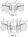
- FIG 1 a habitual arrangement in the prior art can be seen in which a perforated pipe (1) is inserted between a drain (2) and a conventional drainage siphon (3) in order to prevent the passage of gravel (4) though permitting drainage of the water collected by the waterproof fabric (13).
- Figure 2 represents the drainage siphon (5) of the invention, which incorporates a grooved housing (6) basically arranged as an extension of an exit (7), and which fits on the outside of the mouth (8) of a drain (2).
- the drain (2) is of the trap type, with just its base having been represented, once the habitual grating and skirting have been removed.
- the grooved housing (6) thus remains located between the mouth (8) and a depressed cavity (12).
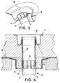
- FIG 3 a perspective view can be seen of the grooved housing (6) of the drainage siphon (5) of the invention, along with a lug (9), intended to support a hypothetical additional pipe (10), as shown in figure 4 .
- the functioning of the device as a whole is as follows. Most of the water evacuated via the drain (2) will circulate, either directly or via the additional pipe (10), as far as the drainage siphon (5). For its part, the water that does not reach the drain (2) will be led to a waterproof sheet (13) and, via a gravel fill (4), as far as the grooved housing (6) of the drainage siphon (5), given that the additional pipe (10), when incorporated, rests on the lug (9) and does not completely cover the grooves (11). See figures 2 and 4 .
- grooved housing (6) has been represented in which the grooves (11) are open in their upper part in order to facilitate the stripping of the drainage siphon (5) from its mould. It is evident that the shape and arrangement of the grooves (91) is irrelevant for the functionality of the invention. In the context of this document, grooved housing (6) will be understood as being any device with openings to permit the passage of water but not of gravel (4) through it.
Landscapes
- Engineering & Computer Science (AREA)
- Life Sciences & Earth Sciences (AREA)
- Health & Medical Sciences (AREA)
- Hydrology & Water Resources (AREA)
- Public Health (AREA)
- Water Supply & Treatment (AREA)
- Environmental & Geological Engineering (AREA)
- General Life Sciences & Earth Sciences (AREA)
- Mining & Mineral Resources (AREA)
- Paleontology (AREA)
- Civil Engineering (AREA)
- General Engineering & Computer Science (AREA)
- Structural Engineering (AREA)
- Jet Pumps And Other Pumps (AREA)
- Sink And Installation For Waste Water (AREA)
Abstract
Description
- The present invention relates to a drainage siphon intended to collect water coming from the overflowing of a drain and water collected by means of waterproof fabric, and to lead them to a drainage pipe. Its field of application is that of auxiliary materials for construction.
- Simple drainage siphons are known consisting of a central body that extends upwards in a perimetric flange and downwards in a central tubular exit intended to be inserted in a drainage pipe. The depth of the central body of the drainage siphon is normally sufficient for partially housing the drain inside itself, which ensures that the water can circulate.
- Nevertheless, the distance between the drain and the drainage siphon can sometimes be such that it becomes necessary to incorporate an appropriate means for ducting the water between the two elements, especially water coming from the overflowing of a drain and water collected by means of the waterproof fabric. The traditional solution consists of constructing a brickwork catchpit. This is slow, expensive and not secure, as well as being subject to deterioration with time. More recently, attempts have been made to replace the catchpit by laying waterproof fabric covered with gravel, with a perforated pipe being provided to prevent the gravel from passing through. This arrangement allows the circulation of the water overflowing from a drain and the water collected by means of the waterproof fabric. This solution is more secure and longer lasting, but it compels the use of a perforated pipe.
- It is consequently an objective of the present invention to provide a drainage siphon capable of receiving water coming from the overflowing of a drain and that collected by means of the waterproof fabric, without using special additional elements.
- In order to achieve the proposed objective, a drainage siphon has been conceived which incorporates a grooved housing in the interior of its central body such that this housing is able to receive a standard drainage pipe inside it, with the latter resting on at least one lug provided on the inner surface of the grooved housing.
- The grooved housing advantageously presents the form of a circular pipe which extends the lower exit of the drainage siphon upwards.
- Such a solution displays clear advantages. So:
- It solves the problem created by an excessive distance between drain and drainage siphon in a way that is economical, secure and lasting.
- For medium distances, it can be used without having to incorporate an additional drainage pipe between drain and drainage siphon, always provided that the height of the grooved housing is sufficient.
- In order to complement the foregoing description, and with the aim of aiding a better understanding of the characteristics of the invention, a detailed description is going to be given of a preferred embodiment, on the basis of a set of drawings attached to this descriptive specification and in which the following has been represented in an illustrative and non-limiting way.
-
Figure 1 shows an arrangement according to the prior art, which uses a perforated pipe. -
Figure 2 shows the solution proposed in the present invention, when the height of the grooved housing is sufficient so that the additional use of a drainage pipe becomes unnecessary. -
Figure 3 shows a cross-section in perspective of the inventive drainage siphon. -
Figure 4 shows the solution proposed in the present invention, when an additional drainage pipe needs to be used. - In the above figures, the numerical references correspond to the following parts and elements
- 1. Perforated pipe.
- 2. Drain.
- 3. Conventional drainage siphon.
- 4. Gravel.
- 5. Drainage siphon according to the invention.
- 6. Grooved housing of the drainage siphon.
- 7. Exit of the drainage siphon.
- 8. Mouth of the drain.
- 9. Lug.
- 10. Additional pipe.
- 11. Grooves.
- 12. Depressed cavity.
- 13. Waterproof fabric.
- In
figure 1 a habitual arrangement in the prior art can be seen in which a perforated pipe (1) is inserted between a drain (2) and a conventional drainage siphon (3) in order to prevent the passage of gravel (4) though permitting drainage of the water collected by the waterproof fabric (13). -
Figure 2 , on the other hand, represents the drainage siphon (5) of the invention, which incorporates a grooved housing (6) basically arranged as an extension of an exit (7), and which fits on the outside of the mouth (8) of a drain (2). In this particular case the drain (2) is of the trap type, with just its base having been represented, once the habitual grating and skirting have been removed. The grooved housing (6) thus remains located between the mouth (8) and a depressed cavity (12). - In
figure 3 a perspective view can be seen of the grooved housing (6) of the drainage siphon (5) of the invention, along with a lug (9), intended to support a hypothetical additional pipe (10), as shown infigure 4 . - The functioning of the device as a whole is as follows. Most of the water evacuated via the drain (2) will circulate, either directly or via the additional pipe (10), as far as the drainage siphon (5). For its part, the water that does not reach the drain (2) will be led to a waterproof sheet (13) and, via a gravel fill (4), as far as the grooved housing (6) of the drainage siphon (5), given that the additional pipe (10), when incorporated, rests on the lug (9) and does not completely cover the grooves (11). See
figures 2 and4 . - It will be evident to an expert in the field that there is a series of modifications and alternatives for adapting the invention to the chosen design and the means of production that are available. So, in the preferred embodiment, a single lug (9) has been represented, though a set of lugs could have been used or a perimetric step could even have been used on which the additional pipe would rest (10). Likewise, a grooved housing (6) has been represented in which the grooves (11) are open in their upper part in order to facilitate the stripping of the drainage siphon (5) from its mould. It is evident that the shape and arrangement of the grooves (91) is irrelevant for the functionality of the invention. In the context of this document, grooved housing (6) will be understood as being any device with openings to permit the passage of water but not of gravel (4) through it.
Claims (3)
- Improved drainage siphon (5) for drain (2), characterized by comprising a grooved housing (6) fitted to an exit mouth (8) of the drain (2) and, occasionally, to an additional pipe (10) for drainage, and a lug (9) provided so that the additional pipe (10) can rest on it, as the case might be.
- Improved drainage siphon (5) for drain (2), according to claim 1, characterized in that the grooved housing (6) comprises grooves (11) that are open in their upper part.
- Improved drainage siphon (5) for drain (2), according to claim 2, characterized in that the grooved housing (6) presents a circular cross-section,
Applications Claiming Priority (1)
| Application Number | Priority Date | Filing Date | Title |
|---|---|---|---|
| ES200930641U ES1071660Y (en) | 2009-11-12 | 2009-11-12 | PERFECTED BOILER FOR SINK |
Publications (2)
| Publication Number | Publication Date |
|---|---|
| EP2322725A1 true EP2322725A1 (en) | 2011-05-18 |
| EP2322725B1 EP2322725B1 (en) | 2012-05-16 |
Family
ID=41800359
Family Applications (1)
| Application Number | Title | Priority Date | Filing Date |
|---|---|---|---|
| EP10014443A Active EP2322725B1 (en) | 2009-11-12 | 2010-11-10 | Drainage siphon for drain |
Country Status (4)
| Country | Link |
|---|---|
| EP (1) | EP2322725B1 (en) |
| ES (1) | ES1071660Y (en) |
| PT (1) | PT2322725E (en) |
| ZA (1) | ZA201008085B (en) |
Cited By (3)
| Publication number | Priority date | Publication date | Assignee | Title |
|---|---|---|---|---|
| EP2620554A1 (en) * | 2012-01-19 | 2013-07-31 | Industrias Riuvert, S.A. | Securing device for impermeable fabrics in water evacuation systems |
| CN108867833A (en) * | 2018-08-28 | 2018-11-23 | 张兵 | A kind of siphon inspection well cover |
| EP3705655A1 (en) * | 2019-03-08 | 2020-09-09 | Viega Technology GmbH & Co. KG | Floor drain for removing water from a walkable floor into a sewer pipe |
Citations (4)
| Publication number | Priority date | Publication date | Assignee | Title |
|---|---|---|---|---|
| US20020136604A1 (en) * | 2001-03-22 | 2002-09-26 | Chris Sondrup | Adjustable height utility access device |
| US20040028470A1 (en) * | 2002-08-07 | 2004-02-12 | Guy Boudreau | Self-leveling system |
| US20060267336A1 (en) * | 2005-03-09 | 2006-11-30 | Peters John Jr | Step flange catch basin adaptor and method of using |
| DE202007006970U1 (en) * | 2007-05-15 | 2007-09-20 | Selfsan Consult Gmbh | Manhole cover with a monitoring device |
-
2009
- 2009-11-12 ES ES200930641U patent/ES1071660Y/en not_active Expired - Fee Related
-
2010
- 2010-11-10 PT PT10014443T patent/PT2322725E/en unknown
- 2010-11-10 EP EP10014443A patent/EP2322725B1/en active Active
- 2010-11-11 ZA ZA2010/08085A patent/ZA201008085B/en unknown
Patent Citations (4)
| Publication number | Priority date | Publication date | Assignee | Title |
|---|---|---|---|---|
| US20020136604A1 (en) * | 2001-03-22 | 2002-09-26 | Chris Sondrup | Adjustable height utility access device |
| US20040028470A1 (en) * | 2002-08-07 | 2004-02-12 | Guy Boudreau | Self-leveling system |
| US20060267336A1 (en) * | 2005-03-09 | 2006-11-30 | Peters John Jr | Step flange catch basin adaptor and method of using |
| DE202007006970U1 (en) * | 2007-05-15 | 2007-09-20 | Selfsan Consult Gmbh | Manhole cover with a monitoring device |
Cited By (4)
| Publication number | Priority date | Publication date | Assignee | Title |
|---|---|---|---|---|
| EP2620554A1 (en) * | 2012-01-19 | 2013-07-31 | Industrias Riuvert, S.A. | Securing device for impermeable fabrics in water evacuation systems |
| CN108867833A (en) * | 2018-08-28 | 2018-11-23 | 张兵 | A kind of siphon inspection well cover |
| EP3705655A1 (en) * | 2019-03-08 | 2020-09-09 | Viega Technology GmbH & Co. KG | Floor drain for removing water from a walkable floor into a sewer pipe |
| US11208795B2 (en) | 2019-03-08 | 2021-12-28 | Viega Technology Gmbh & Co. Kg | Floor drain for draining water from a walk-in floor into a sewage pipe |
Also Published As
| Publication number | Publication date |
|---|---|
| ES1071660U8 (en) | 2011-04-12 |
| ES1071660Y (en) | 2010-06-18 |
| EP2322725B1 (en) | 2012-05-16 |
| ZA201008085B (en) | 2012-04-25 |
| PT2322725E (en) | 2012-07-25 |
| ES1071660U (en) | 2010-03-24 |
Similar Documents
| Publication | Publication Date | Title |
|---|---|---|
| US9587851B2 (en) | Dehumidifier and float assembly thereof | |
| EP2322725A1 (en) | Drainage siphon for drain | |
| KR102075928B1 (en) | Apparatus to prevent overflow and intercept bad smellof drainage | |
| EP3215684B1 (en) | Drain assembly, drain body for use in such an assembly and odor trap of use in such an assembly | |
| PL359003A1 (en) | Cover piece for a drainage channel, and method for producing a drainage assembly | |
| KR200482899Y1 (en) | A draining trap | |
| JP2013221266A (en) | Toilet bowl device | |
| JP7041593B2 (en) | Deodorant one | |
| EP2206841B1 (en) | Siphon accessible to plumbing snake via feed opening | |
| EP2060682A3 (en) | Floor drain with removable odour seal | |
| KR101836793B1 (en) | Grating cover | |
| JP6496291B2 (en) | Water storage structure, water storage structure aggregate form, water collecting member | |
| JP2012102576A (en) | Remotely-operated drain plug system | |
| KR20110029745A (en) | Drain traps | |
| EP2884016A1 (en) | Drain with siphon | |
| CN211875226U (en) | Anti-overflow water faucet structure | |
| JP2019073950A (en) | Roof surface ventilation unit and construction method of roof surface ventilation unit | |
| CA2665085A1 (en) | Stair flower boxes | |
| KR200416033Y1 (en) | Flowerpot with a waterspout | |
| JP6427469B2 (en) | A low tank installed in the box of the simple flush type temporary toilet and a temporary toilet installed with the low tank | |
| JP5244336B2 (en) | Drain cover | |
| CN205369500U (en) | Prevent outside floor drain that discharges of peculiar smell | |
| KR20190000344U (en) | A flowerpot | |
| CN209760402U (en) | Floor drain pre-installation box and floor drain | |
| KR20130082225A (en) | The drain trap trench a stench intercept structure |
Legal Events
| Date | Code | Title | Description |
|---|---|---|---|
| PUAI | Public reference made under article 153(3) epc to a published international application that has entered the european phase |
Free format text: ORIGINAL CODE: 0009012 |
|
| AK | Designated contracting states |
Kind code of ref document: A1 Designated state(s): AL AT BE BG CH CY CZ DE DK EE ES FI FR GB GR HR HU IE IS IT LI LT LU LV MC MK MT NL NO PL PT RO RS SE SI SK SM TR |
|
| AX | Request for extension of the european patent |
Extension state: BA ME |
|
| 17P | Request for examination filed |
Effective date: 20110915 |
|
| GRAJ | Information related to disapproval of communication of intention to grant by the applicant or resumption of examination proceedings by the epo deleted |
Free format text: ORIGINAL CODE: EPIDOSDIGR1 |
|
| GRAP | Despatch of communication of intention to grant a patent |
Free format text: ORIGINAL CODE: EPIDOSNIGR1 |
|
| GRAP | Despatch of communication of intention to grant a patent |
Free format text: ORIGINAL CODE: EPIDOSNIGR1 |
|
| GRAS | Grant fee paid |
Free format text: ORIGINAL CODE: EPIDOSNIGR3 |
|
| GRAA | (expected) grant |
Free format text: ORIGINAL CODE: 0009210 |
|
| AK | Designated contracting states |
Kind code of ref document: B1 Designated state(s): AL AT BE BG CH CY CZ DE DK EE ES FI FR GB GR HR HU IE IS IT LI LT LU LV MC MK MT NL NO PL PT RO RS SE SI SK SM TR |
|
| REG | Reference to a national code |
Ref country code: GB Ref legal event code: FG4D |
|
| REG | Reference to a national code |
Ref country code: CH Ref legal event code: EP |
|
| REG | Reference to a national code |
Ref country code: AT Ref legal event code: REF Ref document number: 558169 Country of ref document: AT Kind code of ref document: T Effective date: 20120615 |
|
| REG | Reference to a national code |
Ref country code: IE Ref legal event code: FG4D |
|
| REG | Reference to a national code |
Ref country code: DE Ref legal event code: R096 Ref document number: 602010001542 Country of ref document: DE Effective date: 20120712 |
|
| REG | Reference to a national code |
Ref country code: PT Ref legal event code: SC4A Free format text: AVAILABILITY OF NATIONAL TRANSLATION Effective date: 20120717 |
|
| REG | Reference to a national code |
Ref country code: NL Ref legal event code: VDEP Effective date: 20120516 |
|
| REG | Reference to a national code |
Ref country code: LT Ref legal event code: MG4D Effective date: 20120516 |
|
| REG | Reference to a national code |
Ref country code: GR Ref legal event code: EP Ref document number: 20120401783 Country of ref document: GR Effective date: 20120920 |
|
| PG25 | Lapsed in a contracting state [announced via postgrant information from national office to epo] |
Ref country code: LT Free format text: LAPSE BECAUSE OF FAILURE TO SUBMIT A TRANSLATION OF THE DESCRIPTION OR TO PAY THE FEE WITHIN THE PRESCRIBED TIME-LIMIT Effective date: 20120516 Ref country code: CY Free format text: LAPSE BECAUSE OF FAILURE TO SUBMIT A TRANSLATION OF THE DESCRIPTION OR TO PAY THE FEE WITHIN THE PRESCRIBED TIME-LIMIT Effective date: 20120516 Ref country code: RS Free format text: LAPSE BECAUSE OF FAILURE TO SUBMIT A TRANSLATION OF THE DESCRIPTION OR TO PAY THE FEE WITHIN THE PRESCRIBED TIME-LIMIT Effective date: 20120516 Ref country code: IS Free format text: LAPSE BECAUSE OF FAILURE TO SUBMIT A TRANSLATION OF THE DESCRIPTION OR TO PAY THE FEE WITHIN THE PRESCRIBED TIME-LIMIT Effective date: 20120916 Ref country code: SE Free format text: LAPSE BECAUSE OF FAILURE TO SUBMIT A TRANSLATION OF THE DESCRIPTION OR TO PAY THE FEE WITHIN THE PRESCRIBED TIME-LIMIT Effective date: 20120516 Ref country code: NO Free format text: LAPSE BECAUSE OF FAILURE TO SUBMIT A TRANSLATION OF THE DESCRIPTION OR TO PAY THE FEE WITHIN THE PRESCRIBED TIME-LIMIT Effective date: 20120816 Ref country code: PL Free format text: LAPSE BECAUSE OF FAILURE TO SUBMIT A TRANSLATION OF THE DESCRIPTION OR TO PAY THE FEE WITHIN THE PRESCRIBED TIME-LIMIT Effective date: 20120516 Ref country code: FI Free format text: LAPSE BECAUSE OF FAILURE TO SUBMIT A TRANSLATION OF THE DESCRIPTION OR TO PAY THE FEE WITHIN THE PRESCRIBED TIME-LIMIT Effective date: 20120516 |
|
| REG | Reference to a national code |
Ref country code: AT Ref legal event code: MK05 Ref document number: 558169 Country of ref document: AT Kind code of ref document: T Effective date: 20120516 |
|
| PG25 | Lapsed in a contracting state [announced via postgrant information from national office to epo] |
Ref country code: SI Free format text: LAPSE BECAUSE OF FAILURE TO SUBMIT A TRANSLATION OF THE DESCRIPTION OR TO PAY THE FEE WITHIN THE PRESCRIBED TIME-LIMIT Effective date: 20120516 Ref country code: HR Free format text: LAPSE BECAUSE OF FAILURE TO SUBMIT A TRANSLATION OF THE DESCRIPTION OR TO PAY THE FEE WITHIN THE PRESCRIBED TIME-LIMIT Effective date: 20120516 Ref country code: LV Free format text: LAPSE BECAUSE OF FAILURE TO SUBMIT A TRANSLATION OF THE DESCRIPTION OR TO PAY THE FEE WITHIN THE PRESCRIBED TIME-LIMIT Effective date: 20120516 |
|
| PG25 | Lapsed in a contracting state [announced via postgrant information from national office to epo] |
Ref country code: BE Free format text: LAPSE BECAUSE OF FAILURE TO SUBMIT A TRANSLATION OF THE DESCRIPTION OR TO PAY THE FEE WITHIN THE PRESCRIBED TIME-LIMIT Effective date: 20120516 |
|
| PG25 | Lapsed in a contracting state [announced via postgrant information from national office to epo] |
Ref country code: NL Free format text: LAPSE BECAUSE OF FAILURE TO SUBMIT A TRANSLATION OF THE DESCRIPTION OR TO PAY THE FEE WITHIN THE PRESCRIBED TIME-LIMIT Effective date: 20120516 Ref country code: EE Free format text: LAPSE BECAUSE OF FAILURE TO SUBMIT A TRANSLATION OF THE DESCRIPTION OR TO PAY THE FEE WITHIN THE PRESCRIBED TIME-LIMIT Effective date: 20120516 Ref country code: SK Free format text: LAPSE BECAUSE OF FAILURE TO SUBMIT A TRANSLATION OF THE DESCRIPTION OR TO PAY THE FEE WITHIN THE PRESCRIBED TIME-LIMIT Effective date: 20120516 Ref country code: AT Free format text: LAPSE BECAUSE OF FAILURE TO SUBMIT A TRANSLATION OF THE DESCRIPTION OR TO PAY THE FEE WITHIN THE PRESCRIBED TIME-LIMIT Effective date: 20120516 Ref country code: CZ Free format text: LAPSE BECAUSE OF FAILURE TO SUBMIT A TRANSLATION OF THE DESCRIPTION OR TO PAY THE FEE WITHIN THE PRESCRIBED TIME-LIMIT Effective date: 20120516 Ref country code: DK Free format text: LAPSE BECAUSE OF FAILURE TO SUBMIT A TRANSLATION OF THE DESCRIPTION OR TO PAY THE FEE WITHIN THE PRESCRIBED TIME-LIMIT Effective date: 20120516 Ref country code: RO Free format text: LAPSE BECAUSE OF FAILURE TO SUBMIT A TRANSLATION OF THE DESCRIPTION OR TO PAY THE FEE WITHIN THE PRESCRIBED TIME-LIMIT Effective date: 20120516 |
|
| PLBE | No opposition filed within time limit |
Free format text: ORIGINAL CODE: 0009261 |
|
| STAA | Information on the status of an ep patent application or granted ep patent |
Free format text: STATUS: NO OPPOSITION FILED WITHIN TIME LIMIT |
|
| 26N | No opposition filed |
Effective date: 20130219 |
|
| PG25 | Lapsed in a contracting state [announced via postgrant information from national office to epo] |
Ref country code: ES Free format text: LAPSE BECAUSE OF FAILURE TO SUBMIT A TRANSLATION OF THE DESCRIPTION OR TO PAY THE FEE WITHIN THE PRESCRIBED TIME-LIMIT Effective date: 20120827 |
|
| REG | Reference to a national code |
Ref country code: DE Ref legal event code: R097 Ref document number: 602010001542 Country of ref document: DE Effective date: 20130219 |
|
| PG25 | Lapsed in a contracting state [announced via postgrant information from national office to epo] |
Ref country code: BG Free format text: LAPSE BECAUSE OF FAILURE TO SUBMIT A TRANSLATION OF THE DESCRIPTION OR TO PAY THE FEE WITHIN THE PRESCRIBED TIME-LIMIT Effective date: 20120816 |
|
| REG | Reference to a national code |
Ref country code: IE Ref legal event code: MM4A |
|
| REG | Reference to a national code |
Ref country code: DE Ref legal event code: R119 Ref document number: 602010001542 Country of ref document: DE Effective date: 20130601 |
|
| PG25 | Lapsed in a contracting state [announced via postgrant information from national office to epo] |
Ref country code: IE Free format text: LAPSE BECAUSE OF NON-PAYMENT OF DUE FEES Effective date: 20121110 Ref country code: DE Free format text: LAPSE BECAUSE OF NON-PAYMENT OF DUE FEES Effective date: 20130601 |
|
| PG25 | Lapsed in a contracting state [announced via postgrant information from national office to epo] |
Ref country code: MT Free format text: LAPSE BECAUSE OF FAILURE TO SUBMIT A TRANSLATION OF THE DESCRIPTION OR TO PAY THE FEE WITHIN THE PRESCRIBED TIME-LIMIT Effective date: 20120516 Ref country code: AL Free format text: LAPSE BECAUSE OF FAILURE TO SUBMIT A TRANSLATION OF THE DESCRIPTION OR TO PAY THE FEE WITHIN THE PRESCRIBED TIME-LIMIT Effective date: 20120516 |
|
| PG25 | Lapsed in a contracting state [announced via postgrant information from national office to epo] |
Ref country code: TR Free format text: LAPSE BECAUSE OF FAILURE TO SUBMIT A TRANSLATION OF THE DESCRIPTION OR TO PAY THE FEE WITHIN THE PRESCRIBED TIME-LIMIT Effective date: 20120516 Ref country code: MC Free format text: LAPSE BECAUSE OF NON-PAYMENT OF DUE FEES Effective date: 20121130 |
|
| PG25 | Lapsed in a contracting state [announced via postgrant information from national office to epo] |
Ref country code: LU Free format text: LAPSE BECAUSE OF NON-PAYMENT OF DUE FEES Effective date: 20121110 Ref country code: SM Free format text: LAPSE BECAUSE OF FAILURE TO SUBMIT A TRANSLATION OF THE DESCRIPTION OR TO PAY THE FEE WITHIN THE PRESCRIBED TIME-LIMIT Effective date: 20120516 |
|
| PG25 | Lapsed in a contracting state [announced via postgrant information from national office to epo] |
Ref country code: HU Free format text: LAPSE BECAUSE OF FAILURE TO SUBMIT A TRANSLATION OF THE DESCRIPTION OR TO PAY THE FEE WITHIN THE PRESCRIBED TIME-LIMIT Effective date: 20101110 |
|
| REG | Reference to a national code |
Ref country code: CH Ref legal event code: PL |
|
| PG25 | Lapsed in a contracting state [announced via postgrant information from national office to epo] |
Ref country code: LI Free format text: LAPSE BECAUSE OF NON-PAYMENT OF DUE FEES Effective date: 20141130 Ref country code: CH Free format text: LAPSE BECAUSE OF NON-PAYMENT OF DUE FEES Effective date: 20141130 Ref country code: MK Free format text: LAPSE BECAUSE OF FAILURE TO SUBMIT A TRANSLATION OF THE DESCRIPTION OR TO PAY THE FEE WITHIN THE PRESCRIBED TIME-LIMIT Effective date: 20120516 |
|
| REG | Reference to a national code |
Ref country code: PT Ref legal event code: PC4A Owner name: JIMTEN, S.A., ES Effective date: 20150805 |
|
| REG | Reference to a national code |
Ref country code: GB Ref legal event code: 732E Free format text: REGISTERED BETWEEN 20150813 AND 20150819 |
|
| REG | Reference to a national code |
Ref country code: FR Ref legal event code: PLFP Year of fee payment: 6 |
|
| REG | Reference to a national code |
Ref country code: FR Ref legal event code: TP Owner name: JIMTEN S.A., ES Effective date: 20151210 |
|
| REG | Reference to a national code |
Ref country code: FR Ref legal event code: PLFP Year of fee payment: 7 |
|
| REG | Reference to a national code |
Ref country code: FR Ref legal event code: PLFP Year of fee payment: 8 |
|
| REG | Reference to a national code |
Ref country code: FR Ref legal event code: PLFP Year of fee payment: 9 |
|
| PGFP | Annual fee paid to national office [announced via postgrant information from national office to epo] |
Ref country code: LU Payment date: 20181219 Year of fee payment: 15 |
|
| PG25 | Lapsed in a contracting state [announced via postgrant information from national office to epo] |
Ref country code: GR Free format text: LAPSE BECAUSE OF NON-PAYMENT OF DUE FEES Effective date: 20200609 |
|
| GBPC | Gb: european patent ceased through non-payment of renewal fee |
Effective date: 20191110 |
|
| PG25 | Lapsed in a contracting state [announced via postgrant information from national office to epo] |
Ref country code: GB Free format text: LAPSE BECAUSE OF NON-PAYMENT OF DUE FEES Effective date: 20191110 |
|
| P01 | Opt-out of the competence of the unified patent court (upc) registered |
Effective date: 20230523 |
|
| PGFP | Annual fee paid to national office [announced via postgrant information from national office to epo] |
Ref country code: PT Payment date: 20231009 Year of fee payment: 14 Ref country code: IT Payment date: 20231026 Year of fee payment: 14 Ref country code: FR Payment date: 20231011 Year of fee payment: 14 |