EP2322291A1 - Cleaning device adapted to eject high-pressure cleaning liquid - Google Patents
Cleaning device adapted to eject high-pressure cleaning liquid Download PDFInfo
- Publication number
- EP2322291A1 EP2322291A1 EP09808016A EP09808016A EP2322291A1 EP 2322291 A1 EP2322291 A1 EP 2322291A1 EP 09808016 A EP09808016 A EP 09808016A EP 09808016 A EP09808016 A EP 09808016A EP 2322291 A1 EP2322291 A1 EP 2322291A1
- Authority
- EP
- European Patent Office
- Prior art keywords
- holder
- washing liquid
- ejecting
- longitudinal direction
- pressure washing
- Prior art date
- Legal status (The legal status is an assumption and is not a legal conclusion. Google has not performed a legal analysis and makes no representation as to the accuracy of the status listed.)
- Granted
Links
Images








Classifications
-
- B—PERFORMING OPERATIONS; TRANSPORTING
- B08—CLEANING
- B08B—CLEANING IN GENERAL; PREVENTION OF FOULING IN GENERAL
- B08B3/00—Cleaning by methods involving the use or presence of liquid or steam
- B08B3/02—Cleaning by the force of jets or sprays
- B08B3/022—Cleaning travelling work
-
- B—PERFORMING OPERATIONS; TRANSPORTING
- B08—CLEANING
- B08B—CLEANING IN GENERAL; PREVENTION OF FOULING IN GENERAL
- B08B3/00—Cleaning by methods involving the use or presence of liquid or steam
- B08B3/02—Cleaning by the force of jets or sprays
-
- B—PERFORMING OPERATIONS; TRANSPORTING
- B05—SPRAYING OR ATOMISING IN GENERAL; APPLYING FLUENT MATERIALS TO SURFACES, IN GENERAL
- B05B—SPRAYING APPARATUS; ATOMISING APPARATUS; NOZZLES
- B05B1/00—Nozzles, spray heads or other outlets, with or without auxiliary devices such as valves, heating means
- B05B1/14—Nozzles, spray heads or other outlets, with or without auxiliary devices such as valves, heating means with multiple outlet openings; with strainers in or outside the outlet opening
- B05B1/20—Perforated pipes or troughs, e.g. spray booms; Outlet elements therefor
-
- B—PERFORMING OPERATIONS; TRANSPORTING
- B05—SPRAYING OR ATOMISING IN GENERAL; APPLYING FLUENT MATERIALS TO SURFACES, IN GENERAL
- B05B—SPRAYING APPARATUS; ATOMISING APPARATUS; NOZZLES
- B05B1/00—Nozzles, spray heads or other outlets, with or without auxiliary devices such as valves, heating means
- B05B1/14—Nozzles, spray heads or other outlets, with or without auxiliary devices such as valves, heating means with multiple outlet openings; with strainers in or outside the outlet opening
- B05B1/20—Perforated pipes or troughs, e.g. spray booms; Outlet elements therefor
- B05B1/202—Perforated pipes or troughs, e.g. spray booms; Outlet elements therefor comprising inserted outlet elements
-
- B—PERFORMING OPERATIONS; TRANSPORTING
- B05—SPRAYING OR ATOMISING IN GENERAL; APPLYING FLUENT MATERIALS TO SURFACES, IN GENERAL
- B05B—SPRAYING APPARATUS; ATOMISING APPARATUS; NOZZLES
- B05B13/00—Machines or plants for applying liquids or other fluent materials to surfaces of objects or other work by spraying, not covered by groups B05B1/00 - B05B11/00
- B05B13/02—Means for supporting work; Arrangement or mounting of spray heads; Adaptation or arrangement of means for feeding work
- B05B13/04—Means for supporting work; Arrangement or mounting of spray heads; Adaptation or arrangement of means for feeding work the spray heads being moved during spraying operation
- B05B13/0463—Installation or apparatus for applying liquid or other fluent material to moving work of indefinite length
- B05B13/0468—Installation or apparatus for applying liquid or other fluent material to moving work of indefinite length with reciprocating or oscillating spray heads
-
- G—PHYSICS
- G02—OPTICS
- G02F—OPTICAL DEVICES OR ARRANGEMENTS FOR THE CONTROL OF LIGHT BY MODIFICATION OF THE OPTICAL PROPERTIES OF THE MEDIA OF THE ELEMENTS INVOLVED THEREIN; NON-LINEAR OPTICS; FREQUENCY-CHANGING OF LIGHT; OPTICAL LOGIC ELEMENTS; OPTICAL ANALOGUE/DIGITAL CONVERTERS
- G02F1/00—Devices or arrangements for the control of the intensity, colour, phase, polarisation or direction of light arriving from an independent light source, e.g. switching, gating or modulating; Non-linear optics
- G02F1/01—Devices or arrangements for the control of the intensity, colour, phase, polarisation or direction of light arriving from an independent light source, e.g. switching, gating or modulating; Non-linear optics for the control of the intensity, phase, polarisation or colour
- G02F1/13—Devices or arrangements for the control of the intensity, colour, phase, polarisation or direction of light arriving from an independent light source, e.g. switching, gating or modulating; Non-linear optics for the control of the intensity, phase, polarisation or colour based on liquid crystals, e.g. single liquid crystal display cells
-
- H—ELECTRICITY
- H10—SEMICONDUCTOR DEVICES; ELECTRIC SOLID-STATE DEVICES NOT OTHERWISE PROVIDED FOR
- H10P—GENERIC PROCESSES OR APPARATUS FOR THE MANUFACTURE OR TREATMENT OF DEVICES COVERED BY CLASS H10
- H10P50/00—Etching of wafers, substrates or parts of devices
-
- H—ELECTRICITY
- H10—SEMICONDUCTOR DEVICES; ELECTRIC SOLID-STATE DEVICES NOT OTHERWISE PROVIDED FOR
- H10P—GENERIC PROCESSES OR APPARATUS FOR THE MANUFACTURE OR TREATMENT OF DEVICES COVERED BY CLASS H10
- H10P72/00—Handling or holding of wafers, substrates or devices during manufacture or treatment thereof
- H10P72/04—Apparatus for manufacture or treatment
- H10P72/0402—Apparatus for fluid treatment
- H10P72/0406—Apparatus for fluid treatment for cleaning followed by drying, rinsing, stripping, blasting or the like
- H10P72/0411—Apparatus for fluid treatment for cleaning followed by drying, rinsing, stripping, blasting or the like for wet cleaning or washing
- H10P72/0414—Apparatus for fluid treatment for cleaning followed by drying, rinsing, stripping, blasting or the like for wet cleaning or washing using mainly spraying means, e.g. nozzles
Definitions
- the present invention generally relates to a high-pressure washing liquid ejecting washing apparatus (also referred to as a water jet washing machine) which ejects a high-pressure washing liquid to flat plate materials such as FPDs (flat panel displays), for example, liquid crystal panels, plasma panels, solar panels, or organic EL (electro luminance) panels, large-sized plate glasses, or semiconductor wafers, and washes them.
- FPDs flat panel displays
- the present invention relates to a high-pressure washing liquid ejecting washing apparatus which is used to eject a high-pressure washing liquid (including high-pressure water) to remove contaminants which cause a low yield, such as fine particles, organic matters, metal impurities on glass substrate surfaces in manufacturing steps of the liquid crystal displays or the semiconductor wafers, has a simple structure and achieves a cost reduction.
- a high-pressure washing liquid including high-pressure water
- nozzles used in the conventional washing apparatus are cone-type nozzles ejecting a washing liquid spreading in a conical shape or fan-type nozzles ejecting a washing liquid spreading in a sector shape.
- cone-type nozzles ejecting a washing liquid spreading in a conical shape
- fan-type nozzles ejecting a washing liquid spreading in a sector shape.
- the washing apparatus in the above publication uses the convergent ejecting nozzles ejecting the washing liquid in a single straight-line shape without diffusing, and therefore, an energy density of the ejected washing liquid is very high and is several tens times as high as that of the cone-type nozzles or the fan-type nozzles. This can remove the contaminants on the washed surface and wash the objects very effectively.
- regions (areas) of the objects to which the washing liquid is applied are very small, and only localized regions are washed. In other words, regions to which the washing water is not applied are large and these regions cannot be washed.
- the present inventors discovered a high-pressure washing liquid ejecting washing method and apparatus in which a plurality of high-pressure washing liquid ejecting nozzles eject a washing liquid in a single straight-line shape to the objects to wash them, while moving the objects at a constant speed, the high-pressure washing liquid ejecting nozzles are arranged on a common holder to be spaced apart from each other and are oriented in the same direction so as to face the objects, and the high-pressure washing liquid ejecting nozzles are rotated integrally with the holder to eject the high-pressure washing liquid to the objects and filed a patent application (Japanese Patent Application No. 2007-281322 ).
- a washing apparatus including a detector means for detecting specified regions attached with more contaminants than those of other regions within surfaces of the objects, a retaining means for retaining the objects in a tilted state along a direction in which the objects are conveyed, a conveyor means for conveying the objects retained by the retaining means in the conveying direction, a discharge means for discharging a washing liquid to the surfaces of the objects, and a moving means for moving the discharge means along a width direction of the objects which is orthogonal to the conveying direction, within the surface of the object, and the discharge means selectively discharges the washing liquid to the specified regions (see for example, Japanese Laid-Open Patent Application Publication No. 2006-10947 ).
- the washing density increases as a rotational speed for rotating the holder in a circular shape is increased, but the holder or the overall apparatus including the holder vibrates growingly. This vibration acceleration increases with a square of the rotational speed. Therefore, in a hand-held washing apparatus disclosed in Patent No. 2705719 , it is difficult for an operator to continue a washing operation while holding the washing apparatus with hands. If the number of nozzles attached on the holder is made twice or three times more, an overall length of the holder increases, and an outer diameter of the holder increases significantly. This is unsuitable as the hand-held washing apparatus.
- the apparatus disclosed in Japanese Laid-Open Patent Application Publication No. 2006-10947 is adapted to intensively wash the specified regions of the objects which are attached with more contaminants and not to wash the entire objects uniformly.
- a washing apparatus 70 disclosed in the above previous application has a configuration in which a holder 71 attached with a plurality of high-pressure water ejecting nozzles 72 are rotated in a circular shape within a horizontal plane by eccentric rotation of drive shafts 74 at both sides of the holder 71 to carry out washing, as shown in Fig. 12 .
- a bending moment of an isosceles triangle shape acts on the holder 71 by a force in Y-direction in Fig. 12 . Therefore, the holder 71 needs to have a cross-sectional stiffness to withstand the bending moment.
- the apparatus increases in size and weight.
- eccentric rotation drive units 73 and drive motors at both sides must be enhanced in performance, causing a high cost and an increased vibration to outside things.
- a seal structure is complex.
- the present invention has been developed under the circumstances, and an object of the present invention is to provide a high-pressure washing liquid ejecting washing apparatus which is simpler in structure than the washing apparatus of the previous application, and achieves reduction of a size, a weight, and a cost, suppress a vibration of the apparatus during washing, and enables uniform and efficient washing.
- a high-pressure washing liquid ejecting washing apparatus of the present invention comprises a bar-shaped holder; and a plurality of high-pressure washing liquid ejecting nozzles arranged at constant intervals along a longitudinal direction of the bar-shaped holder, the holder being supported at both sides in a longitudinal direction thereof such that the holder is rotatable around its longitudinal axis, the holder being reciprocatingly rotated around the longitudinal axis within a predetermined rotational angle and the ejecting nozzles ejecting a high-pressure washing liquid to a washed surface of an object in a single straight-line shape to wash the object while the object is conveyed at a constant speed with respect to the holder, wherein the holder has a length which is not less than a length across the object and is disposed such that the holder is orthogonal to a direction in which the object is conveyed or is tilted with respect to the direction in which the object is conveyed, when viewed from a normal
- the plurality of high-pressure washing liquid ejecting nozzles perform a reciprocating rotational movement (rotational movement occurring clockwise and counterclockwise alternately in repetition) within a predetermined rotational angle around the longitudinal axis of the holder, along with the holder, and the plurality of ejecting nozzles eject the high-pressure washing liquid in a straight-line shape. Therefore, a high washing ability is obtained.
- the holder reciprocatingly rotates with the predetermined rotational angle in the direction orthogonal to the longitudinal direction of the holder and the high-pressure washing liquid is ejected uniformly to the substantially entire object over a width direction. Thus, washing unevenness is less likely to occur.
- a movement speed of the object is increased, a reciprocating rotation time is reduced, or a reciprocating rotational angle is reduced to achieve high-speed washing, a vibration acceleration of the holder or the overall apparatus including the holder does not increase and a vibration is suppressed.
- the ejecting nozzles may be arranged along the longitudinal direction of the holder on a lower surface of the holder; the holder may be provided with a high-pressure washing liquid feed passage which extends along the longitudinal direction of the holder in a straight-line shape and communicates with the ejecting nozzles; one end of a flexible high-pressure washing liquid feed pipe may be coupled to an end portion of the high-pressure washing liquid feed passage; and rotary shafts may be attached to longitudinal both end surfaces of the holder such that the rotary shafts are rotatable integrally with the holder.
- the rotary shafts at the both sides of the holder are rotatably supported by, for example, bearings, and a reciprocating rotational force is given to the holder via a crank mechanism, a motor, etc to reciprocatingly rotate it.
- the holder is pivoted around the axis with a pivot range (rotational angle ⁇ ) which is as small as about 10 degrees to 30 degrees. Therefore, the flexible high-pressure washing liquid feed pipe is bent to absorb a displacement of the end portion of the holder during the pivot movement of the holder.
- the high-pressure washing liquid supplied to the high-pressure washing liquid feed passage through the high-pressure washing liquid feed pipe is ejected substantially uniformly from the ejecting nozzles facing (communicating with) the high-pressure washing liquid feed passage.
- the holder may be a block body having a rectangular cross-section in a direction orthogonal to the longitudinal direction of the holder, tubular members with a rectangular cross-section which open toward the holder may be provided integrally with one end portions of the rotary shafts, both end portions of the block body may be fittingly inserted into the tubular members, respectively, and each of the end portions of the block body may be fastened integrally to the tubular member by a bolt penetrating the end portion of the block body and the tubular member.
- the holder formed by the block body is surely attached integrally to the rotary shaft and it is possible to prevent the bolt from coming loose and the rotary shaft from disengaging from the holder inadvertently.
- the holder may be supported at both sides thereof such that the holder is rotatable around the longitudinal axis and is movable along the longitudinal direction.
- the holder may be disposed to extend in a direction orthogonal to the direction in which the object is conveyed.
- the holder may be reciprocatingly rotatable around the longitudinal axis within a predetermined rotational angle and is reciprocatingly movable within a predetermined dimension in the longitudinal direction.
- the holder is rotated (pivoted) along the longitudinal axis and performs a reciprocating movement (reciprocating movement in a straight line direction) in the longitudinal direction (long axis) of the holder while the washing liquid is ejected under a high-pressure from a plurality of ejecting nozzles.
- the holder may be disposed to extend in the direction orthogonal to the direction in which the object is conveyed. In other words, it is not necessary to tilt the holder with respect to the direction in which the object is conveyed. This reduces a space in which the holder is installed.
- a common motor may give a rotational force to the rotary shafts of the holder to reciprocatingly rotate the rotary shafts around the longitudinal axis while permitting a reciprocating movement of the rotary shafts in the longitudinal direction, and may give a force (reciprocating driving force in a straight line direction) to the rotary shafts of the holder to cause the rotary shaft to perform a reciprocating linear movement in the longitudinal direction while permitting a rotation of the rotary shafts around the longitudinal direction.
- the holder performs a reciprocating movement smoothly in a straight-line shape at constant pitches in the longitudinal direction while pivoting the holder around the longitudinal axis. Therefore, the high-pressure washing liquid is ejected to the object so as to draw a desired oval shape as well as a circular shape to wash it, and washing uniformity is ensured flexibly.
- the common motor causes the holder to perform the pivot movement and the reciprocating movement in the longitudinal direction concurrently. Thus, two operations can occur in synchronization with a simple structure.
- a reciprocating rotation stroke distance of the holder around the longitudinal axis may be equal to a reciprocating stroke distance of the holder in the longitudinal direction.
- the washing liquid can be ejected to the object so as to draw a perfect circle shape.
- the high-pressure washing liquid ejecting washing apparatus of the present invention has a simpler structure than the high-pressure washing liquid ejecting washing apparatus of a previous application, and achieves substantially the same washing action as that of the high-pressure washing liquid ejecting washing apparatus of the previous application.
- An acceleration of the holder in the forward and backward direction is balanced more easily than that of the washing apparatus of the previous application. Therefore, the washing liquid ejecting washing apparatus of the present invention is handled easily.
- the high-pressure washing liquid ejecting washing apparatus of the present invention has the above configuration and achieves the following advantageous effects.
- a plurality of ejecting nozzles reciprocatingly rotate within a predetermined angle range around the longitudinal axis along with the holder. During this rotation, the plurality of ejecting nozzles eject the washing liquid to the object under a high-pressure.
- the holder is reciprocatingly pivoted around the longitudinal axis, the holder is tilted (e.g., tilting angle of 10 degrees to 20 degrees) with respect to the direction in which the object is conveyed, as shown in Fig. 1A , thereby forming a washing trajectory with a zigzag shape (bellows shape) as shown in Fig.
- a washing region with a constant width is formed over a width (direction orthogonal to the direction in which the object is conveyed) of the object. Since the object is conveyed at a constant speed to get across the washing region, the washing liquid is ejected to the entire surface of the object uniformly and with a high washing density under a high-pressure, a high washing ability is obtained and washing unevenness is less likely to be generated. Since the holder is pivoted around the axis to perform washing, a vibration acceleration is not increased and a vibration is suppressed even if a high-speed operation is achieved. Thus, a washing effect with a high washing density is obtained.
- the washing apparatus of the present invention can reduce stiffness of the holder, reduce a weight of a rotation support structure such as bearings, reduce a vibration, and significantly reduce a manufacturing cost, as compared to the washing apparatus of the previous application in which the holder is rotated within a horizontal plane.
- the washing apparatus of the present invention is installed within a washing room closed, called a clean room, without a need to a provide a gap (between holder support portion 75 and washing room side wall 77) shown in Fig. 12 , and therefore a seal mechanism is simplified.
- the washing liquid is ejected to the object so as to draw a perfect circle shape or an oval shape and wash it, a washing performance which is substantially as high as that of the washing apparatus of the previous application is attained, a structure is simple and a significant cost reduction is achieved as compared the washing apparatus of the previous application.
- a timing of the reciprocating linear movement of the holder and a stroke distance of the holder a washing trajectory with a desired oval shape as well as a washing trajectory with a perfect circle shape is drawn. As a result, washing uniformity is achieved with higher flexibility.
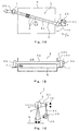
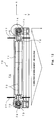
- Fig. 1A is a plan view of a high-pressure washing liquid ejecting washing apparatus 1 according to Embodiment 1 of the present invention.
- Fig. 1B is a front view of the high-pressure washing liquid ejecting washing apparatus 1 of Fig. 1A.
- Fig. 1C is a view taken in the direction of arrows along A of Fig. 11A .
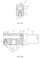
- Fig. 2A is a cross-sectional view of a holder 2 of the high-pressure washing liquid ejecting washing apparatus 1 of Fig. 1A .
- the high-pressure washing liquid ejecting washing apparatus 1 is a swingable (pivotable or reciprocatingly rotatable) washing apparatus, and includes a holder 2 with a circular cross-section.
- the holder 2 has a structure in which a block-like nozzle unit 4 which is open at a lower end 4a is integrally attached by welding to a lower surface of a cylindrical pipe body 2a in a longitudinal direction and a plurality of high-pressure washing liquid ejecting nozzles 3 are arranged within the nozzle unit 4 to be spaced apart from each other.
- the high-pressure washing liquid ejecting washing apparatus 1 is configured in such a manner that the holder 2 is tilted at about an angle a with respect to a width direction of a rectangular object x and a length of the holder body 2a is not less than a length (length in width direction) across the object x, when viewed from above in a normal line direction of a washed surface of the object x.
- the holder 2 is disposed such that its longitudinal both ends protrude from the object x when viewed from above.
- rotary shafts 2b are supported by bearing devices 7, respectively such that they are rotatable around a longitudinal axis of the holder 2.
- Each bearing device 7 is formed by a support base including a bearing.
- the body 2a is disposed inside the washing room 10, and the rotary shafts 2b protrude outward through side walls 10b of the washing room 10 extending vertically.
- An opening space 10c is formed on each side wall 10b through which the rotary shaft 2b protrudes outward, and a ring-shaped seal is which is not shown is mounted in a gap between the opening space 10c and the rotary shaft 2b.
- the holder 2 is reciprocatingly rotatable within a predetermined rotational angle ⁇ around its longitudinal axis by a piston and crank mechanism.
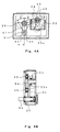
- a lever 21 is attached to the rotary shaft 2b by a sleeve-like rotation transmission member 27 such that the lever 21 is rotatable integrally with the rotary shaft 2b.
- a crank 23 rotatable in one direction (e.g., clockwise) by a servo motor 22 is coupled to an opposite end of the lever 21 via a connecting rod 24 such that the crank 23 and the lever 21 are rotatable by a crank pin 25 and a piston pin 26.
- a counterweight 23a is provided integrally at an opposite end side (opposite side of the crank pin 25) of the crank 23.
- the piston pin 26 of the lever 21 reciprocatingly rotates by ⁇ (e.g., 30 degrees) around the rotary shaft 2b to reciprocatingly rotate the rotary shaft 2b around a center location S.
- the holder 2 reciprocatingly rotates by the rotational angle ⁇ around its longitudinal axis and pivoted, so that a washing liquid is ejected under a high-pressure from respective ejecting nozzles 3 on the lower surface of the holder 2 to surfaces of the objects x.
- the ejecting nozzles 3 are designed to reciprocatingly rotate by ⁇ 1 of 30 degrees around the rotational center S of the holder 2.
- a rotation radius of the crank 23 is r1 and a rotation radius of the lever 21 is R1.
- a pivot stroke of the lever 2 is S1.
- a rotational angle ⁇ 2 and a pivot stroke S2 can be made smaller than ⁇ 1 and S1, respectively by reducing the rotation radius of the crank 23 from, for example, r1 to r2, as shown in Fig. 5B .
- a rotational angle ⁇ 3 is smaller than ⁇ 1.
- the washing liquid (including washing water) ejected from each ejecting nozzle 3 is ejected in a single straight-line shape under a high-pressure.
- the washing liquid of the single straight-line shape, which is ejected from the ejecting nozzle 3, has a higher washing ability (washing force).
- the washing liquid ejected from each ejecting nozzle 3 is a single straight-line shape
- the holder 2 is pivoted around its longitudinal axis in a state where the holder 2 is slightly tilted with respect to the width direction of the object x, and the object x is conveyed at a predetermined speed by a conveyor mechanism (not shown) such as a roller conveyor. Therefore, by adjusting the speeds of the holder 2 and the object x, the substantially entire surface of the object x can be washed.
- Fig. 2B is a cross-sectional view of the holder 2 according to modification example 1.
- Fig. 2C is a perspective view schematically showing an external appearance of the entire holder of Fig. 2B .
- the body 2a of the holder 2 is formed by a bar-like block body 31 of a tube shape with a rectangular cross-section.
- the block body 31 has at a center axis portion thereof a high-pressure washing liquid feed passage 32 with a rectangular cross-section, extending along a longitudinal direction thereof.
- the block body 31 has a plurality of through-holes 33 formed vertically at locations between which the high-pressure washing liquid feed passage 32 is interposed, at longitudinal both end portions or at locations spaced apart from each other in the longitudinal direction thereof.
- the nozzle unit 4 is integrally fastened to the lower surface of the body 2a by bolts 8 with heads 8a, and is formed by a block body having a tube shape with a rectangular cross-section and the open lower end 4c and extending continuously in the longitudinal direction.
- the nozzle unit 4 has threaded holes 40 into which threaded portions 8b of the bolts 8 are threaded, with the ejecting nozzle 3 interposed between them.
- the holder 2 is coupled by large-sized bolts.
- a washing liquid feed pipe 9 such as a high-pressure hose formed of flexible metal or flexible rubber and reinforced by winding a metal blade (wire) around its outer peripheral surface is coupled to one end portion of the high-pressure washing liquid feed passage 32.
- Fig. 2D shows modification example 2 of the holder 2.
- the holder 2 of Fig. 2D is basically identical to that of Fig. 2B and is different from the same in that a size and a weight are reduced in the holder 2 of Fig. 2D .
- the holder 2 of Fig. 2D is different in that since the high-pressure washing liquid feed passage 32 has a smaller cross-sectional area, the washing liquid feed pipe 9 is coupled to each of both end portions of the high-pressure washing liquid feed passage 32.
- the holder 2 of Fig. 2D is different in that since a cylindrical potion 4b below the cylindrical portion 4a is larger in outer diameter than the cylindrical portion 4a of the nozzle unit 4 to which the ejecting nozzle 3 is mounted.
- Figs. 3A ⁇ 3C are cross-sectional views showing modification example 3 of the holder 2.
- the body 2a is formed of a block body of a tube shape with a rectangular cross-section.
- the body 2a is integral with the nozzle unit 4, and is provided with the high-pressure washing liquid feed passage 32 with a circular cross-section extending along the longitudinal direction.
- the holder 2 is provided with the rotary shafts 2b at both sides of the body 2a such that the rotary shaft 2b are rotatable integrally with the body 2a.
- Fig. 3A is formed of a block body of a tube shape with a rectangular cross-section.
- the body 2a is integral with the nozzle unit 4, and is provided with the high-pressure washing liquid feed passage 32 with a circular cross-section extending along the longitudinal direction.
- the holder 2 is provided with the rotary shafts 2b at both sides of the body 2a such that the rotary shaft 2b are rotatable integrally with the body 2a.
- a horse-shoe portion 2c is provided integrally at one end portion of the rotary shaft 2b such that the horse-shoe portion 2c opens in a portion facing the body 2a and opens in upper and lower sides.
- the body 2a and the both side portions of the nozzle unit 4a are fittingly inserted into the horse-shoe portions 2c of the respective rotary shafts 2b.
- a through-hole 5 is formed through the end portion of the horse-shoe portion 2c and the end portion of the nozzle unit 4 to penetrate laterally, as shown in Figs. 3B and 3C .
- the rotary shaft 2b is provided with a cylindrical protrusion 2d which is fitted into the high-pressure washing liquid feed passage 32.
- the protrusion 2d is fitted into the end portion of the high-pressure washing liquid feed passage 32 in a state where an O-ring 34 is fitted around the protrusion 2d, thereby sealing it.
- a connecting hole 4d is formed at the end portion of the nozzle unit 4 to connect the high-pressure washing liquid feed pipe 9 such that the connecting hole 4d faces the high-pressure washing liquid feed passage 32.
- one end of the metal-made feed pipe 9 which is flexible is connected to the high-pressure washing liquid feed passage 32.
- the opposite end of the metal-made feed pipe 9 is connected to a high-pressure washing liquid pump (not shown).
- the high-pressure washing liquid pump feeds the high-pressure washing liquid to the respective ejecting nozzles 3 of the nozzle unit 4 through the metal-made feed pipe 9, and then through the high-pressure water feed passage 32 of the holder 2 which is connected at one end to the pipe 9.
- the high-pressure water is ejected from the each of the ejecting nozzles 3 in a single straight-line shape.
- the metal-made high-pressure washing liquid feed pipe 9 may be, for example, entirely gently curved so long as it is flexible.
- Figs. 9B - 9D show modification examples 1 - 3 of the washing liquid feed pipe 9.
- Fig. 9B shows a washing liquid feed pipe 9' formed by a high-pressure hose
- Fig. 9C shows a state where a spiral metal-made washing liquid feed pipe 9" is coupled.
- Fig. 9D shows a state where one end of a fixed washing liquid feed pipe 11 with high stiffness is coupled to the end portion of the rotary shaft 2b via a swivel joint 12.
- a downstream side of the high-pressure pump is coupled to a tank storing washing liquid or washing water.
- Fig. 6B shows a trajectory of the washing liquid ejected from the ejecting nozzle 3 of the holder 2 onto the object x.
- a pivot movement speed of the ejecting nozzle 3 is zero. Therefore, at the direction changing location B, an ejecting time of the washing liquid with respect to the object x is longer than that of other region. Generally, when the ejecting time increases, the washing ability is enhanced, causing washing unevenness. However, in the washing apparatus of the present invention, its influence is lessened. As shown in Fig.
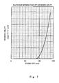
- Fig. 7 is a graph showing a relationship between the distance (stand-off) from the ejecting nozzle 3 to the object x and the washing ability, and depicting a relationship between a time for the washing liquid is ejected through an aluminum foil and a distance. As can be seen, the washing ability reduces when the distance increases from 100mm of L to 108mm of LA.
- the holder 2 is pivoted (reciprocatingly rotated) around its axis while ejecting the washing liquid in a single straight-line shape from the respective ejecting nozzles 3 under a high-pressure in a state where the holder 2 is tilted at an angle ⁇ with respect to a conveying direction (arrow) of the object x.
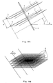
- the washing liquid ejected from the ejecting nozzles 3 arranged with nozzle pitches P on the lower surface of the holder 2 is swung, thereby forming a continuous zigzag-shaped washing trajectory J as shown in Fig. 8A.
- Fig. 8B shows trajectories (zigzag patterns) of the high-pressure washing liquid ejected from the four ejecting nozzles 3.
- the object x conveyed in the arrow direction moves across a washing region K formed by superposing the trajectories of the high-pressure washing liquid ejected from the four ejecting nozzles 3 arranged with nozzle pitches P, as shown in Fig. 8B .
- the substantially entire surface of the object x is washed with the washing liquid.
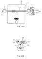
- Fig. 10A is a plan view of a high-pressure washing liquid ejecting washing apparatus according to Embodiment 2 of the present invention.
- Fig. 10b is a front view schematically showing a drive mechanism of Fig. 10A .
- a washing apparatus 1' of this embodiment is capable of ejecting the washing liquid from the ejecting nozzles 3 to the object x so as to draw a circle shape or an oval shape by adding a horizontal linear movement of the holder 2 in the longitudinal direction to the swingable washing apparatus 1. Therefore, as shown in Fig. 10A , the holder 2 can be disposed in a direction orthogonal to the conveying direction of the object x when viewed from above.
- a transmission member 42 serves to transmit a rotational force of a servo motor 41 to the rotary shaft 2b and is coupled to the rotary shaft 2b so as to permit the rotary shaft 2b to perform a reciprocating movement in the longitudinal direction.
- bearings 7' at both sides of the holder 2 support the holder 2 such that the holder 2 is rotatable around its longitudinal axis and support the holder 2 such that the holder 2 is movable in the longitudinal direction thereof.
- a drive mechanism 43 for providing a reciprocating linear movement to each of the rotary shafts 2b of the holder 2 at constant pitches in the longitudinal direction converts a rotational force of the servo motor 44 in one direction into a reciprocating driving force of the holder 2 in the longitudinal direction, and applies a linear force (reciprocating driving force in a straight-line direction) to the rotary shaft 2b for reciprocating movement.
- a transmission member 45 for transmitting the linear force of the drive mechanism 43 to the rotary shaft 2b is coupled to the rotary shaft 2b so as to permit its rotation.
- the washing apparatus 1' of this embodiment pivots the holder 2 around its longitudinal axis and reciprocate the holder 2 in the longitudinal direction while ejecting the washing liquid from a plurality of ejecting nozzles 3 under a high-pressure.
- the washing liquid is ejected to draw a perfect circle shape or an oval shape. Therefore, the washing liquid is ejected to the entire object x uniformly to effectively wash the object x with a high washing density.
- there is a time lag between the direction changing location B see Figs.
- the washing liquid is not intensively ejected onto a specified region on the object x.
- a pivot stroke distance of the holder 2 can conform to a reciprocating movement stroke distance of the holder 2 in the longitudinal direction.
- the washing liquid is ejected onto the object x to draw a perfect circle shape. By adjusting these stroke distances, the washing liquid can be ejected to draw a desired oval shape as well as the perfect circle shape. Thus, uniformity of washing is ensured with flexibility.
- the other constituents are identical to those of the high-pressure washing liquid ejecting washing apparatus 1 of Embodiment 1. They are designated by the same reference symbols and will not be described repetitively.
- the high-pressure washing liquid ejecting washing apparatus 1' has a simpler structure than the washing apparatus of a previous application and provides a washing action similar to that of the washing apparatus of the previous application. An acceleration of the holder in the forward and backward direction is balanced more easily than that of the washing apparatus of the previous application. Therefore, the high-pressure washing liquid ejecting washing apparatus 1' is handled easily.
- Figs. 11A ⁇ 11F are views showing a modification example of the drive mechanism of the high-pressure washing liquid ejecting washing apparatus 1' in detail.
- a drive mechanism 50 of this example is configured in such a manner that a common motor 61 causes the holder 2 to perform a reciprocating pivot movement around its longitudinal direction and a linear reciprocating movement in the longitudinal direction via gear mechanisms 62, 63, by piston and crank mechanism 51, 52.
- the rotary shaft 2b is capable of a reciprocating linear movement in the longitudinal direction thereof by a spline mechanism 53 provided at one end portion thereof.
- a spline mechanism 53 provided at one end portion thereof.
- the small-diameter support rod 2e is rotatably integrally coupled to one end portion of the rotary shaft 2b.
- the rotation coupling member 54 is inserted with a slack into a horse-shoe-shaped cover 55 having an open end.
- the rotation coupling member 54 is coupled to the horse-shoe-shaped cover 55 such that they are bendable around a pivot 55a via the pivot 55a and a bearing 55b.
- an opposite end center portion of the horse-shoe-shaped cover 55 is coupled to a piston member 65a of the piston crank mechanism 52 by a connecting rod 56. Therefore, the outer tube 53a reciprocatingly rotates by a predetermined angle ⁇ around the rotary shaft 2b while permitting a reciprocating movement of the rotary shaft 2b in the longitudinal direction by the spline mechanism 53.
- the outer tube 53a is rotatably mounted to a casing of an apparatus body via the bearing 53b.
- the rotation of the motor 61 is speed-reduced via the gear mechanism 62 (gear 62a, gear 62b) and is transmitted to a first rotation driving shaft 67, which rotates.
- One end of the crank 68 is coupled to a tip end of the rotation driving shaft 67 via a bearing 68a such that the crank 68 is rotatable around the axis, while a piston member 68b at an opposite end of the crank 68 is pivotally coupled to one end of the lever 69.
- An opposite end of the lever 69 is coupled to the outer tube 54 such that the lever 69 is rotatable integrally with the outer tube 54.
- a second rotation driving shaft 60 is disposed to extend in a direction orthogonal to the first rotation driving shaft 67.
- the rotation of the first rotation driving shaft 67 is transmitted via bevel gears 63a, 63b to the second rotation driving shaft 60, which rotates simultaneously with the rotation of the first rotation driving shaft 67.
- a third rotation driving shaft 64 is disposed to extend in parallel with the second rotation driving shaft 60.
- the rotation of the second rotation driving shaft 60 is transmitted to the third rotation driving shaft 64 via the gears 60a, 64a.
- a pivot movement of the connecting rod 56 by the crank 65 at the piston member 65a side is absorbed by a bending movement of an opposite end side of the connecting rod 56 around the pivot 55a of the rotation coupling member 54.
- the first rotation driving shaft 67 is disposed in parallel with the connecting rod 56.
- the linear reciprocating movement of the holder 2 in the longitudinal direction by the rotation coupling member 54 is permitted by the spline mechanism 53 and the pivot movement of the outer tube 53a is not impeded.
- the pivot movement of the rotation coupling member 54 is permitted by the bearing 54a ( Fig. 11F ) and therefore the linear reciprocating movement of the rotary shaft 2b is not impeded.
- the holder 2 is capable of the reciprocating pivot movement around the axis of the rotary shaft 2b and the reciprocating linear movement in the longitudinal direction concurrently, according to a rotation of a common (single) motor 61.
- ejecting nozzles 3 are aligned at constant intervals on the lower surface of the holder 2, they may be arranged in two or three rows in zigzag shape at equal intervals.
Landscapes
- Physics & Mathematics (AREA)
- Nonlinear Science (AREA)
- Chemical & Material Sciences (AREA)
- Crystallography & Structural Chemistry (AREA)
- General Physics & Mathematics (AREA)
- Optics & Photonics (AREA)
- Cleaning By Liquid Or Steam (AREA)
- Liquid Crystal (AREA)
- Nozzles (AREA)
- Cleaning Or Drying Semiconductors (AREA)
Abstract


Description
- The present invention generally relates to a high-pressure washing liquid ejecting washing apparatus (also referred to as a water jet washing machine) which ejects a high-pressure washing liquid to flat plate materials such as FPDs (flat panel displays), for example, liquid crystal panels, plasma panels, solar panels, or organic EL (electro luminance) panels, large-sized plate glasses, or semiconductor wafers, and washes them. More specifically, the present invention relates to a high-pressure washing liquid ejecting washing apparatus which is used to eject a high-pressure washing liquid (including high-pressure water) to remove contaminants which cause a low yield, such as fine particles, organic matters, metal impurities on glass substrate surfaces in manufacturing steps of the liquid crystal displays or the semiconductor wafers, has a simple structure and achieves a cost reduction.
- As the above high-pressure washing liquid ejecting washing apparatus, there has been proposed an apparatus in which a holder attached with a plurality of high-pressure washing liquid ejecting nozzles arranged is rotated (moved in a circular shape) or pivoted in a conical shape to eject a high-pressure washing liquid from the washing apparatus to objects in a direction perpendicular to the objects, thereby washing surfaces of the objects with the high-pressure washing liquid ejected from the ejecting nozzles (e.g., see Japanese Patent No.
2705719 - Commonly, nozzles used in the conventional washing apparatus are cone-type nozzles ejecting a washing liquid spreading in a conical shape or fan-type nozzles ejecting a washing liquid spreading in a sector shape. When these nozzles are used, it is not necessary to rotate the holder in a circular shape or pivot it because a jet of the washing water diffuses with a great width, unlike the apparatus disclosed in the above publication.
- On the other hand, the washing apparatus in the above publication uses the convergent ejecting nozzles ejecting the washing liquid in a single straight-line shape without diffusing, and therefore, an energy density of the ejected washing liquid is very high and is several tens times as high as that of the cone-type nozzles or the fan-type nozzles. This can remove the contaminants on the washed surface and wash the objects very effectively. However, regions (areas) of the objects to which the washing liquid is applied are very small, and only localized regions are washed. In other words, regions to which the washing water is not applied are large and these regions cannot be washed.
- As a solution to this, the present inventors discovered a high-pressure washing liquid ejecting washing method and apparatus in which a plurality of high-pressure washing liquid ejecting nozzles eject a washing liquid in a single straight-line shape to the objects to wash them, while moving the objects at a constant speed, the high-pressure washing liquid ejecting nozzles are arranged on a common holder to be spaced apart from each other and are oriented in the same direction so as to face the objects, and the high-pressure washing liquid ejecting nozzles are rotated integrally with the holder to eject the high-pressure washing liquid to the objects and filed a patent application (Japanese Patent Application No.
2007-281322 - As another prior art associated with the above washing apparatus, there is disclosed a washing apparatus including a detector means for detecting specified regions attached with more contaminants than those of other regions within surfaces of the objects, a retaining means for retaining the objects in a tilted state along a direction in which the objects are conveyed, a conveyor means for conveying the objects retained by the retaining means in the conveying direction, a discharge means for discharging a washing liquid to the surfaces of the objects, and a moving means for moving the discharge means along a width direction of the objects which is orthogonal to the conveying direction, within the surface of the object, and the discharge means selectively discharges the washing liquid to the specified regions (see for example, Japanese Laid-Open Patent Application Publication No.
2006-10947 - As described above, the washing density increases as a rotational speed for rotating the holder in a circular shape is increased, but the holder or the overall apparatus including the holder vibrates growingly. This vibration acceleration increases with a square of the rotational speed. Therefore, in a hand-held washing apparatus disclosed in Patent No.
2705719 - The apparatus disclosed in Japanese Laid-Open Patent Application Publication No.
2006-10947 - A
washing apparatus 70 disclosed in the above previous application has a configuration in which a holder 71 attached with a plurality of high-pressurewater ejecting nozzles 72 are rotated in a circular shape within a horizontal plane by eccentric rotation ofdrive shafts 74 at both sides of the holder 71 to carry out washing, as shown inFig. 12 . For this reason, a bending moment of an isosceles triangle shape acts on the holder 71 by a force in Y-direction inFig. 12 . Therefore, the holder 71 needs to have a cross-sectional stiffness to withstand the bending moment. To increase the stiffness of the holder 71, the apparatus increases in size and weight. Correspondingly, eccentricrotation drive units 73 and drive motors at both sides must be enhanced in performance, causing a high cost and an increased vibration to outside things. To ensure a closedwashing room 76, it is necessary to provide a predetermined gap (in the direction of arrows G inFig. 12 ) between each ofsupports 75 extending laterally from both sides of the holder 71 rotatable in a circular-shape and thecorresponding side wall 77 and to seal the gap. Such a seal structure is complex. - The present invention has been developed under the circumstances, and an object of the present invention is to provide a high-pressure washing liquid ejecting washing apparatus which is simpler in structure than the washing apparatus of the previous application, and achieves reduction of a size, a weight, and a cost, suppress a vibration of the apparatus during washing, and enables uniform and efficient washing.
- To solve the above problem, a high-pressure washing liquid ejecting washing apparatus of the present invention comprises a bar-shaped holder; and a plurality of high-pressure washing liquid ejecting nozzles arranged at constant intervals along a longitudinal direction of the bar-shaped holder, the holder being supported at both sides in a longitudinal direction thereof such that the holder is rotatable around its longitudinal axis, the holder being reciprocatingly rotated around the longitudinal axis within a predetermined rotational angle and the ejecting nozzles ejecting a high-pressure washing liquid to a washed surface of an object in a single straight-line shape to wash the object while the object is conveyed at a constant speed with respect to the holder, wherein the holder has a length which is not less than a length across the object and is disposed such that the holder is orthogonal to a direction in which the object is conveyed or is tilted with respect to the direction in which the object is conveyed, when viewed from a normal line direction of the washed surface.
- In accordance with the above configuration, the plurality of high-pressure washing liquid ejecting nozzles perform a reciprocating rotational movement (rotational movement occurring clockwise and counterclockwise alternately in repetition) within a predetermined rotational angle around the longitudinal axis of the holder, along with the holder, and the plurality of ejecting nozzles eject the high-pressure washing liquid in a straight-line shape. Therefore, a high washing ability is obtained. In addition, the holder reciprocatingly rotates with the predetermined rotational angle in the direction orthogonal to the longitudinal direction of the holder and the high-pressure washing liquid is ejected uniformly to the substantially entire object over a width direction. Thus, washing unevenness is less likely to occur. Furthermore, if a movement speed of the object is increased, a reciprocating rotation time is reduced, or a reciprocating rotational angle is reduced to achieve high-speed washing, a vibration acceleration of the holder or the overall apparatus including the holder does not increase and a vibration is suppressed.
- The ejecting nozzles may be arranged along the longitudinal direction of the holder on a lower surface of the holder; the holder may be provided with a high-pressure washing liquid feed passage which extends along the longitudinal direction of the holder in a straight-line shape and communicates with the ejecting nozzles; one end of a flexible high-pressure washing liquid feed pipe may be coupled to an end portion of the high-pressure washing liquid feed passage; and rotary shafts may be attached to longitudinal both end surfaces of the holder such that the rotary shafts are rotatable integrally with the holder.
- In accordance with this configuration, the rotary shafts at the both sides of the holder are rotatably supported by, for example, bearings, and a reciprocating rotational force is given to the holder via a crank mechanism, a motor, etc to reciprocatingly rotate it. The holder is pivoted around the axis with a pivot range (rotational angle θ ) which is as small as about 10 degrees to 30 degrees. Therefore, the flexible high-pressure washing liquid feed pipe is bent to absorb a displacement of the end portion of the holder during the pivot movement of the holder. The high-pressure washing liquid supplied to the high-pressure washing liquid feed passage through the high-pressure washing liquid feed pipe is ejected substantially uniformly from the ejecting nozzles facing (communicating with) the high-pressure washing liquid feed passage.
- The holder may be a block body having a rectangular cross-section in a direction orthogonal to the longitudinal direction of the holder, tubular members with a rectangular cross-section which open toward the holder may be provided integrally with one end portions of the rotary shafts, both end portions of the block body may be fittingly inserted into the tubular members, respectively, and each of the end portions of the block body may be fastened integrally to the tubular member by a bolt penetrating the end portion of the block body and the tubular member.
- In accordance with this configuration, the holder formed by the block body is surely attached integrally to the rotary shaft and it is possible to prevent the bolt from coming loose and the rotary shaft from disengaging from the holder inadvertently.
- The holder may be supported at both sides thereof such that the holder is rotatable around the longitudinal axis and is movable along the longitudinal direction. The holder may be disposed to extend in a direction orthogonal to the direction in which the object is conveyed. The holder may be reciprocatingly rotatable around the longitudinal axis within a predetermined rotational angle and is reciprocatingly movable within a predetermined dimension in the longitudinal direction.
- In accordance with this configuration, the holder is rotated (pivoted) along the longitudinal axis and performs a reciprocating movement (reciprocating movement in a straight line direction) in the longitudinal direction (long axis) of the holder while the washing liquid is ejected under a high-pressure from a plurality of ejecting nozzles. For this reason, the holder may be disposed to extend in the direction orthogonal to the direction in which the object is conveyed. In other words, it is not necessary to tilt the holder with respect to the direction in which the object is conveyed. This reduces a space in which the holder is installed. In addition, there is a time lag between a direction changing point around the longitudinal axis of the holder and a direction changing point in the longitudinal direction of the holder, and therefore, the high-pressure washing liquid is not ejected intensively to a specified region on the object.
- A common motor may give a rotational force to the rotary shafts of the holder to reciprocatingly rotate the rotary shafts around the longitudinal axis while permitting a reciprocating movement of the rotary shafts in the longitudinal direction, and may give a force (reciprocating driving force in a straight line direction) to the rotary shafts of the holder to cause the rotary shaft to perform a reciprocating linear movement in the longitudinal direction while permitting a rotation of the rotary shafts around the longitudinal direction.
- In accordance with this configuration, the holder performs a reciprocating movement smoothly in a straight-line shape at constant pitches in the longitudinal direction while pivoting the holder around the longitudinal axis. Therefore, the high-pressure washing liquid is ejected to the object so as to draw a desired oval shape as well as a circular shape to wash it, and washing uniformity is ensured flexibly. In addition, the common motor causes the holder to perform the pivot movement and the reciprocating movement in the longitudinal direction concurrently. Thus, two operations can occur in synchronization with a simple structure.
- A reciprocating rotation stroke distance of the holder around the longitudinal axis may be equal to a reciprocating stroke distance of the holder in the longitudinal direction.
- In accordance with this configuration, the washing liquid can be ejected to the object so as to draw a perfect circle shape. The high-pressure washing liquid ejecting washing apparatus of the present invention has a simpler structure than the high-pressure washing liquid ejecting washing apparatus of a previous application, and achieves substantially the same washing action as that of the high-pressure washing liquid ejecting washing apparatus of the previous application. An acceleration of the holder in the forward and backward direction is balanced more easily than that of the washing apparatus of the previous application. Therefore, the washing liquid ejecting washing apparatus of the present invention is handled easily.
- The high-pressure washing liquid ejecting washing apparatus of the present invention has the above configuration and achieves the following advantageous effects. To be specific, a plurality of ejecting nozzles reciprocatingly rotate within a predetermined angle range around the longitudinal axis along with the holder. During this rotation, the plurality of ejecting nozzles eject the washing liquid to the object under a high-pressure. When the holder is reciprocatingly pivoted around the longitudinal axis, the holder is tilted (e.g., tilting angle of 10 degrees to 20 degrees) with respect to the direction in which the object is conveyed, as shown in
Fig. 1A , thereby forming a washing trajectory with a zigzag shape (bellows shape) as shown inFig. 8B . Thereby, a washing region with a constant width is formed over a width (direction orthogonal to the direction in which the object is conveyed) of the object. Since the object is conveyed at a constant speed to get across the washing region, the washing liquid is ejected to the entire surface of the object uniformly and with a high washing density under a high-pressure, a high washing ability is obtained and washing unevenness is less likely to be generated. Since the holder is pivoted around the axis to perform washing, a vibration acceleration is not increased and a vibration is suppressed even if a high-speed operation is achieved. Thus, a washing effect with a high washing density is obtained. The washing apparatus of the present invention can reduce stiffness of the holder, reduce a weight of a rotation support structure such as bearings, reduce a vibration, and significantly reduce a manufacturing cost, as compared to the washing apparatus of the previous application in which the holder is rotated within a horizontal plane. - The washing apparatus of the present invention is installed within a washing room closed, called a clean room, without a need to a provide a gap (between
holder support portion 75 and washing room side wall 77) shown inFig. 12 , and therefore a seal mechanism is simplified. - Since the holder performs the reciprocating linear movement in the longitudinal direction in addition to the reciprocating rotation around the longitudinal axis, the washing liquid is ejected to the object so as to draw a perfect circle shape or an oval shape and wash it, a washing performance which is substantially as high as that of the washing apparatus of the previous application is attained, a structure is simple and a significant cost reduction is achieved as compared the washing apparatus of the previous application. In addition, by adjusting a timing of the reciprocating linear movement of the holder and a stroke distance of the holder, a washing trajectory with a desired oval shape as well as a washing trajectory with a perfect circle shape is drawn. As a result, washing uniformity is achieved with higher flexibility.
-
- [
Fig. 1A] Fig. 1A is a plan view of a high-pressure washing liquid ejecting washing apparatus according toEmbodiment 1 of the present invention. - [
Fig. 1B] Fig. 1B is a front view of the high-pressure washing liquid ejecting washing apparatus ofFig. 1A . - [
Fig. 1C] Fig. 1C is a view taken in the direction of arrows along A. - [
Fig. 2A] Fig. 2A is a cross-sectional view of a holder of the high-pressure washing liquid ejecting washing apparatus ofFig. 1A . - [
Fig. 2B] Fig. 2B is a cross-sectional view of the holder according to modification example 1. - [
Fig. 2C] Fig. 2C is a perspective view schematically showing an external appearance of the entire holder ofFig. 2B . - [
Fig. 2D] Fig. 2D is a cross-sectional view of the holder according to modification example 2. - [
Fig. 3A] Fig. 3A is a cross-sectional view of the holder according to modification example 3, taken along a-a ofFig. 3B . - [
Fig. 3B] Fig. 3B is a cross-sectional view taken along b-b ofFig. 3A . - [
Fig.3C] Fig. 3C is a cross-sectional view taken along c-c ofFig. 3B . - [
Fig. 4A] Fig. 4A is a side view showing a piston and crank mechanism of the washing apparatus ofFig. 1 . - [
Fig. 4B] Fig. 4B is a cross-sectional view taken along b-b ofFig. 4A . - [
Fig. 5A] Fig. 5A is a view showing a method for changing a pivot angle θ of the holder (ejecting nozzle) in the piston and crank mechanism ofFig. 4 . - [
Fig. 5B] Fig. 5B is a view showing a method for changing the pivot angle θ of the holder (ejecting nozzle) in the piston and crank mechanism ofFig. 4 . - [
Fig. 5C] Fig. 5C is a view showing a method for changing the pivot angle θ of the holder (ejecting nozzle) in the piston and crank mechanism ofFig. 4 . - [
Fig. 6A] Fig. 6A is a side view showing a washing liquid ejecting state of the washing apparatus ofFig. 1 . - [
Fig. 6B] Fig. 6B is a view showing a trajectory of the washing liquid ejected from the ejecting nozzle of the holder of the washing apparatus ofFig. 1 onto an object. - [
Fig. 6C] Fig. 6C is a view showing a relationship of a distance (stand-off) from the ejecting nozzle to the object between a location just below the holder and a location of a maximum pivot angle (θ) in the washing apparatus ofFig. 1 . - [
Fig. 6D] Fig. 6D is a view showing a relationship of a washing ability between the location just below the holder and the location of the maximum pivot angle (θ) in the washing apparatus ofFig. 1 . - [
Fig. 7] Fig. 7 is a graph showing a relationship between a distance (stand-off) from the ejecting nozzle to the object and the washing ability, and a relationship between the distance and a washing ability corresponding to a time for which the washing liquid ejected penetrates an aluminum foil. - [
Fig. 8A] Fig. 8A is a view showing trajectories (zigzag patterns) of the high-pressure washing liquid ejected from two adjacent ejecting nozzles in the holder of the washing apparatus ofFig. 1 . - [
Fig. 8B] Fig. 8B is a view showing a state in which the object is conveyed to get across a washing region formed by overlapping trajectories of the high-pressure washing liquid ejected from four ejecting nozzles, and washed. - [
Fig. 9A] Fig. 9A is a front view and a side view of a state where a washing liquid feed pipe is coupled to one end of the holder of the washing apparatus ofFig. 1 . - [
Fig. 9B] Fig. 9B is a front view and a side view of the washing liquid feed pipe according to modification example 1, and a state where the washing liquid feed pipe which is a high-pressure hose is coupled. - [
Fig. 9C] Fig. 9C is a front view and a side view of the washing liquid feed pipe according to modification example 2, and a state where a spiral metal-made washing liquid feed pipe is coupled. - [
Fig. 9D] Fig. 9D is a front view and a side view of the washing liquid feed pipe according to modification example 3, and a state where one end of a stiff fixed washing liquid feed pipe is coupled to an end portion of a rotary shaft via a swivel joint. - [
Fig. 10A] Fig. 10A is a plan view of a high-pressure washing liquid ejecting washing apparatus according toEmbodiment 2 of the present invention. - [
Fig. 10B] Fig. 10B is a front view schematically showing a drive mechanism ofFig. 10A . - [
Fig. 11A] Fig. 11A is a view showing a detailed configuration of modification example of the drive mechanism of the high-pressure washing liquid ejecting washing apparatus, taken along A-A ofFig. 11C . - [
Fig. 11B] Fig. 11B is a cross-sectional view taken along B-B ofFig. 11A . - [
Fig. 11C] Fig. 11C is a cross-sectional view taken along C-C ofFig. 11A . - [
Fig. 11D] Fig. 11D is a left side view ofFig. 11A . - [
Fig. 11E] Fig. 11E is a view taken in the direction of arrow along E ofFig. 11D . - [
Fig. 11F] Fig. 11F is an enlarged view of F part ofFig. 11C in detail. - [
Fig. 12] Fig. 12 is a plan view showing a washing apparatus of a previous application, having a configuration in which a holder attached with a plurality of high-pressure water ejecting nozzles is rotated in a circular shape within a horizontal plane while drive shafts at both sides are eccentrically rotated. - Hereinafter, an embodiment of a high-pressure washing liquid ejecting
washing apparatus 1 of the present invention will be described. -
Fig. 1A is a plan view of a high-pressure washing liquid ejectingwashing apparatus 1 according toEmbodiment 1 of the present invention.Fig. 1B is a front view of the high-pressure washing liquid ejectingwashing apparatus 1 ofFig. 1A. Fig. 1C is a view taken in the direction of arrows along A ofFig. 11A .Fig. 2A is a cross-sectional view of aholder 2 of the high-pressure washing liquid ejectingwashing apparatus 1 ofFig. 1A . - As shown in
Figs. 1A ~ 1C , the high-pressure washing liquid ejectingwashing apparatus 1 is a swingable (pivotable or reciprocatingly rotatable) washing apparatus, and includes aholder 2 with a circular cross-section. As shown inFig. 2A , for example, theholder 2 has a structure in which a block-like nozzle unit 4 which is open at a lower end 4a is integrally attached by welding to a lower surface of a cylindrical pipe body 2a in a longitudinal direction and a plurality of high-pressure washingliquid ejecting nozzles 3 are arranged within thenozzle unit 4 to be spaced apart from each other. - As shown in
Fig. 1A , the high-pressure washing liquid ejectingwashing apparatus 1 is configured in such a manner that theholder 2 is tilted at about an angle a with respect to a width direction of a rectangular object x and a length of the holder body 2a is not less than a length (length in width direction) across the object x, when viewed from above in a normal line direction of a washed surface of the object x. To be more specific, theholder 2 is disposed such that its longitudinal both ends protrude from the object x when viewed from above. At both sides of theholder 2 outside awashing room 10, rotary shafts 2b are supported by bearingdevices 7, respectively such that they are rotatable around a longitudinal axis of theholder 2. Each bearing device 7is formed by a support base including a bearing. As shown inFig. 1B , the body 2a is disposed inside thewashing room 10, and the rotary shafts 2b protrude outward through side walls 10b of thewashing room 10 extending vertically. An opening space 10c is formed on each side wall 10b through which the rotary shaft 2b protrudes outward, and a ring-shaped seal is which is not shown is mounted in a gap between the opening space 10c and the rotary shaft 2b. - The
holder 2 is reciprocatingly rotatable within a predetermined rotational angle θ around its longitudinal axis by a piston and crank mechanism. As shown inFig. 4B , one end of alever 21 is attached to the rotary shaft 2b by a sleeve-likerotation transmission member 27 such that thelever 21 is rotatable integrally with the rotary shaft 2b. As shown inFig. 4A , one end of acrank 23 rotatable in one direction (e.g., clockwise) by aservo motor 22 is coupled to an opposite end of thelever 21 via a connectingrod 24 such that thecrank 23 and thelever 21 are rotatable by acrank pin 25 and apiston pin 26. A counterweight 23a is provided integrally at an opposite end side (opposite side of the crank pin 25) of thecrank 23. With this configuration, when thecrank 23 rotates in one direction (e.g., clockwise), thepiston pin 26 of thelever 21 reciprocatingly rotates by θ (e.g., 30 degrees) around the rotary shaft 2b to reciprocatingly rotate the rotary shaft 2b around a center location S. Thereby, theholder 2 reciprocatingly rotates by the rotational angle θ around its longitudinal axis and pivoted, so that a washing liquid is ejected under a high-pressure fromrespective ejecting nozzles 3 on the lower surface of theholder 2 to surfaces of the objects x. - In this embodiment, the ejecting
nozzles 3 are designed to reciprocatingly rotate by θ1 of 30 degrees around the rotational center S of theholder 2. As shown inFig. 5A , a rotation radius of thecrank 23 is r1 and a rotation radius of thelever 21 is R1. In this case, a pivot stroke of thelever 2 is S1. - To make the rotational angle θ smaller than θ1, a rotational angle θ2 and a pivot stroke S2 can be made smaller than θ1 and S1, respectively by reducing the rotation radius of the
crank 23 from, for example, r1 to r2, as shown inFig. 5B . For example, as shown inFig. 5C , if the rotation radius R1 of thelever 21 is increased to R2, the pivot stroke of thelever 21 is S1, but a rotational angle θ3 is smaller than θ1. - The washing liquid (including washing water) ejected from each ejecting
nozzle 3 is ejected in a single straight-line shape under a high-pressure. The washing liquid of the single straight-line shape, which is ejected from the ejectingnozzle 3, has a higher washing ability (washing force). Although the washing liquid ejected from each ejectingnozzle 3 is a single straight-line shape, theholder 2 is pivoted around its longitudinal axis in a state where theholder 2 is slightly tilted with respect to the width direction of the object x, and the object x is conveyed at a predetermined speed by a conveyor mechanism (not shown) such as a roller conveyor. Therefore, by adjusting the speeds of theholder 2 and the object x, the substantially entire surface of the object x can be washed. -
Fig. 2B is a cross-sectional view of theholder 2 according to modification example 1.Fig. 2C is a perspective view schematically showing an external appearance of the entire holder ofFig. 2B . In this example, the body 2a of theholder 2 is formed by a bar-like block body 31 of a tube shape with a rectangular cross-section. The block body 31 has at a center axis portion thereof a high-pressure washingliquid feed passage 32 with a rectangular cross-section, extending along a longitudinal direction thereof. The block body 31 has a plurality of through-holes 33 formed vertically at locations between which the high-pressure washingliquid feed passage 32 is interposed, at longitudinal both end portions or at locations spaced apart from each other in the longitudinal direction thereof. Thenozzle unit 4 is integrally fastened to the lower surface of the body 2a bybolts 8 with heads 8a, and is formed by a block body having a tube shape with a rectangular cross-section and the open lower end 4c and extending continuously in the longitudinal direction. Thenozzle unit 4 has threadedholes 40 into which threaded portions 8b of thebolts 8 are threaded, with the ejectingnozzle 3 interposed between them. In this example, theholder 2 is coupled by large-sized bolts. A washing liquid feed pipe 9 (seeFig. 3B ) such as a high-pressure hose formed of flexible metal or flexible rubber and reinforced by winding a metal blade (wire) around its outer peripheral surface is coupled to one end portion of the high-pressure washingliquid feed passage 32. -
Fig. 2D shows modification example 2 of theholder 2. Theholder 2 ofFig. 2D is basically identical to that ofFig. 2B and is different from the same in that a size and a weight are reduced in theholder 2 ofFig. 2D . In this example, theholder 2 ofFig. 2D is different in that since the high-pressure washingliquid feed passage 32 has a smaller cross-sectional area, the washingliquid feed pipe 9 is coupled to each of both end portions of the high-pressure washingliquid feed passage 32. In addition, theholder 2 ofFig. 2D is different in that since a cylindrical potion 4b below the cylindrical portion 4a is larger in outer diameter than the cylindrical portion 4a of thenozzle unit 4 to which the ejectingnozzle 3 is mounted. -
Figs. 3A ~ 3C are cross-sectional views showing modification example 3 of theholder 2. The body 2a is formed of a block body of a tube shape with a rectangular cross-section. As shown inFig. 3A , the body 2a is integral with thenozzle unit 4, and is provided with the high-pressure washingliquid feed passage 32 with a circular cross-section extending along the longitudinal direction. Theholder 2 is provided with the rotary shafts 2b at both sides of the body 2a such that the rotary shaft 2b are rotatable integrally with the body 2a. To be specific, as shown inFig. 3C , a horse-shoe portion 2c is provided integrally at one end portion of the rotary shaft 2b such that the horse-shoe portion 2c opens in a portion facing the body 2a and opens in upper and lower sides.
The body 2a and the both side portions of the nozzle unit 4a are fittingly inserted into the horse-shoe portions 2c of the respective rotary shafts 2b. A through-hole 5 is formed through the end portion of the horse-shoe portion 2c and the end portion of thenozzle unit 4 to penetrate laterally, as shown inFigs. 3B and3C . They are coupled integrally in such a manner that abolt 6 is inserted through the through-hole 5, a nut 6a is threadingly engaged therewith, and thebolt 6 and the nut 6a are tightened together. As shown inFig. 3B , the rotary shaft 2b is provided with a cylindrical protrusion 2d which is fitted into the high-pressure washingliquid feed passage 32. The protrusion 2d is fitted into the end portion of the high-pressure washingliquid feed passage 32 in a state where an O-ring 34 is fitted around the protrusion 2d, thereby sealing it. A connecting hole 4d is formed at the end portion of thenozzle unit 4 to connect the high-pressure washingliquid feed pipe 9 such that the connecting hole 4d faces the high-pressure washingliquid feed passage 32. As shown inFig. 9A , one end of the metal-madefeed pipe 9 which is flexible is connected to the high-pressure washingliquid feed passage 32. The opposite end of the metal-madefeed pipe 9 is connected to a high-pressure washing liquid pump (not shown). The high-pressure washing liquid pump feeds the high-pressure washing liquid to therespective ejecting nozzles 3 of thenozzle unit 4 through the metal-madefeed pipe 9, and then through the high-pressurewater feed passage 32 of theholder 2 which is connected at one end to thepipe 9. The high-pressure water is ejected from the each of the ejectingnozzles 3 in a single straight-line shape. The metal-made high-pressure washingliquid feed pipe 9 may be, for example, entirely gently curved so long as it is flexible.Figs. 9B - 9D show modification examples 1 - 3 of the washingliquid feed pipe 9.Fig. 9B shows a washing liquid feed pipe 9' formed by a high-pressure hose, andFig. 9C shows a state where a spiral metal-made washingliquid feed pipe 9" is coupled.Fig. 9D shows a state where one end of a fixed washing liquid feed pipe 11 with high stiffness is coupled to the end portion of the rotary shaft 2b via a swivel joint 12. - Thus far, several modification examples of the
holder 2 have been described as shown inFigs. 2 and3 , but the present invention is not limited to these examples. Although not shown, a downstream side of the high-pressure pump is coupled to a tank storing washing liquid or washing water. -
Fig. 6B shows a trajectory of the washing liquid ejected from the ejectingnozzle 3 of theholder 2 onto the object x. At location B where an ejecting direction of the washing liquid from the ejectingnozzle 3 of theholder 2 changes into an opposite direction, a pivot movement speed of the ejectingnozzle 3 is zero. Therefore, at the direction changing location B, an ejecting time of the washing liquid with respect to the object x is longer than that of other region. Generally, when the ejecting time increases, the washing ability is enhanced, causing washing unevenness. However, in the washing apparatus of the present invention, its influence is lessened. As shown inFig. 6C , when a distance from the ejectingnozzle 3 to the object x right under the ejectingnozzle 3 is L, a distance LA from the ejectingnozzle 3 to the direction changing location B on the object x is L/cos θ. When L= 100mm, and θ = 22.5 degrees, LA= L/cos22.5 = 108.2mm. The direction changing location B is 8.2mm farther from the ejectingnozzle 3 than the location A right under the ejectingnozzle 3. As a result, the washing ability is reduced, and therefore a difference in the washing ability is reduced even when the washing time increases as described below. -
Fig. 7 is a graph showing a relationship between the distance (stand-off) from the ejectingnozzle 3 to the object x and the washing ability, and depicting a relationship between a time for the washing liquid is ejected through an aluminum foil and a distance. As can be seen, the washing ability reduces when the distance increases from 100mm of L to 108mm of LA. - Since the washing liquid is ejected to the object x in a direction perpendicular to the object x right under the ejecting
nozzle - For the above reason, at the direction changing location B, the washing ability is lower in terms of stand-off and angle than the location A right under the object x. Therefore, an increase in the washing ability which would be caused by the fact that the pivot movement speed is zero, is lessened.
- In accordance with the high-pressure washing liquid ejecting
washing apparatus 1 of the above example, as shown inFig. 8A , theholder 2 is pivoted (reciprocatingly rotated) around its axis while ejecting the washing liquid in a single straight-line shape from therespective ejecting nozzles 3 under a high-pressure in a state where theholder 2 is tilted at an angle α with respect to a conveying direction (arrow) of the object x. That is, in accordance with the high-pressure washing liquid ejectingwashing apparatus 1 of this embodiment, the washing liquid ejected from the ejectingnozzles 3 arranged with nozzle pitches P on the lower surface of theholder 2 is swung, thereby forming a continuous zigzag-shaped washing trajectory J as shown inFig. 8A. Fig. 8B shows trajectories (zigzag patterns) of the high-pressure washing liquid ejected from the fourejecting nozzles 3. In this example, because of a relationship between the conveying speed of the object x and the pivot speed of the ejectingnozzle 3, the object x conveyed in the arrow direction moves across a washing region K formed by superposing the trajectories of the high-pressure washing liquid ejected from the four ejectingnozzles 3 arranged with nozzle pitches P, as shown inFig. 8B . As a result, the substantially entire surface of the object x is washed with the washing liquid. -
Fig. 10A is a plan view of a high-pressure washing liquid ejecting washing apparatus according toEmbodiment 2 of the present invention.Fig. 10b is a front view schematically showing a drive mechanism ofFig. 10A . A washing apparatus 1' of this embodiment is capable of ejecting the washing liquid from the ejectingnozzles 3 to the object x so as to draw a circle shape or an oval shape by adding a horizontal linear movement of theholder 2 in the longitudinal direction to theswingable washing apparatus 1. Therefore, as shown inFig. 10A , theholder 2 can be disposed in a direction orthogonal to the conveying direction of the object x when viewed from above. In addition to applying a rotational force to the rotary shaft 2b of theholder 2 to reciprocatingly rotate it around its axis, a transmission member 42 serves to transmit a rotational force of a servo motor 41 to the rotary shaft 2b and is coupled to the rotary shaft 2b so as to permit the rotary shaft 2b to perform a reciprocating movement in the longitudinal direction. To this end, bearings 7' at both sides of theholder 2 support theholder 2 such that theholder 2 is rotatable around its longitudinal axis and support theholder 2 such that theholder 2 is movable in the longitudinal direction thereof. - A drive mechanism 43 for providing a reciprocating linear movement to each of the rotary shafts 2b of the
holder 2 at constant pitches in the longitudinal direction converts a rotational force of the servo motor 44 in one direction into a reciprocating driving force of theholder 2 in the longitudinal direction, and applies a linear force (reciprocating driving force in a straight-line direction) to the rotary shaft 2b for reciprocating movement. Atransmission member 45 for transmitting the linear force of the drive mechanism 43 to the rotary shaft 2b is coupled to the rotary shaft 2b so as to permit its rotation. - In accordance with the above configuration, the washing apparatus 1' of this embodiment pivots the
holder 2 around its longitudinal axis and reciprocate theholder 2 in the longitudinal direction while ejecting the washing liquid from a plurality of ejectingnozzles 3 under a high-pressure. By synchronizing the pivot movement of theholder 2 around its longitudinal axis with reciprocating linear movement of theholder 2 in the longitudinal direction, the washing liquid is ejected to draw a perfect circle shape or an oval shape. Therefore, the washing liquid is ejected to the entire object x uniformly to effectively wash the object x with a high washing density. In addition, since there is a time lag between the direction changing location B (seeFigs. 6B ~ 6D ) in the forward and backward direction of the holder 2 (ejecting nozzle 3) and the direction changing location C (seeFig. 11C ) in the longitudinal direction of theholder 2, the washing liquid is not intensively ejected onto a specified region on the object x. Furthermore, a pivot stroke distance of theholder 2 can conform to a reciprocating movement stroke distance of theholder 2 in the longitudinal direction. In this case, the washing liquid is ejected onto the object x to draw a perfect circle shape. By adjusting these stroke distances, the washing liquid can be ejected to draw a desired oval shape as well as the perfect circle shape. Thus, uniformity of washing is ensured with flexibility. The other constituents are identical to those of the high-pressure washing liquid ejectingwashing apparatus 1 ofEmbodiment 1. They are designated by the same reference symbols and will not be described repetitively. - The high-pressure washing liquid ejecting washing apparatus 1' has a simpler structure than the washing apparatus of a previous application and provides a washing action similar to that of the washing apparatus of the previous application. An acceleration of the holder in the forward and backward direction is balanced more easily than that of the washing apparatus of the previous application. Therefore, the high-pressure washing liquid ejecting washing apparatus 1' is handled easily.
-
Figs. 11A ~ 11F are views showing a modification example of the drive mechanism of the high-pressure washing liquid ejecting washing apparatus 1' in detail. As shown inFigs. 11A ~ 11F , adrive mechanism 50 of this example is configured in such a manner that acommon motor 61 causes theholder 2 to perform a reciprocating pivot movement around its longitudinal direction and a linear reciprocating movement in the longitudinal direction viagear mechanisms Figs. 11A ~ 11F , the rotary shaft 2b is capable of a reciprocating linear movement in the longitudinal direction thereof by aspline mechanism 53 provided at one end portion thereof. As shown inFig. 11F , arotation coupling member 54 adjacent to a cylindrical outer tube 53a (inFig. 11C , adjacent to right side of the outer tube 53a) covering a periphery of a part of thespline mechanism 53 rotatably couples one end portion of the rotary shaft 2b via a bearing 54a and a small-diameter support rod 2e. The small-diameter support rod 2e is rotatably integrally coupled to one end portion of the rotary shaft 2b. Therotation coupling member 54 is inserted with a slack into a horse-shoe-shapedcover 55 having an open end. In this state, therotation coupling member 54 is coupled to the horse-shoe-shapedcover 55 such that they are bendable around a pivot 55a via the pivot 55a and a bearing 55b. As shown inFig. 11F , an opposite end center portion of the horse-shoe-shapedcover 55 is coupled to a piston member 65a of the piston crank mechanism 52 by a connectingrod 56. Therefore, the outer tube 53a reciprocatingly rotates by a predetermined angle θ around the rotary shaft 2b while permitting a reciprocating movement of the rotary shaft 2b in the longitudinal direction by thespline mechanism 53. The outer tube 53a is rotatably mounted to a casing of an apparatus body via the bearing 53b. - Initially, the rotation of the
motor 61 is speed-reduced via the gear mechanism 62 (gear 62a, gear 62b) and is transmitted to a firstrotation driving shaft 67, which rotates. One end of thecrank 68 is coupled to a tip end of therotation driving shaft 67 via a bearing 68a such that thecrank 68 is rotatable around the axis, while a piston member 68b at an opposite end of thecrank 68 is pivotally coupled to one end of thelever 69. An opposite end of thelever 69 is coupled to theouter tube 54 such that thelever 69 is rotatable integrally with theouter tube 54. A secondrotation driving shaft 60 is disposed to extend in a direction orthogonal to the firstrotation driving shaft 67. The rotation of the firstrotation driving shaft 67 is transmitted via bevel gears 63a, 63b to the secondrotation driving shaft 60, which rotates simultaneously with the rotation of the firstrotation driving shaft 67. A thirdrotation driving shaft 64 is disposed to extend in parallel with the secondrotation driving shaft 60. The rotation of the secondrotation driving shaft 60 is transmitted to the thirdrotation driving shaft 64 via the gears 60a, 64a. When the thirdrotation driving shaft 64 rotates in one direction, the crank 65 at the tip end rotates, and the rotary shaft 2b performs a linear reciprocation movement in the longitudinal direction along with theholder 2 via the piston member 65a at the tip end of the crank 65, the connectingrod 56 and therotation coupling member 54. A pivot movement of the connectingrod 56 by the crank 65 at the piston member 65a side is absorbed by a bending movement of an opposite end side of the connectingrod 56 around the pivot 55a of therotation coupling member 54. The firstrotation driving shaft 67 is disposed in parallel with the connectingrod 56. - An operation of the high-pressure washing liquid ejecting washing apparatus 1' configured as described above will be described.
- As shown in
Figs. 11A~ 11F , when themotor 61 starts rotating, the firstrotation driving shaft 67 rotates via thegear mechanism 62, and at the same time, the secondrotation driving shaft 60 rotates via thebevel gear mechanism 63. Further, the rotation is transmitted to the thirdrotation driving shaft 64 via the gears 60a, 64a, causing the thirdrotation driving shaft 64 to rotate. According to the rotation of therotation driving shaft 64, the crank 65 rotates, and the opposite end (piston member 65a) side of the connectingrod 56 is pivoted around the pivot 55a of therotation coupling member 54 in the direction orthogonal to the axis of the connectingrod 56 as shown inFig. 11E , via the piston member 65a at the tip end of the crank 65 and the connectingrod 56, while the rotary shaft 2b of theholder 2 performs a linear reciprocating movement in the longitudinal direction, so that theholder 2 performs a reciprocating linear movement along the longitudinal direction, along with the rotary shaft 2b. Since the firstrotation driving shaft 67 rotates together with thecrank 68, thecrank 68 rotates and the piston member 68b at its tip end reciprocatingly rotates by a predetermined angle, while theholder 2 is pivoted around its longitudinal axis along with the rotary shaft 2b via thelever 69 and the outer tube 53a. The linear reciprocating movement of theholder 2 in the longitudinal direction by therotation coupling member 54 is permitted by thespline mechanism 53 and the pivot movement of the outer tube 53a is not impeded. In contrast, the pivot movement of therotation coupling member 54 is permitted by the bearing 54a (Fig. 11F ) and therefore the linear reciprocating movement of the rotary shaft 2b is not impeded. As a result, theholder 2 is capable of the reciprocating pivot movement around the axis of the rotary shaft 2b and the reciprocating linear movement in the longitudinal direction concurrently, according to a rotation of a common (single)motor 61. - Thus far, several examples of the high-pressure washing liquid ejecting washing apparatus of the present invention are described, but the present invention is not limited to these. For example, although in the above examples, ejecting
nozzles 3 are aligned at constant intervals on the lower surface of theholder 2, they may be arranged in two or three rows in zigzag shape at equal intervals.
Claims (6)
- A high-pressure washing liquid ejecting washing apparatus comprising:a bar-shaped holder; anda plurality of high-pressure washing liquid ejecting nozzles arranged at constant intervals along a longitudinal direction of the bar-shaped holder, the holder being supported at both sides in a longitudinal direction thereof such that the holder is rotatable around its longitudinal axis, the holder being reciprocatingly rotated around the longitudinal axis within a predetermined rotational angle and the ejecting nozzles ejecting a high-pressure washing liquid to a washed surface of an object in a single straight-line shape to wash the object while the object is conveyed at a constant speed with respect to the holder,wherein the holder has a length which is not less than a length across the object and is disposed such that the holder is orthogonal to a direction in which the object is conveyed or is tilted with respect to the direction in which the object is conveyed, when viewed from a normal line direction of the washed surface.
- The high-pressure washing liquid ejecting washing apparatus according to Claim 1,
wherein the ejecting nozzles are arranged along the longitudinal direction of the holder on a lower surface of the holder;
the holder is provided with a high-pressure washing liquid feed passage which extends along the longitudinal direction of the holder in a straight-line shape and communicates with the ejecting nozzles;
one end of a flexible high-pressure washing liquid feed pipe is coupled to an end portion of the high-pressure washing liquid feed passage; and
rotary shafts are attached to longitudinal both end surfaces of the holder such that the rotary shafts are rotatable integrally with the holder. - The high-pressure washing liquid ejecting washing apparatus according to Claim 1,
wherein the holder is a block body having a rectangular cross-section in a direction orthogonal to the longitudinal direction of the holder, tubular members with a rectangular cross-section which open toward the holder are provided integrally with one end portions of the rotary shafts, both end portions of the block body are fittingly inserted into the tubular members, respectively, and each of the end portions of the block body is fastened integrally to the tubular member by a bolt penetrating the end portion of the block body and the tubular member. - The high-pressure washing liquid ejecting washing apparatus according to Claim 1,
the holder is supported at both sides thereof such that the holder is rotatable around the longitudinal axis and is movable along the longitudinal direction,
the holder is disposed to extend in a direction orthogonal to the direction in which the object is conveyed, and
the holder is reciprocatingly rotatable around the longitudinal axis within a predetermined rotational angle and is reciprocatingly movable within a predetermined dimension in the longitudinal direction. - The high-pressure washing liquid ejecting washing apparatus according to Claim 4, wherein a common motor gives a rotational force to the rotary shafts of the holder to reciprocatingly rotate the rotary shafts around the longitudinal axis while permitting a reciprocating movement of the rotary shafts in the longitudinal direction, and
the common motor gives a force to the rotary shafts of the holder to cause the rotary shaft to perform a reciprocating linear movement in the longitudinal direction while permitting a rotation of the rotary shafts around the longitudinal direction. - The high-pressure washing liquid ejecting washing apparatus according to Claim 4, wherein a reciprocating rotation stroke distance of the holder around the longitudinal axis is equal to a reciprocating stroke distance of the holder in the longitudinal direction.
Applications Claiming Priority (2)
| Application Number | Priority Date | Filing Date | Title |
|---|---|---|---|
| JP2008213878A JP5058100B2 (en) | 2008-08-22 | 2008-08-22 | High pressure cleaning liquid jet cleaning system |
| PCT/JP2009/003382 WO2010021080A1 (en) | 2008-08-22 | 2009-07-17 | Cleaning device adapted to eject high-pressure cleaning liquid |
Publications (3)
| Publication Number | Publication Date |
|---|---|
| EP2322291A1 true EP2322291A1 (en) | 2011-05-18 |
| EP2322291A4 EP2322291A4 (en) | 2014-08-13 |
| EP2322291B1 EP2322291B1 (en) | 2019-02-13 |
Family
ID=41706973
Family Applications (1)
| Application Number | Title | Priority Date | Filing Date |
|---|---|---|---|
| EP09808016.1A Not-in-force EP2322291B1 (en) | 2008-08-22 | 2009-07-17 | System comprising a cleaning device adapted to eject high-pressure cleaning liquid and an object to be cleaned |
Country Status (7)
| Country | Link |
|---|---|
| US (1) | US9101965B2 (en) |
| EP (1) | EP2322291B1 (en) |
| JP (1) | JP5058100B2 (en) |
| KR (3) | KR101397726B1 (en) |
| CN (1) | CN102099128B (en) |
| TW (1) | TWI399249B (en) |
| WO (1) | WO2010021080A1 (en) |
Families Citing this family (24)
| Publication number | Priority date | Publication date | Assignee | Title |
|---|---|---|---|---|
| JP5377037B2 (en) * | 2009-04-07 | 2013-12-25 | 川崎重工業株式会社 | High-pressure liquid jet cleaning equipment for thin-film solar panels |
| JP5622440B2 (en) * | 2010-05-19 | 2014-11-12 | 川崎重工業株式会社 | Rotary high pressure water jet cleaning method and equipment |
| KR101154470B1 (en) * | 2011-03-17 | 2012-06-14 | (주)클레슨 | Aqueous washing device for TV parts |
| JP5474858B2 (en) * | 2011-03-24 | 2014-04-16 | 東京エレクトロン株式会社 | Liquid processing apparatus and liquid processing method |
| CN105629530B (en) * | 2016-01-19 | 2020-01-24 | 京东方科技集团股份有限公司 | Cleaning device and using method thereof |
| CN108312074A (en) * | 2017-01-18 | 2018-07-24 | 香港理工大学 | Polishing nozzle |
| CN107042211A (en) * | 2017-03-16 | 2017-08-15 | 广东美的制冷设备有限公司 | Hydrojet tube assembly, cleaning device and air conditioner |
| CN107042214B (en) * | 2017-03-16 | 2022-12-09 | 广东美的制冷设备有限公司 | Liquid spray pipe assembly, cleaning device and air conditioner |
| TWI635910B (en) * | 2017-04-26 | 2018-09-21 | 均豪精密工業股份有限公司 | Flatbed spraying device |
| CN107282502A (en) * | 2017-07-19 | 2017-10-24 | 来奇偏光科技(中国)股份有限公司 | Blooming piece cleaning device |
| KR102007187B1 (en) * | 2017-09-07 | 2019-08-05 | 한국기계연구원 | Ultrasonic cleaning module and cleaning system using uniform liquid droplet for plate |
| CN108067447B (en) * | 2017-12-13 | 2020-01-17 | 武汉华星光电技术有限公司 | Wiping mechanism and substrate cleaning device |
| CN108031674A (en) * | 2017-12-20 | 2018-05-15 | 吴江南玻华东工程玻璃有限公司 | A kind of spray equipment being used in glass production |
| CN108787672A (en) * | 2018-05-28 | 2018-11-13 | 武汉华星光电技术有限公司 | Base plate cleaning device, developing machine and substrate-cleaning method |
| CN110743872B (en) * | 2019-11-18 | 2024-12-27 | 珠海格力电器股份有限公司 | Cleaning mechanism and air conditioner |
| CN112830529A (en) * | 2020-12-17 | 2021-05-25 | 武昌船舶重工集团有限公司 | Grid mesh attachment cleaning device |
| CN112753589A (en) * | 2021-01-12 | 2021-05-07 | 华琳琳 | Automatic flushing device for Hu sheep breeding shed |
| JP7583651B2 (en) * | 2021-03-11 | 2024-11-14 | キオクシア株式会社 | Substrate cleaning apparatus and substrate cleaning method |
| CN113731913A (en) * | 2021-09-07 | 2021-12-03 | 鹏知创科技(深圳)有限公司 | Three-dimensional high-pressure water jet cleaning method |
| CN114033755A (en) * | 2021-11-01 | 2022-02-11 | 宁波方太厨具有限公司 | Fan cleaning device for range hood and range hood |
| CN114985349B (en) * | 2022-05-26 | 2023-06-02 | 梁锋 | Flushing device for mining drill bit |
| JP7241955B1 (en) * | 2022-12-20 | 2023-03-17 | アーベーベー・シュバイツ・アーゲー | painting machine |
| CN117359494A (en) * | 2023-11-21 | 2024-01-09 | 西安奕斯伟材料科技股份有限公司 | Polishing pad cleaning methods and equipment |
| CN119688426B (en) * | 2025-02-21 | 2025-06-10 | 中国人民解放军西部战区总医院 | Flushing device convenient for pathological special staining slide |
Family Cites Families (18)
| Publication number | Priority date | Publication date | Assignee | Title |
|---|---|---|---|---|
| JPH01132780A (en) | 1987-11-18 | 1989-05-25 | Dainippon Screen Mfg Co Ltd | Surface treatment of substrate and device therefor |
| US5779889A (en) * | 1994-03-31 | 1998-07-14 | Sugiura; Eiichi | Washing apparatus and oily water separation device and filtration device best suited to washing apparatus |
| JP2705719B2 (en) | 1995-03-14 | 1998-01-28 | 川崎重工業株式会社 | High pressure water jet cleaning device |
| JP3504023B2 (en) * | 1995-05-26 | 2004-03-08 | 株式会社ルネサステクノロジ | Cleaning device and cleaning method |
| JP3704411B2 (en) | 1996-12-26 | 2005-10-12 | 富士通株式会社 | Substrate processing method and processing apparatus |
| SG71809A1 (en) * | 1997-07-03 | 2000-04-18 | Tokyo Electron Ltd | Solution treatment apparatus |
| US6334902B1 (en) * | 1997-09-24 | 2002-01-01 | Interuniversitair Microelektronica Centrum (Imec) | Method and apparatus for removing a liquid from a surface |
| US5945346A (en) * | 1997-11-03 | 1999-08-31 | Motorola, Inc. | Chemical mechanical planarization system and method therefor |
| JP2001246331A (en) * | 2000-03-08 | 2001-09-11 | Sharp Corp | Cleaning equipment |
| EP1470865A3 (en) * | 2000-06-30 | 2009-02-18 | Shibuya Kogyo Co., Ltd. | Cleaning nozzle and cleaning apparatus |
| JP4849199B2 (en) * | 2000-08-02 | 2012-01-11 | 永田醸造機械株式会社 | Cleaning device with nozzle moving in an arc |
| US20020121289A1 (en) * | 2001-03-05 | 2002-09-05 | Applied Materials, Inc. | Spray bar |
| JP3766968B2 (en) | 2001-10-26 | 2006-04-19 | 東京エレクトロン株式会社 | Substrate processing method and substrate processing apparatus |
| US7022193B2 (en) * | 2002-10-29 | 2006-04-04 | In Kwon Jeong | Apparatus and method for treating surfaces of semiconductor wafers using ozone |
| JP2005238109A (en) * | 2004-02-26 | 2005-09-08 | Seiko Epson Corp | Substrate cleaning apparatus, substrate cleaning method, and electro-optical device manufacturing method |
| JP2006010947A (en) | 2004-06-24 | 2006-01-12 | Seiko Epson Corp | Substrate manufacturing method, substrate cleaning method and substrate cleaning apparatus, electro-optical substrate, electro-optical device, and electronic apparatus including the same |
| JP2007281322A (en) | 2006-04-11 | 2007-10-25 | Nikon Corp | Optical element and exposure apparatus |
| JP5025422B2 (en) | 2007-10-30 | 2012-09-12 | 川崎重工業株式会社 | High pressure water jet cleaning device |
-
2008
- 2008-08-22 JP JP2008213878A patent/JP5058100B2/en not_active Expired - Fee Related
-
2009
- 2009-07-17 KR KR1020137012631A patent/KR101397726B1/en not_active Expired - Fee Related
- 2009-07-17 US US13/058,997 patent/US9101965B2/en active Active
- 2009-07-17 CN CN2009801278416A patent/CN102099128B/en not_active Expired - Fee Related
- 2009-07-17 WO PCT/JP2009/003382 patent/WO2010021080A1/en not_active Ceased
- 2009-07-17 KR KR1020147004964A patent/KR20140037282A/en not_active Ceased
- 2009-07-17 EP EP09808016.1A patent/EP2322291B1/en not_active Not-in-force
- 2009-07-17 KR KR1020117001382A patent/KR101276161B1/en not_active Expired - Fee Related
- 2009-07-24 TW TW098124997A patent/TWI399249B/en not_active IP Right Cessation
Also Published As
| Publication number | Publication date |
|---|---|
| JP5058100B2 (en) | 2012-10-24 |
| KR20140037282A (en) | 2014-03-26 |
| KR20110033219A (en) | 2011-03-30 |
| EP2322291B1 (en) | 2019-02-13 |
| TWI399249B (en) | 2013-06-21 |
| WO2010021080A1 (en) | 2010-02-25 |
| KR101397726B1 (en) | 2014-05-20 |
| KR101276161B1 (en) | 2013-06-18 |
| TW201008668A (en) | 2010-03-01 |
| US9101965B2 (en) | 2015-08-11 |
| CN102099128A (en) | 2011-06-15 |
| JP2010050327A (en) | 2010-03-04 |
| CN102099128B (en) | 2013-03-20 |
| KR20130056918A (en) | 2013-05-30 |
| US20110197939A1 (en) | 2011-08-18 |
| EP2322291A4 (en) | 2014-08-13 |
Similar Documents
| Publication | Publication Date | Title |
|---|---|---|
| US9101965B2 (en) | High-pressure washing liquid ejecting washing apparatus | |
| JP5388613B2 (en) | High pressure cleaning liquid jet cleaning system | |
| US8042558B2 (en) | High-pressure water cleaning system | |
| TWI387488B (en) | Fluid ejection device | |
| JP5622440B2 (en) | Rotary high pressure water jet cleaning method and equipment | |
| JP5388635B2 (en) | High pressure cleaning liquid jet cleaning system | |
| US12544807B2 (en) | Wafer cleaning apparatus | |
| US20050051200A1 (en) | Wafer cleaning apparatus with multiple wash-heads | |
| JP2009277933A (en) | High-pressure water-jet cleaning device | |
| JP4251894B2 (en) | Substrate processing equipment | |
| KR102193463B1 (en) | Extension spindle jig of spindle conveyor for transfer of workpiece | |
| KR20220018527A (en) | Coating removal apparatus and rotary joint thereof | |
| CN1517756A (en) | A substrate conveying device used in a substrate processing system of a flat panel display | |
| JP5197334B2 (en) | Automatic adjustment device for the distance between rotary drive shafts in a turning circular motion device | |
| KR101127818B1 (en) | cleaning device of LCD glass | |
| JP2014125667A (en) | Surface treatment apparatus | |
| JP7523797B2 (en) | Screen cleaning equipment and solid-liquid separation equipment | |
| JP2003275655A (en) | Material applicator | |
| JPH0522081U (en) | Oscillating shower mechanism | |
| JP2002361128A (en) | Automatic coating equipment | |
| KR20050015393A (en) | Transfer and apparatus for processing of plat display panel |
Legal Events
| Date | Code | Title | Description |
|---|---|---|---|
| PUAI | Public reference made under article 153(3) epc to a published international application that has entered the european phase |
Free format text: ORIGINAL CODE: 0009012 |
|
| 17P | Request for examination filed |
Effective date: 20110221 |
|
| AK | Designated contracting states |
Kind code of ref document: A1 Designated state(s): AT BE BG CH CY CZ DE DK EE ES FI FR GB GR HR HU IE IS IT LI LT LU LV MC MK MT NL NO PL PT RO SE SI SK SM TR |
|
| AX | Request for extension of the european patent |
Extension state: AL BA RS |
|
| DAX | Request for extension of the european patent (deleted) | ||
| A4 | Supplementary search report drawn up and despatched |
Effective date: 20140711 |
|
| RIC1 | Information provided on ipc code assigned before grant |
Ipc: H01L 21/304 20060101ALI20140707BHEP Ipc: B05B 13/04 20060101ALI20140707BHEP Ipc: G02F 1/1333 20060101ALI20140707BHEP Ipc: H01L 21/67 20060101ALI20140707BHEP Ipc: B05B 1/20 20060101ALI20140707BHEP Ipc: B08B 3/02 20060101AFI20140707BHEP Ipc: G02F 1/13 20060101ALI20140707BHEP |
|
| STAA | Information on the status of an ep patent application or granted ep patent |
Free format text: STATUS: EXAMINATION IS IN PROGRESS |
|
| 17Q | First examination report despatched |
Effective date: 20170308 |
|
| GRAP | Despatch of communication of intention to grant a patent |
Free format text: ORIGINAL CODE: EPIDOSNIGR1 |
|
| STAA | Information on the status of an ep patent application or granted ep patent |
Free format text: STATUS: GRANT OF PATENT IS INTENDED |
|
| INTG | Intention to grant announced |
Effective date: 20180918 |
|
| GRAS | Grant fee paid |
Free format text: ORIGINAL CODE: EPIDOSNIGR3 |
|
| GRAA | (expected) grant |
Free format text: ORIGINAL CODE: 0009210 |
|
| STAA | Information on the status of an ep patent application or granted ep patent |
Free format text: STATUS: THE PATENT HAS BEEN GRANTED |
|
| AK | Designated contracting states |
Kind code of ref document: B1 Designated state(s): AT BE BG CH CY CZ DE DK EE ES FI FR GB GR HR HU IE IS IT LI LT LU LV MC MK MT NL NO PL PT RO SE SI SK SM TR |
|
| REG | Reference to a national code |
Ref country code: GB Ref legal event code: FG4D |
|
| REG | Reference to a national code |
Ref country code: CH Ref legal event code: EP Ref country code: AT Ref legal event code: REF Ref document number: 1095903 Country of ref document: AT Kind code of ref document: T Effective date: 20190215 |
|
| REG | Reference to a national code |
Ref country code: IE Ref legal event code: FG4D |
|
| REG | Reference to a national code |
Ref country code: DE Ref legal event code: R096 Ref document number: 602009057002 Country of ref document: DE |
|
| REG | Reference to a national code |
Ref country code: LT Ref legal event code: MG4D |
|
| REG | Reference to a national code |
Ref country code: NL Ref legal event code: MP Effective date: 20190213 |
|
| PG25 | Lapsed in a contracting state [announced via postgrant information from national office to epo] |
Ref country code: PT Free format text: LAPSE BECAUSE OF FAILURE TO SUBMIT A TRANSLATION OF THE DESCRIPTION OR TO PAY THE FEE WITHIN THE PRESCRIBED TIME-LIMIT Effective date: 20190613 Ref country code: SE Free format text: LAPSE BECAUSE OF FAILURE TO SUBMIT A TRANSLATION OF THE DESCRIPTION OR TO PAY THE FEE WITHIN THE PRESCRIBED TIME-LIMIT Effective date: 20190213 Ref country code: FI Free format text: LAPSE BECAUSE OF FAILURE TO SUBMIT A TRANSLATION OF THE DESCRIPTION OR TO PAY THE FEE WITHIN THE PRESCRIBED TIME-LIMIT Effective date: 20190213 Ref country code: NO Free format text: LAPSE BECAUSE OF FAILURE TO SUBMIT A TRANSLATION OF THE DESCRIPTION OR TO PAY THE FEE WITHIN THE PRESCRIBED TIME-LIMIT Effective date: 20190513 Ref country code: NL Free format text: LAPSE BECAUSE OF FAILURE TO SUBMIT A TRANSLATION OF THE DESCRIPTION OR TO PAY THE FEE WITHIN THE PRESCRIBED TIME-LIMIT Effective date: 20190213 Ref country code: LT Free format text: LAPSE BECAUSE OF FAILURE TO SUBMIT A TRANSLATION OF THE DESCRIPTION OR TO PAY THE FEE WITHIN THE PRESCRIBED TIME-LIMIT Effective date: 20190213 |
|
| PG25 | Lapsed in a contracting state [announced via postgrant information from national office to epo] |
Ref country code: BG Free format text: LAPSE BECAUSE OF FAILURE TO SUBMIT A TRANSLATION OF THE DESCRIPTION OR TO PAY THE FEE WITHIN THE PRESCRIBED TIME-LIMIT Effective date: 20190513 Ref country code: IS Free format text: LAPSE BECAUSE OF FAILURE TO SUBMIT A TRANSLATION OF THE DESCRIPTION OR TO PAY THE FEE WITHIN THE PRESCRIBED TIME-LIMIT Effective date: 20190613 Ref country code: GR Free format text: LAPSE BECAUSE OF FAILURE TO SUBMIT A TRANSLATION OF THE DESCRIPTION OR TO PAY THE FEE WITHIN THE PRESCRIBED TIME-LIMIT Effective date: 20190514 Ref country code: LV Free format text: LAPSE BECAUSE OF FAILURE TO SUBMIT A TRANSLATION OF THE DESCRIPTION OR TO PAY THE FEE WITHIN THE PRESCRIBED TIME-LIMIT Effective date: 20190213 Ref country code: HR Free format text: LAPSE BECAUSE OF FAILURE TO SUBMIT A TRANSLATION OF THE DESCRIPTION OR TO PAY THE FEE WITHIN THE PRESCRIBED TIME-LIMIT Effective date: 20190213 |
|
| REG | Reference to a national code |
Ref country code: AT Ref legal event code: MK05 Ref document number: 1095903 Country of ref document: AT Kind code of ref document: T Effective date: 20190213 |
|
| PG25 | Lapsed in a contracting state [announced via postgrant information from national office to epo] |
Ref country code: CZ Free format text: LAPSE BECAUSE OF FAILURE TO SUBMIT A TRANSLATION OF THE DESCRIPTION OR TO PAY THE FEE WITHIN THE PRESCRIBED TIME-LIMIT Effective date: 20190213 Ref country code: RO Free format text: LAPSE BECAUSE OF FAILURE TO SUBMIT A TRANSLATION OF THE DESCRIPTION OR TO PAY THE FEE WITHIN THE PRESCRIBED TIME-LIMIT Effective date: 20190213 Ref country code: IT Free format text: LAPSE BECAUSE OF FAILURE TO SUBMIT A TRANSLATION OF THE DESCRIPTION OR TO PAY THE FEE WITHIN THE PRESCRIBED TIME-LIMIT Effective date: 20190213 Ref country code: EE Free format text: LAPSE BECAUSE OF FAILURE TO SUBMIT A TRANSLATION OF THE DESCRIPTION OR TO PAY THE FEE WITHIN THE PRESCRIBED TIME-LIMIT Effective date: 20190213 Ref country code: DK Free format text: LAPSE BECAUSE OF FAILURE TO SUBMIT A TRANSLATION OF THE DESCRIPTION OR TO PAY THE FEE WITHIN THE PRESCRIBED TIME-LIMIT Effective date: 20190213 Ref country code: ES Free format text: LAPSE BECAUSE OF FAILURE TO SUBMIT A TRANSLATION OF THE DESCRIPTION OR TO PAY THE FEE WITHIN THE PRESCRIBED TIME-LIMIT Effective date: 20190213 Ref country code: SK Free format text: LAPSE BECAUSE OF FAILURE TO SUBMIT A TRANSLATION OF THE DESCRIPTION OR TO PAY THE FEE WITHIN THE PRESCRIBED TIME-LIMIT Effective date: 20190213 |
|
| REG | Reference to a national code |
Ref country code: DE Ref legal event code: R097 Ref document number: 602009057002 Country of ref document: DE |
|
| PG25 | Lapsed in a contracting state [announced via postgrant information from national office to epo] |
Ref country code: PL Free format text: LAPSE BECAUSE OF FAILURE TO SUBMIT A TRANSLATION OF THE DESCRIPTION OR TO PAY THE FEE WITHIN THE PRESCRIBED TIME-LIMIT Effective date: 20190213 Ref country code: SM Free format text: LAPSE BECAUSE OF FAILURE TO SUBMIT A TRANSLATION OF THE DESCRIPTION OR TO PAY THE FEE WITHIN THE PRESCRIBED TIME-LIMIT Effective date: 20190213 |
|
| PLBE | No opposition filed within time limit |
Free format text: ORIGINAL CODE: 0009261 |
|
| STAA | Information on the status of an ep patent application or granted ep patent |
Free format text: STATUS: NO OPPOSITION FILED WITHIN TIME LIMIT |
|
| PG25 | Lapsed in a contracting state [announced via postgrant information from national office to epo] |
Ref country code: AT Free format text: LAPSE BECAUSE OF FAILURE TO SUBMIT A TRANSLATION OF THE DESCRIPTION OR TO PAY THE FEE WITHIN THE PRESCRIBED TIME-LIMIT Effective date: 20190213 |
|
| 26N | No opposition filed |
Effective date: 20191114 |
|
| PG25 | Lapsed in a contracting state [announced via postgrant information from national office to epo] |
Ref country code: SI Free format text: LAPSE BECAUSE OF FAILURE TO SUBMIT A TRANSLATION OF THE DESCRIPTION OR TO PAY THE FEE WITHIN THE PRESCRIBED TIME-LIMIT Effective date: 20190213 Ref country code: MC Free format text: LAPSE BECAUSE OF FAILURE TO SUBMIT A TRANSLATION OF THE DESCRIPTION OR TO PAY THE FEE WITHIN THE PRESCRIBED TIME-LIMIT Effective date: 20190213 |
|
| REG | Reference to a national code |
Ref country code: CH Ref legal event code: PL |
|
| GBPC | Gb: european patent ceased through non-payment of renewal fee |
Effective date: 20190717 |
|
| PG25 | Lapsed in a contracting state [announced via postgrant information from national office to epo] |
Ref country code: TR Free format text: LAPSE BECAUSE OF FAILURE TO SUBMIT A TRANSLATION OF THE DESCRIPTION OR TO PAY THE FEE WITHIN THE PRESCRIBED TIME-LIMIT Effective date: 20190213 |
|
| REG | Reference to a national code |
Ref country code: BE Ref legal event code: MM Effective date: 20190731 |
|
| PG25 | Lapsed in a contracting state [announced via postgrant information from national office to epo] |
Ref country code: GB Free format text: LAPSE BECAUSE OF NON-PAYMENT OF DUE FEES Effective date: 20190717 |
|
| PG25 | Lapsed in a contracting state [announced via postgrant information from national office to epo] |
Ref country code: CH Free format text: LAPSE BECAUSE OF NON-PAYMENT OF DUE FEES Effective date: 20190731 Ref country code: BE Free format text: LAPSE BECAUSE OF NON-PAYMENT OF DUE FEES Effective date: 20190731 Ref country code: LI Free format text: LAPSE BECAUSE OF NON-PAYMENT OF DUE FEES Effective date: 20190731 Ref country code: LU Free format text: LAPSE BECAUSE OF NON-PAYMENT OF DUE FEES Effective date: 20190717 |
|
| PG25 | Lapsed in a contracting state [announced via postgrant information from national office to epo] |
Ref country code: FR Free format text: LAPSE BECAUSE OF NON-PAYMENT OF DUE FEES Effective date: 20190731 |
|
| PG25 | Lapsed in a contracting state [announced via postgrant information from national office to epo] |
Ref country code: IE Free format text: LAPSE BECAUSE OF NON-PAYMENT OF DUE FEES Effective date: 20190717 |
|
| PG25 | Lapsed in a contracting state [announced via postgrant information from national office to epo] |
Ref country code: CY Free format text: LAPSE BECAUSE OF FAILURE TO SUBMIT A TRANSLATION OF THE DESCRIPTION OR TO PAY THE FEE WITHIN THE PRESCRIBED TIME-LIMIT Effective date: 20190213 |
|
| PG25 | Lapsed in a contracting state [announced via postgrant information from national office to epo] |
Ref country code: MT Free format text: LAPSE BECAUSE OF FAILURE TO SUBMIT A TRANSLATION OF THE DESCRIPTION OR TO PAY THE FEE WITHIN THE PRESCRIBED TIME-LIMIT Effective date: 20190213 Ref country code: HU Free format text: LAPSE BECAUSE OF FAILURE TO SUBMIT A TRANSLATION OF THE DESCRIPTION OR TO PAY THE FEE WITHIN THE PRESCRIBED TIME-LIMIT; INVALID AB INITIO Effective date: 20090717 |
|
| PG25 | Lapsed in a contracting state [announced via postgrant information from national office to epo] |
Ref country code: MK Free format text: LAPSE BECAUSE OF FAILURE TO SUBMIT A TRANSLATION OF THE DESCRIPTION OR TO PAY THE FEE WITHIN THE PRESCRIBED TIME-LIMIT Effective date: 20190213 |
|
| PGFP | Annual fee paid to national office [announced via postgrant information from national office to epo] |
Ref country code: DE Payment date: 20230531 Year of fee payment: 15 |
|
| REG | Reference to a national code |
Ref country code: DE Ref legal event code: R119 Ref document number: 602009057002 Country of ref document: DE |
|
| PG25 | Lapsed in a contracting state [announced via postgrant information from national office to epo] |
Ref country code: DE Free format text: LAPSE BECAUSE OF NON-PAYMENT OF DUE FEES Effective date: 20250201 |