EP2321836B1 - Dispositif d'interface utilisateur pour des dispositifs de commutation à basse tension - Google Patents
Dispositif d'interface utilisateur pour des dispositifs de commutation à basse tension Download PDFInfo
- Publication number
- EP2321836B1 EP2321836B1 EP09811095.0A EP09811095A EP2321836B1 EP 2321836 B1 EP2321836 B1 EP 2321836B1 EP 09811095 A EP09811095 A EP 09811095A EP 2321836 B1 EP2321836 B1 EP 2321836B1
- Authority
- EP
- European Patent Office
- Prior art keywords
- user interface
- interface device
- control unit
- data
- auxiliary device
- Prior art date
- Legal status (The legal status is an assumption and is not a legal conclusion. Google has not performed a legal analysis and makes no representation as to the accuracy of the status listed.)
- Revoked
Links
Images


Classifications
-
- H—ELECTRICITY
- H01—ELECTRIC ELEMENTS
- H01H—ELECTRIC SWITCHES; RELAYS; SELECTORS; EMERGENCY PROTECTIVE DEVICES
- H01H71/00—Details of the protective switches or relays covered by groups H01H73/00 - H01H83/00
- H01H71/04—Means for indicating condition of the switching device
-
- H—ELECTRICITY
- H01—ELECTRIC ELEMENTS
- H01H—ELECTRIC SWITCHES; RELAYS; SELECTORS; EMERGENCY PROTECTIVE DEVICES
- H01H71/00—Details of the protective switches or relays covered by groups H01H73/00 - H01H83/00
- H01H2071/006—Provisions for user interfaces for electrical protection devices
-
- H—ELECTRICITY
- H01—ELECTRIC ELEMENTS
- H01H—ELECTRIC SWITCHES; RELAYS; SELECTORS; EMERGENCY PROTECTIVE DEVICES
- H01H71/00—Details of the protective switches or relays covered by groups H01H73/00 - H01H83/00
- H01H71/10—Operating or release mechanisms
- H01H71/12—Automatic release mechanisms with or without manual release
- H01H71/123—Automatic release mechanisms with or without manual release using a solid-state trip unit
-
- H—ELECTRICITY
- H01—ELECTRIC ELEMENTS
- H01H—ELECTRIC SWITCHES; RELAYS; SELECTORS; EMERGENCY PROTECTIVE DEVICES
- H01H71/00—Details of the protective switches or relays covered by groups H01H73/00 - H01H83/00
- H01H71/74—Means for adjusting the conditions under which the device will function to provide protection
Definitions
- the present invention relates to the field of switching devices for low voltage electrical circuits, such as automatic circuit breakers, disconnecting switches or contactors.
- the present invention relates to a user interface device for low voltage switching devices.
- low voltage switching devices i.e. for voltage values of less than 1 kV AC or 1.5 kV DC
- low voltage switching devices i.e. for voltage values of less than 1 kV AC or 1.5 kV DC
- These devices comprise one or more electrical poles, associated with each of which is at least one fixed contact and one moving contact, mutually couplable/decouplable through the action of appropriate control means.
- Prior art switching devices typically also comprise auxiliary devices, such as protection and control devices (also known with the term “protection relays”), the main aim of which is to regulate operation of the switching device.
- auxiliary devices such as protection and control devices (also known with the term “protection relays”), the main aim of which is to regulate operation of the switching device.
- auxiliary devices In prior art switching devices, user interface means are associated with these auxiliary devices to allow an operator to interact with the auxiliary device.
- Some prior art user interface devices allow functions to control and regulate the auxiliary device to be set.
- User interface devices which comprise a plurality of microswitches (also known as DIP switches), movable according to a plurality of predefined positions, are known. By acting manually on these microswitches, the user can set control and regulation parameters usable by the auxiliary device to regulate operation of the switching device.
- microswitches also known as DIP switches
- the technical effect of the position of the single DIP switches is normally schematized by context graphic signs and/or by tables provided by the manufacturer.
- auxiliary devices are able to communicate with the auxiliary device, through appropriate wired or wireless connections (i.e. of serial type).
- the switching device In some operating situations, for example if the switching device is located in positions which are awkward or difficult for the user to reach, it can be difficult to use a handheld or laptop computer, in particular if it is necessary to attach a cable for connection to the auxiliary device.
- interface devices allow the selection of data to be viewed and effective setting of the functions of the auxiliary device, by means of appropriate selection keys or using the display itself, if this is of the touch screen type.
- Interface devices of this type offer very limited performances, given that they merely act as peripherals for entering and viewing data in the control unit of the auxiliary device.
- these interface devices perform the same tasks as a keyboard and/or a monitor of a personal computer.
- the main aim of the present invention is to provide a user interface device for a low voltage switching device which allows the aforesaid limits and drawbacks to be overcome and, in particular, allows easy, rapid and flexible presetting/programming of the control and regulation functions of the auxiliary device.
- a user interface device for a switching device for low voltage electrical circuits according to claim 1 set forth below.
- the user interface device is provided with a control unit by means of which it is possible to store data locally and exchange data with the control unit of the auxiliary device.
- control unit of the user interface device is capable of transmitting sets of data to the auxiliary device, automatically and/or with mode selectable by the user.
- this allows off-line programming of the data to be sent to the control unit of the auxiliary device, without requiring the presence of a connection with the control unit of the auxiliary device.
- the functions of the auxiliary device are easy to set, given that sets of predefined data, advantageously relative to control and/or regulation functions of the auxiliary device, can be stored, and processed if necessary, in the interface device, according to the present invention, and then easily transmitted to the control unit of the auxiliary device.
- the data transmitted by the user interface device can advantageously be used by the auxiliary device, according to modes selectable by the user.
- the user interface device is also capable of sending control signals to the auxiliary device and/or of interactively modifying the operating parameters of the auxiliary device, therefore using on-line mode.
- the user interface device is also capable or receiving data from the control unit of the auxiliary device and of processing and saving the data thus received locally, so that they are readily available for subsequent analysis or use (for example on other switching devices).
- the user interface device also comprises a display for viewing data and/or signals.
- the user interface device also comprises means for selecting data and/or signals, for example to select the data input into and/or output from said auxiliary device or to perform selective viewing.
- the user interface device is mechanically associated, in a removable manner, with the enclosure containing the switching device and is electrically associated, in a removable manner, with the auxiliary device.
- the user interface device can therefore be used by the operator as a mobile interface of the auxiliary device, as a mobile accessory for programming the functions thereof, as a carrier for data to be uploaded into the auxiliary device or, optionally, as a carrier for data downloaded from the auxiliary device.
- the user interface device is advantageously dimensioned in a manner such as to be easily transported by an operator, who can thus use it as a true working tool.
- the user interface device is advantageously dimensioned in a manner such as to allow mounting on the switching device, without significantly increasing the overall dimensions thereof. Therefore, it can be easily used as interface unit permanently mounted on a switching device.
- the user interface device has dual validity as a "portable” tool for the operator, according to the dictates of ease and simplicity of use, and as “resident” accessory for the switching device, in conformity with the aesthetic features or canons of design of the switching device.
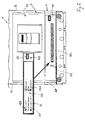
- the present invention relates to a user interface device 41 for a switching device 1 for low voltage electrical circuits.
- the switching device 1 can be constituted, for example, by an automatic circuit breaker, a disconnecting switch, a contactor or other similar devices.
- the switching device 1 comprises one or more electrical poles, each of which comprises one or more pairs of contacts actuable by appropriate control means between at least a first coupling position and a second separation position.
- the switching device 1 comprises a containing enclosure 2 advantageously provided with a front wall 21 and a pair of lateral walls 22.
- the switching device 1 comprises at least one auxiliary device 3 for control and/or setting operation of the switching device 1.
- the auxiliary device is preferably associated inferiorly with the portion of switching device 1 in which the electrical contacts thereof are positioned.
- the auxiliary device 3 is preferably constituted by a protection relay, advantageously operatively connected to one or more sensors and/or actuators 7.
- auxiliary device can indicate any device integrated in the switching device 1 for the purpose of controlling and regulating operation thereof or adding new functions.
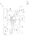
- the auxiliary device 3 comprises a first control unit 310A, advantageously equipped with at least one microprocessor device 310 and one or more memory spaces 311.
- the control unit 310A advantageously interfaces with the sensors and/or actuators 7 of the switching device 1, with which it can exchange control signals and/or data signals.
- the auxiliary device 3 also comprises a power stage 314 suitable to provide electrical power to the control unit 310A to the other circuits of the auxiliary device 3.
- the auxiliary device 3 comprises a first communication port 313, preferably a female USB (Universal Serial Bus) connector.
- a first communication port 313, preferably a female USB (Universal Serial Bus) connector preferably a female USB (Universal Serial Bus) connector.
- the communication port 313 is advantageously connected to the power stage 314 and to the control unit 310A. It can therefore easily exchange data signals, control signals and electrical power with devices external to the auxiliary device 3.
- the interface device 41 is advantageously mechanically associable in a removable manner with the switching device 1, in particular with the front wall 21 thereof.
- the interface device 41 is mounted on the front wall 21A of the auxiliary device 3, on the lower portion of the front wall 21 of the switching device 1.
- the interface device 41 could be mounted on any other area of the walls of the enclosure 2.
- the interface device 41 comprises shaped edges and/or couplings 401 and 402 intended to couple with corresponding grooves 301 e 302, produced on the front wall 21A of the auxiliary device ( Fig. 2 ).
- the interface device 41 is electrically connectable, in a removable manner, to the auxiliary device 3.
- a second communication port 413 advantageously comprising a male USB connector, intended to couple with the female USB connector 313 of the auxiliary device 3.
- the interface device 41 comprises a second control unit 415A, advantageously comprising at least one microprocessor unit 415 and one or more memory spaces 417.
- the control unit 415A is capable of storing data on a local level, i.e. of storing information in the memory spaces 417.
- control unit 415A is capable of exchanging data and/or signals with the control unit 310A.
- the control unit 415A advantageously comprises first processing means 416 suitable to manage the transmission of data and/or signals, for example to the auxiliary device 3 or to other devices connected thereto.
- These data can advantageously comprise one or more predefined configurations relative to the control and regulation functions required for the auxiliary device 3, i.e. sets of control and regulation parameters and variables usable by the auxiliary device 3.
- the control unit 415A is also capable of sending the auxiliary device 3 control signals or other types of data, such as data and/or parameters relative to operation of the switching device 1.
- control unit 415A is capable of receiving data and/or signals from the auxiliary device 3 and/or from other devices connected thereto.
- control unit can advantageously comprise second processing means 416A suitable to manage the reception of data and/or signals, for example input from the control unit 310A.
- the control unit 415A is preferably capable of independently processing, on a local level, data and/or signals.
- control unit 415A can comprise third processing means 416 suitable to locally process data and/or signals, for example in order to process input/output information or store information in the memory spaces 417.
- the processing means 416, 416A and 418 can be produced by means of independent circuit blocks of the control unit 415A or, preferably, as shown in Figs. 5 and 6 , they advantageously comprise one or more programs and/or routines and/or software modules suitable to be executed by the microprocessor unit 415.
- the interface device 41 comprises a display 411 for viewing data or information.
- the display 411 can be of any available type, i.e. monochrome, or active matrix and have any shape, even different from the rectangular shape shown in the aforesaid figures.
- the control unit 415A drives the display 411 by means of an appropriate control driver 411A.
- the display 411 is back-lit, in order to ensure effective viewing of data and information in any environmental condition.
- the switching device 41 preferably comprises means for selecting data and/or signals 412, for example data and/or signals input into and/or output from the second control unit 415A.
- the user By acting on the selection means 412, the user can, for example, select the data to be viewed by means of the display 411 or send control signals to the control unit 415.
- the selection means 412 can comprise one or more hardware buttons operable by the user, such as a sequential selection key, or a pair of selection keys for subsequent levels, or one or more pairs of direction keys, or one or more multifunction keys or joysticks.
- the selection means 412 can be integrated with the display 411, according to the known operating modes of a touch screen display.
- the selection means 412 can comprise one or more icons 412A through which to interact with the control unit 415A.
- the selection means 412 can also be used to select the direction and side for viewing information on the display 411, thereby allowing the user to choose the most suitable viewing direction or side, in relation to the installation configuration of the switching device 1, without varying the position of the display 411 with respect to the enclosure 2.
- the transmission of data from the control unit 415A to the auxiliary device 3 can take place immediately, as soon as the interface device 41 is mounted on the switching device 1 and electrically connected to the auxiliary device 3.
- the transmission of data output from the control unit 415A preferably takes place according to methods selectable by the user by means of appropriate first enabling means.
- the user can use the aforesaid first enabling means to enable the control unit 415A to automatically transmit predefined sets of data (already stored in the memory spaces 417) to the auxiliary device 3.
- the first enabling means can comprise, for example, one or more dedicated enable buttons operable by the user when wishing to enable data transmission.
- the described selection means 412 can be used as first means to enable data transmission.
- the data transferred to the auxiliary device 3 can also be used by the control unit 310 thereof, according to modes and times selectable by the user.
- second enabling means are provided, to enable the auxiliary device 3 to use the data transmitted by the interface device 41.
- the user can use the aforesaid second enabling means to enable the control unit 310 of the auxiliary device 3 to use the data transmitted by the control unit 415A, at any moment, even distant in time from the period in which the aforesaid data are transmitted.
- the second enabling means preferably comprise a microswitch 312 positioned on the front wall 21A of the auxiliary device 3.
- the microswitch 312 is preferably positioned in a manner such as to be covered by the interface device 41 when the latter is mounted on the switching device 1.
- the microswitch 312 can then be operated by the user, once the data has been loaded into the auxiliary device 3 and after removing the interface device 41.
- the described selection means 412 can be used as second enabling means to enable the auxiliary device 3 to use the data transmitted by the interface device 41.
- the user can enable the control unit 310 without removing the interface device 41 from the switching device 1.
- the interface device 41 also comprises acoustic signaling means 420 of the beeper type to improve selection of data and/or controls with acoustic signals for confirmation or to provide alarm signals, for example in the case of programming errors or malfunction.
- the interface device 41 comprises a power stage 419 suitable to manage the power supply of the user interface device 41, in particular of the control unit 415A and of the display 411.
- the power stage 419 is advantageously connected to the USB communication port 413 so as to receive electrical power from the auxiliary device 3.
- the power stage 419 can advantageously comprise a step-up circuit, not shown, suitable to take the input electrical power signal received to higher voltage values, such as voltage values suitable to supply the display 411.
- the power stage 419 can advantageously comprise a buffer battery.
- the interface device 41 comprises a third communication port 414, suitable to electrically connect, in a removable manner, the interface device 41 and/or the auxiliary device 3 to a peripheral device 5.
- the communication port 414 advantageously comprises a female USB connector, advantageously connected to the control unit 415A, to the power stage 419 and to the USB port 413.
- This solution is particularly advantageous given that it provides the user with an input port to the interface device 41 and/or to the auxiliary device 3 which is always available.
- the peripheral device 5 can in fact communicate directly with the auxiliary device 3 and/or with the control unit 415A and be supplied by the auxiliary device 3 by means of the USB ports 313, 413 and 414.
- the peripheral device 5 can be constituted, for example, by a test device comprising a third microprocessor control unit 512 and a power stage 513, to which a fourth communication port 514 is connected, preferably a female USB connector, which can be coupled with the communication port 414 of the interface device 41.
- the device 5 also comprises a display 511 driven by the control unit 512.
- the peripheral device 5 can be realized by a handheld or laptop computer.
- the interface device 41 can be used on any type of switching device, regardless of the presence of other prior art interface devices.
- a further interface device 320 of the DIP switch type, could be associated with the auxiliary device 3, advantageously connected to the control unit 310 of auxiliary device 3.
- the interface device 320 is preferably positioned in a manner such as to be covered by the interface device 41 when this is mounted on the switching device 1.
- the interface device 41 allows the preset aim and the objects to be fully achieved.
- the interface device 41 can be electrically and mechanically connected in a removable manner to the switching device 1.
- the user interface device 41 is advantageously dimensioned in a manner such as to be easily transportable by a user.
- the interface device 41 can also be used as permanent interface of a switching device.
- the interface device 41 is dimensioned in a manner such as to have a very compact structure. In this manner, once mounted in the operating position, it is capable of integrating structurally with a wall of the enclosure 2 of the switching device 1 (in particular with the front wall 21), without significantly increasing the overall dimensions of this switching device.
- the interface device 41 is very flexible and easy to use, making it particularly suitable for use in complex power distribution boards or networks.
- the interface device 41 can be used in any switching device 1, even in the case in which other user interface devices are already present.
- a further advantage derives from the fact that the interface device 41 can allow the connection of tools or peripheral devices to the auxiliary device 3, although it is mounted on the switching device 1.
- the marked structural integrability of the interface device 41 makes it particularly suitable for use also in switching devices of limited size, with limited spaces available on the front wall.
- the interface device 41 greatly facilitates programming of the control and regulation functions of the auxiliary device.
- the user can thus store predefined control and regulation configurations for the auxiliary device 3 in the interface device 41, and transmit these configurations, enabling use thereof according to requirements.
- the interface device 41 can be used as a true mobile unit for programming the auxiliary device 3.
- the interface device 41 also allows constant interaction with the auxiliary device 3 and can be used as a permanent control panel associated with the auxiliary device 3.
- the interface device can also be used as an actual data carrier, for example to download update software, or other data, to the auxiliary device, or to acquire information from the auxiliary device 3 relative to operation of the switching device 1, such as data detected by the sensors 7.
- the interface device 41 could also be used for secondary functions, for example as peripheral device for sending control signals to the auxiliary device 3 or simply for viewing data and information concerning operation of the auxiliary device and/or of the switching device 1. Due to the presence of the display 411, driven by the control unit 415, the interface device 41 allows easy viewing of the input and output data sent/received and can integrate the most up-to-date functions of data viewing and selection.
- the interface device 41 has a relatively simple structure which is suitable to be produced easily and inexpensively at industrial level.
- the user interface device thus conceived is susceptible to numerous modifications and variants, all falling within the inventive concept; moreover all details can be replaced by other technically equivalent details.
- the materials used and the contingent dimensions and forms can be any, according to requirements and to the state of the art.
Landscapes
- Selective Calling Equipment (AREA)
- Remote Monitoring And Control Of Power-Distribution Networks (AREA)
- Cable Transmission Systems, Equalization Of Radio And Reduction Of Echo (AREA)
- Dc Digital Transmission (AREA)
- Electronic Switches (AREA)
Claims (12)
- Dispositif d'interface utilisateur (41) pour un dispositif de commutation (1) de circuits électriques à basse tension, ledit dispositif de commutation comprenant un ou plusieurs pôles électriques, comprenant chacun au moins une paire de contacts actionnables entre une position de couplage et une position de séparation, et un dispositif auxiliaire (3) pour commander et/ou réguler le fonctionnement dudit dispositif de commutation, ledit dispositif auxiliaire comprenant une première unité de commande (310A), caractérisé en ce que ledit dispositif d'interface utilisateur comporte une seconde unité de commande (415A) apte à stocker des données et à échanger des données et/ou des signaux avec ladite première unité de commande, ledit dispositif d'interface utilisateur pouvant être mécaniquement associé, de manière amovible, audit dispositif de commutation, et pouvant être connecté électriquement, de manière amovible, audit dispositif auxiliaire.
- Dispositif d'interface utilisateur selon la revendication 1, caractérisé en ce qu'il comprend au moins un affichage (411) pour visualiser des données et/ou des signaux.
- Dispositif d'interface utilisateur selon l'une ou plusieurs des revendications précédentes, caractérisé en ce que ladite seconde unité de commande comporte un premier moyen de traitement (416) apte à gérer la transmission de données et/ou signaux de sortie.
- Dispositif d'interface utilisateur selon l'une ou plusieurs des revendications précédentes, caractérisé en ce que ladite seconde unité de commande comporte un deuxième moyen de traitement (416A) apte à gérer la réception de données et/ou signaux d'entrée.
- Dispositif d'interface utilisateur selon l'une ou plusieurs des revendications précédentes, caractérisé en ce que ladite seconde unité de commande comporte un troisième moyen de traitement (418) apte à traiter localement des données et/ou des signaux.
- Dispositif d'interface utilisateur selon l'une ou plusieurs des revendications précédentes, caractérisé en ce qu'il comprend un premier moyen d'activation apte à permettre la transmission de données et/ou signaux.
- Dispositif d'interface utilisateur selon l'une ou plusieurs des revendications précédentes, caractérisé en ce qu'il comporte un second moyen d'activation apte à permettre à ladite première unité de commande d'utiliser des données transmises par ladite seconde unité de commande.
- Dispositif d'interface utilisateur selon l'une ou plusieurs des revendications précédentes, caractérisé en ce qu'il comporte au moins un port de communication (414) destiné à se connecter électriquement, de manière amovible, à un dispositif périphérique (5).
- Dispositif d'interface utilisateur selon la revendication 8, caractérisé en ce qu'il connecte électriquement, de façon amovible, ledit dispositif périphérique audit dispositif auxiliaire.
- Dispositif d'interface utilisateur selon l'une ou plusieurs des revendications précédentes, caractérisé en ce que ledit dispositif auxiliaire (3) est un relais de protection.
- Dispositif de commutation (1), caractérisé en ce qu'il comprend un dispositif d'interface utilisateur (41) selon l'une ou plusieurs des revendications précédentes.
- Dispositif de commutation (1) pour des circuits électriques à basse tension comprenant un ou plusieurs pôles électriques, lesquels comportent chacun au moins une paire de contacts actionnables entre une position de couplage et une position de séparation, et un dispositif auxiliaire (3) pour commander et/ou réguler le fonctionnement dudit dispositif de commutation, ledit dispositif auxiliaire comprenant une première unité de commande (310A), caractérisé en ce qu'un dispositif d'interface utilisateur (41), comportant une seconde unité de commande (415A) apte à stocker des données et à échanger des données et/ou des signaux avec ladite première unité de commande, est susceptible d'être mécaniquement associé, de manière amovible, audit dispositif de commutation, et peut être connecté électriquement, de manière amovible, audit dispositif auxiliaire.
Applications Claiming Priority (2)
| Application Number | Priority Date | Filing Date | Title |
|---|---|---|---|
| ITMI2008A001579A IT1391565B1 (it) | 2008-09-03 | 2008-09-03 | Un dispositivo d'interfaccia utente per dispositivi di commutazione in bassa tensione |
| PCT/EP2009/060058 WO2010026013A1 (fr) | 2008-09-03 | 2009-08-03 | Dispositif d'interface utilisateur pour des dispositifs de communication à basse tension |
Publications (2)
| Publication Number | Publication Date |
|---|---|
| EP2321836A1 EP2321836A1 (fr) | 2011-05-18 |
| EP2321836B1 true EP2321836B1 (fr) | 2016-03-02 |
Family
ID=40527537
Family Applications (1)
| Application Number | Title | Priority Date | Filing Date |
|---|---|---|---|
| EP09811095.0A Revoked EP2321836B1 (fr) | 2008-09-03 | 2009-08-03 | Dispositif d'interface utilisateur pour des dispositifs de commutation à basse tension |
Country Status (6)
| Country | Link |
|---|---|
| US (1) | US8928186B2 (fr) |
| EP (1) | EP2321836B1 (fr) |
| CN (1) | CN102144273B (fr) |
| ES (1) | ES2572617T3 (fr) |
| IT (1) | IT1391565B1 (fr) |
| WO (1) | WO2010026013A1 (fr) |
Families Citing this family (17)
| Publication number | Priority date | Publication date | Assignee | Title |
|---|---|---|---|---|
| USD245721S (en) * | 1976-03-15 | 1977-09-06 | Koch Bernard C | Golf club head |
| USD587658S1 (en) * | 2005-05-10 | 2009-03-03 | Abb S.P.A. | Circuit breaker |
| EP2383850B1 (fr) | 2010-04-30 | 2017-08-09 | ABB Schweiz AG | Procédé de réalisation d'un entretien/d'une maintenance sur un tableau de commutation et tableau de commutation correspondant |
| CN103370762B (zh) | 2010-10-01 | 2017-04-05 | Abb 技术有限公司 | 自供电继电器中的dip开关变化检测 |
| SG180051A1 (en) * | 2010-10-28 | 2012-05-30 | Rockwell Automation Asia Pacific Business Ctr Pte Ltd | Display module for toolless coupling with programmable controller |
| DE102011006112B4 (de) * | 2011-03-25 | 2024-01-18 | Siemens Aktiengesellschaft | Elektrischer Schalter und Überstromauslösemodul |
| DE102011083825A1 (de) * | 2011-09-30 | 2013-04-04 | Siemens Aktiengesellschaft | Schalter, insbesondere Leistungsschalter für Niederspannungen |
| ES2537528T3 (es) * | 2012-07-24 | 2015-06-09 | Abb S.P.A. | Interruptor de estado sólido mejorado |
| US20140118875A1 (en) * | 2012-10-31 | 2014-05-01 | Eaton Corporation | Control and monitoring unit for a circuit interrupter electronic trip unit and system including same |
| BR302013002177S1 (pt) | 2012-11-09 | 2014-11-25 | Abb Spa | Configuração aplicada em fusível. |
| US10243345B2 (en) | 2015-06-30 | 2019-03-26 | AB Schweiz AG | Circuit breaker having breaker information module and method of use |
| CN105182821B (zh) * | 2015-08-27 | 2018-10-26 | 吴剑辉 | 一种抓握触控式遥控器 |
| USD884658S1 (en) * | 2018-04-18 | 2020-05-19 | Abb S.P.A. | Circuit breaker |
| RU183388U1 (ru) * | 2018-05-22 | 2018-09-20 | Акционерное общество "Промышленная группа "Метран" | Система защиты от высоких напряжений и токов выполненного на твердотельном реле коммутационного устройства |
| USD971857S1 (en) * | 2020-05-19 | 2022-12-06 | National Breaker Services LLC | Display panel for electric circuit breaker |
| DE102020210973A1 (de) | 2020-08-31 | 2022-03-03 | Siemens Aktiengesellschaft | Leistungsschalter und Display |
| US11500367B2 (en) * | 2020-09-23 | 2022-11-15 | Rockwell Automation Technologies, Inc. | Display for self-powered industrial automation component |
Citations (5)
| Publication number | Priority date | Publication date | Assignee | Title |
|---|---|---|---|---|
| US4870531A (en) | 1988-08-15 | 1989-09-26 | General Electric Company | Circuit breaker with removable display and keypad |
| US5426592A (en) | 1992-03-06 | 1995-06-20 | Siemens Energy & Automation, Inc. | Circuit breaker trip unit which automatically adapts to operated with a particular display module |
| US6169651B1 (en) | 1998-06-05 | 2001-01-02 | General Electric Company | Protective relay with modular control panel |
| US7167348B2 (en) | 2001-12-21 | 2007-01-23 | Amt Capital, Ltd. | Miniaturized motor overload protector |
| EP2068336A1 (fr) | 2007-12-05 | 2009-06-10 | ABB Technology AG | Relais de protection et son interface homme-machine |
Family Cites Families (5)
| Publication number | Priority date | Publication date | Assignee | Title |
|---|---|---|---|---|
| US6292717B1 (en) * | 1998-03-19 | 2001-09-18 | Siemens Energy & Automation, Inc. | Energy information device and graphical display for a circuit breaker |
| DE19812423A1 (de) * | 1998-03-20 | 1999-09-23 | Moeller Gmbh | Bedientasten als aktive Tasten |
| FR2798524B1 (fr) * | 1999-09-13 | 2001-11-02 | Schneider Electric Ind Sa | Declencheur comportant une interface homme-machine amelioree et disjoncteur comportant un tel dispositif |
| JP2008077233A (ja) * | 2006-09-19 | 2008-04-03 | Toshiba Corp | 情報処理装置 |
| US7925798B2 (en) * | 2007-01-26 | 2011-04-12 | Lantiq Deutschland Gmbh | Data packet processing device |
-
2008
- 2008-09-03 IT ITMI2008A001579A patent/IT1391565B1/it active
-
2009
- 2009-08-03 US US13/061,633 patent/US8928186B2/en active Active
- 2009-08-03 CN CN200980134072.2A patent/CN102144273B/zh active Active
- 2009-08-03 ES ES09811095.0T patent/ES2572617T3/es active Active
- 2009-08-03 EP EP09811095.0A patent/EP2321836B1/fr not_active Revoked
- 2009-08-03 WO PCT/EP2009/060058 patent/WO2010026013A1/fr active Application Filing
Patent Citations (5)
| Publication number | Priority date | Publication date | Assignee | Title |
|---|---|---|---|---|
| US4870531A (en) | 1988-08-15 | 1989-09-26 | General Electric Company | Circuit breaker with removable display and keypad |
| US5426592A (en) | 1992-03-06 | 1995-06-20 | Siemens Energy & Automation, Inc. | Circuit breaker trip unit which automatically adapts to operated with a particular display module |
| US6169651B1 (en) | 1998-06-05 | 2001-01-02 | General Electric Company | Protective relay with modular control panel |
| US7167348B2 (en) | 2001-12-21 | 2007-01-23 | Amt Capital, Ltd. | Miniaturized motor overload protector |
| EP2068336A1 (fr) | 2007-12-05 | 2009-06-10 | ABB Technology AG | Relais de protection et son interface homme-machine |
Non-Patent Citations (1)
| Title |
|---|
| "OKI Semiconductor MSM5265GS", OKI, November 1997 (1997-11-01), pages 1 - 18, XP055328333 |
Also Published As
| Publication number | Publication date |
|---|---|
| IT1391565B1 (it) | 2012-01-11 |
| CN102144273B (zh) | 2016-03-02 |
| ITMI20081579A1 (it) | 2010-03-04 |
| US8928186B2 (en) | 2015-01-06 |
| EP2321836A1 (fr) | 2011-05-18 |
| CN102144273A (zh) | 2011-08-03 |
| WO2010026013A1 (fr) | 2010-03-11 |
| ES2572617T3 (es) | 2016-06-01 |
| US20110186408A1 (en) | 2011-08-04 |
Similar Documents
| Publication | Publication Date | Title |
|---|---|---|
| EP2321836B1 (fr) | Dispositif d'interface utilisateur pour des dispositifs de commutation à basse tension | |
| US11289859B2 (en) | Electrical communication switch, outlet, companion device, and system | |
| WO2012141839A4 (fr) | Procédé et appareil pour combiner un relais de puissance ca et des capteurs de courant avec des dispositifs de câblage ca | |
| CN109616378B (zh) | 一种急停控制装置、机器人及其急停控制方法 | |
| JP2011515797A (ja) | コンセント | |
| CN107419765B (zh) | 多功能设备切换控制设备、控制系统及属具 | |
| CN101322209B (zh) | 监测连接在开关设备上游的保护装置的方法和系统 | |
| CN101025616A (zh) | 具有多设备控制器的无线系统 | |
| US8255064B2 (en) | Remote CNC machine control switch | |
| WO2011162517A2 (fr) | Système d'arrêt de l'alimentation de veille | |
| CN102456991A (zh) | 可遥控启闭电源的电源插座装置及其遥控式电源插座 | |
| CN215344091U (zh) | 可远程控制开关启停配电箱 | |
| US8063733B2 (en) | Device for communicating with a system | |
| CN210724309U (zh) | 自动转换开关控制装置 | |
| JP2012055124A (ja) | ワイヤレス電源供給制御システムおよびこのシステムに用いる電源コンセント | |
| JPH0793053A (ja) | Posシステム用制御ボード | |
| EP2728605B1 (fr) | Dispositif de commutation électrique de circuits basse tension | |
| CN213694591U (zh) | 一种自动化工控行业的plc控制柜 | |
| CN219321285U (zh) | 电子脱扣器的智能控制装置及电子脱扣器 | |
| JP6987680B2 (ja) | スマートメータ通信装置 | |
| CN217034531U (zh) | 一种安全控制电路及控制设备 | |
| KR200269527Y1 (ko) | 원격전원제어장치 | |
| KR101439214B1 (ko) | 모듈 타입 휴대용 로봇컨트롤러 | |
| KR101462871B1 (ko) | 사용전력량 확인 기능을 포함하는 유에스비가 구비된 멀티탭 | |
| KR200363756Y1 (ko) | 계전기 원격 제어장치 |
Legal Events
| Date | Code | Title | Description |
|---|---|---|---|
| PUAI | Public reference made under article 153(3) epc to a published international application that has entered the european phase |
Free format text: ORIGINAL CODE: 0009012 |
|
| 17P | Request for examination filed |
Effective date: 20110127 |
|
| AK | Designated contracting states |
Kind code of ref document: A1 Designated state(s): AT BE BG CH CY CZ DE DK EE ES FI FR GB GR HR HU IE IS IT LI LT LU LV MC MK MT NL NO PL PT RO SE SI SK SM TR |
|
| AX | Request for extension of the european patent |
Extension state: AL BA RS |
|
| DAX | Request for extension of the european patent (deleted) | ||
| GRAP | Despatch of communication of intention to grant a patent |
Free format text: ORIGINAL CODE: EPIDOSNIGR1 |
|
| INTG | Intention to grant announced |
Effective date: 20150907 |
|
| GRAS | Grant fee paid |
Free format text: ORIGINAL CODE: EPIDOSNIGR3 |
|
| GRAA | (expected) grant |
Free format text: ORIGINAL CODE: 0009210 |
|
| STAA | Information on the status of an ep patent application or granted ep patent |
Free format text: STATUS: THE PATENT HAS BEEN GRANTED |
|
| AK | Designated contracting states |
Kind code of ref document: B1 Designated state(s): AT BE BG CH CY CZ DE DK EE ES FI FR GB GR HR HU IE IS IT LI LT LU LV MC MK MT NL NO PL PT RO SE SI SK SM TR |
|
| REG | Reference to a national code |
Ref country code: GB Ref legal event code: FG4D |
|
| REG | Reference to a national code |
Ref country code: AT Ref legal event code: REF Ref document number: 778528 Country of ref document: AT Kind code of ref document: T Effective date: 20160315 Ref country code: CH Ref legal event code: EP |
|
| REG | Reference to a national code |
Ref country code: IE Ref legal event code: FG4D |
|
| REG | Reference to a national code |
Ref country code: DE Ref legal event code: R096 Ref document number: 602009036607 Country of ref document: DE |
|
| REG | Reference to a national code |
Ref country code: ES Ref legal event code: FG2A Ref document number: 2572617 Country of ref document: ES Kind code of ref document: T3 Effective date: 20160601 |
|
| REG | Reference to a national code |
Ref country code: SE Ref legal event code: TRGR |
|
| REG | Reference to a national code |
Ref country code: NL Ref legal event code: MP Effective date: 20160302 |
|
| REG | Reference to a national code |
Ref country code: LT Ref legal event code: MG4D |
|
| REG | Reference to a national code |
Ref country code: AT Ref legal event code: MK05 Ref document number: 778528 Country of ref document: AT Kind code of ref document: T Effective date: 20160302 |
|
| PG25 | Lapsed in a contracting state [announced via postgrant information from national office to epo] |
Ref country code: HR Free format text: LAPSE BECAUSE OF FAILURE TO SUBMIT A TRANSLATION OF THE DESCRIPTION OR TO PAY THE FEE WITHIN THE PRESCRIBED TIME-LIMIT Effective date: 20160302 Ref country code: GR Free format text: LAPSE BECAUSE OF FAILURE TO SUBMIT A TRANSLATION OF THE DESCRIPTION OR TO PAY THE FEE WITHIN THE PRESCRIBED TIME-LIMIT Effective date: 20160603 Ref country code: FI Free format text: LAPSE BECAUSE OF FAILURE TO SUBMIT A TRANSLATION OF THE DESCRIPTION OR TO PAY THE FEE WITHIN THE PRESCRIBED TIME-LIMIT Effective date: 20160302 Ref country code: NO Free format text: LAPSE BECAUSE OF FAILURE TO SUBMIT A TRANSLATION OF THE DESCRIPTION OR TO PAY THE FEE WITHIN THE PRESCRIBED TIME-LIMIT Effective date: 20160602 |
|
| REG | Reference to a national code |
Ref country code: FR Ref legal event code: PLFP Year of fee payment: 8 |
|
| PG25 | Lapsed in a contracting state [announced via postgrant information from national office to epo] |
Ref country code: NL Free format text: LAPSE BECAUSE OF FAILURE TO SUBMIT A TRANSLATION OF THE DESCRIPTION OR TO PAY THE FEE WITHIN THE PRESCRIBED TIME-LIMIT Effective date: 20160302 Ref country code: PL Free format text: LAPSE BECAUSE OF FAILURE TO SUBMIT A TRANSLATION OF THE DESCRIPTION OR TO PAY THE FEE WITHIN THE PRESCRIBED TIME-LIMIT Effective date: 20160302 Ref country code: AT Free format text: LAPSE BECAUSE OF FAILURE TO SUBMIT A TRANSLATION OF THE DESCRIPTION OR TO PAY THE FEE WITHIN THE PRESCRIBED TIME-LIMIT Effective date: 20160302 Ref country code: LT Free format text: LAPSE BECAUSE OF FAILURE TO SUBMIT A TRANSLATION OF THE DESCRIPTION OR TO PAY THE FEE WITHIN THE PRESCRIBED TIME-LIMIT Effective date: 20160302 Ref country code: LV Free format text: LAPSE BECAUSE OF FAILURE TO SUBMIT A TRANSLATION OF THE DESCRIPTION OR TO PAY THE FEE WITHIN THE PRESCRIBED TIME-LIMIT Effective date: 20160302 |
|
| PG25 | Lapsed in a contracting state [announced via postgrant information from national office to epo] |
Ref country code: EE Free format text: LAPSE BECAUSE OF FAILURE TO SUBMIT A TRANSLATION OF THE DESCRIPTION OR TO PAY THE FEE WITHIN THE PRESCRIBED TIME-LIMIT Effective date: 20160302 Ref country code: IS Free format text: LAPSE BECAUSE OF FAILURE TO SUBMIT A TRANSLATION OF THE DESCRIPTION OR TO PAY THE FEE WITHIN THE PRESCRIBED TIME-LIMIT Effective date: 20160702 |
|
| REG | Reference to a national code |
Ref country code: DE Ref legal event code: R026 Ref document number: 602009036607 Country of ref document: DE |
|
| PG25 | Lapsed in a contracting state [announced via postgrant information from national office to epo] |
Ref country code: CZ Free format text: LAPSE BECAUSE OF FAILURE TO SUBMIT A TRANSLATION OF THE DESCRIPTION OR TO PAY THE FEE WITHIN THE PRESCRIBED TIME-LIMIT Effective date: 20160302 Ref country code: SM Free format text: LAPSE BECAUSE OF FAILURE TO SUBMIT A TRANSLATION OF THE DESCRIPTION OR TO PAY THE FEE WITHIN THE PRESCRIBED TIME-LIMIT Effective date: 20160302 Ref country code: SK Free format text: LAPSE BECAUSE OF FAILURE TO SUBMIT A TRANSLATION OF THE DESCRIPTION OR TO PAY THE FEE WITHIN THE PRESCRIBED TIME-LIMIT Effective date: 20160302 Ref country code: RO Free format text: LAPSE BECAUSE OF FAILURE TO SUBMIT A TRANSLATION OF THE DESCRIPTION OR TO PAY THE FEE WITHIN THE PRESCRIBED TIME-LIMIT Effective date: 20160302 Ref country code: PT Free format text: LAPSE BECAUSE OF FAILURE TO SUBMIT A TRANSLATION OF THE DESCRIPTION OR TO PAY THE FEE WITHIN THE PRESCRIBED TIME-LIMIT Effective date: 20160704 |
|
| PLBI | Opposition filed |
Free format text: ORIGINAL CODE: 0009260 |
|
| PG25 | Lapsed in a contracting state [announced via postgrant information from national office to epo] |
Ref country code: BE Free format text: LAPSE BECAUSE OF FAILURE TO SUBMIT A TRANSLATION OF THE DESCRIPTION OR TO PAY THE FEE WITHIN THE PRESCRIBED TIME-LIMIT Effective date: 20160302 |
|
| 26 | Opposition filed |
Opponent name: SIEMENS AKTIENGESELLSCHAFT Effective date: 20161124 |
|
| PLAX | Notice of opposition and request to file observation + time limit sent |
Free format text: ORIGINAL CODE: EPIDOSNOBS2 |
|
| PG25 | Lapsed in a contracting state [announced via postgrant information from national office to epo] |
Ref country code: DK Free format text: LAPSE BECAUSE OF FAILURE TO SUBMIT A TRANSLATION OF THE DESCRIPTION OR TO PAY THE FEE WITHIN THE PRESCRIBED TIME-LIMIT Effective date: 20160302 |
|
| PG25 | Lapsed in a contracting state [announced via postgrant information from national office to epo] |
Ref country code: BG Free format text: LAPSE BECAUSE OF FAILURE TO SUBMIT A TRANSLATION OF THE DESCRIPTION OR TO PAY THE FEE WITHIN THE PRESCRIBED TIME-LIMIT Effective date: 20160602 Ref country code: SI Free format text: LAPSE BECAUSE OF FAILURE TO SUBMIT A TRANSLATION OF THE DESCRIPTION OR TO PAY THE FEE WITHIN THE PRESCRIBED TIME-LIMIT Effective date: 20160302 |
|
| PG25 | Lapsed in a contracting state [announced via postgrant information from national office to epo] |
Ref country code: MC Free format text: LAPSE BECAUSE OF FAILURE TO SUBMIT A TRANSLATION OF THE DESCRIPTION OR TO PAY THE FEE WITHIN THE PRESCRIBED TIME-LIMIT Effective date: 20160302 |
|
| REG | Reference to a national code |
Ref country code: CH Ref legal event code: PL |
|
| PG25 | Lapsed in a contracting state [announced via postgrant information from national office to epo] |
Ref country code: LI Free format text: LAPSE BECAUSE OF NON-PAYMENT OF DUE FEES Effective date: 20160831 Ref country code: CH Free format text: LAPSE BECAUSE OF NON-PAYMENT OF DUE FEES Effective date: 20160831 |
|
| PLBB | Reply of patent proprietor to notice(s) of opposition received |
Free format text: ORIGINAL CODE: EPIDOSNOBS3 |
|
| REG | Reference to a national code |
Ref country code: IE Ref legal event code: MM4A |
|
| PG25 | Lapsed in a contracting state [announced via postgrant information from national office to epo] |
Ref country code: IE Free format text: LAPSE BECAUSE OF NON-PAYMENT OF DUE FEES Effective date: 20160803 |
|
| REG | Reference to a national code |
Ref country code: FR Ref legal event code: PLFP Year of fee payment: 9 |
|
| PG25 | Lapsed in a contracting state [announced via postgrant information from national office to epo] |
Ref country code: LU Free format text: LAPSE BECAUSE OF NON-PAYMENT OF DUE FEES Effective date: 20160803 |
|
| PLAB | Opposition data, opponent's data or that of the opponent's representative modified |
Free format text: ORIGINAL CODE: 0009299OPPO |
|
| R26 | Opposition filed (corrected) |
Opponent name: SIEMENS AKTIENGESELLSCHAFT Effective date: 20161124 |
|
| PG25 | Lapsed in a contracting state [announced via postgrant information from national office to epo] |
Ref country code: CY Free format text: LAPSE BECAUSE OF FAILURE TO SUBMIT A TRANSLATION OF THE DESCRIPTION OR TO PAY THE FEE WITHIN THE PRESCRIBED TIME-LIMIT Effective date: 20160302 Ref country code: HU Free format text: LAPSE BECAUSE OF FAILURE TO SUBMIT A TRANSLATION OF THE DESCRIPTION OR TO PAY THE FEE WITHIN THE PRESCRIBED TIME-LIMIT; INVALID AB INITIO Effective date: 20090803 |
|
| PG25 | Lapsed in a contracting state [announced via postgrant information from national office to epo] |
Ref country code: MK Free format text: LAPSE BECAUSE OF FAILURE TO SUBMIT A TRANSLATION OF THE DESCRIPTION OR TO PAY THE FEE WITHIN THE PRESCRIBED TIME-LIMIT Effective date: 20160302 Ref country code: MT Free format text: LAPSE BECAUSE OF NON-PAYMENT OF DUE FEES Effective date: 20160831 Ref country code: TR Free format text: LAPSE BECAUSE OF FAILURE TO SUBMIT A TRANSLATION OF THE DESCRIPTION OR TO PAY THE FEE WITHIN THE PRESCRIBED TIME-LIMIT Effective date: 20160302 |
|
| REG | Reference to a national code |
Ref country code: FR Ref legal event code: PLFP Year of fee payment: 10 |
|
| RDAF | Communication despatched that patent is revoked |
Free format text: ORIGINAL CODE: EPIDOSNREV1 |
|
| STAA | Information on the status of an ep patent application or granted ep patent |
Free format text: STATUS: THE PATENT HAS BEEN GRANTED |
|
| APBM | Appeal reference recorded |
Free format text: ORIGINAL CODE: EPIDOSNREFNO |
|
| APBP | Date of receipt of notice of appeal recorded |
Free format text: ORIGINAL CODE: EPIDOSNNOA2O |
|
| APAH | Appeal reference modified |
Free format text: ORIGINAL CODE: EPIDOSCREFNO |
|
| APBQ | Date of receipt of statement of grounds of appeal recorded |
Free format text: ORIGINAL CODE: EPIDOSNNOA3O |
|
| PGFP | Annual fee paid to national office [announced via postgrant information from national office to epo] |
Ref country code: IT Payment date: 20210830 Year of fee payment: 13 Ref country code: FR Payment date: 20210819 Year of fee payment: 13 |
|
| PGFP | Annual fee paid to national office [announced via postgrant information from national office to epo] |
Ref country code: GB Payment date: 20210820 Year of fee payment: 13 Ref country code: SE Payment date: 20210819 Year of fee payment: 13 Ref country code: DE Payment date: 20210819 Year of fee payment: 13 |
|
| REG | Reference to a national code |
Ref country code: DE Ref legal event code: R103 Ref document number: 602009036607 Country of ref document: DE Ref country code: DE Ref legal event code: R064 Ref document number: 602009036607 Country of ref document: DE |
|
| APBU | Appeal procedure closed |
Free format text: ORIGINAL CODE: EPIDOSNNOA9O |
|
| RDAG | Patent revoked |
Free format text: ORIGINAL CODE: 0009271 |
|
| STAA | Information on the status of an ep patent application or granted ep patent |
Free format text: STATUS: PATENT REVOKED |
|
| PGFP | Annual fee paid to national office [announced via postgrant information from national office to epo] |
Ref country code: ES Payment date: 20211025 Year of fee payment: 13 |
|
| REG | Reference to a national code |
Ref country code: FI Ref legal event code: MGE |
|
| 27W | Patent revoked |
Effective date: 20211222 |
|
| GBPR | Gb: patent revoked under art. 102 of the ep convention designating the uk as contracting state |
Effective date: 20211222 |
|
| REG | Reference to a national code |
Ref country code: SE Ref legal event code: ECNC |
|
| PLAB | Opposition data, opponent's data or that of the opponent's representative modified |
Free format text: ORIGINAL CODE: 0009299OPPO |
|
| R26 | Opposition filed (corrected) |
Opponent name: SIEMENS AKTIENGESELLSCHAFT Effective date: 20161124 |