EP2321540B1 - Kraftfahrzeugmotorlüftersystem stützenden düse und vorrichtung zur befestigung eines energieversorgungsrelaisgehäuses des motorlüftersystems an der düse. - Google Patents
Kraftfahrzeugmotorlüftersystem stützenden düse und vorrichtung zur befestigung eines energieversorgungsrelaisgehäuses des motorlüftersystems an der düse. Download PDFInfo
- Publication number
- EP2321540B1 EP2321540B1 EP09741377.7A EP09741377A EP2321540B1 EP 2321540 B1 EP2321540 B1 EP 2321540B1 EP 09741377 A EP09741377 A EP 09741377A EP 2321540 B1 EP2321540 B1 EP 2321540B1
- Authority
- EP
- European Patent Office
- Prior art keywords
- fixing
- positioning
- fan system
- relative
- motor
- Prior art date
- Legal status (The legal status is an assumption and is not a legal conclusion. Google has not performed a legal analysis and makes no representation as to the accuracy of the status listed.)
- Active
Links
- 230000001154 acute effect Effects 0.000 claims description 3
- 230000000295 complement effect Effects 0.000 claims description 2
- WSNMPAVSZJSIMT-UHFFFAOYSA-N COc1c(C)c2COC(=O)c2c(O)c1CC(O)C1(C)CCC(=O)O1 Chemical compound COc1c(C)c2COC(=O)c2c(O)c1CC(O)C1(C)CCC(=O)O1 WSNMPAVSZJSIMT-UHFFFAOYSA-N 0.000 description 1
- 238000005452 bending Methods 0.000 description 1
- 230000000694 effects Effects 0.000 description 1
- 239000002184 metal Substances 0.000 description 1
- 238000000034 method Methods 0.000 description 1
- 210000000056 organ Anatomy 0.000 description 1
Images


Classifications
-
- F—MECHANICAL ENGINEERING; LIGHTING; HEATING; WEAPONS; BLASTING
- F16—ENGINEERING ELEMENTS AND UNITS; GENERAL MEASURES FOR PRODUCING AND MAINTAINING EFFECTIVE FUNCTIONING OF MACHINES OR INSTALLATIONS; THERMAL INSULATION IN GENERAL
- F16B—DEVICES FOR FASTENING OR SECURING CONSTRUCTIONAL ELEMENTS OR MACHINE PARTS TOGETHER, e.g. NAILS, BOLTS, CIRCLIPS, CLAMPS, CLIPS OR WEDGES; JOINTS OR JOINTING
- F16B5/00—Joining sheets or plates, e.g. panels, to one another or to strips or bars parallel to them
- F16B5/06—Joining sheets or plates, e.g. panels, to one another or to strips or bars parallel to them by means of clamps or clips
- F16B5/0607—Joining sheets or plates, e.g. panels, to one another or to strips or bars parallel to them by means of clamps or clips joining sheets or plates to each other
- F16B5/0621—Joining sheets or plates, e.g. panels, to one another or to strips or bars parallel to them by means of clamps or clips joining sheets or plates to each other in parallel relationship
- F16B5/0635—Joining sheets or plates, e.g. panels, to one another or to strips or bars parallel to them by means of clamps or clips joining sheets or plates to each other in parallel relationship fastened over the edges of the sheets or plates
-
- F—MECHANICAL ENGINEERING; LIGHTING; HEATING; WEAPONS; BLASTING
- F16—ENGINEERING ELEMENTS AND UNITS; GENERAL MEASURES FOR PRODUCING AND MAINTAINING EFFECTIVE FUNCTIONING OF MACHINES OR INSTALLATIONS; THERMAL INSULATION IN GENERAL
- F16B—DEVICES FOR FASTENING OR SECURING CONSTRUCTIONAL ELEMENTS OR MACHINE PARTS TOGETHER, e.g. NAILS, BOLTS, CIRCLIPS, CLAMPS, CLIPS OR WEDGES; JOINTS OR JOINTING
- F16B2/00—Friction-grip releasable fastenings
- F16B2/20—Clips, i.e. with gripping action effected solely by the inherent resistance to deformation of the material of the fastening
- F16B2/22—Clips, i.e. with gripping action effected solely by the inherent resistance to deformation of the material of the fastening of resilient material, e.g. rubbery material
- F16B2/24—Clips, i.e. with gripping action effected solely by the inherent resistance to deformation of the material of the fastening of resilient material, e.g. rubbery material of metal
- F16B2/241—Clips, i.e. with gripping action effected solely by the inherent resistance to deformation of the material of the fastening of resilient material, e.g. rubbery material of metal of sheet metal
- F16B2/245—Clips, i.e. with gripping action effected solely by the inherent resistance to deformation of the material of the fastening of resilient material, e.g. rubbery material of metal of sheet metal external, i.e. with contracting action
-
- F—MECHANICAL ENGINEERING; LIGHTING; HEATING; WEAPONS; BLASTING
- F16—ENGINEERING ELEMENTS AND UNITS; GENERAL MEASURES FOR PRODUCING AND MAINTAINING EFFECTIVE FUNCTIONING OF MACHINES OR INSTALLATIONS; THERMAL INSULATION IN GENERAL
- F16B—DEVICES FOR FASTENING OR SECURING CONSTRUCTIONAL ELEMENTS OR MACHINE PARTS TOGETHER, e.g. NAILS, BOLTS, CIRCLIPS, CLAMPS, CLIPS OR WEDGES; JOINTS OR JOINTING
- F16B21/00—Means for preventing relative axial movement of a pin, spigot, shaft or the like and a member surrounding it; Stud-and-socket releasable fastenings
- F16B21/06—Releasable fastening devices with snap-action
- F16B21/07—Releasable fastening devices with snap-action in which the socket has a resilient part
- F16B21/071—Releasable fastening devices with snap-action in which the socket has a resilient part the socket being integrally formed with a component to be fasted, e.g. a sheet, plate or strip
Definitions
- the present invention relates to a device for fixing an element, in particular a power supply relay box of a motorcycle fan unit, on a structure, in particular a nozzle supporting a motorcycle fan unit in an engine compartment of a motor vehicle.
- the invention also relates to a method of assembling such an element on such a structure.
- the invention further relates to a structure adapted to receive the fixing device.
- the object of the invention is therefore to provide a fixing device for mounting an element on a motor vehicle.
- the invention proposes a simple, inexpensive fastening device that allows assembly to be carried out easily, quickly and effortlessly.
- the device according to the invention makes it possible to fix an element on a structure II is characterized in that it comprises at least a first fixing means intended to act by pinching on a first rib of the structure and a second fixing means intended to act by pinching on a second rib of the structure, the device comprising a positioning means positioning and / or orienting relative to each other the first and second fixing means.
- the positioning means of the first and second means relative to each other may be such that the first and second means form an acute angle greater than 30 ° and, preferably, greater than 45 °.
- the positioning means of the first and second means relative to each other may be such that the first and second means form at least substantially a right angle.
- the positioning means may be part of the element.
- the first and second fastening means may be staples.
- the element can be a power relay box of a motorcycle fan motor vehicle.
- a structure comprises ribs adapted to cooperate with a fixing device defined above.
- the ribs may include keying protuberances.
- the structure may consist of a nozzle intended to support a motorcycle fan unit of a motor vehicle.
- a motor vehicle comprises a device defined above.
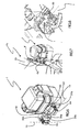
- the figure 1 is a front view from inside the engine compartment of a front face of a motor vehicle, this face mainly comprising a motorcycle fan unit and a structure supporting this motorcycle fan unit.
- the figure 2 is a front view of a clip for fixing an element to a structure according to one embodiment of the fixing device according to the invention.
- the figure 3 is a side view of this clip.
- the figure 4 is a top view of this clip.
- the figure 5 is a perspective view of this clip.
- FIGS. 6 and 9 are perspective views of an element intended to be fixed on a structure by means of a fixing device according to the invention.
- FIGS. 7 and 8 are perspective views of an element fixed to a structure by means of a fastening device according to the invention.
- the figure 10 is a sectional view, at a first fastening means, of an element attached to a structure.
- the figure 11 is a sectional view, at a second fastening means, of an element attached to a structure.
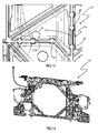
- the Figures 12 and 13 are views of a structure adapted to receive a fixing device according to the invention.
- FIG. figure 1 A portion of the front face 3 of a motor vehicle is shown in FIG. figure 1 .
- a nozzle-shaped structure 15 having an opening 23 in which is fixed, on the structure, a motorcycle fan unit 16. It also distinguishes an electrical harness 5 composed of different sleeves 4 and a relay housing 1 of motorcycle fan unit power supply. This housing has the particularity of being fixed to the structure.
- the fixing of the housing 1 on the structure 15 is provided by a fixing device 20 comprising a first fixing means 6a and a second fixing means 6b.
- a positioning means 24 makes it possible to position and / or orient the first and second fixing means with respect to one another.
- the term "set in position and / or orient relative to each other the first and second fastening means” block degrees of freedom of the first and second fastening means.
- all the degrees of freedom of the first fixing means are locked relative to the second fastening means and relative to the positioning means, the positioning means supporting the first and second fastening means.
- the first and second fixing means are integral with the positioning means, that is to say rigidly fixed to the positioning means.
- the positioning means is rigid, that is to say that under the effect of mechanical actions, it will very little deform unlike a passing sheath of a bundle of electric wire for example which will deform a lot, especially under bending stresses.
- the first and second fixing means act by pinching, that is to say that they comprise elements pinching pinch zones, for example ribs 7a, 7b, of the structure to which they must be fixed. . Fixing is then ensured by phenomena of friction and / or arching at the level of the pinching organ interfaces-pinch zones.
- the fixing means may consist of clips 6, 6a, 6b as shown in FIGS. Figures 2 to 5 .
- These clips are generally in the form of a U-profile with two wings 8 extending parallel and whose recess 9, formed between these wings, is intended to receive a nip 21a, 21b of the structure.
- a first set of elastic strips 10 extending opposite each other from the flanges and a second set of elastic strips 11 extending opposite each other from the flanges are provided in the recess of the U.
- These are the lamellae which come into contact and which exert, by their deformation, mechanical actions on the pinching zone of the structure. These mechanical actions then give rise to friction forces or even arches, opposing the withdrawal of the pinching zone of the hollow 9.
- the blades forming an angle with the wings the pinching zone can penetrate in the hollow easily.
- These staples are for example of the metallo-plastic type, with a U-shaped plastic profile and metal strips reported.
- the two wings are connected to each other by a base 30.
- This base has for example means for fixing the clip to the positioning means 24.
- These means comprise for example a first slide element, such as a pad 31 , 31 a, 31 b, intended to cooperate with a second slide member, such as a rail 32a, 32b of complementary shape to that of the pad, the second slide member being provided on the positioning means.
- These means still include a locking means such as a lug 33 provided at the end of an elastic tongue 34, 34a, 34b and intended to cooperate with a hole in the second slide member to prevent the movement of the two slide elements relative to the other and therefore their disassembly.
- the fixing means may be fixed, by any other removable connection or not, to the positioning means.
- they can be crimped or welded.
- the connection blocks all the degrees of freedom of the fixing means. This is not necessarily necessary.
- the degree of freedom of rotation of the fastening means along an axis perpendicular to their base can be preserved. In this case, it is the geometry of the structure on which the fixing device is intended to be fixed which determines the orientation of each of the fixing means.
- the two fastening means that is to say, in the case described, the two straight lines 13, 14 parallel to the bases 30 and extending along the longitudinal axes of the U-shaped profiles of the staples, form an angle acute higher than 30 °, in particular greater than 45 ° and preferably substantially equal to 90 °.
- the positioning means is intended to be attached to the element to be fixed. It can be reported by any means. It may also be from the element, especially when the element is or includes a housing.
- FIG. 12 and 13 The structure on which the element is to be fixed is shown in Figures 12 and 13 .
- This structure comprises ribs 7, including a rib 7a and a rib 7b, that the fixing means 6a and 6b must respectively pinch.
- the invention has been described above applied to the attachment of a power relay unit of a motorcycle fan unit on a structure supporting a motorcycle fan unit. Nevertheless, the invention can obviously be applied to any attachment of an element on a structure. Similarly, the embodiment described uses two fixing means, but it is possible for a fixing device according to the invention to use more than two fixing means.
Landscapes
- Engineering & Computer Science (AREA)
- General Engineering & Computer Science (AREA)
- Mechanical Engineering (AREA)
- Structures Of Non-Positive Displacement Pumps (AREA)
- Connection Of Plates (AREA)
- Cooling Or The Like Of Electrical Apparatus (AREA)
Claims (5)
- Frontendaufbau eines Kraftfahrzeugs, der aus einer Düse besteht, die dazu bestimmt ist, eine Motorventilatoreinheit (16) des Fahrzeugs zu tragen, dadurch gekennzeichnet, dass er eine Vorrichtung (20) zur Befestigung eines Relaisgehäuses (1) zur Versorgung der Motorventilatoreinheit (16) enthält, und dass er Rippen (7a, 7b) enthält, die mit der Befestigungsvorrichtung (20) zusammenwirken, wobei die Vorrichtung (20) mindestens eine erste Befestigungseinrichtung (6a), die dazu bestimmt ist, durch Klemmen auf eine erste Rippe (7a) des Aufbaus zu wirken, und eine zweite Befestigungseinrichtung (6b) enthält, die dazu bestimmt ist, durch Klemmen auf eine zweite Rippe (7b) des Aufbaus zu wirken, wobei die Vorrichtung (20) eine Positioniereinrichtung (24) enthält, die die erste (6a) und die zweite (6b) Befestigungseinrichtung positioniert und/oder zueinander ausrichtet, wobei letztere Klammern (6) in Form eines U-förmigen Profilteils mit zwei Schenkeln (8) sind, die durch einen Steg (30) miteinander verbunden sind, der Einrichtungen aufweist, um die Klammer an der Positioniereinrichtung (24) zu befestigen, wobei diese Einrichtungen ein erstes und ein zweites Gleitschienenelement enthalten, wobei das erste Gleitschienenelement ein Gleitstück (31, 31a, 31b) formt, das mit dem eine Schiene (32a, 32b) formenden zweiten Gleitschienenelement komplementärer Form zu derjenigen des Gleitstücks zusammenwirkt, und außerdem eine Verriegelungseinrichtung enthält, die einen Nocken (33) formt, der dazu bestimmt ist, mit einem Loch im zweiten Gleitschienenelement zusammenzuwirken, um die Bewegung der zwei Gleitschienenelemente zueinander zu verhindern.
- Aufbau nach Anspruch 1, dadurch gekennzeichnet, dass die Positioniereinrichtung der ersten und zweiten Einrichtungen zueinander so ist, dass die erste und die zweite Einrichtung einen spitzen Winkel (α) von mehr als 30° und vorzugsweise von mehr als 45° bilden.
- Aufbau nach Anspruch 2, dadurch gekennzeichnet, dass die Positioniereinrichtung der ersten und zweiten Einrichtungen zueinander so ist, dass die erste und die zweite Einrichtung mindestens im Wesentlichen einen rechten Winkel bilden.
- Aufbau nach einem der vorhergehenden Ansprüche, dadurch gekennzeichnet, dass die Positioniereinrichtung Teil des Relaisgehäuses (1) ist.
- Aufbau nach einem der vorhergehenden Ansprüche, dadurch gekennzeichnet, dass die Rippen (7a, 7b) Unverwechselbarkeitsvorsprünge (22) enthalten.
Applications Claiming Priority (2)
| Application Number | Priority Date | Filing Date | Title |
|---|---|---|---|
| FR0804908A FR2935765B1 (fr) | 2008-09-08 | 2008-09-08 | Dispositif de fixation d'un boitier de relais d'alimentation d'un groupe moto ventilateur sur une buse supportant un groupe moto ventilateur d'un vehicule automobile. |
| PCT/FR2009/051680 WO2010026353A1 (fr) | 2008-09-08 | 2009-09-07 | Dispositif de fixation d'un boitier de relais d'alimentation d'un groupe moto ventilateur sur une buse supportant un groupe moto ventilateur d'un vehicule automobile |
Publications (2)
| Publication Number | Publication Date |
|---|---|
| EP2321540A1 EP2321540A1 (de) | 2011-05-18 |
| EP2321540B1 true EP2321540B1 (de) | 2013-08-28 |
Family
ID=40433615
Family Applications (1)
| Application Number | Title | Priority Date | Filing Date |
|---|---|---|---|
| EP09741377.7A Active EP2321540B1 (de) | 2008-09-08 | 2009-09-07 | Kraftfahrzeugmotorlüftersystem stützenden düse und vorrichtung zur befestigung eines energieversorgungsrelaisgehäuses des motorlüftersystems an der düse. |
Country Status (5)
| Country | Link |
|---|---|
| EP (1) | EP2321540B1 (de) |
| BR (1) | BRPI0918245B1 (de) |
| FR (1) | FR2935765B1 (de) |
| RU (1) | RU2527707C2 (de) |
| WO (1) | WO2010026353A1 (de) |
Family Cites Families (7)
| Publication number | Priority date | Publication date | Assignee | Title |
|---|---|---|---|---|
| GB729844A (en) * | 1952-02-01 | 1955-05-11 | Miag Muehlenbau & Ind Gmbh | Improvements in or relating to safety devices for machinery |
| US4259767A (en) * | 1979-07-09 | 1981-04-07 | Eaton Corporation | Fastener |
| AU534139B2 (en) * | 1980-04-11 | 1984-01-05 | Surface Installations Limited | Structural systems |
| JP3830072B2 (ja) * | 1999-12-10 | 2006-10-04 | 矢崎総業株式会社 | 電気接続箱の取付け構造 |
| NL1026278C2 (nl) * | 2004-05-27 | 2005-11-30 | Steven Edward Kelly | Opbouwelement, basiselement, vasthoudmiddel en hulpmiddel voor het vervaardigen van een wapening, werkwijze voor het opbouwen van zo een hulpmiddel en werkwijze voor het vervaardigen van een wapening. |
| US7418994B2 (en) * | 2004-06-11 | 2008-09-02 | Deere & Company | Fan shroud with integral hood seal |
| DE102006023042A1 (de) * | 2006-05-17 | 2007-11-29 | Bayerische Motoren Werke Ag | Befestigungsbauteil |
-
2008
- 2008-09-08 FR FR0804908A patent/FR2935765B1/fr not_active Expired - Fee Related
-
2009
- 2009-09-07 RU RU2011113549/12A patent/RU2527707C2/ru active
- 2009-09-07 WO PCT/FR2009/051680 patent/WO2010026353A1/fr not_active Ceased
- 2009-09-07 EP EP09741377.7A patent/EP2321540B1/de active Active
- 2009-09-07 BR BRPI0918245-4A patent/BRPI0918245B1/pt not_active IP Right Cessation
Also Published As
| Publication number | Publication date |
|---|---|
| BRPI0918245A2 (pt) | 2015-12-15 |
| RU2527707C2 (ru) | 2014-09-10 |
| FR2935765B1 (fr) | 2017-07-14 |
| RU2011113549A (ru) | 2012-10-20 |
| EP2321540A1 (de) | 2011-05-18 |
| WO2010026353A1 (fr) | 2010-03-11 |
| FR2935765A1 (fr) | 2010-03-12 |
| BRPI0918245B1 (pt) | 2019-06-04 |
Similar Documents
| Publication | Publication Date | Title |
|---|---|---|
| EP2707257B1 (de) | Verbindungshalterung, mechanischer verbinder und wischvorrichtung für ein kraftfahrzeug | |
| EP2300284B1 (de) | Scheibenwischervorrichtung, insbesondere für ein kraftfahrzeug | |
| EP1457390B1 (de) | Sensorbefestigungsträger eines Kraftfahrzeuges | |
| WO2009053640A1 (fr) | Agencement pour le montage d'un echangeur thermique sur un element de structure vertical formant une face avant technique de vehicule automobile | |
| EP1937524A1 (de) | Verbinder zum montieren und verbinden eines wischblattes mit einem antriebsarmende | |
| FR2937099A1 (fr) | Systeme de fixation, destine notamment a la fixation de sieges dans un vehicule et plus particulierement dans un aeronef | |
| FR2730521A1 (fr) | Patte de leve-vitre | |
| FR2762557A1 (fr) | Article comportant deux elements articules l'un par rapport a l'autre | |
| EP2321540B1 (de) | Kraftfahrzeugmotorlüftersystem stützenden düse und vorrichtung zur befestigung eines energieversorgungsrelaisgehäuses des motorlüftersystems an der düse. | |
| EP2900525B1 (de) | Vorrichtung zur betätigung eines antriebsarms eines scheibenwischers, insbesondere für die heckscheibe eines kraftfahrzeuges, und wischsystem mit einer solchen vorrichtung | |
| EP3792118B1 (de) | Verkleidungselement für lenksäule eines kraftfahrzeugs | |
| FR2982558A3 (fr) | Logement de rangement pour un pene de ceinture de securite | |
| EP1598241B1 (de) | Anordnung eines innenverkleidungsteils für Fahrzeuge | |
| EP3762279B1 (de) | Multifunktionsradkastenverstärkung | |
| EP3849845A1 (de) | Vorrichtung zur befestigung einer verkleidung an einer kraftfahrzeugkarosseriestruktur wie etwa einer fenstersäule | |
| EP2116446B1 (de) | Befestigungshalterung eines Verkleidungselements eines Fahrzeugkarosserieteils, entsprechendes Verkleidungselement und Verwendung dieser Befestigungshalterung | |
| FR2934222A1 (fr) | Ensemble de bloc optique pour vehicule automobile, et vehicule automobile correspondant | |
| FR3165221A1 (fr) | Dispositif de fixation d’un accessoire d’habitacle. | |
| WO2025114055A1 (fr) | Dispositif de maintien pour une pluralité de câbles destinés à équiper un véhicule automobile | |
| EP3254903B1 (de) | Fixierteil für verkleidungselemente auf einer seitlichen struktur eines kraftfahrzeugs | |
| FR2742816A1 (fr) | Dispositif de fixation d'un module de commande de ventilateur sur un conduit d'air | |
| EP4541664A1 (de) | Zierkappe für stossfängerhaut eines kraftfahrzeugs | |
| EP4660410A1 (de) | Zuführanordnung für eine okkludierende vorrichtung und okzipitierende vorrichtung mit einer solchen anordnung | |
| FR3166830A1 (fr) | Ensemble d’éclairage pour vehicule comprenant un module d’eclairage a diode electroluminescente, et son procede d’assemblage | |
| EP3046810B1 (de) | Vorderbau eines kraftfahzeugs mit elektrischer leitung |
Legal Events
| Date | Code | Title | Description |
|---|---|---|---|
| PUAI | Public reference made under article 153(3) epc to a published international application that has entered the european phase |
Free format text: ORIGINAL CODE: 0009012 |
|
| 17P | Request for examination filed |
Effective date: 20110214 |
|
| AK | Designated contracting states |
Kind code of ref document: A1 Designated state(s): AT BE BG CH CY CZ DE DK EE ES FI FR GB GR HR HU IE IS IT LI LT LU LV MC MK MT NL NO PL PT RO SE SI SK SM TR |
|
| AX | Request for extension of the european patent |
Extension state: AL BA RS |
|
| DAX | Request for extension of the european patent (deleted) | ||
| 17Q | First examination report despatched |
Effective date: 20130403 |
|
| GRAP | Despatch of communication of intention to grant a patent |
Free format text: ORIGINAL CODE: EPIDOSNIGR1 |
|
| INTG | Intention to grant announced |
Effective date: 20130606 |
|
| GRAS | Grant fee paid |
Free format text: ORIGINAL CODE: EPIDOSNIGR3 |
|
| GRAA | (expected) grant |
Free format text: ORIGINAL CODE: 0009210 |
|
| AK | Designated contracting states |
Kind code of ref document: B1 Designated state(s): AT BE BG CH CY CZ DE DK EE ES FI FR GB GR HR HU IE IS IT LI LT LU LV MC MK MT NL NO PL PT RO SE SI SK SM TR |
|
| REG | Reference to a national code |
Ref country code: GB Ref legal event code: FG4D Free format text: NOT ENGLISH |
|
| REG | Reference to a national code |
Ref country code: CH Ref legal event code: EP |
|
| REG | Reference to a national code |
Ref country code: AT Ref legal event code: REF Ref document number: 629528 Country of ref document: AT Kind code of ref document: T Effective date: 20130915 |
|
| REG | Reference to a national code |
Ref country code: IE Ref legal event code: FG4D Free format text: LANGUAGE OF EP DOCUMENT: FRENCH |
|
| REG | Reference to a national code |
Ref country code: DE Ref legal event code: R096 Ref document number: 602009018376 Country of ref document: DE Effective date: 20131024 |
|
| REG | Reference to a national code |
Ref country code: AT Ref legal event code: MK05 Ref document number: 629528 Country of ref document: AT Kind code of ref document: T Effective date: 20130828 |
|
| REG | Reference to a national code |
Ref country code: LT Ref legal event code: MG4D |
|
| REG | Reference to a national code |
Ref country code: NL Ref legal event code: VDEP Effective date: 20130828 |
|
| PG25 | Lapsed in a contracting state [announced via postgrant information from national office to epo] |
Ref country code: AT Free format text: LAPSE BECAUSE OF FAILURE TO SUBMIT A TRANSLATION OF THE DESCRIPTION OR TO PAY THE FEE WITHIN THE PRESCRIBED TIME-LIMIT Effective date: 20130828 Ref country code: CY Free format text: LAPSE BECAUSE OF FAILURE TO SUBMIT A TRANSLATION OF THE DESCRIPTION OR TO PAY THE FEE WITHIN THE PRESCRIBED TIME-LIMIT Effective date: 20130717 Ref country code: HR Free format text: LAPSE BECAUSE OF FAILURE TO SUBMIT A TRANSLATION OF THE DESCRIPTION OR TO PAY THE FEE WITHIN THE PRESCRIBED TIME-LIMIT Effective date: 20130828 Ref country code: IS Free format text: LAPSE BECAUSE OF FAILURE TO SUBMIT A TRANSLATION OF THE DESCRIPTION OR TO PAY THE FEE WITHIN THE PRESCRIBED TIME-LIMIT Effective date: 20131228 Ref country code: LT Free format text: LAPSE BECAUSE OF FAILURE TO SUBMIT A TRANSLATION OF THE DESCRIPTION OR TO PAY THE FEE WITHIN THE PRESCRIBED TIME-LIMIT Effective date: 20130828 Ref country code: PT Free format text: LAPSE BECAUSE OF FAILURE TO SUBMIT A TRANSLATION OF THE DESCRIPTION OR TO PAY THE FEE WITHIN THE PRESCRIBED TIME-LIMIT Effective date: 20131230 Ref country code: NO Free format text: LAPSE BECAUSE OF FAILURE TO SUBMIT A TRANSLATION OF THE DESCRIPTION OR TO PAY THE FEE WITHIN THE PRESCRIBED TIME-LIMIT Effective date: 20131128 Ref country code: SE Free format text: LAPSE BECAUSE OF FAILURE TO SUBMIT A TRANSLATION OF THE DESCRIPTION OR TO PAY THE FEE WITHIN THE PRESCRIBED TIME-LIMIT Effective date: 20130828 |
|
| REG | Reference to a national code |
Ref country code: NL Ref legal event code: VDEP Effective date: 20130828 |
|
| PG25 | Lapsed in a contracting state [announced via postgrant information from national office to epo] |
Ref country code: LV Free format text: LAPSE BECAUSE OF FAILURE TO SUBMIT A TRANSLATION OF THE DESCRIPTION OR TO PAY THE FEE WITHIN THE PRESCRIBED TIME-LIMIT Effective date: 20130828 Ref country code: PL Free format text: LAPSE BECAUSE OF FAILURE TO SUBMIT A TRANSLATION OF THE DESCRIPTION OR TO PAY THE FEE WITHIN THE PRESCRIBED TIME-LIMIT Effective date: 20130828 Ref country code: GR Free format text: LAPSE BECAUSE OF FAILURE TO SUBMIT A TRANSLATION OF THE DESCRIPTION OR TO PAY THE FEE WITHIN THE PRESCRIBED TIME-LIMIT Effective date: 20131129 Ref country code: FI Free format text: LAPSE BECAUSE OF FAILURE TO SUBMIT A TRANSLATION OF THE DESCRIPTION OR TO PAY THE FEE WITHIN THE PRESCRIBED TIME-LIMIT Effective date: 20130828 Ref country code: SI Free format text: LAPSE BECAUSE OF FAILURE TO SUBMIT A TRANSLATION OF THE DESCRIPTION OR TO PAY THE FEE WITHIN THE PRESCRIBED TIME-LIMIT Effective date: 20130828 |
|
| BERE | Be: lapsed |
Owner name: RENAULT S.A.S. Effective date: 20130930 |
|
| PG25 | Lapsed in a contracting state [announced via postgrant information from national office to epo] |
Ref country code: CY Free format text: LAPSE BECAUSE OF FAILURE TO SUBMIT A TRANSLATION OF THE DESCRIPTION OR TO PAY THE FEE WITHIN THE PRESCRIBED TIME-LIMIT Effective date: 20130828 |
|
| PG25 | Lapsed in a contracting state [announced via postgrant information from national office to epo] |
Ref country code: SK Free format text: LAPSE BECAUSE OF FAILURE TO SUBMIT A TRANSLATION OF THE DESCRIPTION OR TO PAY THE FEE WITHIN THE PRESCRIBED TIME-LIMIT Effective date: 20130828 Ref country code: NL Free format text: LAPSE BECAUSE OF FAILURE TO SUBMIT A TRANSLATION OF THE DESCRIPTION OR TO PAY THE FEE WITHIN THE PRESCRIBED TIME-LIMIT Effective date: 20130828 Ref country code: DK Free format text: LAPSE BECAUSE OF FAILURE TO SUBMIT A TRANSLATION OF THE DESCRIPTION OR TO PAY THE FEE WITHIN THE PRESCRIBED TIME-LIMIT Effective date: 20130828 Ref country code: EE Free format text: LAPSE BECAUSE OF FAILURE TO SUBMIT A TRANSLATION OF THE DESCRIPTION OR TO PAY THE FEE WITHIN THE PRESCRIBED TIME-LIMIT Effective date: 20130828 Ref country code: RO Free format text: LAPSE BECAUSE OF FAILURE TO SUBMIT A TRANSLATION OF THE DESCRIPTION OR TO PAY THE FEE WITHIN THE PRESCRIBED TIME-LIMIT Effective date: 20130828 Ref country code: CZ Free format text: LAPSE BECAUSE OF FAILURE TO SUBMIT A TRANSLATION OF THE DESCRIPTION OR TO PAY THE FEE WITHIN THE PRESCRIBED TIME-LIMIT Effective date: 20130828 |
|
| REG | Reference to a national code |
Ref country code: CH Ref legal event code: PL |
|
| PG25 | Lapsed in a contracting state [announced via postgrant information from national office to epo] |
Ref country code: MC Free format text: LAPSE BECAUSE OF FAILURE TO SUBMIT A TRANSLATION OF THE DESCRIPTION OR TO PAY THE FEE WITHIN THE PRESCRIBED TIME-LIMIT Effective date: 20130828 Ref country code: IT Free format text: LAPSE BECAUSE OF FAILURE TO SUBMIT A TRANSLATION OF THE DESCRIPTION OR TO PAY THE FEE WITHIN THE PRESCRIBED TIME-LIMIT Effective date: 20130828 Ref country code: ES Free format text: LAPSE BECAUSE OF FAILURE TO SUBMIT A TRANSLATION OF THE DESCRIPTION OR TO PAY THE FEE WITHIN THE PRESCRIBED TIME-LIMIT Effective date: 20130828 |
|
| REG | Reference to a national code |
Ref country code: DE Ref legal event code: R097 Ref document number: 602009018376 Country of ref document: DE |
|
| REG | Reference to a national code |
Ref country code: IE Ref legal event code: MM4A |
|
| PLBE | No opposition filed within time limit |
Free format text: ORIGINAL CODE: 0009261 |
|
| STAA | Information on the status of an ep patent application or granted ep patent |
Free format text: STATUS: NO OPPOSITION FILED WITHIN TIME LIMIT |
|
| PG25 | Lapsed in a contracting state [announced via postgrant information from national office to epo] |
Ref country code: IE Free format text: LAPSE BECAUSE OF NON-PAYMENT OF DUE FEES Effective date: 20130907 Ref country code: LI Free format text: LAPSE BECAUSE OF NON-PAYMENT OF DUE FEES Effective date: 20130930 Ref country code: BE Free format text: LAPSE BECAUSE OF NON-PAYMENT OF DUE FEES Effective date: 20130930 Ref country code: CH Free format text: LAPSE BECAUSE OF NON-PAYMENT OF DUE FEES Effective date: 20130930 |
|
| 26N | No opposition filed |
Effective date: 20140530 |
|
| REG | Reference to a national code |
Ref country code: DE Ref legal event code: R097 Ref document number: 602009018376 Country of ref document: DE Effective date: 20140530 |
|
| PG25 | Lapsed in a contracting state [announced via postgrant information from national office to epo] |
Ref country code: SM Free format text: LAPSE BECAUSE OF FAILURE TO SUBMIT A TRANSLATION OF THE DESCRIPTION OR TO PAY THE FEE WITHIN THE PRESCRIBED TIME-LIMIT Effective date: 20130828 |
|
| PG25 | Lapsed in a contracting state [announced via postgrant information from national office to epo] |
Ref country code: TR Free format text: LAPSE BECAUSE OF FAILURE TO SUBMIT A TRANSLATION OF THE DESCRIPTION OR TO PAY THE FEE WITHIN THE PRESCRIBED TIME-LIMIT Effective date: 20130828 Ref country code: MT Free format text: LAPSE BECAUSE OF FAILURE TO SUBMIT A TRANSLATION OF THE DESCRIPTION OR TO PAY THE FEE WITHIN THE PRESCRIBED TIME-LIMIT Effective date: 20130828 |
|
| PG25 | Lapsed in a contracting state [announced via postgrant information from national office to epo] |
Ref country code: HU Free format text: LAPSE BECAUSE OF FAILURE TO SUBMIT A TRANSLATION OF THE DESCRIPTION OR TO PAY THE FEE WITHIN THE PRESCRIBED TIME-LIMIT; INVALID AB INITIO Effective date: 20090907 Ref country code: BG Free format text: LAPSE BECAUSE OF FAILURE TO SUBMIT A TRANSLATION OF THE DESCRIPTION OR TO PAY THE FEE WITHIN THE PRESCRIBED TIME-LIMIT Effective date: 20130828 Ref country code: MK Free format text: LAPSE BECAUSE OF FAILURE TO SUBMIT A TRANSLATION OF THE DESCRIPTION OR TO PAY THE FEE WITHIN THE PRESCRIBED TIME-LIMIT Effective date: 20130828 Ref country code: LU Free format text: LAPSE BECAUSE OF NON-PAYMENT OF DUE FEES Effective date: 20130907 |
|
| REG | Reference to a national code |
Ref country code: FR Ref legal event code: PLFP Year of fee payment: 8 |
|
| REG | Reference to a national code |
Ref country code: FR Ref legal event code: PLFP Year of fee payment: 9 |
|
| REG | Reference to a national code |
Ref country code: FR Ref legal event code: PLFP Year of fee payment: 10 |
|
| PGFP | Annual fee paid to national office [announced via postgrant information from national office to epo] |
Ref country code: GB Payment date: 20210920 Year of fee payment: 13 |
|
| GBPC | Gb: european patent ceased through non-payment of renewal fee |
Effective date: 20220907 |
|
| P01 | Opt-out of the competence of the unified patent court (upc) registered |
Effective date: 20230608 |
|
| PG25 | Lapsed in a contracting state [announced via postgrant information from national office to epo] |
Ref country code: GB Free format text: LAPSE BECAUSE OF NON-PAYMENT OF DUE FEES Effective date: 20220907 |
|
| PGFP | Annual fee paid to national office [announced via postgrant information from national office to epo] |
Ref country code: DE Payment date: 20240918 Year of fee payment: 16 |
|
| PGFP | Annual fee paid to national office [announced via postgrant information from national office to epo] |
Ref country code: FR Payment date: 20240925 Year of fee payment: 16 |