EP2321540B1 - Structure suporting an automobile motor-fan system and device for attaching a power supply relay housing of said motor-fan system onto said structure. - Google Patents
Structure suporting an automobile motor-fan system and device for attaching a power supply relay housing of said motor-fan system onto said structure. Download PDFInfo
- Publication number
- EP2321540B1 EP2321540B1 EP09741377.7A EP09741377A EP2321540B1 EP 2321540 B1 EP2321540 B1 EP 2321540B1 EP 09741377 A EP09741377 A EP 09741377A EP 2321540 B1 EP2321540 B1 EP 2321540B1
- Authority
- EP
- European Patent Office
- Prior art keywords
- fixing
- positioning
- fan system
- relative
- motor
- Prior art date
- Legal status (The legal status is an assumption and is not a legal conclusion. Google has not performed a legal analysis and makes no representation as to the accuracy of the status listed.)
- Active
Links
- 230000001154 acute effect Effects 0.000 claims description 3
- 230000000295 complement effect Effects 0.000 claims description 2
- WSNMPAVSZJSIMT-UHFFFAOYSA-N COc1c(C)c2COC(=O)c2c(O)c1CC(O)C1(C)CCC(=O)O1 Chemical compound COc1c(C)c2COC(=O)c2c(O)c1CC(O)C1(C)CCC(=O)O1 WSNMPAVSZJSIMT-UHFFFAOYSA-N 0.000 description 1
- 238000005452 bending Methods 0.000 description 1
- 230000000694 effects Effects 0.000 description 1
- 239000002184 metal Substances 0.000 description 1
- 238000000034 method Methods 0.000 description 1
- 210000000056 organ Anatomy 0.000 description 1
Images


Classifications
-
- F—MECHANICAL ENGINEERING; LIGHTING; HEATING; WEAPONS; BLASTING
- F16—ENGINEERING ELEMENTS AND UNITS; GENERAL MEASURES FOR PRODUCING AND MAINTAINING EFFECTIVE FUNCTIONING OF MACHINES OR INSTALLATIONS; THERMAL INSULATION IN GENERAL
- F16B—DEVICES FOR FASTENING OR SECURING CONSTRUCTIONAL ELEMENTS OR MACHINE PARTS TOGETHER, e.g. NAILS, BOLTS, CIRCLIPS, CLAMPS, CLIPS OR WEDGES; JOINTS OR JOINTING
- F16B5/00—Joining sheets or plates, e.g. panels, to one another or to strips or bars parallel to them
- F16B5/06—Joining sheets or plates, e.g. panels, to one another or to strips or bars parallel to them by means of clamps or clips
- F16B5/0607—Joining sheets or plates, e.g. panels, to one another or to strips or bars parallel to them by means of clamps or clips joining sheets or plates to each other
- F16B5/0621—Joining sheets or plates, e.g. panels, to one another or to strips or bars parallel to them by means of clamps or clips joining sheets or plates to each other in parallel relationship
- F16B5/0635—Joining sheets or plates, e.g. panels, to one another or to strips or bars parallel to them by means of clamps or clips joining sheets or plates to each other in parallel relationship fastened over the edges of the sheets or plates
-
- F—MECHANICAL ENGINEERING; LIGHTING; HEATING; WEAPONS; BLASTING
- F16—ENGINEERING ELEMENTS AND UNITS; GENERAL MEASURES FOR PRODUCING AND MAINTAINING EFFECTIVE FUNCTIONING OF MACHINES OR INSTALLATIONS; THERMAL INSULATION IN GENERAL
- F16B—DEVICES FOR FASTENING OR SECURING CONSTRUCTIONAL ELEMENTS OR MACHINE PARTS TOGETHER, e.g. NAILS, BOLTS, CIRCLIPS, CLAMPS, CLIPS OR WEDGES; JOINTS OR JOINTING
- F16B2/00—Friction-grip releasable fastenings
- F16B2/20—Clips, i.e. with gripping action effected solely by the inherent resistance to deformation of the material of the fastening
- F16B2/22—Clips, i.e. with gripping action effected solely by the inherent resistance to deformation of the material of the fastening of resilient material, e.g. rubbery material
- F16B2/24—Clips, i.e. with gripping action effected solely by the inherent resistance to deformation of the material of the fastening of resilient material, e.g. rubbery material of metal
- F16B2/241—Clips, i.e. with gripping action effected solely by the inherent resistance to deformation of the material of the fastening of resilient material, e.g. rubbery material of metal of sheet metal
- F16B2/245—Clips, i.e. with gripping action effected solely by the inherent resistance to deformation of the material of the fastening of resilient material, e.g. rubbery material of metal of sheet metal external, i.e. with contracting action
-
- F—MECHANICAL ENGINEERING; LIGHTING; HEATING; WEAPONS; BLASTING
- F16—ENGINEERING ELEMENTS AND UNITS; GENERAL MEASURES FOR PRODUCING AND MAINTAINING EFFECTIVE FUNCTIONING OF MACHINES OR INSTALLATIONS; THERMAL INSULATION IN GENERAL
- F16B—DEVICES FOR FASTENING OR SECURING CONSTRUCTIONAL ELEMENTS OR MACHINE PARTS TOGETHER, e.g. NAILS, BOLTS, CIRCLIPS, CLAMPS, CLIPS OR WEDGES; JOINTS OR JOINTING
- F16B21/00—Means for preventing relative axial movement of a pin, spigot, shaft or the like and a member surrounding it; Stud-and-socket releasable fastenings
- F16B21/06—Releasable fastening devices with snap-action
- F16B21/07—Releasable fastening devices with snap-action in which the socket has a resilient part
- F16B21/071—Releasable fastening devices with snap-action in which the socket has a resilient part the socket being integrally formed with a component to be fasted, e.g. a sheet, plate or strip
Definitions
- the present invention relates to a device for fixing an element, in particular a power supply relay box of a motorcycle fan unit, on a structure, in particular a nozzle supporting a motorcycle fan unit in an engine compartment of a motor vehicle.
- the invention also relates to a method of assembling such an element on such a structure.
- the invention further relates to a structure adapted to receive the fixing device.
- the object of the invention is therefore to provide a fixing device for mounting an element on a motor vehicle.
- the invention proposes a simple, inexpensive fastening device that allows assembly to be carried out easily, quickly and effortlessly.
- the device according to the invention makes it possible to fix an element on a structure II is characterized in that it comprises at least a first fixing means intended to act by pinching on a first rib of the structure and a second fixing means intended to act by pinching on a second rib of the structure, the device comprising a positioning means positioning and / or orienting relative to each other the first and second fixing means.
- the positioning means of the first and second means relative to each other may be such that the first and second means form an acute angle greater than 30 ° and, preferably, greater than 45 °.
- the positioning means of the first and second means relative to each other may be such that the first and second means form at least substantially a right angle.
- the positioning means may be part of the element.
- the first and second fastening means may be staples.
- the element can be a power relay box of a motorcycle fan motor vehicle.
- a structure comprises ribs adapted to cooperate with a fixing device defined above.
- the ribs may include keying protuberances.
- the structure may consist of a nozzle intended to support a motorcycle fan unit of a motor vehicle.
- a motor vehicle comprises a device defined above.
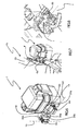
- the figure 1 is a front view from inside the engine compartment of a front face of a motor vehicle, this face mainly comprising a motorcycle fan unit and a structure supporting this motorcycle fan unit.
- the figure 2 is a front view of a clip for fixing an element to a structure according to one embodiment of the fixing device according to the invention.
- the figure 3 is a side view of this clip.
- the figure 4 is a top view of this clip.
- the figure 5 is a perspective view of this clip.
- FIGS. 6 and 9 are perspective views of an element intended to be fixed on a structure by means of a fixing device according to the invention.
- FIGS. 7 and 8 are perspective views of an element fixed to a structure by means of a fastening device according to the invention.
- the figure 10 is a sectional view, at a first fastening means, of an element attached to a structure.
- the figure 11 is a sectional view, at a second fastening means, of an element attached to a structure.
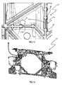
- the Figures 12 and 13 are views of a structure adapted to receive a fixing device according to the invention.
- FIG. figure 1 A portion of the front face 3 of a motor vehicle is shown in FIG. figure 1 .
- a nozzle-shaped structure 15 having an opening 23 in which is fixed, on the structure, a motorcycle fan unit 16. It also distinguishes an electrical harness 5 composed of different sleeves 4 and a relay housing 1 of motorcycle fan unit power supply. This housing has the particularity of being fixed to the structure.
- the fixing of the housing 1 on the structure 15 is provided by a fixing device 20 comprising a first fixing means 6a and a second fixing means 6b.
- a positioning means 24 makes it possible to position and / or orient the first and second fixing means with respect to one another.
- the term "set in position and / or orient relative to each other the first and second fastening means” block degrees of freedom of the first and second fastening means.
- all the degrees of freedom of the first fixing means are locked relative to the second fastening means and relative to the positioning means, the positioning means supporting the first and second fastening means.
- the first and second fixing means are integral with the positioning means, that is to say rigidly fixed to the positioning means.
- the positioning means is rigid, that is to say that under the effect of mechanical actions, it will very little deform unlike a passing sheath of a bundle of electric wire for example which will deform a lot, especially under bending stresses.
- the first and second fixing means act by pinching, that is to say that they comprise elements pinching pinch zones, for example ribs 7a, 7b, of the structure to which they must be fixed. . Fixing is then ensured by phenomena of friction and / or arching at the level of the pinching organ interfaces-pinch zones.
- the fixing means may consist of clips 6, 6a, 6b as shown in FIGS. Figures 2 to 5 .
- These clips are generally in the form of a U-profile with two wings 8 extending parallel and whose recess 9, formed between these wings, is intended to receive a nip 21a, 21b of the structure.
- a first set of elastic strips 10 extending opposite each other from the flanges and a second set of elastic strips 11 extending opposite each other from the flanges are provided in the recess of the U.
- These are the lamellae which come into contact and which exert, by their deformation, mechanical actions on the pinching zone of the structure. These mechanical actions then give rise to friction forces or even arches, opposing the withdrawal of the pinching zone of the hollow 9.
- the blades forming an angle with the wings the pinching zone can penetrate in the hollow easily.
- These staples are for example of the metallo-plastic type, with a U-shaped plastic profile and metal strips reported.
- the two wings are connected to each other by a base 30.
- This base has for example means for fixing the clip to the positioning means 24.
- These means comprise for example a first slide element, such as a pad 31 , 31 a, 31 b, intended to cooperate with a second slide member, such as a rail 32a, 32b of complementary shape to that of the pad, the second slide member being provided on the positioning means.
- These means still include a locking means such as a lug 33 provided at the end of an elastic tongue 34, 34a, 34b and intended to cooperate with a hole in the second slide member to prevent the movement of the two slide elements relative to the other and therefore their disassembly.
- the fixing means may be fixed, by any other removable connection or not, to the positioning means.
- they can be crimped or welded.
- the connection blocks all the degrees of freedom of the fixing means. This is not necessarily necessary.
- the degree of freedom of rotation of the fastening means along an axis perpendicular to their base can be preserved. In this case, it is the geometry of the structure on which the fixing device is intended to be fixed which determines the orientation of each of the fixing means.
- the two fastening means that is to say, in the case described, the two straight lines 13, 14 parallel to the bases 30 and extending along the longitudinal axes of the U-shaped profiles of the staples, form an angle acute higher than 30 °, in particular greater than 45 ° and preferably substantially equal to 90 °.
- the positioning means is intended to be attached to the element to be fixed. It can be reported by any means. It may also be from the element, especially when the element is or includes a housing.
- FIG. 12 and 13 The structure on which the element is to be fixed is shown in Figures 12 and 13 .
- This structure comprises ribs 7, including a rib 7a and a rib 7b, that the fixing means 6a and 6b must respectively pinch.
- the invention has been described above applied to the attachment of a power relay unit of a motorcycle fan unit on a structure supporting a motorcycle fan unit. Nevertheless, the invention can obviously be applied to any attachment of an element on a structure. Similarly, the embodiment described uses two fixing means, but it is possible for a fixing device according to the invention to use more than two fixing means.
Landscapes
- Engineering & Computer Science (AREA)
- General Engineering & Computer Science (AREA)
- Mechanical Engineering (AREA)
- Structures Of Non-Positive Displacement Pumps (AREA)
- Cooling Or The Like Of Electrical Apparatus (AREA)
- Connection Of Plates (AREA)
Description
La présente invention concerne un dispositif de fixation d'un élément, notamment un boîtier de relais d'alimentation d'un groupe moto ventilateur, sur une structure, notamment une buse supportant un groupe moto ventilateur dans un compartiment moteur d'un véhicule automobile. L'invention porte également sur un procédé d'assemblage d'un tel élément sur une telle structure. L'invention porte encore sur une structure apte à recevoir le dispositif de fixation.The present invention relates to a device for fixing an element, in particular a power supply relay box of a motorcycle fan unit, on a structure, in particular a nozzle supporting a motorcycle fan unit in an engine compartment of a motor vehicle. The invention also relates to a method of assembling such an element on such a structure. The invention further relates to a structure adapted to receive the fixing device.
Lors de la conception d'un véhicule automobile, il est courant de redéfinir la position d'un élément dans ce véhicule pour diverses raisons. Dans la situation ayant amené à la présente invention, il avait été demandé à des concepteurs d'un véhicule de déplacer un boîtier de relais d'alimentation d'un groupe moto ventilateur d'une position à proximité d'une batterie, d'un calculateur et d'un boîtier de fusibles du véhicule à une position à proximité du groupe moto ventilateur. Cependant, dans cette dernière position, il n'existe pas d'élément pouvant a priori supporter le poids du boîtier.When designing a motor vehicle, it is common to redefine the position of an element in this vehicle for various reasons. In the situation that led to the present invention, designers of a vehicle had been asked to move a power relay box of a motorcycle fan unit from a position near a battery, a computer and a fuse box of the vehicle at a position near the motorcycle fan unit. However, in this latter position, there is no element that can a priori support the weight of the housing.
Les documents
Le but de l'invention est donc de fournir un dispositif de fixation permettant le montage d'un élément sur un véhicule automobile. En particulier, l'invention propose un dispositif de fixation simple, bon marché et permettant un montage aisé, rapide et sans effort.The object of the invention is therefore to provide a fixing device for mounting an element on a motor vehicle. In In particular, the invention proposes a simple, inexpensive fastening device that allows assembly to be carried out easily, quickly and effortlessly.
Le dispositif selon l'invention permet de fixer un élément sur une structure II est caractérisé en ce qu'il comprend au moins un premier moyen de fixation destiné à agir par pincement sur une première nervure de la structure et un deuxième moyen de fixation destiné à agir par pincement sur une deuxième nervure de la structure, le dispositif comprenant un moyen de positionnement mettant en position et/ou orientant l'un par rapport à l'autre les premier et deuxième moyens de fixation.The device according to the invention makes it possible to fix an element on a structure II is characterized in that it comprises at least a first fixing means intended to act by pinching on a first rib of the structure and a second fixing means intended to act by pinching on a second rib of the structure, the device comprising a positioning means positioning and / or orienting relative to each other the first and second fixing means.
Le moyen de positionnement des premier et deuxième moyens l'un par rapport à l'autre peut être tel que les premier et deuxième moyens forment un angle aigu supérieur à 30° et, de préférence, supérieur à 45°.The positioning means of the first and second means relative to each other may be such that the first and second means form an acute angle greater than 30 ° and, preferably, greater than 45 °.
Le moyen de positionnement des premier et deuxième moyens l'un par rapport à l'autre peut être tel que les premier et deuxième moyens forment au moins sensiblement un angle droit.The positioning means of the first and second means relative to each other may be such that the first and second means form at least substantially a right angle.
Le moyen de positionnement peut faire partie de l'élément.The positioning means may be part of the element.
Les premier et deuxième moyens de fixation peuvent être des agrafes.The first and second fastening means may be staples.
L'élément peut être un boîtier de relais d'alimentation d'un groupe moto ventilateur de véhicule automobile.The element can be a power relay box of a motorcycle fan motor vehicle.
Selon l'invention, une structure comprend des nervures aptes à coopérer avec un dispositif de fixation défini précédemment.According to the invention, a structure comprises ribs adapted to cooperate with a fixing device defined above.
Les nervures peuvent comprendre des protubérances de détrompage.The ribs may include keying protuberances.
La structure peut consister en une buse destinée à supporter un groupe moto-ventilateur de véhicule automobile.The structure may consist of a nozzle intended to support a motorcycle fan unit of a motor vehicle.
Selon l'invention, un véhicule automobile comprend un dispositif défini précédemment.According to the invention, a motor vehicle comprises a device defined above.
Les dessins annexés représentent, à titre d'exemple, un mode de réalisation d'un dispositif selon l'invention.The accompanying drawings represent, by way of example, an embodiment of a device according to the invention.
La
La
La
La
La
Les
Les
La
La
Les
Une partie de face avant 3 de véhicule automobile est représentée à la
La fixation du boîtier 1 sur la structure 15 est assurée par un dispositif 20 de fixation comprenant un premier moyen de fixation 6a et un deuxième moyen de fixation 6b. Un moyen de positionnement 24 permet de mettre en position et/ou d'orienter l'un par rapport à l'autre les premier et deuxième moyens de fixation. On entend par « mettre en position et/ou d'orienter l'un par rapport à l'autre les premier et deuxième moyens de fixation » bloquer des degrés de liberté des premier et deuxième moyens de fixation. De préférence, tous les degrés de liberté du premier moyen de fixation sont bloqués par rapport au deuxième moyen de fixation et par rapport au moyen de positionnement, le moyen de positionnement supportant les premier et deuxième moyens de fixation. Dans ce cas, les premier et deuxième moyens de fixation sont solidaires du moyen de positionnement, c'est-à-dire rigidement fixés au moyen de positionnement. Le moyen de positionnement est rigide, c'est-à-dire que sous l'effet d'actions mécaniques, il va très peu se déformer contrairement à une gaine de passage d'un faisceau de fil électrique par exemple qui se déformera beaucoup, notamment sous des sollicitations de flexion.The fixing of the
De préférence, les premier et deuxième moyens de fixation agissent par pincement, c'est-à-dire qu'ils comprennent des organes pinçant des zones de pincement, par exemple des nervures 7a, 7b, de la structure à laquelle ils doivent se fixer. La fixation est ensuite assurée par des phénomènes de frottement et/ou d'arc-boutement au niveau des interfaces organes pinçant-zones de pincement.Preferably, the first and second fixing means act by pinching, that is to say that they comprise elements pinching pinch zones, for example ribs 7a, 7b, of the structure to which they must be fixed. . Fixing is then ensured by phenomena of friction and / or arching at the level of the pinching organ interfaces-pinch zones.
Par exemple, les moyens de fixation peuvent consister en des agrafes 6, 6a, 6b comme représentées aux
Les deux ailes sont reliées l'une à l'autre par une embase 30. Cette embase présente par exemple des moyens pour fixer l'agrafe au moyen de positionnement 24. Ces moyens comprennent par exemple un premier élément de glissière, comme un patin 31, 31 a, 31 b, destiné à coopérer avec un deuxième élément de glissière, comme un rail 32a, 32b de forme complémentaire à celle du patin, le deuxième élément de glissière étant prévu sur le moyen de positionnement. Ces moyens comprennent encore un moyen de verrouillage comme un ergot 33 prévu au bout d'une languette élastique 34, 34a, 34b et destiné à coopérer avec un trou dans le deuxième élément de glissière pour interdire le mouvement des deux éléments de glissière l'un par rapport à l'autre et donc leur démontage.The two wings are connected to each other by a
Les moyens de fixation peuvent être fixés, par toute autre liaison démontable ou non, au moyen de positionnement. Notamment, ils peuvent être sertis ou soudés. Dans l'exemple décrit précédemment, la liaison bloque tous les degrés de liberté des moyens de fixation. Cela n'est pas forcément nécessaire. Par exemple, le degré de liberté de rotation des moyens de fixation selon un axe perpendiculaire à leur embase peut être conservé. Dans ce cas, c'est la géométrie de la structure sur laquelle le dispositif de fixation est destiné à se fixer qui détermine l'orientation de chacun des moyens de fixation.The fixing means may be fixed, by any other removable connection or not, to the positioning means. In particular, they can be crimped or welded. In the example described above, the connection blocks all the degrees of freedom of the fixing means. This is not necessarily necessary. For example, the degree of freedom of rotation of the fastening means along an axis perpendicular to their base can be preserved. In this case, it is the geometry of the structure on which the fixing device is intended to be fixed which determines the orientation of each of the fixing means.
De préférence, les deux moyens de fixation, c'est-à-dire, dans le cas décrit, les deux droites 13, 14 parallèles aux embases 30 et s'étendant selon les axes longitudinaux des profils en U des agrafes, forment un angle aigu supérieur à 30°, en particulier, supérieur à 45° et, de préférence, sensiblement égal à 90°.Preferably, the two fastening means, that is to say, in the case described, the two
Le moyen de positionnement est destiné à être rapporté sur l'élément à fixer. Il peut y être rapporté par tout moyen. Il peut être aussi venu de l'élément, notamment lorsque l'élément est ou comprend un boîtier.The positioning means is intended to be attached to the element to be fixed. It can be reported by any means. It may also be from the element, especially when the element is or includes a housing.
La structure sur laquelle doit être fixé l'élément est représentée aux
Afin d'assurer une fixation aussi efficace que possible, il est recommande de prévoir une distance aussi élevée entre les deux moyens de fixation.In order to ensure as effective a fixation as possible, it is recommended to provide such a high distance between the two fastening means.
Selon l'invention, pour fixer un élément sur une structure, on procède comme suit :
- on fournit au moins deux moyens de fixation,
- on rapporte ces moyens de fixation sur un moyen de positionnement, celui-ci faisant éventuellement partie de l'élément,
- on déplace l'élément en translation par rapport à la structure de sorte à faire coopérer des nervures de la structure avec les moyens de fixation, en particulier de sorte à ce que des nervures pénètrent dans les moyens de fixation.
- at least two fixing means are provided,
- these fixing means are reported on a positioning means, which may be part of the element,
- the element is moved in translation relative to the structure so as to cooperate ribs of the structure with the fastening means, in particular so that ribs penetrate the fastening means.
L'invention a été décrite ci-dessus appliquée à la fixation d'un boîtier de relais d'alimentation d'un groupe moto ventilateur sur une structure supportant un groupe moto ventilateur. Néanmoins, l'invention peut évidemment être appliquée à toute fixation d'un élément sur une structure. De même, le mode de réalisation décrit utilise deux moyens de fixation, mais il est possible qu'un dispositif de fixation selon l'invention utilise plus de deux moyens de fixation.The invention has been described above applied to the attachment of a power relay unit of a motorcycle fan unit on a structure supporting a motorcycle fan unit. Nevertheless, the invention can obviously be applied to any attachment of an element on a structure. Similarly, the embodiment described uses two fixing means, but it is possible for a fixing device according to the invention to use more than two fixing means.
Claims (5)
- Automobile vehicle front panel structure consisting of an air funnel adapted to support an electric fan (16) of the vehicle, characterized in that it includes a device (20) for fixing a relay box (1) for powering the electric fan (16) and in that it includes ribs (7a, 7b) cooperating with said fixing device (20), the device (20) including at least first fixing means (6a) adapted to be clamped onto a first rib (7a) of the structure and second fixing means (6b) adapted to be clamped onto a second rib (7b) of the structure, the device (20) including positioning means (24) for positioning and/or orienting the first and second fixing means (6a, 6b) relative to each other, the latter means consisting of clips (6) taking the form of a U-section with two flanges (8) joined together by a base (30) including means for fixing the clip to the positioning means (24), these means including first and second slide elements, said first slide element forming a skid (31, 31a, 31b) co-operating with said second slide element forming a rail (32a, 32b) of complementary shape to that of the skid and further including locking means forming a lug (33) adapted to co-operate with a hole in the second slide element to prevent movement of the two slide elements relative to each other.
- Structure according to Claim 1, characterized in that the means for positioning the first and second means relative to each other are such that the first and second means form an acute angle (α) greater than 30° and preferably greater than 45°.
- Structure according to Claim 2, characterized in that the means for positioning the first and second means relative to each other are such that the first and second means form at least substantially a right angle.
- Structure according to any one of the preceding claims, characterized in that the positioning means are part of the relay box (1).
- Structure according to any one of the preceding claims, characterized in that the ribs (7a, 7b) include polarizer protuberances (22).
Applications Claiming Priority (2)
| Application Number | Priority Date | Filing Date | Title |
|---|---|---|---|
| FR0804908A FR2935765B1 (en) | 2008-09-08 | 2008-09-08 | DEVICE FOR FIXING A POWER SUPPLY RELAY HOUSING OF A MOTORBIKE GROUP ON A NOZZLE SUPPORTING A MOTORBIKE GROUP OF A MOTOR VEHICLE. |
| PCT/FR2009/051680 WO2010026353A1 (en) | 2008-09-08 | 2009-09-07 | Device for attaching a power supply relay housing of a motor-fan system onto a nozzle supporting an automobile motor-fan system |
Publications (2)
| Publication Number | Publication Date |
|---|---|
| EP2321540A1 EP2321540A1 (en) | 2011-05-18 |
| EP2321540B1 true EP2321540B1 (en) | 2013-08-28 |
Family
ID=40433615
Family Applications (1)
| Application Number | Title | Priority Date | Filing Date |
|---|---|---|---|
| EP09741377.7A Active EP2321540B1 (en) | 2008-09-08 | 2009-09-07 | Structure suporting an automobile motor-fan system and device for attaching a power supply relay housing of said motor-fan system onto said structure. |
Country Status (5)
| Country | Link |
|---|---|
| EP (1) | EP2321540B1 (en) |
| BR (1) | BRPI0918245B1 (en) |
| FR (1) | FR2935765B1 (en) |
| RU (1) | RU2527707C2 (en) |
| WO (1) | WO2010026353A1 (en) |
Family Cites Families (7)
| Publication number | Priority date | Publication date | Assignee | Title |
|---|---|---|---|---|
| GB729844A (en) * | 1952-02-01 | 1955-05-11 | Miag Muehlenbau & Ind Gmbh | Improvements in or relating to safety devices for machinery |
| US4259767A (en) * | 1979-07-09 | 1981-04-07 | Eaton Corporation | Fastener |
| AU534139B2 (en) * | 1980-04-11 | 1984-01-05 | Surface Installations Limited | Structural systems |
| JP3830072B2 (en) * | 1999-12-10 | 2006-10-04 | 矢崎総業株式会社 | Electrical junction box mounting structure |
| NL1026278C2 (en) * | 2004-05-27 | 2005-11-30 | Steven Edward Kelly | Structure element, basic element, holding means and aid for manufacturing a reinforcement, method for constructing such an aid and method for manufacturing a reinforcement. |
| US7418994B2 (en) * | 2004-06-11 | 2008-09-02 | Deere & Company | Fan shroud with integral hood seal |
| DE102006023042A1 (en) * | 2006-05-17 | 2007-11-29 | Bayerische Motoren Werke Ag | Fixture component/sub-assembly for clamping on to devices, has two mutually spaced-apart clamp- or clip-sections |
-
2008
- 2008-09-08 FR FR0804908A patent/FR2935765B1/en not_active Expired - Fee Related
-
2009
- 2009-09-07 EP EP09741377.7A patent/EP2321540B1/en active Active
- 2009-09-07 WO PCT/FR2009/051680 patent/WO2010026353A1/en active Application Filing
- 2009-09-07 BR BRPI0918245-4A patent/BRPI0918245B1/en not_active IP Right Cessation
- 2009-09-07 RU RU2011113549/12A patent/RU2527707C2/en active
Also Published As
| Publication number | Publication date |
|---|---|
| BRPI0918245A2 (en) | 2015-12-15 |
| BRPI0918245B1 (en) | 2019-06-04 |
| FR2935765A1 (en) | 2010-03-12 |
| RU2527707C2 (en) | 2014-09-10 |
| RU2011113549A (en) | 2012-10-20 |
| EP2321540A1 (en) | 2011-05-18 |
| FR2935765B1 (en) | 2017-07-14 |
| WO2010026353A1 (en) | 2010-03-11 |
Similar Documents
| Publication | Publication Date | Title |
|---|---|---|
| EP1937524B1 (en) | Connector for mounting and jointing a wiper blade to a driving arm end | |
| EP2707257B1 (en) | Connection mount, mechanical connector and wiping device for a motor vehicle | |
| EP2300284B1 (en) | Windscreen wiper system, particularly for a motor vehicle | |
| EP2200851B1 (en) | Motor vehicle front end module | |
| EP1457390B1 (en) | Sensor support of a motor vehicle | |
| FR2937099A1 (en) | FIXING SYSTEM, IN PARTICULAR FOR FIXING SEATS IN A VEHICLE AND, MORE PARTICULARLY, IN AN AIRCRAFT | |
| FR2730521A1 (en) | WINDOW REGULATOR | |
| WO2012095194A1 (en) | Device and assembly for supporting a pair of windshield wipers, and corresponding packaging and assembly method | |
| FR2762557A1 (en) | ARTICLE COMPRISING TWO ELEMENTS ARTICULATED ONE IN RELATION TO THE OTHER | |
| EP2321540B1 (en) | Structure suporting an automobile motor-fan system and device for attaching a power supply relay housing of said motor-fan system onto said structure. | |
| EP2900525B1 (en) | Device for actuating a driving arm of a wiper, in particular for the rear window of a vehicle, and wiping system equipped with such a device | |
| FR3130705A1 (en) | Vehicle seat slider and assembly comprising the slider | |
| FR2935652A1 (en) | Electric cable arrangement for engine compartment of motor vehicle, has electric cable comprising central section extending transversally from proximal section into raceway, where central section is retained in raceway by retaining unit | |
| EP3849845A1 (en) | Device for attaching a trim to a motor vehicle bodywork structure such as a window post | |
| EP0547929A1 (en) | Electrical socket, in particular for automotive vehicles | |
| EP1598241A1 (en) | Arrangement of a trim element on its support inside of a vehicle | |
| EP3792118B1 (en) | Trim component for a steering column of a motor vehicle | |
| FR3075724A1 (en) | COVER UNIT FOR A MOTOR VEHICLE | |
| EP2116446B1 (en) | Support for fixing an element for covering part of the body of a vehicle, corresponding covering element and use of such a fixing support | |
| EP1834838B1 (en) | Device for quickly fitting accessories on the headliner of a vehicle | |
| EP3254903B1 (en) | Part for attaching trim elements to a side structure element of a motor vehicle | |
| EP3248848B1 (en) | Securing device for fitting a windscreen wiper on a drive arm, and corresponding wiping system | |
| EP3762279A1 (en) | Multifunctional wheel housing reinforcement | |
| FR2742816A1 (en) | System of fixing control module for fan in air duct of air conditioning system for motor vehicles | |
| EP3046810B1 (en) | Front structure of motor vehicle comprising an electric cable |
Legal Events
| Date | Code | Title | Description |
|---|---|---|---|
| PUAI | Public reference made under article 153(3) epc to a published international application that has entered the european phase |
Free format text: ORIGINAL CODE: 0009012 |
|
| 17P | Request for examination filed |
Effective date: 20110214 |
|
| AK | Designated contracting states |
Kind code of ref document: A1 Designated state(s): AT BE BG CH CY CZ DE DK EE ES FI FR GB GR HR HU IE IS IT LI LT LU LV MC MK MT NL NO PL PT RO SE SI SK SM TR |
|
| AX | Request for extension of the european patent |
Extension state: AL BA RS |
|
| DAX | Request for extension of the european patent (deleted) | ||
| 17Q | First examination report despatched |
Effective date: 20130403 |
|
| GRAP | Despatch of communication of intention to grant a patent |
Free format text: ORIGINAL CODE: EPIDOSNIGR1 |
|
| INTG | Intention to grant announced |
Effective date: 20130606 |
|
| GRAS | Grant fee paid |
Free format text: ORIGINAL CODE: EPIDOSNIGR3 |
|
| GRAA | (expected) grant |
Free format text: ORIGINAL CODE: 0009210 |
|
| AK | Designated contracting states |
Kind code of ref document: B1 Designated state(s): AT BE BG CH CY CZ DE DK EE ES FI FR GB GR HR HU IE IS IT LI LT LU LV MC MK MT NL NO PL PT RO SE SI SK SM TR |
|
| REG | Reference to a national code |
Ref country code: GB Ref legal event code: FG4D Free format text: NOT ENGLISH |
|
| REG | Reference to a national code |
Ref country code: CH Ref legal event code: EP |
|
| REG | Reference to a national code |
Ref country code: AT Ref legal event code: REF Ref document number: 629528 Country of ref document: AT Kind code of ref document: T Effective date: 20130915 |
|
| REG | Reference to a national code |
Ref country code: IE Ref legal event code: FG4D Free format text: LANGUAGE OF EP DOCUMENT: FRENCH |
|
| REG | Reference to a national code |
Ref country code: DE Ref legal event code: R096 Ref document number: 602009018376 Country of ref document: DE Effective date: 20131024 |
|
| REG | Reference to a national code |
Ref country code: AT Ref legal event code: MK05 Ref document number: 629528 Country of ref document: AT Kind code of ref document: T Effective date: 20130828 |
|
| REG | Reference to a national code |
Ref country code: LT Ref legal event code: MG4D |
|
| REG | Reference to a national code |
Ref country code: NL Ref legal event code: VDEP Effective date: 20130828 |
|
| PG25 | Lapsed in a contracting state [announced via postgrant information from national office to epo] |
Ref country code: AT Free format text: LAPSE BECAUSE OF FAILURE TO SUBMIT A TRANSLATION OF THE DESCRIPTION OR TO PAY THE FEE WITHIN THE PRESCRIBED TIME-LIMIT Effective date: 20130828 Ref country code: CY Free format text: LAPSE BECAUSE OF FAILURE TO SUBMIT A TRANSLATION OF THE DESCRIPTION OR TO PAY THE FEE WITHIN THE PRESCRIBED TIME-LIMIT Effective date: 20130717 Ref country code: HR Free format text: LAPSE BECAUSE OF FAILURE TO SUBMIT A TRANSLATION OF THE DESCRIPTION OR TO PAY THE FEE WITHIN THE PRESCRIBED TIME-LIMIT Effective date: 20130828 Ref country code: IS Free format text: LAPSE BECAUSE OF FAILURE TO SUBMIT A TRANSLATION OF THE DESCRIPTION OR TO PAY THE FEE WITHIN THE PRESCRIBED TIME-LIMIT Effective date: 20131228 Ref country code: LT Free format text: LAPSE BECAUSE OF FAILURE TO SUBMIT A TRANSLATION OF THE DESCRIPTION OR TO PAY THE FEE WITHIN THE PRESCRIBED TIME-LIMIT Effective date: 20130828 Ref country code: PT Free format text: LAPSE BECAUSE OF FAILURE TO SUBMIT A TRANSLATION OF THE DESCRIPTION OR TO PAY THE FEE WITHIN THE PRESCRIBED TIME-LIMIT Effective date: 20131230 Ref country code: NO Free format text: LAPSE BECAUSE OF FAILURE TO SUBMIT A TRANSLATION OF THE DESCRIPTION OR TO PAY THE FEE WITHIN THE PRESCRIBED TIME-LIMIT Effective date: 20131128 Ref country code: SE Free format text: LAPSE BECAUSE OF FAILURE TO SUBMIT A TRANSLATION OF THE DESCRIPTION OR TO PAY THE FEE WITHIN THE PRESCRIBED TIME-LIMIT Effective date: 20130828 |
|
| REG | Reference to a national code |
Ref country code: NL Ref legal event code: VDEP Effective date: 20130828 |
|
| PG25 | Lapsed in a contracting state [announced via postgrant information from national office to epo] |
Ref country code: LV Free format text: LAPSE BECAUSE OF FAILURE TO SUBMIT A TRANSLATION OF THE DESCRIPTION OR TO PAY THE FEE WITHIN THE PRESCRIBED TIME-LIMIT Effective date: 20130828 Ref country code: PL Free format text: LAPSE BECAUSE OF FAILURE TO SUBMIT A TRANSLATION OF THE DESCRIPTION OR TO PAY THE FEE WITHIN THE PRESCRIBED TIME-LIMIT Effective date: 20130828 Ref country code: GR Free format text: LAPSE BECAUSE OF FAILURE TO SUBMIT A TRANSLATION OF THE DESCRIPTION OR TO PAY THE FEE WITHIN THE PRESCRIBED TIME-LIMIT Effective date: 20131129 Ref country code: FI Free format text: LAPSE BECAUSE OF FAILURE TO SUBMIT A TRANSLATION OF THE DESCRIPTION OR TO PAY THE FEE WITHIN THE PRESCRIBED TIME-LIMIT Effective date: 20130828 Ref country code: SI Free format text: LAPSE BECAUSE OF FAILURE TO SUBMIT A TRANSLATION OF THE DESCRIPTION OR TO PAY THE FEE WITHIN THE PRESCRIBED TIME-LIMIT Effective date: 20130828 |
|
| BERE | Be: lapsed |
Owner name: RENAULT S.A.S. Effective date: 20130930 |
|
| PG25 | Lapsed in a contracting state [announced via postgrant information from national office to epo] |
Ref country code: CY Free format text: LAPSE BECAUSE OF FAILURE TO SUBMIT A TRANSLATION OF THE DESCRIPTION OR TO PAY THE FEE WITHIN THE PRESCRIBED TIME-LIMIT Effective date: 20130828 |
|
| PG25 | Lapsed in a contracting state [announced via postgrant information from national office to epo] |
Ref country code: SK Free format text: LAPSE BECAUSE OF FAILURE TO SUBMIT A TRANSLATION OF THE DESCRIPTION OR TO PAY THE FEE WITHIN THE PRESCRIBED TIME-LIMIT Effective date: 20130828 Ref country code: NL Free format text: LAPSE BECAUSE OF FAILURE TO SUBMIT A TRANSLATION OF THE DESCRIPTION OR TO PAY THE FEE WITHIN THE PRESCRIBED TIME-LIMIT Effective date: 20130828 Ref country code: DK Free format text: LAPSE BECAUSE OF FAILURE TO SUBMIT A TRANSLATION OF THE DESCRIPTION OR TO PAY THE FEE WITHIN THE PRESCRIBED TIME-LIMIT Effective date: 20130828 Ref country code: EE Free format text: LAPSE BECAUSE OF FAILURE TO SUBMIT A TRANSLATION OF THE DESCRIPTION OR TO PAY THE FEE WITHIN THE PRESCRIBED TIME-LIMIT Effective date: 20130828 Ref country code: RO Free format text: LAPSE BECAUSE OF FAILURE TO SUBMIT A TRANSLATION OF THE DESCRIPTION OR TO PAY THE FEE WITHIN THE PRESCRIBED TIME-LIMIT Effective date: 20130828 Ref country code: CZ Free format text: LAPSE BECAUSE OF FAILURE TO SUBMIT A TRANSLATION OF THE DESCRIPTION OR TO PAY THE FEE WITHIN THE PRESCRIBED TIME-LIMIT Effective date: 20130828 |
|
| REG | Reference to a national code |
Ref country code: CH Ref legal event code: PL |
|
| PG25 | Lapsed in a contracting state [announced via postgrant information from national office to epo] |
Ref country code: MC Free format text: LAPSE BECAUSE OF FAILURE TO SUBMIT A TRANSLATION OF THE DESCRIPTION OR TO PAY THE FEE WITHIN THE PRESCRIBED TIME-LIMIT Effective date: 20130828 Ref country code: IT Free format text: LAPSE BECAUSE OF FAILURE TO SUBMIT A TRANSLATION OF THE DESCRIPTION OR TO PAY THE FEE WITHIN THE PRESCRIBED TIME-LIMIT Effective date: 20130828 Ref country code: ES Free format text: LAPSE BECAUSE OF FAILURE TO SUBMIT A TRANSLATION OF THE DESCRIPTION OR TO PAY THE FEE WITHIN THE PRESCRIBED TIME-LIMIT Effective date: 20130828 |
|
| REG | Reference to a national code |
Ref country code: DE Ref legal event code: R097 Ref document number: 602009018376 Country of ref document: DE |
|
| REG | Reference to a national code |
Ref country code: IE Ref legal event code: MM4A |
|
| PLBE | No opposition filed within time limit |
Free format text: ORIGINAL CODE: 0009261 |
|
| STAA | Information on the status of an ep patent application or granted ep patent |
Free format text: STATUS: NO OPPOSITION FILED WITHIN TIME LIMIT |
|
| PG25 | Lapsed in a contracting state [announced via postgrant information from national office to epo] |
Ref country code: IE Free format text: LAPSE BECAUSE OF NON-PAYMENT OF DUE FEES Effective date: 20130907 Ref country code: LI Free format text: LAPSE BECAUSE OF NON-PAYMENT OF DUE FEES Effective date: 20130930 Ref country code: BE Free format text: LAPSE BECAUSE OF NON-PAYMENT OF DUE FEES Effective date: 20130930 Ref country code: CH Free format text: LAPSE BECAUSE OF NON-PAYMENT OF DUE FEES Effective date: 20130930 |
|
| 26N | No opposition filed |
Effective date: 20140530 |
|
| REG | Reference to a national code |
Ref country code: DE Ref legal event code: R097 Ref document number: 602009018376 Country of ref document: DE Effective date: 20140530 |
|
| PG25 | Lapsed in a contracting state [announced via postgrant information from national office to epo] |
Ref country code: SM Free format text: LAPSE BECAUSE OF FAILURE TO SUBMIT A TRANSLATION OF THE DESCRIPTION OR TO PAY THE FEE WITHIN THE PRESCRIBED TIME-LIMIT Effective date: 20130828 |
|
| PG25 | Lapsed in a contracting state [announced via postgrant information from national office to epo] |
Ref country code: TR Free format text: LAPSE BECAUSE OF FAILURE TO SUBMIT A TRANSLATION OF THE DESCRIPTION OR TO PAY THE FEE WITHIN THE PRESCRIBED TIME-LIMIT Effective date: 20130828 Ref country code: MT Free format text: LAPSE BECAUSE OF FAILURE TO SUBMIT A TRANSLATION OF THE DESCRIPTION OR TO PAY THE FEE WITHIN THE PRESCRIBED TIME-LIMIT Effective date: 20130828 |
|
| PG25 | Lapsed in a contracting state [announced via postgrant information from national office to epo] |
Ref country code: HU Free format text: LAPSE BECAUSE OF FAILURE TO SUBMIT A TRANSLATION OF THE DESCRIPTION OR TO PAY THE FEE WITHIN THE PRESCRIBED TIME-LIMIT; INVALID AB INITIO Effective date: 20090907 Ref country code: BG Free format text: LAPSE BECAUSE OF FAILURE TO SUBMIT A TRANSLATION OF THE DESCRIPTION OR TO PAY THE FEE WITHIN THE PRESCRIBED TIME-LIMIT Effective date: 20130828 Ref country code: MK Free format text: LAPSE BECAUSE OF FAILURE TO SUBMIT A TRANSLATION OF THE DESCRIPTION OR TO PAY THE FEE WITHIN THE PRESCRIBED TIME-LIMIT Effective date: 20130828 Ref country code: LU Free format text: LAPSE BECAUSE OF NON-PAYMENT OF DUE FEES Effective date: 20130907 |
|
| REG | Reference to a national code |
Ref country code: FR Ref legal event code: PLFP Year of fee payment: 8 |
|
| REG | Reference to a national code |
Ref country code: FR Ref legal event code: PLFP Year of fee payment: 9 |
|
| REG | Reference to a national code |
Ref country code: FR Ref legal event code: PLFP Year of fee payment: 10 |
|
| PGFP | Annual fee paid to national office [announced via postgrant information from national office to epo] |
Ref country code: GB Payment date: 20210920 Year of fee payment: 13 |
|
| GBPC | Gb: european patent ceased through non-payment of renewal fee |
Effective date: 20220907 |
|
| P01 | Opt-out of the competence of the unified patent court (upc) registered |
Effective date: 20230608 |
|
| PG25 | Lapsed in a contracting state [announced via postgrant information from national office to epo] |
Ref country code: GB Free format text: LAPSE BECAUSE OF NON-PAYMENT OF DUE FEES Effective date: 20220907 |
|
| PGFP | Annual fee paid to national office [announced via postgrant information from national office to epo] |
Ref country code: FR Payment date: 20230928 Year of fee payment: 15 Ref country code: DE Payment date: 20230920 Year of fee payment: 15 |