EP2321086B1 - Halteeinrichtung für bolzen, fügekopf und verfahren - Google Patents
Halteeinrichtung für bolzen, fügekopf und verfahren Download PDFInfo
- Publication number
- EP2321086B1 EP2321086B1 EP09776620.8A EP09776620A EP2321086B1 EP 2321086 B1 EP2321086 B1 EP 2321086B1 EP 09776620 A EP09776620 A EP 09776620A EP 2321086 B1 EP2321086 B1 EP 2321086B1
- Authority
- EP
- European Patent Office
- Prior art keywords
- securing
- section
- clamping
- stud
- holding device
- Prior art date
- Legal status (The legal status is an assumption and is not a legal conclusion. Google has not performed a legal analysis and makes no representation as to the accuracy of the status listed.)
- Active
Links
Images



Classifications
-
- B—PERFORMING OPERATIONS; TRANSPORTING
- B65—CONVEYING; PACKING; STORING; HANDLING THIN OR FILAMENTARY MATERIAL
- B65G—TRANSPORT OR STORAGE DEVICES, e.g. CONVEYORS FOR LOADING OR TIPPING, SHOP CONVEYOR SYSTEMS OR PNEUMATIC TUBE CONVEYORS
- B65G51/00—Conveying articles through pipes or tubes by fluid flow or pressure; Conveying articles over a flat surface, e.g. the base of a trough, by jets located in the surface
- B65G51/02—Directly conveying the articles, e.g. slips, sheets, stockings, containers or workpieces, by flowing gases
-
- B—PERFORMING OPERATIONS; TRANSPORTING
- B23—MACHINE TOOLS; METAL-WORKING NOT OTHERWISE PROVIDED FOR
- B23K—SOLDERING OR UNSOLDERING; WELDING; CLADDING OR PLATING BY SOLDERING OR WELDING; CUTTING BY APPLYING HEAT LOCALLY, e.g. FLAME CUTTING; WORKING BY LASER BEAM
- B23K11/00—Resistance welding; Severing by resistance heating
- B23K11/002—Resistance welding; Severing by resistance heating specially adapted for particular articles or work
- B23K11/004—Welding of a small piece to a large or broad piece
- B23K11/0046—Welding of a small piece to a large or broad piece the extremity of a small piece being welded to a base, e.g. cooling studs or fins to tubes or plates
- B23K11/0053—Stud welding, i.e. resistive
-
- B—PERFORMING OPERATIONS; TRANSPORTING
- B23—MACHINE TOOLS; METAL-WORKING NOT OTHERWISE PROVIDED FOR
- B23K—SOLDERING OR UNSOLDERING; WELDING; CLADDING OR PLATING BY SOLDERING OR WELDING; CUTTING BY APPLYING HEAT LOCALLY, e.g. FLAME CUTTING; WORKING BY LASER BEAM
- B23K9/00—Arc welding or cutting
- B23K9/20—Stud welding
- B23K9/201—Stud welding of the extremity of a small piece on a large basis
-
- B—PERFORMING OPERATIONS; TRANSPORTING
- B23—MACHINE TOOLS; METAL-WORKING NOT OTHERWISE PROVIDED FOR
- B23K—SOLDERING OR UNSOLDERING; WELDING; CLADDING OR PLATING BY SOLDERING OR WELDING; CUTTING BY APPLYING HEAT LOCALLY, e.g. FLAME CUTTING; WORKING BY LASER BEAM
- B23K9/00—Arc welding or cutting
- B23K9/20—Stud welding
- B23K9/206—Stud welding with automatic stud supply
-
- B—PERFORMING OPERATIONS; TRANSPORTING
- B23—MACHINE TOOLS; METAL-WORKING NOT OTHERWISE PROVIDED FOR
- B23P—METAL-WORKING NOT OTHERWISE PROVIDED FOR; COMBINED OPERATIONS; UNIVERSAL MACHINE TOOLS
- B23P19/00—Machines for simply fitting together or separating metal parts or objects, or metal and non-metal parts, whether or not involving some deformation; Tools or devices therefor so far as not provided for in other classes
- B23P19/001—Article feeders for assembling machines
- B23P19/006—Holding or positioning the article in front of the applying tool
-
- Y—GENERAL TAGGING OF NEW TECHNOLOGICAL DEVELOPMENTS; GENERAL TAGGING OF CROSS-SECTIONAL TECHNOLOGIES SPANNING OVER SEVERAL SECTIONS OF THE IPC; TECHNICAL SUBJECTS COVERED BY FORMER USPC CROSS-REFERENCE ART COLLECTIONS [XRACs] AND DIGESTS
- Y10—TECHNICAL SUBJECTS COVERED BY FORMER USPC
- Y10T—TECHNICAL SUBJECTS COVERED BY FORMER US CLASSIFICATION
- Y10T29/00—Metal working
- Y10T29/53—Means to assemble or disassemble
- Y10T29/53709—Overedge assembling means
- Y10T29/53783—Clip applier
-
- Y—GENERAL TAGGING OF NEW TECHNOLOGICAL DEVELOPMENTS; GENERAL TAGGING OF CROSS-SECTIONAL TECHNOLOGIES SPANNING OVER SEVERAL SECTIONS OF THE IPC; TECHNICAL SUBJECTS COVERED BY FORMER USPC CROSS-REFERENCE ART COLLECTIONS [XRACs] AND DIGESTS
- Y10—TECHNICAL SUBJECTS COVERED BY FORMER USPC
- Y10T—TECHNICAL SUBJECTS COVERED BY FORMER US CLASSIFICATION
- Y10T29/00—Metal working
- Y10T29/53—Means to assemble or disassemble
- Y10T29/53909—Means comprising hand manipulatable tool
-
- Y—GENERAL TAGGING OF NEW TECHNOLOGICAL DEVELOPMENTS; GENERAL TAGGING OF CROSS-SECTIONAL TECHNOLOGIES SPANNING OVER SEVERAL SECTIONS OF THE IPC; TECHNICAL SUBJECTS COVERED BY FORMER USPC CROSS-REFERENCE ART COLLECTIONS [XRACs] AND DIGESTS
- Y10—TECHNICAL SUBJECTS COVERED BY FORMER USPC
- Y10T—TECHNICAL SUBJECTS COVERED BY FORMER US CLASSIFICATION
- Y10T29/00—Metal working
- Y10T29/53—Means to assemble or disassemble
- Y10T29/53909—Means comprising hand manipulatable tool
- Y10T29/53943—Hand gripper for direct push or pull
-
- Y—GENERAL TAGGING OF NEW TECHNOLOGICAL DEVELOPMENTS; GENERAL TAGGING OF CROSS-SECTIONAL TECHNOLOGIES SPANNING OVER SEVERAL SECTIONS OF THE IPC; TECHNICAL SUBJECTS COVERED BY FORMER USPC CROSS-REFERENCE ART COLLECTIONS [XRACs] AND DIGESTS
- Y10—TECHNICAL SUBJECTS COVERED BY FORMER USPC
- Y10T—TECHNICAL SUBJECTS COVERED BY FORMER US CLASSIFICATION
- Y10T29/00—Metal working
- Y10T29/53—Means to assemble or disassemble
- Y10T29/53909—Means comprising hand manipulatable tool
- Y10T29/53943—Hand gripper for direct push or pull
- Y10T29/53952—Tube sleeve or ferrule applying or removing
-
- Y—GENERAL TAGGING OF NEW TECHNOLOGICAL DEVELOPMENTS; GENERAL TAGGING OF CROSS-SECTIONAL TECHNOLOGIES SPANNING OVER SEVERAL SECTIONS OF THE IPC; TECHNICAL SUBJECTS COVERED BY FORMER USPC CROSS-REFERENCE ART COLLECTIONS [XRACs] AND DIGESTS
- Y10—TECHNICAL SUBJECTS COVERED BY FORMER USPC
- Y10T—TECHNICAL SUBJECTS COVERED BY FORMER US CLASSIFICATION
- Y10T29/00—Metal working
- Y10T29/53—Means to assemble or disassemble
- Y10T29/53961—Means to assemble or disassemble with work-holder for assembly
-
- Y—GENERAL TAGGING OF NEW TECHNOLOGICAL DEVELOPMENTS; GENERAL TAGGING OF CROSS-SECTIONAL TECHNOLOGIES SPANNING OVER SEVERAL SECTIONS OF THE IPC; TECHNICAL SUBJECTS COVERED BY FORMER USPC CROSS-REFERENCE ART COLLECTIONS [XRACs] AND DIGESTS
- Y10—TECHNICAL SUBJECTS COVERED BY FORMER USPC
- Y10T—TECHNICAL SUBJECTS COVERED BY FORMER US CLASSIFICATION
- Y10T29/00—Metal working
- Y10T29/53—Means to assemble or disassemble
- Y10T29/53978—Means to assemble or disassemble including means to relatively position plural work parts
-
- Y—GENERAL TAGGING OF NEW TECHNOLOGICAL DEVELOPMENTS; GENERAL TAGGING OF CROSS-SECTIONAL TECHNOLOGIES SPANNING OVER SEVERAL SECTIONS OF THE IPC; TECHNICAL SUBJECTS COVERED BY FORMER USPC CROSS-REFERENCE ART COLLECTIONS [XRACs] AND DIGESTS
- Y10—TECHNICAL SUBJECTS COVERED BY FORMER USPC
- Y10T—TECHNICAL SUBJECTS COVERED BY FORMER US CLASSIFICATION
- Y10T29/00—Metal working
- Y10T29/53—Means to assemble or disassemble
- Y10T29/53987—Tube, sleeve or ferrule
-
- Y—GENERAL TAGGING OF NEW TECHNOLOGICAL DEVELOPMENTS; GENERAL TAGGING OF CROSS-SECTIONAL TECHNOLOGIES SPANNING OVER SEVERAL SECTIONS OF THE IPC; TECHNICAL SUBJECTS COVERED BY FORMER USPC CROSS-REFERENCE ART COLLECTIONS [XRACs] AND DIGESTS
- Y10—TECHNICAL SUBJECTS COVERED BY FORMER USPC
- Y10T—TECHNICAL SUBJECTS COVERED BY FORMER US CLASSIFICATION
- Y10T29/00—Metal working
- Y10T29/53—Means to assemble or disassemble
- Y10T29/53991—Work gripper, anvil, or element
Definitions
- Such a holding device is also from the document EP 1 495 828 B1 known.
- the holding device is also assigned a centering device which can be introduced from above into the insertion section and into the securing device and is designed to align or engage a shank portion of the bolt.
- the bolt in the securing position need not be completely aligned with the joining axis, so that the holding device can be performed with comparatively large tolerances.
- the securing device prevents the bolt in the holding device in an excessive inclined position, in which a centering device is not able to align the shank portion of the bolt. Also in this case, the bolt would have to be ejected without the securing device according to the invention.
- the above object is further achieved in the above-mentioned holding device according to a second aspect, in that the securing device comprises a plurality of radially elastic support elements distributed over a circumference of the collet component in the form of a wire, wherein in a rest position of the support elements a bending section within the Collet component is located and thus reduces a free cross-section within the collet member, wherein the radially elastic support members move back to the rest position when the flange has passed the bending sections, wherein correspondingly an elasticity of the support elements is to be selected so that a bolt is not the support elements can bounce alone with its weight, wherein the support elements support a shank portion of the bolt in the securing position so that it does not come to rest on the collet component and of the shaft tensioner can be safely gripped, see claim 8.
- the object according to the first aspect is further achieved by a method for feeding a bolt to a joining head, which serves for joining the bolt to a workpiece, wherein the bolt has a radially projecting flange section, comprising the steps of: feeding the bolt into a holding device the joining head, until the flange portion is arranged in front of a chucking portion of the holding device, and securing the bolt in this position by a securing means having at least two radially mutually movable securing sleeve sections, which are formed as separate components and together form a securing sleeve, engages behind the flange portion , see claim 10.
- the securing sleeve is formed so that the flange portion can be passed through the securing sleeve.
- the flange portion when passing through the securing device is generally surrounded by the securing sleeve, so that it can be avoided that the flange portion (which may be polygonal, for example) is caught on contours of the securing device.
- the securing ends can engage behind the flange section of the flange section guided through the securing sleeve in order to establish the securing position.
- collet component clamping arms which form the clamping portion, and stop arms, which are axially longer than the clamping arms.
- the joining head has a shaft tensioning device, which is insertable into the holding device and adapted to receive the shank portion of a bolt in the securing position.
- the radial clamping force for holding the bolt in the ready position is generated by a radial clamping force of the clamping arms from the outside to the shaft tensioning device. This force is then, when the flange portion is axially pushed past the clamping arms, in the prior art, in some cases not yet sufficient to hold the bolt securely. In this case, prevent the Stopparme falling out of the bolt. Then the clamping arms come to the outside of the shaft tensioning device in plant and exert a radial force on this to clamp the bolt. Subsequently, the flange portion of the bolt is also axially urged past the stop arms to move the bolt to the ready position.
- Fig. 5 is a joining system in the form of a stud welding system generally designated 10.
- the welding system 10 includes a robot 12, which may be designed, for example, as a multi-joint robot. At one end of a processing arm of the robot 12, a welding head 14 is fixed.
- the welding head 14 is connected to a supply device 16 via an electrical supply 18 and via a stud feeder 20.
- the supply device 16 typically includes power electronics for providing a welding current that is supplied to the welding head 14.
- the supply device 16 typically includes a control device, by means of which also the robot 12 can be controlled, via a robot controller 19.
- the supply device 16 includes a bolt supply, from which bolts are supplied to the bolt supply 20 in isolated fashion.
- the joining system 10 may also be configured to glue or solder the bolt 26 to the workpiece 24.
- the bolt 26 has a shank portion 28, which may be provided for example with an external thread. Furthermore, the bolt 26 has a flange section 30 which protrudes radially relative to the shaft section 28 and which can be designed to be polygonal on its outer circumference, for example. Finally, the bolt 26 has a welding section 32 which is to be connected to the workpiece 24.
- the holding device 100 includes a housing portion 34 which is rigidly connected to the joining head 14. Further, the holding device 100 includes an insertion portion 36 which is formed as a hollow portion and is connected to one end of the feed channel 22. Furthermore, the holding device 100 includes a clamping section 38, which is designed to frictionally clamp the bolt 26 in the ready position (by inwardly acting radial forces).
- the insertion section 36 and the clamping section 38 are formed by a single collet component 39 which, in the upper region of the insertion section 36, has an unspecified annular section.
- the ring portion is connected to the feed channel 22. From the opposite end of the ring portion, a plurality of circumferentially distributed clamping arms 40 extends, at the ends of each clamping lugs 42 are formed, which extend from the clamping arms 40 radially obliquely inwards.
- stop arms 44 extend from the ring portion a plurality of stop arms 44.
- the stop arms 44 are generally longer than the clamping arms 40 and are provided at their ends with stop lugs 46 which are directed radially inwardly.
- the stop arms 44 and the clamping arms 40 are arranged, for example, alternately over the circumference of the holding device.
- the stopper arms 44 not only perform the function of a stopper as described below but also a chucking function. The stop arms 44 therefore also form second clamping arms.
- the clamping arms 40 and the stop arms 44 are elastically expandable in the radial direction.
- the inner diameter defined by the clamping lugs 42 and the stop lugs 46 is in each case smaller than the outer diameter of the flange section 30 Fig. 3 shown in the holding device 100 is shown a bolt 26 which has been supplied via the bolt feed 20 and the feed channel 22 from above through the insertion section 36 therethrough.
- the bolt 26 is shown in a significant angle, which is not generally avoidable in this type of holding device. This is because the flange portion 30 comes within the insertion portion 36 with the inside of the clamping arms 40 and the stop arms 44 in contact. This, the fact that the outer circumference of the flange portion 30 is often polygonal, and / or the fact that longitudinal grooves are formed between the arms 40, 44, may cause such an inclination to occur.
- the holding device is further associated with a shaft tensioning device 50, which is designed to be movable on the joining head 14 in the axial direction, as shown at 52.
- the shaft tensioner 50 has a shaft receiving portion 54 which includes a plurality of radially expandable arms extending in the axial direction.
- the shaft tensioning device 50 includes a centering section 56.
- the centering section 56 is formed at the ends of the arms of the shaft receiving section 54, wherein the arms run obliquely outward in the region of the centering section, so that together they form an insertion cone.
- the shaft tensioner 50 is moved downwardly (the indication “down” refers to FIG presentation of the Fig. 1 but not by way of limitation) into the retainer 100.
- the centering portion 56 engages the upper end of the shaft portion 28 and the bolt 26, wherein the shaft portion 28 is inserted into the shaft receiving portion 54 until an upper end of the shaft portion 28 abuts a stop of the shaft tensioning device 50.
- the bolt 26 is supported on the clamping lugs 42.
- the shaft tensioning device 50 is moved further down, wherein the flange portion 30 is first pushed past the clamping lugs 42.
- the clamping arms 40 widen radially outward.
- the stop lugs 46 of the stop arms 44 prevent the bolt 46 from subsequently falling out of the holding device 100 by the stop lugs 46 engaging the underside of the flange portion 30.
- the shaft tensioning device 50 is moved further downwards, the tensioning lugs 42 engaging the outer circumference of the shaft tensioning device 50 and thereby firmly clamping the bolt 26 in the shaft tensioning device 50.
- the bolt feed can be implemented largely reliably. Nevertheless, it may happen that a bolt 26 in the holding device 100 is so inclined or jammed that the centering portion 56, the bolt 26 can no longer align. In this case, the bolt 26 is ejected downwards via the holding device 100, which leads to the problems mentioned at the outset.
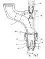
- the in the Fig. 1 and 2 The holding device shown generally corresponds in terms of structure and operation of the holding device 100 of Fig. 5 , The same elements are therefore designated by the same reference numerals. In the following, only the differences are discussed. Furthermore, the joining head 14, on which the holding device 60 of the Fig. 1 and 2 is to be used, the joining head 14 of the Fig. 5 , The general procedure for feeding and providing bolts and the subsequent joining process are otherwise identical, unless otherwise stated.
- the holding device 60 shown is generally constructed like the holding device 100, namely with an insertion section 36 and a clamping section 38.
- the holding device 60 additionally has a securing device 62, which prevents a bolt 26 fed into the holding device 60 from jamming or such Sloping occupies that he can not be raised by the centering 56.
- the securing device 62 can alternatively or additionally prevent a bolt 26 fed into the holding device 60 from falling back against the feed direction (which could be the case, for example, when a bolt 26 is to be mounted against a workpiece 24 against gravity, for example "overhead ").
- the securing device 62 is formed in the interior of the holding device 60.
- the inner diameter of the clamping arms 40 and the Stopparme 44 is greater than a diameter D 1 of the feed channel 22.
- the securing device 62 is formed by a plurality of securing sleeve portions 64 (in the present case two securing sleeve portions 64a, 64b), which together form approximately a sleeve shape define and are arranged concentrically within the insertion section 36.
- the securing sleeve portions 64 each have a peripheral collar portion 66 a, 66 b, which is received in an inner circumferential groove 68 of the housing portion 34.
- the collar portion 66 is movably received within the groove 68.
- the securing sleeve sections 64a, 64b define an inner channel, which in the region of the bearing section 70 has a diameter which corresponds approximately to the diameter D 1 of the feed channel 22.
- the inner channel has a diameter D 2 which is smaller than the diameter D 1 and smaller than that in FIG Fig. 2 shown outer diameter D B of the bolt 26.
- the securing portions 72 of the securing sleeve portions 64 are in particular due to the movable mounting of the collar portion 66 in the radial direction expandable, as shown at 74a and 74b. Accordingly, a supplied via the feed channel 22 bolt with its flange portion 30 are passed through the securing device 62.
- the securing sections 72 widen in the process. Finally, the flange portion 30 reaches a position above the clamping lugs 42 of the clamping arms 40. Once the securing portions 72 back into the in Fig. 1 fall back position shown, the lower ends of the securing portions 72 engage behind the flange portion, as in Fig. 2 is shown.
- the securing device 62 in the present case is formed by two securing sleeve sections 64 in the interior of the holding device 60, it is understood that such a securing device can also be arranged outside the holding device 60 and can protrude into the inner circumference of the holding device 60 at suitable locations, for example via openings in the holding device , It is also generally conceivable that the securing device 62 is formed by elastically deformable means on the inner circumference of the holding device 60. In any case, the securing device 62 is designed to hold the flange section 30 between the clamping section 38 and the securing device 62 in such a manner that the bolt 26 does not assume an excessive inclined position and can not fall back into the feed channel 22.
- the securing sleeve sections 64 may be provided with an outer groove 82.
- elastic pressure means 84 may be arranged, such as an O-ring of a refractory material or a metallic spring ring.
- an O-ring is preferred because it allows a more uniform circumferential force to be exerted on the securing sleeve portions 64.
- Elastic pressure means may for example also be arranged between the groove 68 and the collar portion.
- the shaft portion 28 of the bolt 26 is then gripped by the shaft tensioner 50 and pushed by the cylindrical slotted front portion 41.
- the shaft tensioning device 50 is designed so that its outer diameter is slightly smaller than the outer diameter of the flange portion 30 of the bolt 26.
- the arms 40 are thus expanded and first clamp with their clamping surfaces 43, the flange portion 30 of the bolt 26 so that it can not fall down.
- “below” refers to the in the Fig. 3 illustrated orientation. If the flange portion 30 is pushed through the cylindrical slotted front portion 41, the clamping surfaces 43 snap together and clamp the shaft tensioning device 50 on its outer surface. About the shaft tensioning device 50, the shaft portion 28 of the bolt 26 is then held so that it can not slip down. The bolt 26 is now in the ready position and can be handed over.
- the retainer assembly 39 has a plurality of arms 42, 44 and is longitudinally slotted to provide a degree of elasticity to the arms 42, 44 in the radial direction.
- a support element 90 is guided in the form of a wire according to the invention, wherein in a rest position of the support members 90, a bending portion 92 is located within the collet member 39 and thus reduces a free cross section within the collet member 39.
Landscapes
- Engineering & Computer Science (AREA)
- Mechanical Engineering (AREA)
- Physics & Mathematics (AREA)
- Plasma & Fusion (AREA)
- Fluid Mechanics (AREA)
- Automatic Assembly (AREA)
- Jigs For Machine Tools (AREA)
Priority Applications (1)
| Application Number | Priority Date | Filing Date | Title |
|---|---|---|---|
| PL09776620T PL2321086T3 (pl) | 2008-07-08 | 2009-05-16 | Urządzenie podtrzymujące dla kołków, głowica do spajania i sposób |
Applications Claiming Priority (2)
| Application Number | Priority Date | Filing Date | Title |
|---|---|---|---|
| DE102008033371A DE102008033371A1 (de) | 2008-07-08 | 2008-07-08 | Bolzenhalteeinrichtung |
| PCT/EP2009/003503 WO2010003478A1 (de) | 2008-07-08 | 2009-05-16 | Halteeinrichtung für bolzen, fügekopf und verfahren |
Publications (2)
| Publication Number | Publication Date |
|---|---|
| EP2321086A1 EP2321086A1 (de) | 2011-05-18 |
| EP2321086B1 true EP2321086B1 (de) | 2013-11-20 |
Family
ID=40937534
Family Applications (1)
| Application Number | Title | Priority Date | Filing Date |
|---|---|---|---|
| EP09776620.8A Active EP2321086B1 (de) | 2008-07-08 | 2009-05-16 | Halteeinrichtung für bolzen, fügekopf und verfahren |
Country Status (8)
| Country | Link |
|---|---|
| US (2) | US8533922B2 (pl) |
| EP (1) | EP2321086B1 (pl) |
| CN (1) | CN102149503B (pl) |
| BR (1) | BRPI0915826A2 (pl) |
| DE (1) | DE102008033371A1 (pl) |
| ES (1) | ES2438494T3 (pl) |
| PL (1) | PL2321086T3 (pl) |
| WO (1) | WO2010003478A1 (pl) |
Cited By (2)
| Publication number | Priority date | Publication date | Assignee | Title |
|---|---|---|---|---|
| CN105619158A (zh) * | 2016-03-04 | 2016-06-01 | 宁波夏亿机电科技有限公司 | 用于活塞加工装置的上料机构及活塞加工装置 |
| DE102016115151A1 (de) | 2016-08-16 | 2018-02-22 | Newfrey Llc | Halteeinrichtung für ein Fügeelement, Fügeeinrichtung zum Fügen eines Fügeelementes und Verfahren zum Zuführen eines Fügeelementes |
Families Citing this family (24)
| Publication number | Priority date | Publication date | Assignee | Title |
|---|---|---|---|---|
| DE102009023454A1 (de) * | 2009-06-02 | 2010-12-09 | Newfrey Llc, Newark | Bolzenhalteeinrichtung für Bolzen mit großen Flanschköpfen |
| US9238556B2 (en) | 2011-01-18 | 2016-01-19 | Leoni-Kabel Holding Gmbh | Apparatus for the automated feed of connecting elements to a processing unit and feed hose for the connecting elements |
| DE102011103647A1 (de) | 2011-06-08 | 2012-01-05 | Daimler Ag | Spannzangenwechselvorrichtung, Bolzenschweißanlage und Verfahren zum automatischen Wechseln von Spannzangen |
| CN103447674B (zh) * | 2012-05-31 | 2015-12-16 | 上海赛科利汽车模具技术应用有限公司 | 多规格螺柱的螺柱焊防错装置及方法 |
| EP3052267B1 (en) * | 2013-10-04 | 2023-06-07 | Structural Services, Inc. | Method for automatically welding studs on a surface of a beam |
| DE202013009546U1 (de) | 2013-10-26 | 2015-01-27 | GM Global Technology Operations LLC (n. d. Ges. d. Staates Delaware) | Festlegeeinheit, Befestigungseinrichtung und Kraftfahrzeug |
| EP3037190B1 (en) * | 2014-12-22 | 2020-11-25 | KUKA Systems Aerospace | Gripping device for mechanical fasteners |
| DE102015211818A1 (de) * | 2015-06-25 | 2016-12-29 | Bayerische Motoren Werke Aktiengesellschaft | Verfahren zum Aufschweißen von Verbindungselementen |
| US20170043459A1 (en) * | 2015-08-13 | 2017-02-16 | Raytheon Company | Compliant fastener starter for simultaneous hardware installation |
| JP6697153B2 (ja) * | 2015-09-08 | 2020-05-20 | テイ・エス テック株式会社 | シート |
| JP6649573B2 (ja) * | 2015-09-08 | 2020-02-19 | テイ・エス テック株式会社 | シート |
| DE102016111283A1 (de) * | 2016-06-20 | 2017-12-21 | Newfrey Llc | Ladestift für eine Fügeeinrichtung, Fügeeinrichtung und Fügeelement-Zuführverfahren |
| KR101848620B1 (ko) * | 2016-08-01 | 2018-04-13 | 주식회사 성우하이텍 | 스터드 용접장치 |
| CN107262865B (zh) * | 2017-05-19 | 2019-05-17 | 四川大学 | 一种手持式焊锡装置 |
| EP3437780A1 (en) | 2017-08-03 | 2019-02-06 | Newfrey LLC | Holding device, joining head, joining system and method for feeding studs |
| WO2019118665A1 (en) * | 2017-12-14 | 2019-06-20 | Arconic Inc. | Collet assembly for fastener feeding apparatus |
| DE102018103124A1 (de) * | 2018-02-13 | 2019-08-14 | Böllhoff Verbindungstechnik GmbH | Federarmhülse |
| EP3527318B1 (en) * | 2018-02-16 | 2023-05-17 | Newfrey LLC | Holding device for holding a stud and joining head |
| KR101947563B1 (ko) * | 2018-11-30 | 2019-02-13 | 주식회사 지에스티 | 스터드 용접건 |
| JP7407015B2 (ja) * | 2020-02-19 | 2023-12-28 | ポップリベット・ファスナー株式会社 | 自己穿孔型リベットの締結装置 |
| US12365045B2 (en) | 2020-09-21 | 2025-07-22 | Howmet Aerospace Inc. | Electrodes for resistance welding and method of use thereof |
| CN117733058B (zh) * | 2024-01-26 | 2024-05-28 | 广州德马威工业装备制造有限公司 | 一种spr自冲刺铆接设备送料装置铆钉防翻控制方法 |
| CN118046069B (zh) * | 2024-04-02 | 2025-08-01 | 浙江海默机械工业有限公司 | 一种螺柱用焊枪及其定位方法 |
| CN119841089B (zh) * | 2025-02-20 | 2025-10-10 | 中国兵器装备集团自动化研究所有限公司 | 一种抓取装置 |
Family Cites Families (15)
| Publication number | Priority date | Publication date | Assignee | Title |
|---|---|---|---|---|
| US2735649A (en) * | 1956-02-21 | swallert | ||
| US3698756A (en) * | 1969-12-08 | 1972-10-17 | Combustion Eng | Gripper device having positive engaging and disengaging means |
| DE2447004A1 (de) * | 1974-10-02 | 1976-04-08 | Agfa Gevaert Ag | Spannzange |
| US4183239A (en) * | 1977-09-14 | 1980-01-15 | Potomac Applied Mechanics, Inc. | Two-piece fastener air hammer |
| US4728217A (en) * | 1986-02-26 | 1988-03-01 | Westinghouse Electric Corp. | Gripper apparatus and method |
| ZA871322B (en) * | 1987-02-24 | 1987-10-28 | Alexander Else Frederick | Screw holder |
| US4747997A (en) * | 1987-03-30 | 1988-05-31 | Westinghouse Electric Corp. | Nuclear fuel rod loader for pulling fuel rods into a fuel assembly skeleton |
| US5213311A (en) * | 1992-09-24 | 1993-05-25 | Sabo Ronald J | Nail extractor |
| FR2720963B1 (fr) * | 1994-06-13 | 1996-09-06 | Haute Garonne Ateliers | Dispositif de distribution de pièces à l'unité et dispositif de stockage de ces pièces. |
| US5798494A (en) * | 1996-06-24 | 1998-08-25 | Aoyama; Yoshitaka | Welding apparatus |
| DE29719744U1 (de) * | 1997-11-06 | 1998-02-26 | Emhart Inc., Newark, Del. | Transportvorrichtung für längliche mit einem Kopf und einem Schaft ausgebildete Bauteile |
| US6357110B1 (en) * | 1998-12-31 | 2002-03-19 | Emhart Inc. | Stud electrical connection method |
| US7140087B1 (en) * | 2001-09-06 | 2006-11-28 | Reconnx, Inc. | Methods for extracting fasteners from a host material |
| DE10229690B4 (de) * | 2002-06-26 | 2010-03-25 | Newfrey Llc, Newark | Vorrichtung und Verfahren zum Kurzzeit-Lichtbogenschweißen |
| JP4011524B2 (ja) | 2003-07-09 | 2007-11-21 | ポップリベット・ファスナー株式会社 | スタッド溶接装置 |
-
2008
- 2008-07-08 DE DE102008033371A patent/DE102008033371A1/de not_active Withdrawn
-
2009
- 2009-05-16 BR BRPI0915826A patent/BRPI0915826A2/pt not_active Application Discontinuation
- 2009-05-16 CN CN200980134962.3A patent/CN102149503B/zh active Active
- 2009-05-16 EP EP09776620.8A patent/EP2321086B1/de active Active
- 2009-05-16 WO PCT/EP2009/003503 patent/WO2010003478A1/de not_active Ceased
- 2009-05-16 ES ES09776620.8T patent/ES2438494T3/es active Active
- 2009-05-16 PL PL09776620T patent/PL2321086T3/pl unknown
-
2011
- 2011-01-07 US US12/986,616 patent/US8533922B2/en active Active
-
2013
- 2013-09-16 US US14/027,671 patent/US8793855B2/en active Active
Cited By (3)
| Publication number | Priority date | Publication date | Assignee | Title |
|---|---|---|---|---|
| CN105619158A (zh) * | 2016-03-04 | 2016-06-01 | 宁波夏亿机电科技有限公司 | 用于活塞加工装置的上料机构及活塞加工装置 |
| CN105619158B (zh) * | 2016-03-04 | 2018-03-09 | 宁波夏亿机电科技有限公司 | 用于活塞加工装置的上料机构及活塞加工装置 |
| DE102016115151A1 (de) | 2016-08-16 | 2018-02-22 | Newfrey Llc | Halteeinrichtung für ein Fügeelement, Fügeeinrichtung zum Fügen eines Fügeelementes und Verfahren zum Zuführen eines Fügeelementes |
Also Published As
| Publication number | Publication date |
|---|---|
| WO2010003478A9 (de) | 2010-04-01 |
| WO2010003478A1 (de) | 2010-01-14 |
| CN102149503B (zh) | 2017-02-08 |
| CN102149503A (zh) | 2011-08-10 |
| US8793855B2 (en) | 2014-08-05 |
| DE102008033371A1 (de) | 2010-01-14 |
| PL2321086T3 (pl) | 2014-05-30 |
| US20140079494A1 (en) | 2014-03-20 |
| US8533922B2 (en) | 2013-09-17 |
| BRPI0915826A2 (pt) | 2015-11-03 |
| US20110146456A1 (en) | 2011-06-23 |
| ES2438494T3 (es) | 2014-01-17 |
| EP2321086A1 (de) | 2011-05-18 |
Similar Documents
| Publication | Publication Date | Title |
|---|---|---|
| EP2321086A1 (de) | Halteeinrichtung für bolzen, fügekopf und verfahren | |
| EP2110565B1 (de) | Verbindungsbaugruppe zur Befestigung eines Anbauelements auf einem Trägerelement | |
| DE102009023454A1 (de) | Bolzenhalteeinrichtung für Bolzen mit großen Flanschköpfen | |
| EP2632629B1 (de) | Vorrichtung zur positionierung und zuführung von befestigungselementen | |
| DE102005036808B4 (de) | Druckmittelbetätigte Dockingvorrichtung | |
| EP3983701B1 (de) | Linearantrieb | |
| EP2015047B1 (de) | Verfahren und Vorrichtung zum Zentrieren und Spannen eines Werkstücks in einer Auswuchtmaschine | |
| EP0391262B1 (de) | Spannvorrichtung zum axialen Spannen eines Werkzeugkopfes an einer Werkzeugmaschinenspindel | |
| EP2827006A1 (de) | Blindnietsystem | |
| DE102013012222A1 (de) | Vorrichtung sowie Verfahren zum reversiblen Greifen eines bolzenförmigen Elements, insbesondere eines Nietdorns | |
| EP1738864A2 (de) | Spannvorrichtung | |
| EP2558733B1 (de) | Spreizeinrichtung, verbindung sowie system | |
| EP3165310B1 (de) | Spannvorrichtung | |
| EP1490255B1 (de) | Anordnung mit einem ersten bauteil, einem zweiten bauteil und einem verbindungselement | |
| DE102016111283A1 (de) | Ladestift für eine Fügeeinrichtung, Fügeeinrichtung und Fügeelement-Zuführverfahren | |
| EP2087963A2 (de) | Reibschweißverfahren | |
| WO2015166062A1 (de) | Werkzeughalter | |
| EP3165309B1 (de) | Spannvorrichtung | |
| EP3520965B1 (de) | Spanndorn-anordnung mit niederzugeffekt | |
| EP3302848B1 (de) | Verfahren und fügeelement zum fügen wenigstens zweier bauteile mittels einer fliessformniethülse | |
| DE3233868A1 (de) | Einspanneinrichtung fuer hohle werkstuecke | |
| EP3974660A1 (de) | Selbststanzendes befestigungselement | |
| EP3561358B1 (de) | Verstärkungshülse, schneidringverschraubung und verfahren | |
| DE202018100101U1 (de) | Spanndorn-Anordnung mit Niederzugeffekt | |
| EP0690257A1 (de) | Zugfeste Rohrverbindung und Verfahren zu ihrer Herstellung |
Legal Events
| Date | Code | Title | Description |
|---|---|---|---|
| PUAI | Public reference made under article 153(3) epc to a published international application that has entered the european phase |
Free format text: ORIGINAL CODE: 0009012 |
|
| 17P | Request for examination filed |
Effective date: 20110107 |
|
| AK | Designated contracting states |
Kind code of ref document: A1 Designated state(s): AT BE BG CH CY CZ DE DK EE ES FI FR GB GR HR HU IE IS IT LI LT LU LV MC MK MT NL NO PL PT RO SE SI SK TR |
|
| AX | Request for extension of the european patent |
Extension state: AL BA RS |
|
| DAX | Request for extension of the european patent (deleted) | ||
| 17Q | First examination report despatched |
Effective date: 20111103 |
|
| GRAP | Despatch of communication of intention to grant a patent |
Free format text: ORIGINAL CODE: EPIDOSNIGR1 |
|
| INTG | Intention to grant announced |
Effective date: 20130620 |
|
| GRAS | Grant fee paid |
Free format text: ORIGINAL CODE: EPIDOSNIGR3 |
|
| GRAA | (expected) grant |
Free format text: ORIGINAL CODE: 0009210 |
|
| AK | Designated contracting states |
Kind code of ref document: B1 Designated state(s): AT BE BG CH CY CZ DE DK EE ES FI FR GB GR HR HU IE IS IT LI LT LU LV MC MK MT NL NO PL PT RO SE SI SK TR |
|
| REG | Reference to a national code |
Ref country code: GB Ref legal event code: FG4D Free format text: NOT ENGLISH |
|
| REG | Reference to a national code |
Ref country code: CH Ref legal event code: EP |
|
| REG | Reference to a national code |
Ref country code: AT Ref legal event code: REF Ref document number: 641292 Country of ref document: AT Kind code of ref document: T Effective date: 20131215 |
|
| REG | Reference to a national code |
Ref country code: IE Ref legal event code: FG4D Free format text: LANGUAGE OF EP DOCUMENT: GERMAN |
|
| REG | Reference to a national code |
Ref country code: DE Ref legal event code: R096 Ref document number: 502009008389 Country of ref document: DE Effective date: 20140116 |
|
| REG | Reference to a national code |
Ref country code: ES Ref legal event code: FG2A Ref document number: 2438494 Country of ref document: ES Kind code of ref document: T3 Effective date: 20140117 |
|
| REG | Reference to a national code |
Ref country code: SE Ref legal event code: TRGR |
|
| REG | Reference to a national code |
Ref country code: NL Ref legal event code: VDEP Effective date: 20131120 |
|
| REG | Reference to a national code |
Ref country code: LT Ref legal event code: MG4D |
|
| PG25 | Lapsed in a contracting state [announced via postgrant information from national office to epo] |
Ref country code: NO Free format text: LAPSE BECAUSE OF FAILURE TO SUBMIT A TRANSLATION OF THE DESCRIPTION OR TO PAY THE FEE WITHIN THE PRESCRIBED TIME-LIMIT Effective date: 20140220 Ref country code: IS Free format text: LAPSE BECAUSE OF FAILURE TO SUBMIT A TRANSLATION OF THE DESCRIPTION OR TO PAY THE FEE WITHIN THE PRESCRIBED TIME-LIMIT Effective date: 20140320 Ref country code: LT Free format text: LAPSE BECAUSE OF FAILURE TO SUBMIT A TRANSLATION OF THE DESCRIPTION OR TO PAY THE FEE WITHIN THE PRESCRIBED TIME-LIMIT Effective date: 20131120 Ref country code: FI Free format text: LAPSE BECAUSE OF FAILURE TO SUBMIT A TRANSLATION OF THE DESCRIPTION OR TO PAY THE FEE WITHIN THE PRESCRIBED TIME-LIMIT Effective date: 20131120 Ref country code: NL Free format text: LAPSE BECAUSE OF FAILURE TO SUBMIT A TRANSLATION OF THE DESCRIPTION OR TO PAY THE FEE WITHIN THE PRESCRIBED TIME-LIMIT Effective date: 20131120 Ref country code: HR Free format text: LAPSE BECAUSE OF FAILURE TO SUBMIT A TRANSLATION OF THE DESCRIPTION OR TO PAY THE FEE WITHIN THE PRESCRIBED TIME-LIMIT Effective date: 20131120 |
|
| PG25 | Lapsed in a contracting state [announced via postgrant information from national office to epo] |
Ref country code: LV Free format text: LAPSE BECAUSE OF FAILURE TO SUBMIT A TRANSLATION OF THE DESCRIPTION OR TO PAY THE FEE WITHIN THE PRESCRIBED TIME-LIMIT Effective date: 20131120 |
|
| REG | Reference to a national code |
Ref country code: PL Ref legal event code: T3 |
|
| PG25 | Lapsed in a contracting state [announced via postgrant information from national office to epo] |
Ref country code: PT Free format text: LAPSE BECAUSE OF FAILURE TO SUBMIT A TRANSLATION OF THE DESCRIPTION OR TO PAY THE FEE WITHIN THE PRESCRIBED TIME-LIMIT Effective date: 20140320 |
|
| PG25 | Lapsed in a contracting state [announced via postgrant information from national office to epo] |
Ref country code: EE Free format text: LAPSE BECAUSE OF FAILURE TO SUBMIT A TRANSLATION OF THE DESCRIPTION OR TO PAY THE FEE WITHIN THE PRESCRIBED TIME-LIMIT Effective date: 20131120 |
|
| REG | Reference to a national code |
Ref country code: DE Ref legal event code: R097 Ref document number: 502009008389 Country of ref document: DE |
|
| PG25 | Lapsed in a contracting state [announced via postgrant information from national office to epo] |
Ref country code: CZ Free format text: LAPSE BECAUSE OF FAILURE TO SUBMIT A TRANSLATION OF THE DESCRIPTION OR TO PAY THE FEE WITHIN THE PRESCRIBED TIME-LIMIT Effective date: 20131120 Ref country code: SK Free format text: LAPSE BECAUSE OF FAILURE TO SUBMIT A TRANSLATION OF THE DESCRIPTION OR TO PAY THE FEE WITHIN THE PRESCRIBED TIME-LIMIT Effective date: 20131120 Ref country code: RO Free format text: LAPSE BECAUSE OF FAILURE TO SUBMIT A TRANSLATION OF THE DESCRIPTION OR TO PAY THE FEE WITHIN THE PRESCRIBED TIME-LIMIT Effective date: 20131120 |
|
| PGFP | Annual fee paid to national office [announced via postgrant information from national office to epo] |
Ref country code: IT Payment date: 20140522 Year of fee payment: 6 Ref country code: ES Payment date: 20140526 Year of fee payment: 6 |
|
| PLBE | No opposition filed within time limit |
Free format text: ORIGINAL CODE: 0009261 |
|
| STAA | Information on the status of an ep patent application or granted ep patent |
Free format text: STATUS: NO OPPOSITION FILED WITHIN TIME LIMIT |
|
| PG25 | Lapsed in a contracting state [announced via postgrant information from national office to epo] |
Ref country code: DK Free format text: LAPSE BECAUSE OF FAILURE TO SUBMIT A TRANSLATION OF THE DESCRIPTION OR TO PAY THE FEE WITHIN THE PRESCRIBED TIME-LIMIT Effective date: 20131120 |
|
| 26N | No opposition filed |
Effective date: 20140821 |
|
| REG | Reference to a national code |
Ref country code: DE Ref legal event code: R097 Ref document number: 502009008389 Country of ref document: DE Effective date: 20140821 |
|
| PG25 | Lapsed in a contracting state [announced via postgrant information from national office to epo] |
Ref country code: LU Free format text: LAPSE BECAUSE OF FAILURE TO SUBMIT A TRANSLATION OF THE DESCRIPTION OR TO PAY THE FEE WITHIN THE PRESCRIBED TIME-LIMIT Effective date: 20140516 |
|
| REG | Reference to a national code |
Ref country code: CH Ref legal event code: PL |
|
| PG25 | Lapsed in a contracting state [announced via postgrant information from national office to epo] |
Ref country code: CH Free format text: LAPSE BECAUSE OF NON-PAYMENT OF DUE FEES Effective date: 20140531 Ref country code: MC Free format text: LAPSE BECAUSE OF FAILURE TO SUBMIT A TRANSLATION OF THE DESCRIPTION OR TO PAY THE FEE WITHIN THE PRESCRIBED TIME-LIMIT Effective date: 20131120 Ref country code: LI Free format text: LAPSE BECAUSE OF NON-PAYMENT OF DUE FEES Effective date: 20140531 |
|
| REG | Reference to a national code |
Ref country code: IE Ref legal event code: MM4A |
|
| PG25 | Lapsed in a contracting state [announced via postgrant information from national office to epo] |
Ref country code: SI Free format text: LAPSE BECAUSE OF FAILURE TO SUBMIT A TRANSLATION OF THE DESCRIPTION OR TO PAY THE FEE WITHIN THE PRESCRIBED TIME-LIMIT Effective date: 20131120 |
|
| PG25 | Lapsed in a contracting state [announced via postgrant information from national office to epo] |
Ref country code: IE Free format text: LAPSE BECAUSE OF NON-PAYMENT OF DUE FEES Effective date: 20140516 |
|
| PG25 | Lapsed in a contracting state [announced via postgrant information from national office to epo] |
Ref country code: IT Free format text: LAPSE BECAUSE OF NON-PAYMENT OF DUE FEES Effective date: 20150516 |
|
| PG25 | Lapsed in a contracting state [announced via postgrant information from national office to epo] |
Ref country code: MT Free format text: LAPSE BECAUSE OF FAILURE TO SUBMIT A TRANSLATION OF THE DESCRIPTION OR TO PAY THE FEE WITHIN THE PRESCRIBED TIME-LIMIT Effective date: 20131120 |
|
| REG | Reference to a national code |
Ref country code: FR Ref legal event code: PLFP Year of fee payment: 8 |
|
| PGFP | Annual fee paid to national office [announced via postgrant information from national office to epo] |
Ref country code: PL Payment date: 20160315 Year of fee payment: 8 |
|
| PG25 | Lapsed in a contracting state [announced via postgrant information from national office to epo] |
Ref country code: CY Free format text: LAPSE BECAUSE OF FAILURE TO SUBMIT A TRANSLATION OF THE DESCRIPTION OR TO PAY THE FEE WITHIN THE PRESCRIBED TIME-LIMIT Effective date: 20131120 Ref country code: BG Free format text: LAPSE BECAUSE OF FAILURE TO SUBMIT A TRANSLATION OF THE DESCRIPTION OR TO PAY THE FEE WITHIN THE PRESCRIBED TIME-LIMIT Effective date: 20131120 Ref country code: GR Free format text: LAPSE BECAUSE OF FAILURE TO SUBMIT A TRANSLATION OF THE DESCRIPTION OR TO PAY THE FEE WITHIN THE PRESCRIBED TIME-LIMIT Effective date: 20140221 |
|
| PG25 | Lapsed in a contracting state [announced via postgrant information from national office to epo] |
Ref country code: HU Free format text: LAPSE BECAUSE OF FAILURE TO SUBMIT A TRANSLATION OF THE DESCRIPTION OR TO PAY THE FEE WITHIN THE PRESCRIBED TIME-LIMIT; INVALID AB INITIO Effective date: 20090516 Ref country code: BE Free format text: LAPSE BECAUSE OF FAILURE TO SUBMIT A TRANSLATION OF THE DESCRIPTION OR TO PAY THE FEE WITHIN THE PRESCRIBED TIME-LIMIT Effective date: 20140531 Ref country code: TR Free format text: LAPSE BECAUSE OF FAILURE TO SUBMIT A TRANSLATION OF THE DESCRIPTION OR TO PAY THE FEE WITHIN THE PRESCRIBED TIME-LIMIT Effective date: 20131120 |
|
| REG | Reference to a national code |
Ref country code: FR Ref legal event code: PLFP Year of fee payment: 9 |
|
| PG25 | Lapsed in a contracting state [announced via postgrant information from national office to epo] |
Ref country code: ES Free format text: LAPSE BECAUSE OF NON-PAYMENT OF DUE FEES Effective date: 20150517 |
|
| REG | Reference to a national code |
Ref country code: FR Ref legal event code: PLFP Year of fee payment: 10 |
|
| PG25 | Lapsed in a contracting state [announced via postgrant information from national office to epo] |
Ref country code: MK Free format text: LAPSE BECAUSE OF FAILURE TO SUBMIT A TRANSLATION OF THE DESCRIPTION OR TO PAY THE FEE WITHIN THE PRESCRIBED TIME-LIMIT Effective date: 20131120 |
|
| REG | Reference to a national code |
Ref country code: ES Ref legal event code: FD2A Effective date: 20180704 |
|
| PG25 | Lapsed in a contracting state [announced via postgrant information from national office to epo] |
Ref country code: PL Free format text: LAPSE BECAUSE OF NON-PAYMENT OF DUE FEES Effective date: 20170516 |
|
| PGFP | Annual fee paid to national office [announced via postgrant information from national office to epo] |
Ref country code: GR Payment date: 20190522 Year of fee payment: 15 |
|
| PGFP | Annual fee paid to national office [announced via postgrant information from national office to epo] |
Ref country code: AT Payment date: 20200428 Year of fee payment: 12 |
|
| PG25 | Lapsed in a contracting state [announced via postgrant information from national office to epo] |
Ref country code: SE Free format text: LAPSE BECAUSE OF NON-PAYMENT OF DUE FEES Effective date: 20200517 |
|
| REG | Reference to a national code |
Ref country code: AT Ref legal event code: MM01 Ref document number: 641292 Country of ref document: AT Kind code of ref document: T Effective date: 20210516 |
|
| PG25 | Lapsed in a contracting state [announced via postgrant information from national office to epo] |
Ref country code: AT Free format text: LAPSE BECAUSE OF NON-PAYMENT OF DUE FEES Effective date: 20210516 |
|
| P01 | Opt-out of the competence of the unified patent court (upc) registered |
Effective date: 20230912 |
|
| PGFP | Annual fee paid to national office [announced via postgrant information from national office to epo] |
Ref country code: GB Payment date: 20240522 Year of fee payment: 16 |
|
| PGFP | Annual fee paid to national office [announced via postgrant information from national office to epo] |
Ref country code: FR Payment date: 20240523 Year of fee payment: 16 |
|
| PGFP | Annual fee paid to national office [announced via postgrant information from national office to epo] |
Ref country code: DE Payment date: 20250519 Year of fee payment: 17 |
|
| GBPC | Gb: european patent ceased through non-payment of renewal fee |
Effective date: 20250516 |
|
| PG25 | Lapsed in a contracting state [announced via postgrant information from national office to epo] |
Ref country code: GB Free format text: LAPSE BECAUSE OF NON-PAYMENT OF DUE FEES Effective date: 20250516 |
|
| PG25 | Lapsed in a contracting state [announced via postgrant information from national office to epo] |
Ref country code: FR Free format text: LAPSE BECAUSE OF NON-PAYMENT OF DUE FEES Effective date: 20250531 |