EP2320248B2 - Procédé de détection d'un objet dans un angle mort d'un véhicule et système d'assistance au conducteur pour la détection d'un objet dans un angle mort d'un véhicule - Google Patents
Procédé de détection d'un objet dans un angle mort d'un véhicule et système d'assistance au conducteur pour la détection d'un objet dans un angle mort d'un véhicule Download PDFInfo
- Publication number
- EP2320248B2 EP2320248B2 EP10013904.7A EP10013904A EP2320248B2 EP 2320248 B2 EP2320248 B2 EP 2320248B2 EP 10013904 A EP10013904 A EP 10013904A EP 2320248 B2 EP2320248 B2 EP 2320248B2
- Authority
- EP
- European Patent Office
- Prior art keywords
- group
- detection signals
- vehicle
- horizontal angle
- angle width
- Prior art date
- Legal status (The legal status is an assumption and is not a legal conclusion. Google has not performed a legal analysis and makes no representation as to the accuracy of the status listed.)
- Active
Links
- 238000000034 method Methods 0.000 title claims description 16
- 238000001514 detection method Methods 0.000 claims description 159
- 238000011156 evaluation Methods 0.000 claims description 3
- 230000005540 biological transmission Effects 0.000 description 13
- 238000013461 design Methods 0.000 description 4
- 238000010586 diagram Methods 0.000 description 4
- 238000005259 measurement Methods 0.000 description 2
- 230000015572 biosynthetic process Effects 0.000 description 1
- 230000001419 dependent effect Effects 0.000 description 1
- 230000007274 generation of a signal involved in cell-cell signaling Effects 0.000 description 1
- 238000002955 isolation Methods 0.000 description 1
- 238000012544 monitoring process Methods 0.000 description 1
- 230000003287 optical effect Effects 0.000 description 1
- 238000012545 processing Methods 0.000 description 1
- 230000035484 reaction time Effects 0.000 description 1
- 230000008054 signal transmission Effects 0.000 description 1
- 238000012546 transfer Methods 0.000 description 1
Images

Classifications
-
- G—PHYSICS
- G01—MEASURING; TESTING
- G01S—RADIO DIRECTION-FINDING; RADIO NAVIGATION; DETERMINING DISTANCE OR VELOCITY BY USE OF RADIO WAVES; LOCATING OR PRESENCE-DETECTING BY USE OF THE REFLECTION OR RERADIATION OF RADIO WAVES; ANALOGOUS ARRANGEMENTS USING OTHER WAVES
- G01S17/00—Systems using the reflection or reradiation of electromagnetic waves other than radio waves, e.g. lidar systems
- G01S17/87—Combinations of systems using electromagnetic waves other than radio waves
-
- G—PHYSICS
- G01—MEASURING; TESTING
- G01S—RADIO DIRECTION-FINDING; RADIO NAVIGATION; DETERMINING DISTANCE OR VELOCITY BY USE OF RADIO WAVES; LOCATING OR PRESENCE-DETECTING BY USE OF THE REFLECTION OR RERADIATION OF RADIO WAVES; ANALOGOUS ARRANGEMENTS USING OTHER WAVES
- G01S17/00—Systems using the reflection or reradiation of electromagnetic waves other than radio waves, e.g. lidar systems
- G01S17/88—Lidar systems specially adapted for specific applications
- G01S17/93—Lidar systems specially adapted for specific applications for anti-collision purposes
- G01S17/931—Lidar systems specially adapted for specific applications for anti-collision purposes of land vehicles
-
- G—PHYSICS
- G01—MEASURING; TESTING
- G01S—RADIO DIRECTION-FINDING; RADIO NAVIGATION; DETERMINING DISTANCE OR VELOCITY BY USE OF RADIO WAVES; LOCATING OR PRESENCE-DETECTING BY USE OF THE REFLECTION OR RERADIATION OF RADIO WAVES; ANALOGOUS ARRANGEMENTS USING OTHER WAVES
- G01S17/00—Systems using the reflection or reradiation of electromagnetic waves other than radio waves, e.g. lidar systems
- G01S17/02—Systems using the reflection of electromagnetic waves other than radio waves
- G01S17/06—Systems determining position data of a target
- G01S17/42—Simultaneous measurement of distance and other co-ordinates
-
- G—PHYSICS
- G01—MEASURING; TESTING
- G01S—RADIO DIRECTION-FINDING; RADIO NAVIGATION; DETERMINING DISTANCE OR VELOCITY BY USE OF RADIO WAVES; LOCATING OR PRESENCE-DETECTING BY USE OF THE REFLECTION OR RERADIATION OF RADIO WAVES; ANALOGOUS ARRANGEMENTS USING OTHER WAVES
- G01S13/00—Systems using the reflection or reradiation of radio waves, e.g. radar systems; Analogous systems using reflection or reradiation of waves whose nature or wavelength is irrelevant or unspecified
- G01S13/88—Radar or analogous systems specially adapted for specific applications
- G01S13/93—Radar or analogous systems specially adapted for specific applications for anti-collision purposes
- G01S13/931—Radar or analogous systems specially adapted for specific applications for anti-collision purposes of land vehicles
- G01S2013/9315—Monitoring blind spots
Definitions
- the invention relates to a method for detecting an object in a blind spot area of a vehicle, in which a plurality of detection signals of a signal packet are emitted by a sensor unit and evaluated on the object and received by a receiving unit signals. Furthermore, the invention relates to a driver assistance system for detecting an object in a blind spot area of a vehicle.
- Fig. 1 a vehicle 1, which has a longitudinal axis A.
- the vehicle 1 comprises a driver assistance system 2, which has a sensor device 3.
- the sensor unit 3 is designed as a sensor array and comprises a plurality of individual infrared sensors.
- the sensor unit 3 is formed on the vehicle in such a way that it is designed to detect objects in a blind spot area 4 formed to the right of the vehicle.
- the surface area of the blind spot area 4 shown by way of example and schematically is covered by the infrared signals of the individual sensors of the sensor unit 3.
- the individual sensors of the sensor unit 3 generate all sensor signals which have a same horizontal angular width b.
- the signals of the individual sensors are designed differently with regard to their emission angle between the main axis of the signal and the vehicle longitudinal axis A. By means of these different emission directions of the signals of the individual sensors, a corresponding surface area to be monitored is covered laterally and behind the vehicle. Due to this configuration of the sensor unit, in which all sensors emit signals 5 to 20 with the same horizontal angular width, however, the problem arises that on the one hand at relatively far front and far to the side of the vehicle 1 objects located in the blind spot area, a relatively high number of signals reflected on the object and received by the sensor unit 3 occurs, whereby the amount of data to be processed is very large.
- the WO 2006/035019 A1 discloses an infrared sensor for parking space measurement having at least two detection areas.
- the patent US 6,363,326 B1 shows a method and apparatus for blind spot monitoring for motor vehicles.
- This device has a plurality of sensors.
- a laser beam device for motor vehicles which divides an area lying in front of the motor vehicle into a plurality of examination areas.
- a blind spot sensor system for detecting and / or classifying objects in a defined surveillance area of a motor vehicle by means of radar technology, comprising at least a first means for emitting a first radar beam and a second means for emitting a second radar beam.
- a plurality of detection signals of a signal packet are emitted with a sensor unit and signals reflected at the object and received by a receiving unit are evaluated. At least two detection signals are sent out with different horizontal angles. This means that a first detection signal having a first horizontal angular width is emitted and at least one second detection signal is emitted with a different horizontal angle width than the first horizontal angle width.
- a first group of detection signals having a first horizontal angular width and a second group of detection signals having a second horizontal angular width different from the first are emitted.
- Such group formation ensures that, according to the invention, a plurality of detection signals are emitted for each group, thereby also improving the accuracy and precision of the object detection.
- each group comprises at least two detection signals which are transmitted and the detection signals of a group with the same horizontal angular width are transmitted.
- a transmission of a plurality of detection signals is carried out within the group, all of which are generated with the same angular width in the horizontal direction.
- the sensor unit has a plurality of stationary individual sensors arranged directly next to one another. These can emit their detection signals simultaneously or in chronological succession. If they are transmitted one after the other, it is preferably provided that this takes place at a frequency between 12 Hz and 100 Hz.
- a signal packet includes all detection signals of the sensor unit emitted simultaneously or in succession, each time for a single transmission.
- the sensor unit has more than 5, in particular more than 10, in particular 16 sensors. These each generate a detection signal during a measurement cycle, such that a signal packet of 16 detection signals results in such an embodiment. In a subsequent second signal packet, in turn, in each case a detection signal of each sensor is transmitted, etc.
- the transmission of the transmission signal begins with the sensor which emits the transmission signal with the smallest angle with respect to the longitudinal axis of the vehicle.
- the group of detection signals which have the smallest horizontal angular widths is first emitted.
- the detection signal of the second group is transmitted with an at least 50 percent, in particular at least 90 percent, preferably between 95 and 105 percent, in particular 100 percent, greater horizontal angle width than the detection signal of the first group.
- the horizontal angular widths are emitted by a substantially different width value. This takes particular account of the aforementioned advantages.
- a detection signal of the first group with a horizontal angular width between 1 ° and 2 °, in particular between 1 ° and 1.5 ° is emitted.
- Particularly advantageous in this context is a horizontal angular width of 1.25 °.
- a third group of detection signals with a horizontal angular width greater than the first and greater of the second group is transmitted.
- the object recognition can be further improved.
- Such a widening of the horizontal angular width in the third group of detection signals is particularly advantageous in view of the relatively lateral emission of these detection signals, so that these detection signals are preferably emitted at a relatively large angle with respect to their main emission axis to the vehicle longitudinal axis.
- the number of reflected signals which are then also received can be reduced, so that the objects of information obtained from received signals received in objects in these local areas of the blind spot area can be reduced, but the probability of object recognition is still not affected.
- the third group is emitted simultaneously with the first and / or the second group depending on the design of the sensor unit. It can also be provided that the detection signals of the third group differ laterally to which the first and / or the second group are sent. In particular, it is then preferably provided in the case of such a time-offset transmission that the third group is transmitted in time after the first and after the second group. Again, in this regard, a clock frequency between 12 Hz and 100 Hz may be preferably provided for the entire signal packet.
- a detection signal of the third group is transmitted with a horizontal angle width which is larger by at least 300 percent, in particular between 350 percent and 400 percent, than the angular width of the first group. Also in this regard, a larger by far greater horizontal angle width is provided, which is significantly reduced with respect to the object detection in conjunction with a data reduction, which is to be evaluated with respect to the object recognition.
- a number greater than 1 of detection signals in particular four detection signals is also emitted by the third group. It is particularly advantageous if the number of detection signals of the third group is set smaller than the number of detection signals of the first and / or less than the number of the second group. In particular, it is provided that in each case an equal number greater than 1, in particular 6, of detection signals is emitted by the first and the second group. Especially such a division of detection signals, in particular in conjunction with the specific angular widths offers a particularly optimized design with regard to a precise object detection in all areas of the blind spot area, wherein moreover the object detection is generated with area-dependent adapted and most suitable amounts of data.
- a detection signal having a smaller horizontal angular width is transmitted at a smaller angle to the vehicle longitudinal axis than a detection signal having a larger horizontal angular width.
- the horizontal angular width of the transmission signals increases with increasing angle between the vehicle longitudinal axis and the main axis of a horizontal angular range of a transmission signal.
- the detection signals of the first group with respect to their angular orientation to the vehicle longitudinal axis are oriented closer thereto than the detection signals of the second group and the third group.
- this system has at least one sensor unit which is designed to generate a plurality of detection signals of a signal packet.
- the driver assistance system also includes a receiving unit, which is designed to evaluate received signals reflected at the object. At least two emitted detection signals have different horizontal angular widths as compared with each other.
- a detection signal having a smaller horizontal angular width is emitted at a smaller distance angle in the vehicle longitudinal axis than a detection signal having a larger horizontal angular width.
- a first group of detection signals having a first horizontal angular width and a second group of detection signals having a second horizontal angular width different from the first are emitted.
- Each group comprises at least two detection signals and the detection signals of a group are transmitted with the same horizontal angular width.
- Fig. 2 is shown in a schematic plan view of a vehicle 21, which is a passenger car.
- the vehicle 21 moves in accordance with the arrow P1.
- the vehicle 21 comprises a driver assistance system 22, which is designed to detect objects in a blind spot area 25 of the vehicle 21.
- the driver assistance system 22 has a first sensor unit 23, which is arranged on the right side of the vehicle 21 and which is designed to detect a blind spot area 25.
- a further sensor unit 26 is also arranged, which is designed for detecting objects in a blind spot area, not shown, on the left side of the vehicle 21.
- driver assistance system 22 includes a control and evaluation unit 24, which is designed to evaluate the signals detected by the sensor units 23 and 26.
- the sensor unit 23 is a sensor array having a plurality of individual infrared sensors. In the exemplary embodiment, it is provided that 16 separate infrared sensors are provided in this regard, the number in this regard being exemplary. Each of these individual sensors of the sensor unit 23 is designed to generate an infrared signal as a detection signal. For this purpose, it is provided that sensors of the sensor unit 23 emit detection signals of a first group 27. In the embodiment, six sensors are provided in this regard, each emitting a detection signal 28, 29, 30, 31, 32 and 33. These detection signals 28 to 33 are the detection signals which are emitted to the rear, as it were, to the rear of the vehicle 21. This means that they are sent as close to the vehicle as possible and far to the rear.
- these detection signals 28 to 33 of the first group 27 are oriented with smaller angles of their main emission direction to the axis A 'of the vehicle longitudinal axis A shifted towards the vehicle edge.
- the angle ⁇ is indicated, which designates the angle between the axis A 'and the main direction of the detection signal 28.
- a second group 34 of detection signals is emitted by further sensors of the sensor unit 23.
- detection signals 35, 36, 37, 38, 39 and 40 are likewise transmitted by six sensors in this respect.
- the individual detection signals 35 to 40 of the second group 34 each have larger angles to the axis A 'than the detection signals 28 to 33 of the first group 27.
- the angle ⁇ is plotted, which is the angle between the axis A' and the main direction of the detection signal 35, and which is greater than the angle ⁇ and the non-illustrated respective angles between the detection signals 29 to 33 and the axis A1 '.
- a third group 41 is sent out by detection signals.
- the third group 41 in the exemplary embodiment comprises four detection signals 42, 43, 44 and 45.
- the number of detection signals 42 to 45 of the third group 41 is therefore less than the number of detection signals 28 to 33 of the first group 27 and also of the detection signals 35 to 40
- the second group 34 is shown by way of example.
- the angle ⁇ denotes the angle between the axis A 'and the main direction of the detection signal 42.
- the angle ⁇ is greater than the angles ⁇ and ⁇ .
- the detection signals of all three groups 27, 34 and 41 are constructed so as to be side by side with respect to their emission direction or fan-shaped so that they cover a total range of about 40 ° with respect to the angular expansion.
- the four detection signals 42 to 45 of the third group 41 are emitted with larger angles of their main emission to the axis A 'as the detection signals of the first group 27 and the second group 34. Based on the detection signals 28 to 33 of the first group 27, the detection signals 35 to 40 of the second group 34 thus further laterally outwardly with respect to the vehicle 21 obliquely emitted to the rear. On the other hand, the detection signals 42 to 45 of the third group 41 are further emitted laterally obliquely outward with respect to the vehicle 21 in comparison with the detection signals of the first group 27 and the second group 34.
- the horizontal angular widths b1 of the detection signals of the first group 27 are different from the horizontal angle width b2 of the detection signals of the second group 34 and also different from the horizontal angle width b3 of the detection signals of the third group 41.
- the detection signals 28 to 33 of the first group 27 all have a same horizontal angular width b1.
- a horizontal angle width is to be understood as representing the angle between the two signal limits of a detection signal 28 to 33.
- the signal lobe width is to be understood, which forms in the plane of the figure and thus in the x, y plane.
- this horizontal angular width b1 is 1.25 °.
- the detection signals 35 to 40 of the second group 34 are generated with a larger compared to the horizontal angular width b1 horizontal angular width b2. Again, all the detection signals 35 to 40 of the second group 34 are radiated with this horizontal angular width b2. In the exemplary embodiment, this horizontal angular width b2 is 2.5 °.
- the detection signals 42 to 45 of the third group 41 are generated with a third horizontal angular width b3. Again, all the detection signals 42 to 45 are generated with this same horizontal angular width b3.
- the horizontal angular width b3 is 4.4 ° in the embodiment.
- the horizontal angular widths b1, b2, b3 are all different from the horizontal angular width b in the prior art, which is 3 °.
- the sensor unit 26 is formed on the left side of the vehicle 21. It can be provided that the detection signals of the three groups 27, 34 and 41 are emitted substantially simultaneously. However, it can also be provided that the sensor unit 23 is designed in this way; in that the detection signals of the first group 27 are emitted, for example, in time before the detection signals of the second group 34 and before the third groups 41. In this regard, it can then also be provided that the detection signals 28 to 33 of the first group 27 are transmitted simultaneously.
- detection signals 28 to 33 of the first group 27 are emitted ahead of those of the group 34 and the group 41, these detection signals 28 to 33 will also be transmitted one after the other, preferably then the first detection signal 28 and in further chronological order then the detection signals 29 to 33 are transmitted following.
- the respective sensors can be equipped correspondingly by individual optical elements in front of a photodiode in order to be able to achieve the relevant orientation and emission characteristic.
- each of the sensors of the sensor unit 23 preferably comprises a receiving unit, by means of which the transmission signals reflected at the detection range of the detected objects are received.
- Fig. 2 shown opposing sensor units 23 and 26, these may be identical. In order to be able to ensure the corresponding signal generation and fanning in the corresponding angular widths, it can then be provided that the sensor unit 26 is arranged in an inverted arrangement on the left side of the vehicle 21.
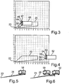
- Fig. 3 a schematic diagram is shown in which the sensor unit 23 is arranged at zero point.
- the horizontal axis indicates the distance to the rear, wherein the vertical axis represents the distance laterally to this sensor unit 23.
- the object 46 which represents a vehicle
- the number of received signals 47 to 51 is merely exemplary, but is reduced in comparison to the prior art in which, as shown in FIG Fig. 1 and transfer the situation in Fig. 3 on this system in Fig. 1 a significantly higher number of received signals would occur. This is the amount of data that is in Fig. 1 must be evaluated, much higher and the statement precision just at these specific positions relatively far laterally and relatively far forward with respect to the vehicle 21 is not improved.
- This embodiment is particularly advantageous with the corresponding number of detection signals whose orientation and a blind spot area 25 customary for a passenger vehicle according to the vehicle 21 ensure the best possible detection of further corresponding vehicles.
- This with regard to the usual widths in the range of 2 m of vehicles to be detected as objects in this respect also have corresponding blind spot areas, as shown in the figures.
- Fig. 4 a further diagram is shown, in which also the sensor unit 23 is arranged at zero point.
- the blind spot area 25 is analogous to the representation in FIG Fig. 3 ,
- an object 53 is still relatively far behind the vehicle 21 and thus also far behind the sensor unit 23, in which respect a distance of 14 m is formed.
- the sensors of the sensor unit 23 also generate detection signals 28 to 33, thus also detection signals 35 to 40 as well as detection signals 42 to 45, which extend beyond the blind spot area 25 and can detect correspondingly.
- objects 52 as they are in Fig. 4 are shown, which are arranged relatively far behind the vehicle 21 but relatively close to the vehicle longitudinal axis A, advantageous.
- a detection of the object 52 is therefore already possible when it is outside the blind spot area 25. This is also necessary for the reason that, with respect to the signal transmission, the signal propagation time, the received signals and the related evaluation, a time period passes during which the object 52 enters the blind spot area 25. This means that due to these circumstances, such an early detection is required in order to be able to make a corresponding statement in this regard when the object 52 actually enters the blind spot area 25.
- this specific horizontal angular widths b1, b2, b3 this is advantageous in that at usual vehicle widths already about 1.8 m from objects to be detected at a distance of about 15 m to the sensor unit 23 are detected accordingly.
- the detection signals 28 to 33 with their exemplary horizontal angular width b1 at a distance of 15 m to a horizontal signal width of 0.32 m. This can, as well as in Fig. 4 is shown, five detection signals detect the object 52 and corresponding reflected signals 53 to 57 are then received again.
- the reflected signals 53, 54, 55, 56 and 57 are shown.
- relative speeds between the object 52 and the vehicle 21 of 50 km / h are considered, with a reaction time of the driver assistance system 22 with respect to the transmission of the detection signals, their reception and processing 300 exemplified ms is.
- the illustration in FIG Fig. 4 it is therefore necessary to detect already 4.2 m after the end (at 10 m) of the blind spot area 25.
- a different design and termination is possible in this respect.
- Fig. 5 is shown in a further exemplary representation of the detection signal 28 which strikes an object 58 side.
- This narrow horizontal cross-section of the detection signal 28 creates a more accurate lateral detection of the object 58. Inaccuracies due to a too wide and possibly over the length of the object 58 protruding forward and backward detection signal 28 can be prevented, so that in this regard inaccuracies in the object detection can be avoided in comparison to the prior art.
- the detection signal 28 which can detect relatively accurately one of two relatively close to each other moving objects due to its small horizontal angular width. Due to the very narrow horizontal widening of the detection signal 28, it can be precisely determined in comparison with the prior art that the reflection from the object 60, which represents a vehicle, does not occur on the front object 50. In an embodiment according to Fig. 1 Such a detection would not be possible in the prior art because, due to the large horizontal width of the detection signals 5 close to the vehicle, the signal would impinge on the object 59 and the object 60 and a single long object would be detected in this respect.
Landscapes
- Physics & Mathematics (AREA)
- Engineering & Computer Science (AREA)
- Electromagnetism (AREA)
- Computer Networks & Wireless Communication (AREA)
- General Physics & Mathematics (AREA)
- Radar, Positioning & Navigation (AREA)
- Remote Sensing (AREA)
- Traffic Control Systems (AREA)
Claims (9)
- Procédé de détection d'un objet (46, 52, 58 à 60) dans une zone d'angle mort (25) d'un véhicule (21), dans lequel une pluralité de signaux de détection (28 à 45) d'un paquet de signaux peut être envoyée au moyen d'une unité de détection (23, 26) et dans lequel le cas échéant, les signaux réfléchis au niveau de l'objet (46, 52, 58 à 60) et reçus par l'unité de détection (23, 26) sont analysés ;
un premier groupe (27) de signaux de détection (28 à 33) étant envoyé avec une première largeur d'angle horizontale (b1) et un deuxième groupe (34) de signaux de détection (35 à 40) étant envoyé avec une deuxième largeur d'angle horizontale (b2) différente de la première ;
le premier groupe (27) de signaux de détection (28 à 33) étant envoyé avec une plus petite largeur d'angle horizontale (b1) dans un plus petit angle (α) par rapport à l'axe longitudinal du véhicule (A, A') que le deuxième groupe (34) de signaux de détection (35 à 40) avec une plus grande largeur d'angle horizontale (b2), la plus grande largeur d'angle horizontale (b2) étant supérieure à ladite plus petite largeur d'angle horizontale (b1), chacun des groupes (27, 34) comprenant au moins deux signaux de détection (28 à 40) et les signaux de détection (28 à 40) d'un groupe (27, 34) étant envoyés avec la même largeur d'angle horizontale (b1, b2),
caractérisé en ce que
les signaux de détection (28 à 40) d'un groupe (27, 34) ont des angles différents (α) par rapport à l'axe longitudinal du véhicule (A, A'). - Procédé selon la revendication 1, caractérisé en ce que le signal de détection (35 à 40) du deuxième groupe (34) est envoyé avec une plus grande largeur d'angle horizontale (b2), d'au moins 50 %, notamment d'au moins 90 %, de préférence entre 95 % et 105 %, que le signal de détection (28 à 33) du premier groupe (27) .
- Procédé selon la revendication 1 ou 2, caractérisé en ce qu'un signal de détection (28 à 33) du premier groupe (27) est envoyé avec une largeur d'angle horizontale (b1) comprise entre 1° et 2°, notamment entre 1° et 1,5°.
- Procédé selon l'une quelconque des revendications 1 à 3, caractérisé en ce qu'un troisième groupe (41) de signaux de détection (42 à 45) est envoyé à une largeur d'angle horizontale (b3) supérieure à la largeur d'angle horizontale du premier groupe (27) et supérieure à la largeur d'angle horizontale (b2) du deuxième groupe (34).
- Procédé selon la revendication 4, caractérisé en ce que le troisième groupe (41) est envoyé un certain temps après le premier (27) et le deuxième groupe (34) ou simultanément au premier (27) et/ou au deuxième groupe (34).
- Procédé selon la revendication 4 ou 5, caractérisé en ce qu'un signal de détection (42 à 45) du troisième groupe (41) est envoyé avec une largeur d'angle horizontale (b3) supérieure d'au moins 300 %, notamment entre 350 % et 400 %, que la largeur d'angle horizontale du premier groupe (27).
- Procédé selon l'une quelconque des revendications 4 à 6, caractérisé en ce qu'un nombre supérieur à 1 de signaux de détection (42 à 45), notamment 4, et inférieur au nombre du premier (27) et/ou du deuxième groupe (34) est envoyé par le troisième groupe (41).
- Procédé selon l'une quelconque des revendications 1 à 7, caractérisé en ce que respectivement un nombre égal, supérieur à 1, notamment de 6, de signaux de détection (28 à 40) est envoyé par le premier (27) et le deuxième groupe (34).
- Système d'assistance au conducteur servant à la détection d'un objet (46, 52, 58 à 60) dans une zone d'angle mort (25) d'un véhicule (21) comportant une unité de détection (23, 26) réalisée pour produire une pluralité de signaux de détection (28 à 45) d'un paquet de signaux et comportant une unité d'analyse (24) réalisée pour analyser les signaux reçus réfléchis au niveau de l'objet (46, 52, 58 à 60) ;
un premier groupe (27) de signaux de détection (28 à 33) étant envoyé avec une première largeur d'angle horizontale et un deuxième groupe (34) de signaux de détection (35 à 40) étant envoyé avec une deuxième largeur d'angle horizontale (b2) différente de la première ;
le premier groupe (27) de signaux de détection (28 à 33) étant envoyé avec une plus petite largeur d'angle horizontale dans un plus petit angle (α) par rapport à l'axe longitudinal du véhicule (A, A') que le deuxième groupe (34) de signaux de détection (35 à 40) avec une plus grande largeur d'angle horizontale (b2), la plus grande largeur d'angle horizontale (b2) étant supérieure à ladite plus petite largeur d'angle horizontale (b1), chacun des groupes (27, 34) comprenant au moins deux signaux de détection (28 à 40) et les signaux de détection (28 à 40) d'un groupe (27, 34) étant envoyés avec la même largeur d'angle horizontale (b1, b2),
caractérisé en ce que
les signaux de détection (28 à 45) d'un groupe (27, 34) ont des angles différents (α) par rapport à l'axe longitudinal du véhicule (A, A').
Applications Claiming Priority (1)
| Application Number | Priority Date | Filing Date | Title |
|---|---|---|---|
| DE102009052591A DE102009052591A1 (de) | 2009-11-10 | 2009-11-10 | Verfahren zum Erfassen eines Objekts in einem Totwinkelbereich eines Fahrzeugs und Fahrassistenzsystem zur Erfassung eines Objekts in einem Totwinkelbereich eines Fahrzeugs |
Publications (4)
| Publication Number | Publication Date |
|---|---|
| EP2320248A2 EP2320248A2 (fr) | 2011-05-11 |
| EP2320248A3 EP2320248A3 (fr) | 2011-11-16 |
| EP2320248B1 EP2320248B1 (fr) | 2016-01-13 |
| EP2320248B2 true EP2320248B2 (fr) | 2019-01-02 |
Family
ID=43558392
Family Applications (1)
| Application Number | Title | Priority Date | Filing Date |
|---|---|---|---|
| EP10013904.7A Active EP2320248B2 (fr) | 2009-11-10 | 2010-10-23 | Procédé de détection d'un objet dans un angle mort d'un véhicule et système d'assistance au conducteur pour la détection d'un objet dans un angle mort d'un véhicule |
Country Status (2)
| Country | Link |
|---|---|
| EP (1) | EP2320248B2 (fr) |
| DE (1) | DE102009052591A1 (fr) |
Families Citing this family (1)
| Publication number | Priority date | Publication date | Assignee | Title |
|---|---|---|---|---|
| DE102020109882A1 (de) | 2020-04-08 | 2021-10-14 | Stefan Sels | Sensorvorrichtung zum Überwachen des Totwinkelbereichs eines Fahrzeugs |
Family Cites Families (11)
| Publication number | Priority date | Publication date | Assignee | Title |
|---|---|---|---|---|
| DE3244358C2 (de) * | 1982-12-01 | 1984-10-04 | Daimler-Benz Ag, 7000 Stuttgart | Einrichtung zur Erfassung von Hindernissen als Rangierhilfe beim Einparken oder Wenden eines Kraftfahrzeuges |
| DE3635396A1 (de) * | 1986-10-17 | 1988-04-28 | Bayerische Motoren Werke Ag | Vorrichtung zum erkennen von hindernissen fuer kraftfahrzeuge |
| DE4343092A1 (de) * | 1993-12-17 | 1995-06-22 | Bayerische Motoren Werke Ag | Laserstrahleinrichtung für Kraftfahrzeuge |
| US6363326B1 (en) * | 1997-11-05 | 2002-03-26 | Robert Lawrence Scully | Method and apparatus for detecting an object on a side of or backwards of a vehicle |
| DE19904043A1 (de) * | 1999-02-02 | 2000-08-03 | Valeo Schalter & Sensoren Gmbh | System und Verfahren zum Überwachen eines Bereichs an der Seite eines Fahrzeugs |
| DE19927395A1 (de) | 1999-06-16 | 2001-01-04 | Daimler Chrysler Ag | Vorrichtung und Verfahren zur Erhöhung der Winkelauflösung einer Antennenanordnung |
| US6452534B1 (en) * | 2000-08-04 | 2002-09-17 | Visteon Global Technologies, Inc. | Radar field-of-view enhancement method and apparatus for matching field-of-view to desired detection zone |
| DE10303578B4 (de) * | 2003-01-30 | 2015-08-13 | SMR Patents S.à.r.l. | Gefahrenerkennungssystem für Fahrzeuge mit mindestens einer seitlichen und rückwärtigen Umgebungserfassung |
| DE102004019651A1 (de) | 2004-04-22 | 2005-11-17 | Siemens Ag | Blindspot-Sensorsystem |
| DE102005046000A1 (de) * | 2004-09-28 | 2006-05-04 | Continental Teves Ag & Co. Ohg | Vorrichtung zum Erfassen eines seitlichen Umfelds eines Fahrzeugs |
| JP4098318B2 (ja) * | 2005-03-29 | 2008-06-11 | 本田技研工業株式会社 | 電子走査型ミリ波レーダ装置およびコンピュータプログラム |
-
2009
- 2009-11-10 DE DE102009052591A patent/DE102009052591A1/de not_active Withdrawn
-
2010
- 2010-10-23 EP EP10013904.7A patent/EP2320248B2/fr active Active
Also Published As
| Publication number | Publication date |
|---|---|
| EP2320248B1 (fr) | 2016-01-13 |
| EP2320248A3 (fr) | 2011-11-16 |
| DE102009052591A1 (de) | 2011-05-12 |
| EP2320248A2 (fr) | 2011-05-11 |
Similar Documents
| Publication | Publication Date | Title |
|---|---|---|
| EP1910866B1 (fr) | Procede pour determiner une limitation en profondeur d'un creneau de stationnement au moyen de capteurs a ultrasons et systeme associe | |
| EP1664838B1 (fr) | Procede et programme informatique pour detecter le contour d'un obstacle dans l'environnement d'un vehicule | |
| DE102013008953B4 (de) | Verfahren zum Betreiben einer Radareinrichtung eines Fahrzeugs, insbesondere eines Kraftwagens, sowie Radareinrichtung für ein Fahrzeug, insbesondere einen Kraftwagen | |
| DE102012021973A1 (de) | Verfahren zum Betreiben eines Radarsensors eines Kraftfahrzeugs, Fahrerassistenzeinrichtung und Kraftfahrzeug | |
| DE102013218571A1 (de) | Vorrichtung und Verfahren zur seitlichen Umfelderfassung eines Kraftfahrzeugs | |
| EP2084554A1 (fr) | Système radar pour véhicules automobiles | |
| DE102011012379A1 (de) | Verfahren und Radar-Sensoranordnung zur Detektion von Ort und Geschwindigkeit von Objekten relativ zu einem Fahrzeug | |
| EP1801613B1 (fr) | Procédé et dispositif destinés à la détection d'objets dans l'environnement d'un véhicule | |
| DE102010024328B4 (de) | Radarvorrichtung mit situationsadaptiver Modulationsumschaltung und Steuerungsverfahren | |
| WO2019038174A1 (fr) | Évitement d'avertissements d'angle mort dûs à des éclaboussures | |
| EP2895880B1 (fr) | Procédé de surveillance fonctionnelle de capteurs à ultrasons | |
| WO2015193060A1 (fr) | Procédé permettant de supprimer les signaux d'écho d'un système de remorque sur un véhicule automobile, dispositif d'aide à la conduite et véhicule automobile | |
| EP3602119B1 (fr) | Procédé de détection d'un objet dans une zone environnante d'un véhicule à moteur avec classification de l'objet, dispositif de capteur ultrasonique et véhicule à moteur | |
| DE102010021053B3 (de) | Verfahren zur Detektion von Störungen des Messbetriebs einer Ultraschall-Messanordnung eines Kraftfahrzeugs und Kraftfahrzeug | |
| EP1762861B1 (fr) | Procédé et dispositif de mesure de créneaux de stationnement d'un vehicule automobile | |
| EP2320248B2 (fr) | Procédé de détection d'un objet dans un angle mort d'un véhicule et système d'assistance au conducteur pour la détection d'un objet dans un angle mort d'un véhicule | |
| WO2004059341A1 (fr) | Procede permettant d'acquerir des informations relatives a un environnement et procede permettant de determiner la position d'une place de stationnement | |
| EP2607919A1 (fr) | Procédé de détection sans contact d'un objet dans un environnement d'un véhicule, dispositif d'assistance du conducteur avec dispositif de capteur à ultrasons et véhicule équipé d'un tel dispositif d'assistance du conducteur | |
| DE102017115457A1 (de) | Erkennung einer Fehlstellung eines Abstandssensors basierend auf einem Verhältnis von Detektionsmerkmalen | |
| EP3018490B1 (fr) | Procede de detection d'une interference dans un signal de reception d'un capteur radar d'un vehicule automobile, dispositif de calcul, systeme d'assistance a la conduite, vehicule automobile et produit programme informatique | |
| EP3821273B1 (fr) | Détection de désalignement d'un capteur de distance sur la base d'un rapport de caractéristiques de détection | |
| EP2287630B1 (fr) | Dispositif de saisie optoélectronique | |
| DE102015009308B4 (de) | Verfahren zum Betrieb eines Fahrerassistenzsystems und Kraftfahrzeug | |
| DE102017218160B4 (de) | Verfahren zum Betrieb eines Radarsystems eines Kraftfahrzeugs und Kraftfahrzeug | |
| DE102017121570B3 (de) | Verfahren zum Erfassen eines Umgebungsbereichs eines Kraftfahrzeugs mit spezifischen Echoempfangszeitdauern in Messzyklen von Ultraschallsignalen, sowie Ultraschallsensorvorrichtung und Kraftfahrzeug |
Legal Events
| Date | Code | Title | Description |
|---|---|---|---|
| PUAI | Public reference made under article 153(3) epc to a published international application that has entered the european phase |
Free format text: ORIGINAL CODE: 0009012 |
|
| AK | Designated contracting states |
Kind code of ref document: A2 Designated state(s): AL AT BE BG CH CY CZ DE DK EE ES FI FR GB GR HR HU IE IS IT LI LT LU LV MC MK MT NL NO PL PT RO RS SE SI SK SM TR |
|
| AX | Request for extension of the european patent |
Extension state: BA ME |
|
| PUAL | Search report despatched |
Free format text: ORIGINAL CODE: 0009013 |
|
| AK | Designated contracting states |
Kind code of ref document: A3 Designated state(s): AL AT BE BG CH CY CZ DE DK EE ES FI FR GB GR HR HU IE IS IT LI LT LU LV MC MK MT NL NO PL PT RO RS SE SI SK SM TR |
|
| AX | Request for extension of the european patent |
Extension state: BA ME |
|
| RIC1 | Information provided on ipc code assigned before grant |
Ipc: G01S 17/87 20060101ALI20111010BHEP Ipc: G01S 17/93 20060101AFI20111010BHEP |
|
| 17P | Request for examination filed |
Effective date: 20120515 |
|
| 17Q | First examination report despatched |
Effective date: 20120806 |
|
| REG | Reference to a national code |
Ref country code: DE Ref legal event code: R079 Ref document number: 502010010918 Country of ref document: DE Free format text: PREVIOUS MAIN CLASS: G01S0017930000 Ipc: G01S0017420000 |
|
| GRAP | Despatch of communication of intention to grant a patent |
Free format text: ORIGINAL CODE: EPIDOSNIGR1 |
|
| INTG | Intention to grant announced |
Effective date: 20150724 |
|
| RIC1 | Information provided on ipc code assigned before grant |
Ipc: G01S 13/93 20060101ALI20150710BHEP Ipc: G01S 17/93 20060101ALI20150710BHEP Ipc: G01S 17/42 20060101AFI20150710BHEP Ipc: G01S 17/87 20060101ALI20150710BHEP |
|
| GRAS | Grant fee paid |
Free format text: ORIGINAL CODE: EPIDOSNIGR3 |
|
| GRAA | (expected) grant |
Free format text: ORIGINAL CODE: 0009210 |
|
| AK | Designated contracting states |
Kind code of ref document: B1 Designated state(s): AL AT BE BG CH CY CZ DE DK EE ES FI FR GB GR HR HU IE IS IT LI LT LU LV MC MK MT NL NO PL PT RO RS SE SI SK SM TR |
|
| REG | Reference to a national code |
Ref country code: GB Ref legal event code: FG4D Free format text: NOT ENGLISH |
|
| REG | Reference to a national code |
Ref country code: CH Ref legal event code: EP |
|
| REG | Reference to a national code |
Ref country code: IE Ref legal event code: FG4D Free format text: LANGUAGE OF EP DOCUMENT: GERMAN |
|
| REG | Reference to a national code |
Ref country code: AT Ref legal event code: REF Ref document number: 770891 Country of ref document: AT Kind code of ref document: T Effective date: 20160215 |
|
| REG | Reference to a national code |
Ref country code: DE Ref legal event code: R096 Ref document number: 502010010918 Country of ref document: DE |
|
| REG | Reference to a national code |
Ref country code: LT Ref legal event code: MG4D |
|
| REG | Reference to a national code |
Ref country code: NL Ref legal event code: MP Effective date: 20160113 |
|
| PG25 | Lapsed in a contracting state [announced via postgrant information from national office to epo] |
Ref country code: NL Free format text: LAPSE BECAUSE OF FAILURE TO SUBMIT A TRANSLATION OF THE DESCRIPTION OR TO PAY THE FEE WITHIN THE PRESCRIBED TIME-LIMIT Effective date: 20160113 |
|
| PG25 | Lapsed in a contracting state [announced via postgrant information from national office to epo] |
Ref country code: FI Free format text: LAPSE BECAUSE OF FAILURE TO SUBMIT A TRANSLATION OF THE DESCRIPTION OR TO PAY THE FEE WITHIN THE PRESCRIBED TIME-LIMIT Effective date: 20160113 Ref country code: GR Free format text: LAPSE BECAUSE OF FAILURE TO SUBMIT A TRANSLATION OF THE DESCRIPTION OR TO PAY THE FEE WITHIN THE PRESCRIBED TIME-LIMIT Effective date: 20160414 Ref country code: NO Free format text: LAPSE BECAUSE OF FAILURE TO SUBMIT A TRANSLATION OF THE DESCRIPTION OR TO PAY THE FEE WITHIN THE PRESCRIBED TIME-LIMIT Effective date: 20160413 Ref country code: HR Free format text: LAPSE BECAUSE OF FAILURE TO SUBMIT A TRANSLATION OF THE DESCRIPTION OR TO PAY THE FEE WITHIN THE PRESCRIBED TIME-LIMIT Effective date: 20160113 Ref country code: ES Free format text: LAPSE BECAUSE OF FAILURE TO SUBMIT A TRANSLATION OF THE DESCRIPTION OR TO PAY THE FEE WITHIN THE PRESCRIBED TIME-LIMIT Effective date: 20160113 |
|
| PG25 | Lapsed in a contracting state [announced via postgrant information from national office to epo] |
Ref country code: RS Free format text: LAPSE BECAUSE OF FAILURE TO SUBMIT A TRANSLATION OF THE DESCRIPTION OR TO PAY THE FEE WITHIN THE PRESCRIBED TIME-LIMIT Effective date: 20160113 Ref country code: SE Free format text: LAPSE BECAUSE OF FAILURE TO SUBMIT A TRANSLATION OF THE DESCRIPTION OR TO PAY THE FEE WITHIN THE PRESCRIBED TIME-LIMIT Effective date: 20160113 Ref country code: LT Free format text: LAPSE BECAUSE OF FAILURE TO SUBMIT A TRANSLATION OF THE DESCRIPTION OR TO PAY THE FEE WITHIN THE PRESCRIBED TIME-LIMIT Effective date: 20160113 Ref country code: IS Free format text: LAPSE BECAUSE OF FAILURE TO SUBMIT A TRANSLATION OF THE DESCRIPTION OR TO PAY THE FEE WITHIN THE PRESCRIBED TIME-LIMIT Effective date: 20160513 Ref country code: PT Free format text: LAPSE BECAUSE OF FAILURE TO SUBMIT A TRANSLATION OF THE DESCRIPTION OR TO PAY THE FEE WITHIN THE PRESCRIBED TIME-LIMIT Effective date: 20160513 Ref country code: PL Free format text: LAPSE BECAUSE OF FAILURE TO SUBMIT A TRANSLATION OF THE DESCRIPTION OR TO PAY THE FEE WITHIN THE PRESCRIBED TIME-LIMIT Effective date: 20160113 Ref country code: LV Free format text: LAPSE BECAUSE OF FAILURE TO SUBMIT A TRANSLATION OF THE DESCRIPTION OR TO PAY THE FEE WITHIN THE PRESCRIBED TIME-LIMIT Effective date: 20160113 |
|
| REG | Reference to a national code |
Ref country code: DE Ref legal event code: R026 Ref document number: 502010010918 Country of ref document: DE |
|
| PLBI | Opposition filed |
Free format text: ORIGINAL CODE: 0009260 |
|
| REG | Reference to a national code |
Ref country code: FR Ref legal event code: PLFP Year of fee payment: 7 |
|
| PG25 | Lapsed in a contracting state [announced via postgrant information from national office to epo] |
Ref country code: DK Free format text: LAPSE BECAUSE OF FAILURE TO SUBMIT A TRANSLATION OF THE DESCRIPTION OR TO PAY THE FEE WITHIN THE PRESCRIBED TIME-LIMIT Effective date: 20160113 Ref country code: EE Free format text: LAPSE BECAUSE OF FAILURE TO SUBMIT A TRANSLATION OF THE DESCRIPTION OR TO PAY THE FEE WITHIN THE PRESCRIBED TIME-LIMIT Effective date: 20160113 |
|
| PLAX | Notice of opposition and request to file observation + time limit sent |
Free format text: ORIGINAL CODE: EPIDOSNOBS2 |
|
| 26 | Opposition filed |
Opponent name: CONTI TEMIC MICROELECTRONIC GMBH Effective date: 20161013 |
|
| PG25 | Lapsed in a contracting state [announced via postgrant information from national office to epo] |
Ref country code: SK Free format text: LAPSE BECAUSE OF FAILURE TO SUBMIT A TRANSLATION OF THE DESCRIPTION OR TO PAY THE FEE WITHIN THE PRESCRIBED TIME-LIMIT Effective date: 20160113 Ref country code: RO Free format text: LAPSE BECAUSE OF FAILURE TO SUBMIT A TRANSLATION OF THE DESCRIPTION OR TO PAY THE FEE WITHIN THE PRESCRIBED TIME-LIMIT Effective date: 20160113 Ref country code: CZ Free format text: LAPSE BECAUSE OF FAILURE TO SUBMIT A TRANSLATION OF THE DESCRIPTION OR TO PAY THE FEE WITHIN THE PRESCRIBED TIME-LIMIT Effective date: 20160113 Ref country code: SM Free format text: LAPSE BECAUSE OF FAILURE TO SUBMIT A TRANSLATION OF THE DESCRIPTION OR TO PAY THE FEE WITHIN THE PRESCRIBED TIME-LIMIT Effective date: 20160113 |
|
| PG25 | Lapsed in a contracting state [announced via postgrant information from national office to epo] |
Ref country code: BG Free format text: LAPSE BECAUSE OF FAILURE TO SUBMIT A TRANSLATION OF THE DESCRIPTION OR TO PAY THE FEE WITHIN THE PRESCRIBED TIME-LIMIT Effective date: 20160413 Ref country code: BE Free format text: LAPSE BECAUSE OF NON-PAYMENT OF DUE FEES Effective date: 20161031 Ref country code: SI Free format text: LAPSE BECAUSE OF FAILURE TO SUBMIT A TRANSLATION OF THE DESCRIPTION OR TO PAY THE FEE WITHIN THE PRESCRIBED TIME-LIMIT Effective date: 20160113 |
|
| PLBB | Reply of patent proprietor to notice(s) of opposition received |
Free format text: ORIGINAL CODE: EPIDOSNOBS3 |
|
| REG | Reference to a national code |
Ref country code: CH Ref legal event code: PL |
|
| REG | Reference to a national code |
Ref country code: IE Ref legal event code: MM4A |
|
| PG25 | Lapsed in a contracting state [announced via postgrant information from national office to epo] |
Ref country code: LI Free format text: LAPSE BECAUSE OF NON-PAYMENT OF DUE FEES Effective date: 20161031 Ref country code: CH Free format text: LAPSE BECAUSE OF NON-PAYMENT OF DUE FEES Effective date: 20161031 |
|
| PG25 | Lapsed in a contracting state [announced via postgrant information from national office to epo] |
Ref country code: LU Free format text: LAPSE BECAUSE OF NON-PAYMENT OF DUE FEES Effective date: 20161023 |
|
| REG | Reference to a national code |
Ref country code: FR Ref legal event code: PLFP Year of fee payment: 8 |
|
| PG25 | Lapsed in a contracting state [announced via postgrant information from national office to epo] |
Ref country code: IE Free format text: LAPSE BECAUSE OF NON-PAYMENT OF DUE FEES Effective date: 20161023 |
|
| REG | Reference to a national code |
Ref country code: BE Ref legal event code: MM Effective date: 20161031 |
|
| REG | Reference to a national code |
Ref country code: AT Ref legal event code: MM01 Ref document number: 770891 Country of ref document: AT Kind code of ref document: T Effective date: 20161023 |
|
| PG25 | Lapsed in a contracting state [announced via postgrant information from national office to epo] |
Ref country code: AT Free format text: LAPSE BECAUSE OF NON-PAYMENT OF DUE FEES Effective date: 20161023 |
|
| PG25 | Lapsed in a contracting state [announced via postgrant information from national office to epo] |
Ref country code: CY Free format text: LAPSE BECAUSE OF FAILURE TO SUBMIT A TRANSLATION OF THE DESCRIPTION OR TO PAY THE FEE WITHIN THE PRESCRIBED TIME-LIMIT Effective date: 20160113 Ref country code: HU Free format text: LAPSE BECAUSE OF FAILURE TO SUBMIT A TRANSLATION OF THE DESCRIPTION OR TO PAY THE FEE WITHIN THE PRESCRIBED TIME-LIMIT; INVALID AB INITIO Effective date: 20101023 |
|
| PG25 | Lapsed in a contracting state [announced via postgrant information from national office to epo] |
Ref country code: TR Free format text: LAPSE BECAUSE OF FAILURE TO SUBMIT A TRANSLATION OF THE DESCRIPTION OR TO PAY THE FEE WITHIN THE PRESCRIBED TIME-LIMIT Effective date: 20160113 Ref country code: MT Free format text: LAPSE BECAUSE OF FAILURE TO SUBMIT A TRANSLATION OF THE DESCRIPTION OR TO PAY THE FEE WITHIN THE PRESCRIBED TIME-LIMIT Effective date: 20160113 Ref country code: MC Free format text: LAPSE BECAUSE OF FAILURE TO SUBMIT A TRANSLATION OF THE DESCRIPTION OR TO PAY THE FEE WITHIN THE PRESCRIBED TIME-LIMIT Effective date: 20160113 Ref country code: MK Free format text: LAPSE BECAUSE OF FAILURE TO SUBMIT A TRANSLATION OF THE DESCRIPTION OR TO PAY THE FEE WITHIN THE PRESCRIBED TIME-LIMIT Effective date: 20160113 |
|
| REG | Reference to a national code |
Ref country code: FR Ref legal event code: PLFP Year of fee payment: 9 |
|
| PG25 | Lapsed in a contracting state [announced via postgrant information from national office to epo] |
Ref country code: AL Free format text: LAPSE BECAUSE OF FAILURE TO SUBMIT A TRANSLATION OF THE DESCRIPTION OR TO PAY THE FEE WITHIN THE PRESCRIBED TIME-LIMIT Effective date: 20160113 |
|
| PUAH | Patent maintained in amended form |
Free format text: ORIGINAL CODE: 0009272 |
|
| STAA | Information on the status of an ep patent application or granted ep patent |
Free format text: STATUS: PATENT MAINTAINED AS AMENDED |
|
| 27A | Patent maintained in amended form |
Effective date: 20190102 |
|
| AK | Designated contracting states |
Kind code of ref document: B2 Designated state(s): AL AT BE BG CH CY CZ DE DK EE ES FI FR GB GR HR HU IE IS IT LI LT LU LV MC MK MT NL NO PL PT RO RS SE SI SK SM TR |
|
| REG | Reference to a national code |
Ref country code: DE Ref legal event code: R102 Ref document number: 502010010918 Country of ref document: DE |
|
| P01 | Opt-out of the competence of the unified patent court (upc) registered |
Effective date: 20230528 |
|
| PGFP | Annual fee paid to national office [announced via postgrant information from national office to epo] |
Ref country code: GB Payment date: 20231019 Year of fee payment: 14 |
|
| PGFP | Annual fee paid to national office [announced via postgrant information from national office to epo] |
Ref country code: IT Payment date: 20231009 Year of fee payment: 14 Ref country code: FR Payment date: 20231023 Year of fee payment: 14 Ref country code: DE Payment date: 20231011 Year of fee payment: 14 |