EP2320248B2 - Method for detecting an object in the blind spot of a vehicle and driver assistance system for detecting an object in the blind spot of a vehicle - Google Patents
Method for detecting an object in the blind spot of a vehicle and driver assistance system for detecting an object in the blind spot of a vehicle Download PDFInfo
- Publication number
- EP2320248B2 EP2320248B2 EP10013904.7A EP10013904A EP2320248B2 EP 2320248 B2 EP2320248 B2 EP 2320248B2 EP 10013904 A EP10013904 A EP 10013904A EP 2320248 B2 EP2320248 B2 EP 2320248B2
- Authority
- EP
- European Patent Office
- Prior art keywords
- group
- detection signals
- vehicle
- horizontal angle
- angle width
- Prior art date
- Legal status (The legal status is an assumption and is not a legal conclusion. Google has not performed a legal analysis and makes no representation as to the accuracy of the status listed.)
- Active
Links
- 238000000034 method Methods 0.000 title claims description 16
- 238000001514 detection method Methods 0.000 claims description 159
- 238000011156 evaluation Methods 0.000 claims description 3
- 230000005540 biological transmission Effects 0.000 description 13
- 238000013461 design Methods 0.000 description 4
- 238000010586 diagram Methods 0.000 description 4
- 238000005259 measurement Methods 0.000 description 2
- 230000015572 biosynthetic process Effects 0.000 description 1
- 230000001419 dependent effect Effects 0.000 description 1
- 230000007274 generation of a signal involved in cell-cell signaling Effects 0.000 description 1
- 238000002955 isolation Methods 0.000 description 1
- 238000012544 monitoring process Methods 0.000 description 1
- 230000003287 optical effect Effects 0.000 description 1
- 238000012545 processing Methods 0.000 description 1
- 230000035484 reaction time Effects 0.000 description 1
- 230000008054 signal transmission Effects 0.000 description 1
- 238000012546 transfer Methods 0.000 description 1
Images

Classifications
-
- G—PHYSICS
- G01—MEASURING; TESTING
- G01S—RADIO DIRECTION-FINDING; RADIO NAVIGATION; DETERMINING DISTANCE OR VELOCITY BY USE OF RADIO WAVES; LOCATING OR PRESENCE-DETECTING BY USE OF THE REFLECTION OR RERADIATION OF RADIO WAVES; ANALOGOUS ARRANGEMENTS USING OTHER WAVES
- G01S17/00—Systems using the reflection or reradiation of electromagnetic waves other than radio waves, e.g. lidar systems
- G01S17/87—Combinations of systems using electromagnetic waves other than radio waves
-
- G—PHYSICS
- G01—MEASURING; TESTING
- G01S—RADIO DIRECTION-FINDING; RADIO NAVIGATION; DETERMINING DISTANCE OR VELOCITY BY USE OF RADIO WAVES; LOCATING OR PRESENCE-DETECTING BY USE OF THE REFLECTION OR RERADIATION OF RADIO WAVES; ANALOGOUS ARRANGEMENTS USING OTHER WAVES
- G01S17/00—Systems using the reflection or reradiation of electromagnetic waves other than radio waves, e.g. lidar systems
- G01S17/88—Lidar systems specially adapted for specific applications
- G01S17/93—Lidar systems specially adapted for specific applications for anti-collision purposes
- G01S17/931—Lidar systems specially adapted for specific applications for anti-collision purposes of land vehicles
-
- G—PHYSICS
- G01—MEASURING; TESTING
- G01S—RADIO DIRECTION-FINDING; RADIO NAVIGATION; DETERMINING DISTANCE OR VELOCITY BY USE OF RADIO WAVES; LOCATING OR PRESENCE-DETECTING BY USE OF THE REFLECTION OR RERADIATION OF RADIO WAVES; ANALOGOUS ARRANGEMENTS USING OTHER WAVES
- G01S17/00—Systems using the reflection or reradiation of electromagnetic waves other than radio waves, e.g. lidar systems
- G01S17/02—Systems using the reflection of electromagnetic waves other than radio waves
- G01S17/06—Systems determining position data of a target
- G01S17/42—Simultaneous measurement of distance and other co-ordinates
-
- G—PHYSICS
- G01—MEASURING; TESTING
- G01S—RADIO DIRECTION-FINDING; RADIO NAVIGATION; DETERMINING DISTANCE OR VELOCITY BY USE OF RADIO WAVES; LOCATING OR PRESENCE-DETECTING BY USE OF THE REFLECTION OR RERADIATION OF RADIO WAVES; ANALOGOUS ARRANGEMENTS USING OTHER WAVES
- G01S13/00—Systems using the reflection or reradiation of radio waves, e.g. radar systems; Analogous systems using reflection or reradiation of waves whose nature or wavelength is irrelevant or unspecified
- G01S13/88—Radar or analogous systems specially adapted for specific applications
- G01S13/93—Radar or analogous systems specially adapted for specific applications for anti-collision purposes
- G01S13/931—Radar or analogous systems specially adapted for specific applications for anti-collision purposes of land vehicles
- G01S2013/9315—Monitoring blind spots
Definitions
- the invention relates to a method for detecting an object in a blind spot area of a vehicle, in which a plurality of detection signals of a signal packet are emitted by a sensor unit and evaluated on the object and received by a receiving unit signals. Furthermore, the invention relates to a driver assistance system for detecting an object in a blind spot area of a vehicle.
- Fig. 1 a vehicle 1, which has a longitudinal axis A.
- the vehicle 1 comprises a driver assistance system 2, which has a sensor device 3.
- the sensor unit 3 is designed as a sensor array and comprises a plurality of individual infrared sensors.
- the sensor unit 3 is formed on the vehicle in such a way that it is designed to detect objects in a blind spot area 4 formed to the right of the vehicle.
- the surface area of the blind spot area 4 shown by way of example and schematically is covered by the infrared signals of the individual sensors of the sensor unit 3.
- the individual sensors of the sensor unit 3 generate all sensor signals which have a same horizontal angular width b.
- the signals of the individual sensors are designed differently with regard to their emission angle between the main axis of the signal and the vehicle longitudinal axis A. By means of these different emission directions of the signals of the individual sensors, a corresponding surface area to be monitored is covered laterally and behind the vehicle. Due to this configuration of the sensor unit, in which all sensors emit signals 5 to 20 with the same horizontal angular width, however, the problem arises that on the one hand at relatively far front and far to the side of the vehicle 1 objects located in the blind spot area, a relatively high number of signals reflected on the object and received by the sensor unit 3 occurs, whereby the amount of data to be processed is very large.
- the WO 2006/035019 A1 discloses an infrared sensor for parking space measurement having at least two detection areas.
- the patent US 6,363,326 B1 shows a method and apparatus for blind spot monitoring for motor vehicles.
- This device has a plurality of sensors.
- a laser beam device for motor vehicles which divides an area lying in front of the motor vehicle into a plurality of examination areas.
- a blind spot sensor system for detecting and / or classifying objects in a defined surveillance area of a motor vehicle by means of radar technology, comprising at least a first means for emitting a first radar beam and a second means for emitting a second radar beam.
- a plurality of detection signals of a signal packet are emitted with a sensor unit and signals reflected at the object and received by a receiving unit are evaluated. At least two detection signals are sent out with different horizontal angles. This means that a first detection signal having a first horizontal angular width is emitted and at least one second detection signal is emitted with a different horizontal angle width than the first horizontal angle width.
- a first group of detection signals having a first horizontal angular width and a second group of detection signals having a second horizontal angular width different from the first are emitted.
- Such group formation ensures that, according to the invention, a plurality of detection signals are emitted for each group, thereby also improving the accuracy and precision of the object detection.
- each group comprises at least two detection signals which are transmitted and the detection signals of a group with the same horizontal angular width are transmitted.
- a transmission of a plurality of detection signals is carried out within the group, all of which are generated with the same angular width in the horizontal direction.
- the sensor unit has a plurality of stationary individual sensors arranged directly next to one another. These can emit their detection signals simultaneously or in chronological succession. If they are transmitted one after the other, it is preferably provided that this takes place at a frequency between 12 Hz and 100 Hz.
- a signal packet includes all detection signals of the sensor unit emitted simultaneously or in succession, each time for a single transmission.
- the sensor unit has more than 5, in particular more than 10, in particular 16 sensors. These each generate a detection signal during a measurement cycle, such that a signal packet of 16 detection signals results in such an embodiment. In a subsequent second signal packet, in turn, in each case a detection signal of each sensor is transmitted, etc.
- the transmission of the transmission signal begins with the sensor which emits the transmission signal with the smallest angle with respect to the longitudinal axis of the vehicle.
- the group of detection signals which have the smallest horizontal angular widths is first emitted.
- the detection signal of the second group is transmitted with an at least 50 percent, in particular at least 90 percent, preferably between 95 and 105 percent, in particular 100 percent, greater horizontal angle width than the detection signal of the first group.
- the horizontal angular widths are emitted by a substantially different width value. This takes particular account of the aforementioned advantages.
- a detection signal of the first group with a horizontal angular width between 1 ° and 2 °, in particular between 1 ° and 1.5 ° is emitted.
- Particularly advantageous in this context is a horizontal angular width of 1.25 °.
- a third group of detection signals with a horizontal angular width greater than the first and greater of the second group is transmitted.
- the object recognition can be further improved.
- Such a widening of the horizontal angular width in the third group of detection signals is particularly advantageous in view of the relatively lateral emission of these detection signals, so that these detection signals are preferably emitted at a relatively large angle with respect to their main emission axis to the vehicle longitudinal axis.
- the number of reflected signals which are then also received can be reduced, so that the objects of information obtained from received signals received in objects in these local areas of the blind spot area can be reduced, but the probability of object recognition is still not affected.
- the third group is emitted simultaneously with the first and / or the second group depending on the design of the sensor unit. It can also be provided that the detection signals of the third group differ laterally to which the first and / or the second group are sent. In particular, it is then preferably provided in the case of such a time-offset transmission that the third group is transmitted in time after the first and after the second group. Again, in this regard, a clock frequency between 12 Hz and 100 Hz may be preferably provided for the entire signal packet.
- a detection signal of the third group is transmitted with a horizontal angle width which is larger by at least 300 percent, in particular between 350 percent and 400 percent, than the angular width of the first group. Also in this regard, a larger by far greater horizontal angle width is provided, which is significantly reduced with respect to the object detection in conjunction with a data reduction, which is to be evaluated with respect to the object recognition.
- a number greater than 1 of detection signals in particular four detection signals is also emitted by the third group. It is particularly advantageous if the number of detection signals of the third group is set smaller than the number of detection signals of the first and / or less than the number of the second group. In particular, it is provided that in each case an equal number greater than 1, in particular 6, of detection signals is emitted by the first and the second group. Especially such a division of detection signals, in particular in conjunction with the specific angular widths offers a particularly optimized design with regard to a precise object detection in all areas of the blind spot area, wherein moreover the object detection is generated with area-dependent adapted and most suitable amounts of data.
- a detection signal having a smaller horizontal angular width is transmitted at a smaller angle to the vehicle longitudinal axis than a detection signal having a larger horizontal angular width.
- the horizontal angular width of the transmission signals increases with increasing angle between the vehicle longitudinal axis and the main axis of a horizontal angular range of a transmission signal.
- the detection signals of the first group with respect to their angular orientation to the vehicle longitudinal axis are oriented closer thereto than the detection signals of the second group and the third group.
- this system has at least one sensor unit which is designed to generate a plurality of detection signals of a signal packet.
- the driver assistance system also includes a receiving unit, which is designed to evaluate received signals reflected at the object. At least two emitted detection signals have different horizontal angular widths as compared with each other.
- a detection signal having a smaller horizontal angular width is emitted at a smaller distance angle in the vehicle longitudinal axis than a detection signal having a larger horizontal angular width.
- a first group of detection signals having a first horizontal angular width and a second group of detection signals having a second horizontal angular width different from the first are emitted.
- Each group comprises at least two detection signals and the detection signals of a group are transmitted with the same horizontal angular width.
- Fig. 2 is shown in a schematic plan view of a vehicle 21, which is a passenger car.
- the vehicle 21 moves in accordance with the arrow P1.
- the vehicle 21 comprises a driver assistance system 22, which is designed to detect objects in a blind spot area 25 of the vehicle 21.
- the driver assistance system 22 has a first sensor unit 23, which is arranged on the right side of the vehicle 21 and which is designed to detect a blind spot area 25.
- a further sensor unit 26 is also arranged, which is designed for detecting objects in a blind spot area, not shown, on the left side of the vehicle 21.
- driver assistance system 22 includes a control and evaluation unit 24, which is designed to evaluate the signals detected by the sensor units 23 and 26.
- the sensor unit 23 is a sensor array having a plurality of individual infrared sensors. In the exemplary embodiment, it is provided that 16 separate infrared sensors are provided in this regard, the number in this regard being exemplary. Each of these individual sensors of the sensor unit 23 is designed to generate an infrared signal as a detection signal. For this purpose, it is provided that sensors of the sensor unit 23 emit detection signals of a first group 27. In the embodiment, six sensors are provided in this regard, each emitting a detection signal 28, 29, 30, 31, 32 and 33. These detection signals 28 to 33 are the detection signals which are emitted to the rear, as it were, to the rear of the vehicle 21. This means that they are sent as close to the vehicle as possible and far to the rear.
- these detection signals 28 to 33 of the first group 27 are oriented with smaller angles of their main emission direction to the axis A 'of the vehicle longitudinal axis A shifted towards the vehicle edge.
- the angle ⁇ is indicated, which designates the angle between the axis A 'and the main direction of the detection signal 28.
- a second group 34 of detection signals is emitted by further sensors of the sensor unit 23.
- detection signals 35, 36, 37, 38, 39 and 40 are likewise transmitted by six sensors in this respect.
- the individual detection signals 35 to 40 of the second group 34 each have larger angles to the axis A 'than the detection signals 28 to 33 of the first group 27.
- the angle ⁇ is plotted, which is the angle between the axis A' and the main direction of the detection signal 35, and which is greater than the angle ⁇ and the non-illustrated respective angles between the detection signals 29 to 33 and the axis A1 '.
- a third group 41 is sent out by detection signals.
- the third group 41 in the exemplary embodiment comprises four detection signals 42, 43, 44 and 45.
- the number of detection signals 42 to 45 of the third group 41 is therefore less than the number of detection signals 28 to 33 of the first group 27 and also of the detection signals 35 to 40
- the second group 34 is shown by way of example.
- the angle ⁇ denotes the angle between the axis A 'and the main direction of the detection signal 42.
- the angle ⁇ is greater than the angles ⁇ and ⁇ .
- the detection signals of all three groups 27, 34 and 41 are constructed so as to be side by side with respect to their emission direction or fan-shaped so that they cover a total range of about 40 ° with respect to the angular expansion.
- the four detection signals 42 to 45 of the third group 41 are emitted with larger angles of their main emission to the axis A 'as the detection signals of the first group 27 and the second group 34. Based on the detection signals 28 to 33 of the first group 27, the detection signals 35 to 40 of the second group 34 thus further laterally outwardly with respect to the vehicle 21 obliquely emitted to the rear. On the other hand, the detection signals 42 to 45 of the third group 41 are further emitted laterally obliquely outward with respect to the vehicle 21 in comparison with the detection signals of the first group 27 and the second group 34.
- the horizontal angular widths b1 of the detection signals of the first group 27 are different from the horizontal angle width b2 of the detection signals of the second group 34 and also different from the horizontal angle width b3 of the detection signals of the third group 41.
- the detection signals 28 to 33 of the first group 27 all have a same horizontal angular width b1.
- a horizontal angle width is to be understood as representing the angle between the two signal limits of a detection signal 28 to 33.
- the signal lobe width is to be understood, which forms in the plane of the figure and thus in the x, y plane.
- this horizontal angular width b1 is 1.25 °.
- the detection signals 35 to 40 of the second group 34 are generated with a larger compared to the horizontal angular width b1 horizontal angular width b2. Again, all the detection signals 35 to 40 of the second group 34 are radiated with this horizontal angular width b2. In the exemplary embodiment, this horizontal angular width b2 is 2.5 °.
- the detection signals 42 to 45 of the third group 41 are generated with a third horizontal angular width b3. Again, all the detection signals 42 to 45 are generated with this same horizontal angular width b3.
- the horizontal angular width b3 is 4.4 ° in the embodiment.
- the horizontal angular widths b1, b2, b3 are all different from the horizontal angular width b in the prior art, which is 3 °.
- the sensor unit 26 is formed on the left side of the vehicle 21. It can be provided that the detection signals of the three groups 27, 34 and 41 are emitted substantially simultaneously. However, it can also be provided that the sensor unit 23 is designed in this way; in that the detection signals of the first group 27 are emitted, for example, in time before the detection signals of the second group 34 and before the third groups 41. In this regard, it can then also be provided that the detection signals 28 to 33 of the first group 27 are transmitted simultaneously.
- detection signals 28 to 33 of the first group 27 are emitted ahead of those of the group 34 and the group 41, these detection signals 28 to 33 will also be transmitted one after the other, preferably then the first detection signal 28 and in further chronological order then the detection signals 29 to 33 are transmitted following.
- the respective sensors can be equipped correspondingly by individual optical elements in front of a photodiode in order to be able to achieve the relevant orientation and emission characteristic.
- each of the sensors of the sensor unit 23 preferably comprises a receiving unit, by means of which the transmission signals reflected at the detection range of the detected objects are received.
- Fig. 2 shown opposing sensor units 23 and 26, these may be identical. In order to be able to ensure the corresponding signal generation and fanning in the corresponding angular widths, it can then be provided that the sensor unit 26 is arranged in an inverted arrangement on the left side of the vehicle 21.
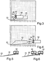
- Fig. 3 a schematic diagram is shown in which the sensor unit 23 is arranged at zero point.
- the horizontal axis indicates the distance to the rear, wherein the vertical axis represents the distance laterally to this sensor unit 23.
- the object 46 which represents a vehicle
- the number of received signals 47 to 51 is merely exemplary, but is reduced in comparison to the prior art in which, as shown in FIG Fig. 1 and transfer the situation in Fig. 3 on this system in Fig. 1 a significantly higher number of received signals would occur. This is the amount of data that is in Fig. 1 must be evaluated, much higher and the statement precision just at these specific positions relatively far laterally and relatively far forward with respect to the vehicle 21 is not improved.
- This embodiment is particularly advantageous with the corresponding number of detection signals whose orientation and a blind spot area 25 customary for a passenger vehicle according to the vehicle 21 ensure the best possible detection of further corresponding vehicles.
- This with regard to the usual widths in the range of 2 m of vehicles to be detected as objects in this respect also have corresponding blind spot areas, as shown in the figures.
- Fig. 4 a further diagram is shown, in which also the sensor unit 23 is arranged at zero point.
- the blind spot area 25 is analogous to the representation in FIG Fig. 3 ,
- an object 53 is still relatively far behind the vehicle 21 and thus also far behind the sensor unit 23, in which respect a distance of 14 m is formed.
- the sensors of the sensor unit 23 also generate detection signals 28 to 33, thus also detection signals 35 to 40 as well as detection signals 42 to 45, which extend beyond the blind spot area 25 and can detect correspondingly.
- objects 52 as they are in Fig. 4 are shown, which are arranged relatively far behind the vehicle 21 but relatively close to the vehicle longitudinal axis A, advantageous.
- a detection of the object 52 is therefore already possible when it is outside the blind spot area 25. This is also necessary for the reason that, with respect to the signal transmission, the signal propagation time, the received signals and the related evaluation, a time period passes during which the object 52 enters the blind spot area 25. This means that due to these circumstances, such an early detection is required in order to be able to make a corresponding statement in this regard when the object 52 actually enters the blind spot area 25.
- this specific horizontal angular widths b1, b2, b3 this is advantageous in that at usual vehicle widths already about 1.8 m from objects to be detected at a distance of about 15 m to the sensor unit 23 are detected accordingly.
- the detection signals 28 to 33 with their exemplary horizontal angular width b1 at a distance of 15 m to a horizontal signal width of 0.32 m. This can, as well as in Fig. 4 is shown, five detection signals detect the object 52 and corresponding reflected signals 53 to 57 are then received again.
- the reflected signals 53, 54, 55, 56 and 57 are shown.
- relative speeds between the object 52 and the vehicle 21 of 50 km / h are considered, with a reaction time of the driver assistance system 22 with respect to the transmission of the detection signals, their reception and processing 300 exemplified ms is.
- the illustration in FIG Fig. 4 it is therefore necessary to detect already 4.2 m after the end (at 10 m) of the blind spot area 25.
- a different design and termination is possible in this respect.
- Fig. 5 is shown in a further exemplary representation of the detection signal 28 which strikes an object 58 side.
- This narrow horizontal cross-section of the detection signal 28 creates a more accurate lateral detection of the object 58. Inaccuracies due to a too wide and possibly over the length of the object 58 protruding forward and backward detection signal 28 can be prevented, so that in this regard inaccuracies in the object detection can be avoided in comparison to the prior art.
- the detection signal 28 which can detect relatively accurately one of two relatively close to each other moving objects due to its small horizontal angular width. Due to the very narrow horizontal widening of the detection signal 28, it can be precisely determined in comparison with the prior art that the reflection from the object 60, which represents a vehicle, does not occur on the front object 50. In an embodiment according to Fig. 1 Such a detection would not be possible in the prior art because, due to the large horizontal width of the detection signals 5 close to the vehicle, the signal would impinge on the object 59 and the object 60 and a single long object would be detected in this respect.
Description
Die Erfindung betrifft ein Verfahren zum Erfassen eines Objekts in einem Totwinkelbereich eines Fahrzeugs, bei welchem mit einer Sensoreinheit eine Mehrzahl von Detektionssignalen eines Signalpakets ausgesendet und an dem Objekt reflektierte und von einer Empfangseinheit empfangene Signale ausgewertet werden. Des Weiteren betrifft die Erfindung ein Fahrerassistenzsystem zum Erfassen eines Objekts in einem Totwinkelbereich eines Fahrzeugs.The invention relates to a method for detecting an object in a blind spot area of a vehicle, in which a plurality of detection signals of a signal packet are emitted by a sensor unit and evaluated on the object and received by a receiving unit signals. Furthermore, the invention relates to a driver assistance system for detecting an object in a blind spot area of a vehicle.
Aus dem Stand der Technik sind Systeme für ein Fahrzeug bekannt, mittels denen Objekte in einem Totwinkelbereich des Fahrzeugs erfassbar sind. So zeigt diesbezüglich beispielsweise
In dem Patent
Die
Das Patent
In der
In der
Es ist Aufgabe der vorliegenden Erfindung, ein Verfahren sowie ein Fahrerassistenzsystem zu schaffen, bei dem die Objekterkennung in einem Totwinkelbereich eines Fahrzeugs verbessert werden kann.It is an object of the present invention to provide a method and a driver assistance system in which the object recognition in a blind spot area of a vehicle can be improved.
Diese Aufgabe wird durch ein Verfahren, welches die Merkmale nach Anspruch 1 aufweist, und ein Fahrerassistenzsystem, welches die Merkmale nach Anspruch 9 aufweist, gelöst.This object is achieved by a method having the features of
Bei dem erfindungsgemäßen Verfahren zum Erfassen eines Objekts in einem Totwinkelbereich eines Fahrzeugs wird mit einer Sensoreinheit eine Mehrzahl von Detektionssignalen eines Signalpakets ausgesendet und an dem Objekt reflektierte und von einer Empfangseinheit empfangene Signale werden ausgewertet. Zumindest zwei Detektionssignale werden dazu mit unterschiedlicher horizontaler Winkelbereite ausgesendet. Dies bedeutet, dass ein erstes Detektionssignal mit einer ersten horizontalen Winkelbreite ausgesendet wird und zumindest ein zweites Detektionssignal mit einer im Vergleich zur ersten horizontalen Winkelbreite unterschiedlichen horizontalen Winkelbreite ausgesendet wird. Durch diese Variation der horizontalen Winkelbreiten der unterschiedlichen Detektionssignale kann im Hinblick auf die Objekterkennung in unterschiedlichen Bereichen des Totwinkelfelds eine genauere Objekterkennung erfolgen. Durch diese Variation der horizontalen Winkelbreiten wird zum einen gerade bei relativ nahen und relativ weit seitlich im Totwinkelbereich zum Fahrzeug angeordneten Objekten die im Vergleich zum Stand der Technik hohe Datenmenge von Empfangssignalen reduziert, wobei auch mit dieser reduzierten Datenmenge eine Aussage über die Objekte mit gleicher Zuverlässigkeit und Sicherheit erfolgen kann. Darüber hinaus wird durch diese Variation der horizontalen Winkelbreite bei Objekten, die sich relativ weit hinter dem Fahrzeug befinden, eine Erhöhung der Datenmenge im Hinblick auf die empfangenen Informationen generiert, so dass diesbezüglich die Aussagegenauigkeit von erkannten Objekten gerade an diesen Positionen verbessert werden kann. Nicht zuletzt gewährleistet dies auch die Möglichkeit, dass bei relativ weit sich hinter dem Fahrzeug befindenden Objekten, die darüber hinaus auch noch im Hinblick auf die seitliche Betrachtung nah zum Fahrzeug angeordnet sind, sich die Aussagewahrscheinlichkeit ob sich lediglich ein oder mehrere Objekte hinter dem Fahrzeug befinden, wesentlich präzisiert werden kann.In the method according to the invention for detecting an object in a blind spot area of a vehicle, a plurality of detection signals of a signal packet are emitted with a sensor unit and signals reflected at the object and received by a receiving unit are evaluated. At least two detection signals are sent out with different horizontal angles. This means that a first detection signal having a first horizontal angular width is emitted and at least one second detection signal is emitted with a different horizontal angle width than the first horizontal angle width. As a result of this variation of the horizontal angular widths of the different detection signals, a more precise object recognition can take place with regard to the object recognition in different areas of the blind spot field. Due to this variation of the horizontal angular widths, the data volume of received signals which is high in comparison with the prior art is reduced, especially with relatively close objects arranged relatively far laterally in the blind spot range to the vehicle Statement about the objects can be made with equal reliability and security. In addition, this variation of the horizontal angle width for objects that are relatively far behind the vehicle, an increase in the amount of data generated in terms of the received information, so that in this regard the accuracy of the recognized objects can be improved precisely at these positions. Last but not least, this also ensures the possibility that with relatively far behind the vehicle objects, which are also arranged with respect to the lateral view close to the vehicle, the probability that only one or more objects are behind the vehicle , can be significantly specified.
Erfindungsgemäß wird eine erste Gruppe von Detektionssignalen mit einer ersten horizontalen Winkelbreite und eine zweite Gruppe von Detektionssignalen mit einer zur ersten unterschiedlichen zweiten horizontalen Winkelbreite ausgesendet. Durch derartige Gruppenbildung wird erreicht, dass erfindungsgemäß bei jeder Gruppe mehrere Detektionssignale ausgesendet werden und dadurch auch die Genauigkeit und Präzision der Objekterfassung verbessert wird.According to the invention, a first group of detection signals having a first horizontal angular width and a second group of detection signals having a second horizontal angular width different from the first are emitted. Such group formation ensures that, according to the invention, a plurality of detection signals are emitted for each group, thereby also improving the accuracy and precision of the object detection.
Erfindungsgemäß ist vorgesehen, dass jede Gruppe zumindest zwei Detektionssignale umfasst, die ausgesendet werden und die Detektionssignale einer Gruppe mit der gleichen horizontalen Winkelbreite ausgesendet werden. Es wird also innerhalb der Gruppe eine Aussendung von mehreren Detektionssignalen durchgeführt, die allesamt mit der gleichen Winkelbreite in horizontaler Richtung betrachtet erzeugt werden. Auch dadurch kann im Hinblick auf die Objekterfassung an unterschiedlichen Stellen des Totwinkelbereichs dies individuell präzisiert werden und gerade kritische örtliche Stellen im Totwinkelbereich im Hinblick auf die Objekterfassung präzisiert werden.According to the invention, it is provided that each group comprises at least two detection signals which are transmitted and the detection signals of a group with the same horizontal angular width are transmitted. Thus, a transmission of a plurality of detection signals is carried out within the group, all of which are generated with the same angular width in the horizontal direction. This also makes it possible to specify this individually with regard to the object detection at different points in the blind spot area, and to precisely specify critical local locations in the blind spot area with regard to the object detection.
Es kann vorgesehen sein, dass die Sensoreinheit eine Mehrzahl von ortsfesten unmittelbar nebeneinander angeordneten einzelnen Sensoren aufweist. Diese können ihre Detektionssignale gleichzeitig oder auch in zeitlich aufeinander folgender Weise aussenden. Werden sie zeitlich nacheinander ausgesendet, so ist vorzugsweise vorgesehen, dass dies mit einer Frequenz zwischen 12 Hz und 100 Hz erfolgt. Ein Signalpaket umfasst diesbezüglich alle gleichzeitig oder zeitlich nacheinander ausgesendeten Detektionssignale der Sensoreinheit, bei jeweils einmaliger Aussendung.It can be provided that the sensor unit has a plurality of stationary individual sensors arranged directly next to one another. These can emit their detection signals simultaneously or in chronological succession. If they are transmitted one after the other, it is preferably provided that this takes place at a frequency between 12 Hz and 100 Hz. In this regard, a signal packet includes all detection signals of the sensor unit emitted simultaneously or in succession, each time for a single transmission.
Vorzugsweise ist vorgesehen, dass die Sensoreinheit mehr als 5, insbesondere mehr als 10, insbesondere 16 Sensoren aufweist. Diese erzeugen jeweils ein Detektionssignal während eines Messzyklus, so dass sich bei einer derartigen Ausgestaltung ein Signalpaket aus 16 Detektionssignalen ergibt. In einem nachfolgenden zweiten Signalpaket werden dann wiederum jeweils ein Detektionssignal jedes Sensors ausgesendet usw.It is preferably provided that the sensor unit has more than 5, in particular more than 10, in particular 16 sensors. These each generate a detection signal during a measurement cycle, such that a signal packet of 16 detection signals results in such an embodiment. In a subsequent second signal packet, in turn, in each case a detection signal of each sensor is transmitted, etc.
Werden die Detektionssignale eines Signalpakets seitlich nacheinander von den jeweiligen Sensoren ausgesendet, so ist vorzugsweise vorgesehen, dass die Aussendung des Sendesignals mit dem Sensor beginnt, der das Sendesignal mit dem kleinsten Winkel gegenüber der Längsachse des Fahrzeugs aussendet. Diesbezüglich ist insbesondere auch vorgesehen, dass die Gruppe von Detektionssignalen zuerst ausgesendet wird, die die kleinsten horizontalen Winkelbreiten aufweisen.If the detection signals of a signal packet are emitted laterally successively by the respective sensors, then it is preferably provided that the transmission of the transmission signal begins with the sensor which emits the transmission signal with the smallest angle with respect to the longitudinal axis of the vehicle. In this regard, it is also provided in particular that the group of detection signals which have the smallest horizontal angular widths is first emitted.
Vorzugsweise ist vorgesehen, dass das Detektionssignal der zweiten Gruppe mit einer mindestens um 50 Prozent, insbesondere mindestens 90 Prozent, vorzugsweise zwischen 95 und 105 Prozent, insbesondere 100 Prozent, größeren horizontalen Winkelbreite als das Detektionssignal der ersten Gruppe ausgesendet wird. Diesbezüglich werden die horizontalen Winkelbreiten daher um einen sich wesentlich unterscheidenden Breitenwert ausgesendet. Dies trägt den vorab genannten Vorteilen besonders Rechnung.It is preferably provided that the detection signal of the second group is transmitted with an at least 50 percent, in particular at least 90 percent, preferably between 95 and 105 percent, in particular 100 percent, greater horizontal angle width than the detection signal of the first group. In this regard, therefore, the horizontal angular widths are emitted by a substantially different width value. This takes particular account of the aforementioned advantages.
Insbesondere wird vorgesehen, dass ein Detektionssignal der ersten Gruppe mit einer horizontalen Winkelbreite zwischen 1° und 2°, insbesondere zwischen 1 ° und 1,5°, ausgesendet wird. Besonders vorteilhaft ist in diesem Zusammenhang eine horizontale Winkelbreite von 1,25°. Durch derartig kleine bzw. horizontal betrachtet sehr schmale Sendesignale kann gerade die Detektion von Objekten relativ weit hinter einem Fahrzeug und im Hinblick auf die seitliche Position relativ nah zum Fahrzeug angeordneter Objekte einer größeren Menge von reflektierten Signalen, die dann als Empfangssignale empfangen werden, erzeugt werden. Dadurch kann die Datenmenge bei gerade derartigen Objekten an diesen spezifischen Positionen relativ zum Fahrzeug verbessert werden, wobei auch somit die Aussagepräzision bezüglich der Objekterkennung wesentlich verbessert werden kann. Insbesondere wird dadurch jedoch auch gewährleistet, dass wesentlich exakter erkannt werden kann, ob sich in diesen spezifischen örtlichen Stellen im Totwinkelbereich hinter dem Fahrzeug ein oder mehrere Objekte befinden. Die diesbezügliche Auflösungswahrscheinlichkeit mit den gewonnen Informationen ist wesentlich präzisiert.In particular, it is provided that a detection signal of the first group with a horizontal angular width between 1 ° and 2 °, in particular between 1 ° and 1.5 °, is emitted. Particularly advantageous in this context is a horizontal angular width of 1.25 °. By means of such small or very narrow transmission signals viewed horizontally, it is precisely the detection of objects relatively far behind a vehicle and with regard to the lateral position relatively close to the vehicle arranged objects of a larger amount of reflected signals, which are then received as received signals are generated , As a result, the data volume in the case of objects of this type can be improved at these specific positions relative to the vehicle, whereby the statement precision with regard to object recognition can thus be substantially improved. In particular, however, this also ensures that it can be detected much more accurately whether one or more objects are located in the blind spot area behind the vehicle in these specific local locations. The related probability of resolution with the information obtained is much more precise.
Vorzugsweise wird eine dritte Gruppe von Detektionssignalen mit einer horizontalen Winkelbreite größer der ersten und größer der zweiten Gruppe ausgesendet. Durch eine derartige weitere Spezifizierung und Aufteilung der Detektionssignale einer Sensoreinheit kann die Objekterkennung nochmals verbessert werden. Eine derartige Aufweitung der horizontalen Winkelbreite in der dritten Gruppe der Detektionssignale ist besonders vorteilhaft im Hinblick auf die relativ seitliche Abstrahlung dieser Detektionssignale, so dass diese Detektionssignale vorzugsweise mit einem relativ großen Winkel bezüglich ihrer Hauptabstrahlachse zur Fahrzeuglängsachse ausgesendet werden. In dem diese quasi sehr weit seitlich zum Fahrzeug ausgesendeten Detektionssignale mit einer deutlich vergrößerten Winkelbreite abgestrahlt werden, kann die Anzahl der reflektierten Signale, die dann auch empfangen werden reduziert werden, so dass bei Objekten in diesen örtlichen Gebieten des Totwinkelbereichs die gewonnene Informationsmenge von erhaltenen Empfangssignalen reduziert werden kann, jedoch dennoch die Aussagewahrscheinlichkeit einer Objekterkennung nicht beeinträchtigt wird.Preferably, a third group of detection signals with a horizontal angular width greater than the first and greater of the second group is transmitted. By such a further specification and division of the detection signals of a sensor unit, the object recognition can be further improved. Such a widening of the horizontal angular width in the third group of detection signals is particularly advantageous in view of the relatively lateral emission of these detection signals, so that these detection signals are preferably emitted at a relatively large angle with respect to their main emission axis to the vehicle longitudinal axis. By emitting these detection signals having a substantially increased angular width, which are emitted so to say very far to the side of the vehicle, the number of reflected signals which are then also received can be reduced, so that the objects of information obtained from received signals received in objects in these local areas of the blind spot area can be reduced, but the probability of object recognition is still not affected.
Es kann vorgesehen sein, dass die dritte Gruppe abhängig von der Ausgestaltung der Sensoreinheit gleichzeitig mit der ersten und/oder der zweiten Gruppe ausgesendet wird. Es kann auch vorgesehen sein, dass die Detektionssignale der dritten Gruppe seitlich unterschiedlich zu denen der ersten und/oder der zweiten Gruppe ausgesendet werden. Insbesondere ist dann bei einem derartig zeitlich versetzten Aussenden vorzugsweise vorgesehen, dass die dritte Gruppe zeitlich nach der ersten und nach der zweiten Gruppe ausgesendet wird. Auch hier kann diesbezüglich eine Taktfrequenz zwischen 12 Hz und 100 Hz für das gesamte Signalpaket vorzugsweise vorgesehen sein.It can be provided that the third group is emitted simultaneously with the first and / or the second group depending on the design of the sensor unit. It can also be provided that the detection signals of the third group differ laterally to which the first and / or the second group are sent. In particular, it is then preferably provided in the case of such a time-offset transmission that the third group is transmitted in time after the first and after the second group. Again, in this regard, a clock frequency between 12 Hz and 100 Hz may be preferably provided for the entire signal packet.
Insbesondere wird ein Detektionssignal der dritten Gruppe mit einer um mindestens 300 Prozent größeren, insbesondere zwischen 350 Prozent und 400 Prozent größeren horizontalen Winkelbreite als die Winkelbreite der ersten Gruppe ausgesendet. Auch diesbezüglich ist eine um ein Vielfaches größere horizontale Winkelbreite vorgesehen, was im Hinblick auf die Objekterfassung in Verbindung mit einer Datenreduzierung, die bezüglich der Objekterkennung auszuwerten ist, deutlich reduziert wird.In particular, a detection signal of the third group is transmitted with a horizontal angle width which is larger by at least 300 percent, in particular between 350 percent and 400 percent, than the angular width of the first group. Also in this regard, a larger by far greater horizontal angle width is provided, which is significantly reduced with respect to the object detection in conjunction with a data reduction, which is to be evaluated with respect to the object recognition.
Vorzugsweise wird auch von der dritten Gruppe eine Anzahl größer 1 von Detektionssignalen, insbesondere vier Detektionssignale ausgesendet. Besonders vorteilhaft ist vorgesehen, wenn die Anzahl der Detektionssignale der dritten Gruppe kleiner der Anzahl der Detektionssignale der ersten und/oder kleiner der Anzahl der zweiten Gruppe vorgegeben wird. Insbesondere wird vorgesehen, dass von der ersten und der zweiten Gruppe jeweils eine gleiche Anzahl größer 1, insbesondere 6, von Detektionssignalen ausgesendet wird. Gerade eine derartige Aufteilung von Detektionssignalen insbesondere in Verbindung mit den spezifischen Winkelbreiten bietet eine besonders optimierte Ausgestaltung im Hinblick auf eine präzise Objekterfassung in allen Gebieten des Totwinkelbereichs, wobei darüber hinaus die Objekterfassung mit gebietabhängig angepassten und geeignetsten Datenmengen generiert wird.Preferably, a number greater than 1 of detection signals, in particular four detection signals is also emitted by the third group. It is particularly advantageous if the number of detection signals of the third group is set smaller than the number of detection signals of the first and / or less than the number of the second group. In particular, it is provided that in each case an equal number greater than 1, in particular 6, of detection signals is emitted by the first and the second group. Especially such a division of detection signals, in particular in conjunction with the specific angular widths offers a particularly optimized design with regard to a precise object detection in all areas of the blind spot area, wherein moreover the object detection is generated with area-dependent adapted and most suitable amounts of data.
Erfindungsgemäß ist vorgesehen, dass ein Detektionssignal mit einer kleineren horizontalen Winkelbreite in einem kleineren Winkel zur Fahrzeuglängsachse ausgesendet wird als eine Detektionssignal mit einer größeren horizontalen Winkelbreite. Insbesondere wird vorgesehen, dass die horizontale Winkelbreite der Sendesignale mit zunehmendem Winkel zwischen der Fahrzeuglängsachse und der Hauptachse eines horizontalen Winkelbereichs eines Sendesignals zunimmt. Dies gilt für unterschiedliche Gruppen, so dass erfindungsgemäß die Detektionssignale einer Gruppe mit gleicher horizontaler Winkelbreite ausgesendet werden, obwohl sie unterschiedliche Winkel zur Fahrzeuglängsachse aufweisen.According to the invention, it is provided that a detection signal having a smaller horizontal angular width is transmitted at a smaller angle to the vehicle longitudinal axis than a detection signal having a larger horizontal angular width. In particular, it is provided that the horizontal angular width of the transmission signals increases with increasing angle between the vehicle longitudinal axis and the main axis of a horizontal angular range of a transmission signal. This applies to different groups, so that according to the invention, the detection signals of a group with the same horizontal angular width are transmitted, although they have different angles to the vehicle longitudinal axis.
Vorzugsweise sind daher die Detektionssignale der ersten Gruppe im Hinblick auf ihre Winkelorientierung zur Fahrzeuglängsachse näher dazu orientiert als die Detektionssignale der zweiten Gruppe und der dritten Gruppe.Preferably, therefore, the detection signals of the first group with respect to their angular orientation to the vehicle longitudinal axis are oriented closer thereto than the detection signals of the second group and the third group.
Bei einem erfindungsgemäßen Fahrerassistenzsystem zur Erfassung eines Objekts in einem Totwinkelbereich eines Fahrzeugs weist dieses System zumindest eine Sensoreinheit auf, welche zur Erzeugung einer Mehrzahl von Detektionssignalen eines Signalpakets ausgebildet ist. Das Fahrerassistenzsystem umfasst darüber hinaus eine Empfangseinheit, welche zur Auswertung von an dem Objekt reflektierten empfangenen Signalen ausgebildet ist. Zumindest zwei ausgesendete Detektionssignale weisen im Vergleich miteinander unterschiedliche horizontale Winkelbreiten auf.In a driver assistance system according to the invention for detecting an object in a blind spot area of a vehicle, this system has at least one sensor unit which is designed to generate a plurality of detection signals of a signal packet. The driver assistance system also includes a receiving unit, which is designed to evaluate received signals reflected at the object. At least two emitted detection signals have different horizontal angular widths as compared with each other.
Erfindungsgemäß ist vorgesehen, dass ein Detektionssignal mit einer kleineren horizontalen Winkelbreite in einem kleineren Abstandswinkel in Fahrzeugslängsachse ausgesendet ist als ein Detektionssignal mit einer größeren horizontalen Winkelbreite.According to the invention, it is provided that a detection signal having a smaller horizontal angular width is emitted at a smaller distance angle in the vehicle longitudinal axis than a detection signal having a larger horizontal angular width.
Erfindungsgemäß wird eine erste Gruppe von Detektionssignalen mit einer ersten horizontalen Winkelbreite und eine zweite Gruppe von Detektionssignalen mit einer zur ersten unterschiedlichen zweiten horizontalen Winkelbreite ausgesendet. Jede Gruppe umfasst zumindest zwei Detektionssignale und die Detektionssignale einer Gruppe werden mit der gleichen horizontalen Winkelbreite ausgesendet.According to the invention, a first group of detection signals having a first horizontal angular width and a second group of detection signals having a second horizontal angular width different from the first are emitted. Each group comprises at least two detection signals and the detection signals of a group are transmitted with the same horizontal angular width.
Vorteilhafte Ausgestaltungen des erfindungsgemäßen Verfahrens sind als vorteilhafte Ausgestaltungen des erfindungsgemäßen Fahrerassistenzsystems anzusehen.Advantageous embodiments of the method according to the invention are to be regarded as advantageous embodiments of the driver assistance system according to the invention.
Weitere Merkmale der Erfindung ergeben sich aus den Ansprüchen, den Figuren und der Figurenbeschreibung. Die vorstehend in der Beschreibung genannten Merkmale und Merkmalskombinationen sowie die nachfolgend in der Figurenbeschreibung genannten und/oder in den Figuren allein gezeigten Merkmale und Merkmalskombinationen sind nicht nur in der jeweils angegebenen Kombination, sondern auch in deren Kombinationen oder in Alleinstellung verwendbar, ohne den Rahmen der Erfindung zu verlassen.Further features of the invention will become apparent from the claims, the figures and the description of the figures. The features and feature combinations mentioned above in the description as well as the features and feature combinations mentioned below in the description of the figures and / or in the figures alone can be used not only in the respectively indicated combination but also in their combinations or in isolation, without the scope of To leave invention.
Ausführungsbeispiele der Erfindung werden nachfolgend anhand schematischer Zeichnungen näher erläutert. Es zeigen:
- Fig. 1
- eine schematische Draufsicht auf ein Fahrzeug mit einer Fahrerassistenzeinrichtung zum Erfassen von Objekten im Totwinkelbereich, wie es aus dem Stand der Technik bekannt ist;
- Fig. 2
- eine schematische Draufsicht auf ein Fahrzeug mit einem Ausführungsbeispiel eines erfindungsgemäßen Fahrerassistenzsystems;
- Fig. 3
- ein schematisches Diagramm bei dem ein Objekt in einer ersten Position relativ zum Fahrzeug gezeigt ist;
- Fig. 4
- ein Diagramm, bei dem das Objekt in einer zweiten Position relativ zum Fahrzeug gezeigt ist;
- Fig. 5
- eine Darstellung einer Objekterfassung mit einem Detektionssignal mit kleinster horizontaler Winkelbreite im Vergleich zu den anderen Sendesignalen des Ausführungsbeispiels; und
- Fig. 6
- eine Detektion eines von mehreren dicht hintereinander befindlichen Objekten mit einem Detektionssignal gemäß
Fig. 5 .
- Fig. 1
- a schematic plan view of a vehicle with a driver assistance device for detecting objects in the blind spot area, as is known from the prior art;
- Fig. 2
- a schematic plan view of a vehicle with an embodiment of a driver assistance system according to the invention;
- Fig. 3
- a schematic diagram in which an object is shown in a first position relative to the vehicle;
- Fig. 4
- a diagram in which the object is shown in a second position relative to the vehicle;
- Fig. 5
- a representation of an object detection with a detection signal with the smallest horizontal angular width compared to the other transmission signals the embodiment; and
- Fig. 6
- a detection of one of several closely spaced objects with a detection signal according to
Fig. 5 ,
In den Figuren werden gleiche oder funktionsgleiche Elemente mit den gleichen Bezugszeichen versehen.In the figures, identical or functionally identical elements are provided with the same reference numerals.
In
Darüber hinaus umfasst das Fahrerassistenzsystem 22 eine Steuer- und Auswerteeinheit 24, welche zur Auswertung der von den Sensoreinheiten 23 und 26 detektierten Signalen ausgebildet ist.In addition, the driver assistance system 22 includes a control and
Die Sensoreinheit 23 ist im Ausführungsbeispiel ein Sensor-Array mit einer Mehrzahl von einzelnen Infrarotsensoren. Im Ausführungsbeispiel ist vorgesehen, dass diesbezüglich 16 separate Infrarotsensoren vorgesehen sind, wobei die Anzahl diesbezüglich beispielhaft ist. Jede dieser einzelnen Sensoren der Sensoreinheit 23 ist zur Erzeugung eines Infrarotsignals als Detektionssignal ausgebildet. Dazu ist vorgesehen, dass Sensoren der Sensoreinheit 23 Detektionssignale einer ersten Gruppe 27 aussenden. Im Ausführungsbeispiel sind diesbezüglich sechs Sensoren vorgesehen, die jeweils ein Deteketionssignal 28, 29, 30, 31, 32 und 33 aussenden. Diese Detektionssignale 28 bis 33 sind die quasi am nächsten zum Fahrzeug 21 nach hinten abgestrahlten Detektionssignale. Dies bedeutet, dass sie möglichst fahrzeugnah und weit nach hinten ausgesendet werden. Diesbezüglich ist somit vorgesehen, dass diese Detektionssignale 28 bis 33 der ersten Gruppe 27 mit kleineren Winkeln ihrer Hauptabstrahlrichtung zur zum Fahrzeugrand hin verschobenen Achse A' der Fahrzeuglängsachse A orientiert sind. Beispielhaft ist der Winkel α eingezeichnet, welcher den Winkel zwischen der Achse A' und der Hauptrichtung des Detektionssignals 28 bezeichnet.In the exemplary embodiment, the
Darüber hinaus wird durch weitere Sensoren der Sensoreinheit 23 eine zweite Gruppe 34 von Detektionssignalen ausgesendet. Im Ausführungsbeispiel ist vorgesehen, dass diesbezüglich ebenfalls von sechs Sensoren Detektionssignale 35, 36, 37, 38, 39 und 40 ausgesendet werden. Die einzelnen Detektionssignale 35 bis 40 der zweiten Gruppe 34 weisen jeweils größere Winkel zu der Achse A' auf als die Detektionssignale 28 bis 33 der ersten Gruppe 27. Beispielhaft ist hier der Winkel β eingezeichnet, welcher den Winkel zwischen der Achse A' und der Hauptrichtung des Detektionssignals 35 bezeichnet, und welcher größer als der Winkel α sowie die nicht eingezeichneten jeweiligen Winkel zwischen den Detektionssignalen 29 bis 33 und der Achse A1' ist.In addition, a
Darüber hinaus wird eine dritte Gruppe 41 von Detektionssignalen ausgesendet. Die dritte Gruppe 41 umfasst im Ausführungsbeispiel vier Detektionssignale 42, 43, 44 und 45. Die Anzahl der Detektionssignale 42 bis 45 der dritten Gruppe 41 ist daher geringer als die Anzahl der Detektionssignale 28 bis 33 der ersten Gruppe 27 und auch der Detektionssignale 35 bis 40 der zweiten Gruppe 34. Beispielhaft ist der Winkel µ eingezeichnet, welcher den Winkel zwischen der Achse A' und der Hauptrichtung des Detektionssignals 42 bezeichnet. Der Winkel µ ist größer als die Winkel α und β.In addition, a
Die Detektionssignale aller drei Gruppen 27, 34 und 41 sind im Hinblick auf ihre Abstrahlrichtung so nebeneinander ausgebildet bzw. fächerartig aufgebaut, dass sie einen Gesamtbereich von etwa 40° im Hinblick auf die Winkelaufweitung abdecken.The detection signals of all three
Die vier Detektionssignale 42 bis 45 der dritten Gruppe 41 werden mit größeren Winkeln ihrer Hauptabstrahlrichtung zur Achse A' ausgesendet als die Detektionssignale der ersten Gruppe 27 und der zweiten Gruppe 34. Ausgehend von den Detektionssignalen 28 bis 33 der ersten Gruppe 27 werden die Detektionssignale 35 bis 40 der zweiten Gruppe 34 somit weiter seitlich nach außen in Bezug zum Fahrzeug 21 schräg nach hinten ausgesendet. Demgegenüber werden die Detektionssignale 42 bis 45 der dritten Gruppe 41 noch weiter seitlich schräg nach außen gerichtet im Bezug zum Fahrzeug 21 im Vergleich zu den Detektionssignalen der ersten Gruppe 27 und der zweiten Gruppe 34 ausgesendet.The four
Die horizontalen Winkelbreiten b1 der Detektionssignale der ersten Gruppe 27 sind unterschiedlich zur horizontalen Winkelbreite b2 der Detektionssignale der zweiten Gruppe 34 und auch unterschiedlich zur horizontalen Winkelbreite b3 der Detektionssignale der dritten Gruppe 41.The horizontal angular widths b1 of the detection signals of the
Im Ausführungsbeispiel ist vorgesehen, dass die Detektionssignale 28 bis 33 der ersten Gruppe 27 alle eine gleiche horizontale Winkelbreite b1 aufweisen. Eine horizontale Winkelbreite ist dabei dahingehend zu verstehen, dass sie den Winkel zwischen den zwei Signalbegrenzungen eines Detektionssignals 28 bis 33 darstellt. Im Hinblick auf eine horizontale Winkelbreite ist dabei die Signalkeulenweite zu verstehen, die sich in der Figurenebene und somit in der x-, y-Ebene ausbildet.In the exemplary embodiment, it is provided that the detection signals 28 to 33 of the
Im Ausführungsbeispiel ist vorgesehen, dass diese horizontale Winkelbreite b1 1,25° beträgt. Demgegenüber sind die Detektionssignale 35 bis 40 der zweiten Gruppe 34 mit einer im Vergleich zur horizontalen Winkelbreite b1 größeren horizontalen Winkelbreite b2 erzeugt. Auch hier sind alle Detektionssignale 35 bis 40 der zweiten Gruppe 34 mit dieser horizontalen Winkelbreite b2 abgestrahlt. Im Ausführungsbeispiel beträgt diese horizontale Winkelbreite b2 2,5°.In the exemplary embodiment, it is provided that this horizontal angular width b1 is 1.25 °. In contrast, the detection signals 35 to 40 of the
Die Detektionssignale 42 bis 45 der dritten Gruppe 41 sind demgegenüber mit einer dritten horizontalen Winkelbreite b3 erzeugt. Auch hier sind alle Detektionssignale 42 bis 45 mit dieser gleichen horizontalen Winkelbreite b3 erzeugt. Die horizontale Winkelbreite b3 beträgt im Ausführungsbeispiel 4,4°.In contrast, the detection signals 42 to 45 of the
Die horizontalen Winkelbreiten b1, b2, b3 sind allesamt unterschiedlich zu der horizontalen Winkelbreite b im Stand der Technik, welche 3° beträgt.The horizontal angular widths b1, b2, b3 are all different from the horizontal angular width b in the prior art, which is 3 °.
In analoger Ausgestaltung ist die Sensoreinheit 26 auf der linken Seite des Fahrzeugs 21 ausgebildet. Es kann vorgesehen sein, dass die Detektionssignale der drei Gruppen 27, 34 und 41 im wesentlichen gleichzeitig ausgesendet werden. Es kann jedoch auch vorgesehen sein, dass die Sensoreinheit 23 derartig ausgebildet ist; dass die Detektionssignale der ersten Gruppe 27 beispielsweise zeitlich vor den Detektionssignalen der zweiten Gruppe 34 und vor der dritten Gruppen 41 ausgesendet werden. Diesbezüglich kann dann auch vorgesehen sein, dass die Detektionssignale 28 bis 33 der ersten Gruppe 27 gleichzeitig ausgesendet werden. Ebenso kann vorgesehen sein, dass auch dann, wenn die Detektionssignale 28 bis 33 der ersten Gruppe 27 zeitlich vor denen der Gruppe 34 und der Gruppe 41 ausgesendet werden, auch diese Detektionssignale 28 bis 33 zeitlich nacheinander ausgesendet werden, wobei vorzugsweise dann zunächst das erste Detektionssignal 28 und in weiterer zeitlicher Reihenfolge dann die Detektionssignale 29 bis 33 folgend ausgesendet werden.In an analogous embodiment, the
Im Hinblick auf die Erzeugung der unterschiedlichen horizontalen Winkelbreiten b1, b2 und b3 können die jeweiligen Sensoren durch individuelle optischen Elemente vor einer Fotodiode entsprechend ausgerüstet werden, um die diesbezügliche Orientierung und Abstrahlcharakteristik erzielen zu können.With regard to the generation of the different horizontal angular widths b1, b2 and b3, the respective sensors can be equipped correspondingly by individual optical elements in front of a photodiode in order to be able to achieve the relevant orientation and emission characteristic.
Jeder der Sensoren der Sensoreinheit 23 umfasst darüber hinaus vorzugsweise eine Empfangseinheit, mittels welcher die an dem Erfassungsbereich der detektierten Objekten reflektierten Sendesignale empfangen werden.In addition, each of the sensors of the
Durch die Ausgestaltung der Sensoreinheit 23 gemäß der Darstellung in
Im Hinblick auf die Ausführung in
Im Hinblick auf die in
In
Im Hinblick auf die beispielhafte Anzahl von 16 Detektionssignalen in drei Gruppen gemäß der Darstellung in
Besonders vorteilhaft ist diese Ausführung mit der entsprechen Anzahl an Detektionssignalen, deren Orientierung und eines für einen Personenkraftwagen gemäß dem Fahrzeug 21 üblichen Totwinkelbereich 25 eine bestmögliche Detektierung von weiteren entsprechenden Fahrzeugen gewährleistet. Dies im Hinblick auf die üblichen Breiten im Bereich von 2 m von zu detektierenden Fahrzeugen als Objekte die diesbezüglich auch entsprechende Totwinkelbereiche aufweisen, wie sie in den Figuren dargestellt sind.This embodiment is particularly advantageous with the corresponding number of detection signals whose orientation and a
In
Im Vergleich zum Stand der Technik, bei dem bei einer derartigen Ausgestaltung lediglich zwei Signale reflektiert werden und somit eine zu geringe Datenmenge im Hinblick auf eine präzise Objekterkennung erzeugt werden, kann somit bei derartig relativ weit hinten und nah zum Fahrzeug 21 in seitlicher Richtung betrachtet angeordneten Objekten 52 durch die Erfindung eine größere Datenmenge im Hinblick auf die Aussage der Objekterkennung generiert werden.Compared to the prior art, in which only two signals are reflected in such an embodiment and thus a too small amount of data are generated with respect to a precise object recognition, thus arranged in such relatively far back and close to the
Diesbezüglich sind die reflektierten Signale 53, 54, 55, 56 und 57 gezeigt. Im Hinblick auf die Darstellung in
In
In
Claims (9)
- Method for sensing an object (46, 52, 58 to 60) in a blind spot region (25) of a vehicle (21), in which a sensor unit (23, 26) is used to transmit a plurality of detection signals (28 to 45) of a signal packet and if need be to evaluate signals that are reflected at the object (46, 52, 58 to 60) and received by the sensor unit (23, 26),
wherein
a first group (27) of detection signals (28 to 33) is transmitted with a first horizontal angle width (b1) and a second group (34) of detection signals (35 to 40) is transmitted with a second horizontal angle width (b2), which is different from the first, wherein
the first group (27) of detection signals (28 to 33) with a smaller horizontal angle width (b1) is transmitted at a smaller angle (α) in relation to the vehicle longitudinal axis (A, A') than the second group (34) of detection signals (35 to 40) with a larger horizontal angle width (b2), the larger horizontal angle width (b2) being larger than said smaller horizontal angle width (b1), wherein each group (27, 34) comprises at least two detection signals (28 to 40) and the detection signals (28 to 40) of a group (27, 34) are transmitted with the same horizontal angle width (b1, b2),
characterized in that
the detection signals (28 to 40) of a group (27, 34) have different angles (α) in relation to the vehicle longitudinal axis (A, A'). - Method according to Claim 1,
characterized in that
the detection signal (35 to 40) of the second group (34) is transmitted with a horizontal angle width (b2) that is larger by at least 50%, particularly at least 90%, preferably between 95% and 105%, than the detection signal (28 to 33) of the first group (27) . - Method according to Claim 1 or 2,
characterized in that
a detection signal (28 to 33) of the first group (27) is transmitted with a horizontal angle width (b1) of between 1° and 2°, particularly between 1° and 1.5°. - Method according to one of Claims 1 to 3,
characterized in that
a third group (41) of detection signals (42 to 45) is transmitted with a horizontal angle width (b3) larger than the horizontal angle width (b1) of the first group (27) and larger than the horizontal angle width (b2) of the second group (34). - Method according to Claim 4,
characterized in that
the third group (41) is transmitted at a time after the first (27) and the second (34) group or at the same time as the first (27) and/or the second (34) group. - Method according to Claim 4 or 5,
characterized in that
a detection signal (42 to 45) of the third group (41) is transmitted with a horizontal angle width (b3) that is larger by at least 300%, particularly larger by between 350% and 400%, than the horizontal angle width (b1) of the first group (27). - Method according to one of Claims 4 to 6,
characterized in that
the third group (41) transmits a number greater than one of detection signals (42 to 45), particularly four, and less than the number of the first (27) and/or the second (34) group. - Method according to one of Claims 1 to 7,
characterized in that
the first (27) and the second (34) group each transmit an identical number greater than one, particularly six, of detection signals (28 to 40). - Driver assistance system for sensing an object (46, 52, 58 to 60) in a blind spot region (25) of a vehicle (21) that has a sensor unit (23, 26), which is designed to produce a plurality of detection signals (28 to 45) of a signal packet, and has an evaluation unit (24), which is designed to evaluate received signals reflected at the object (46, 52, 58 to 60),
wherein
a first group (27) of detection signals (28 to 33) is transmitted with a first horizontal angle width (b1) and a second group (34) of detection signals (35 to 40) is transmitted with a second horizontal angle width (b2), which is different from the first, wherein
the first group (27) of detection signals (28 to 33) with a smaller horizontal angle width (b1) is transmitted at a smaller angle (α) in relation to the vehicle longitudinal axis (A, A') than the second group (34) of detection signals (35 to 40) with a larger horizontal angle width (b2), the larger horizontal angle width (b2) being larger than said smaller horizontal angle width (b1), wherein each group (27, 34) comprises at least two detection signals (28 to 40) and the detection signals (28 to 40) of a group (27, 34) are transmitted with the same horizontal angle width (b1, b2),
characterized in that
the detection signals (28 to 45) of a group (27, 34) have different angles (α) in relation to the vehicle longitudinal axis (A, A').
Applications Claiming Priority (1)
| Application Number | Priority Date | Filing Date | Title |
|---|---|---|---|
| DE102009052591A DE102009052591A1 (en) | 2009-11-10 | 2009-11-10 | Method for detecting an object in a blind spot area of a vehicle and driver assistance system for detecting an object in a blind spot area of a vehicle |
Publications (4)
| Publication Number | Publication Date |
|---|---|
| EP2320248A2 EP2320248A2 (en) | 2011-05-11 |
| EP2320248A3 EP2320248A3 (en) | 2011-11-16 |
| EP2320248B1 EP2320248B1 (en) | 2016-01-13 |
| EP2320248B2 true EP2320248B2 (en) | 2019-01-02 |
Family
ID=43558392
Family Applications (1)
| Application Number | Title | Priority Date | Filing Date |
|---|---|---|---|
| EP10013904.7A Active EP2320248B2 (en) | 2009-11-10 | 2010-10-23 | Method for detecting an object in the blind spot of a vehicle and driver assistance system for detecting an object in the blind spot of a vehicle |
Country Status (2)
| Country | Link |
|---|---|
| EP (1) | EP2320248B2 (en) |
| DE (1) | DE102009052591A1 (en) |
Families Citing this family (1)
| Publication number | Priority date | Publication date | Assignee | Title |
|---|---|---|---|---|
| DE102020109882A1 (en) | 2020-04-08 | 2021-10-14 | Stefan Sels | Sensor device for monitoring the blind spot area of a vehicle |
Family Cites Families (11)
| Publication number | Priority date | Publication date | Assignee | Title |
|---|---|---|---|---|
| DE3244358C2 (en) * | 1982-12-01 | 1984-10-04 | Daimler-Benz Ag, 7000 Stuttgart | Device for detecting obstacles as a maneuvering aid when parking or turning a motor vehicle |
| DE3635396A1 (en) * | 1986-10-17 | 1988-04-28 | Bayerische Motoren Werke Ag | DEVICE FOR DETECTING OBSTACLES FOR MOTOR VEHICLES |
| DE4343092A1 (en) * | 1993-12-17 | 1995-06-22 | Bayerische Motoren Werke Ag | Laser beam device for motor vehicles |
| US6363326B1 (en) * | 1997-11-05 | 2002-03-26 | Robert Lawrence Scully | Method and apparatus for detecting an object on a side of or backwards of a vehicle |
| DE19904043A1 (en) * | 1999-02-02 | 2000-08-03 | Valeo Schalter & Sensoren Gmbh | System and method for monitoring an area on the side of a vehicle |
| DE19927395A1 (en) | 1999-06-16 | 2001-01-04 | Daimler Chrysler Ag | Device and method for increasing the angular resolution of an antenna arrangement |
| US6452534B1 (en) * | 2000-08-04 | 2002-09-17 | Visteon Global Technologies, Inc. | Radar field-of-view enhancement method and apparatus for matching field-of-view to desired detection zone |
| DE10303578B4 (en) * | 2003-01-30 | 2015-08-13 | SMR Patents S.à.r.l. | Hazard detection system for vehicles with at least one side and rear environmental detection |
| DE102004019651A1 (en) | 2004-04-22 | 2005-11-17 | Siemens Ag | Blind spot sensor system |
| DE102005046000A1 (en) * | 2004-09-28 | 2006-05-04 | Continental Teves Ag & Co. Ohg | Device for detecting a lateral environment of a vehicle |
| JP4098318B2 (en) * | 2005-03-29 | 2008-06-11 | 本田技研工業株式会社 | Electronic scanning millimeter wave radar apparatus and computer program |
-
2009
- 2009-11-10 DE DE102009052591A patent/DE102009052591A1/en not_active Withdrawn
-
2010
- 2010-10-23 EP EP10013904.7A patent/EP2320248B2/en active Active
Also Published As
| Publication number | Publication date |
|---|---|
| EP2320248A2 (en) | 2011-05-11 |
| DE102009052591A1 (en) | 2011-05-12 |
| EP2320248B1 (en) | 2016-01-13 |
| EP2320248A3 (en) | 2011-11-16 |
Similar Documents
| Publication | Publication Date | Title |
|---|---|---|
| EP1910866B1 (en) | Method for determining the depth of a parking space using ultrasonic sensors and associated system | |
| EP1664838B1 (en) | Method and computer program for the detection of the contour of an obstacle in the surroundings of a vehicle | |
| DE102012021973A1 (en) | Method for operating a radar sensor of a motor vehicle, driver assistance device and motor vehicle | |
| DE102011012379B4 (en) | Method and radar sensor arrangement for detecting location and speed of objects relative to a vehicle | |
| DE102013008953B4 (en) | Method for operating a radar device of a vehicle, in particular of a motor vehicle, and radar device for a vehicle, in particular a motor vehicle | |
| DE102013218571A1 (en) | Device and method for lateral environment detection of a motor vehicle | |
| EP3811105A1 (en) | Method for calibrating a mimo radar sensor for motor vehicles | |
| EP2084554A1 (en) | Radar system for motor vehicles | |
| EP1801613B1 (en) | Method and device for detecting objects in the vicinity of a motor vehicle | |
| DE102010024328B4 (en) | Radar device with situation-adaptive modulation switching and control method | |
| WO2019038174A1 (en) | Avoidance of blind spot warnings as a result of spray | |
| EP3602119B1 (en) | Method for detecting an object in a surrounding area of a motor vehicle with classification of the object, ultrasonic sensor device and motor vehicle | |
| EP2895880B1 (en) | Method for function monitoring ultrasound sensors | |
| DE102010021053B3 (en) | Faults detecting method for measuring operation of ultrasound measuring arrangement of motor car, involves determining faults of measuring operation based on comparison of radius of object with velocity-dependent minimum radius | |
| EP1762861B1 (en) | Method and device for determining the geometry and position of a parking place | |
| EP2320248B2 (en) | Method for detecting an object in the blind spot of a vehicle and driver assistance system for detecting an object in the blind spot of a vehicle | |
| WO2004059341A1 (en) | Method for detecting environmental information and for determining the position of a parking space | |
| EP2607919A1 (en) | Method for contactless detection of an object in an environment of a vehicle, driver assistance device having an ultrasound sensor device and vehicle with such a driver assistance device | |
| DE102017115457A1 (en) | Detecting a misalignment of a distance sensor based on a ratio of detection features | |
| EP3018490B1 (en) | Method for detecting interference in a received signal in a radar sensor of a motor vehicle, computing device, driver assistance system, motor vehicle and computer program product | |
| EP2287630B1 (en) | Optoelectronic recording device | |
| DE102015009308B4 (en) | Method for operating a driver assistance system and motor vehicle | |
| WO2020011291A1 (en) | Detection of an incorrect position of a distance sensor on the basis of a ratio of detection characteristics | |
| DE102017218160B4 (en) | Method for operating a radar system of a motor vehicle and motor vehicle | |
| DE102017121570B3 (en) | Method for detecting an environmental region of a motor vehicle with specific echo reception durations in measurement cycles of ultrasound signals, as well as ultrasound sensor device and motor vehicle |
Legal Events
| Date | Code | Title | Description |
|---|---|---|---|
| PUAI | Public reference made under article 153(3) epc to a published international application that has entered the european phase |
Free format text: ORIGINAL CODE: 0009012 |
|
| AK | Designated contracting states |
Kind code of ref document: A2 Designated state(s): AL AT BE BG CH CY CZ DE DK EE ES FI FR GB GR HR HU IE IS IT LI LT LU LV MC MK MT NL NO PL PT RO RS SE SI SK SM TR |
|
| AX | Request for extension of the european patent |
Extension state: BA ME |
|
| PUAL | Search report despatched |
Free format text: ORIGINAL CODE: 0009013 |
|
| AK | Designated contracting states |
Kind code of ref document: A3 Designated state(s): AL AT BE BG CH CY CZ DE DK EE ES FI FR GB GR HR HU IE IS IT LI LT LU LV MC MK MT NL NO PL PT RO RS SE SI SK SM TR |
|
| AX | Request for extension of the european patent |
Extension state: BA ME |
|
| RIC1 | Information provided on ipc code assigned before grant |
Ipc: G01S 17/87 20060101ALI20111010BHEP Ipc: G01S 17/93 20060101AFI20111010BHEP |
|
| 17P | Request for examination filed |
Effective date: 20120515 |
|
| 17Q | First examination report despatched |
Effective date: 20120806 |
|
| REG | Reference to a national code |
Ref country code: DE Ref legal event code: R079 Ref document number: 502010010918 Country of ref document: DE Free format text: PREVIOUS MAIN CLASS: G01S0017930000 Ipc: G01S0017420000 |
|
| GRAP | Despatch of communication of intention to grant a patent |
Free format text: ORIGINAL CODE: EPIDOSNIGR1 |
|
| INTG | Intention to grant announced |
Effective date: 20150724 |
|
| RIC1 | Information provided on ipc code assigned before grant |
Ipc: G01S 13/93 20060101ALI20150710BHEP Ipc: G01S 17/93 20060101ALI20150710BHEP Ipc: G01S 17/42 20060101AFI20150710BHEP Ipc: G01S 17/87 20060101ALI20150710BHEP |
|
| GRAS | Grant fee paid |
Free format text: ORIGINAL CODE: EPIDOSNIGR3 |
|
| GRAA | (expected) grant |
Free format text: ORIGINAL CODE: 0009210 |
|
| AK | Designated contracting states |
Kind code of ref document: B1 Designated state(s): AL AT BE BG CH CY CZ DE DK EE ES FI FR GB GR HR HU IE IS IT LI LT LU LV MC MK MT NL NO PL PT RO RS SE SI SK SM TR |
|
| REG | Reference to a national code |
Ref country code: GB Ref legal event code: FG4D Free format text: NOT ENGLISH |
|
| REG | Reference to a national code |
Ref country code: CH Ref legal event code: EP |
|
| REG | Reference to a national code |
Ref country code: IE Ref legal event code: FG4D Free format text: LANGUAGE OF EP DOCUMENT: GERMAN |
|
| REG | Reference to a national code |
Ref country code: AT Ref legal event code: REF Ref document number: 770891 Country of ref document: AT Kind code of ref document: T Effective date: 20160215 |
|
| REG | Reference to a national code |
Ref country code: DE Ref legal event code: R096 Ref document number: 502010010918 Country of ref document: DE |
|
| REG | Reference to a national code |
Ref country code: LT Ref legal event code: MG4D |
|
| REG | Reference to a national code |
Ref country code: NL Ref legal event code: MP Effective date: 20160113 |
|
| PG25 | Lapsed in a contracting state [announced via postgrant information from national office to epo] |
Ref country code: NL Free format text: LAPSE BECAUSE OF FAILURE TO SUBMIT A TRANSLATION OF THE DESCRIPTION OR TO PAY THE FEE WITHIN THE PRESCRIBED TIME-LIMIT Effective date: 20160113 |
|
| PG25 | Lapsed in a contracting state [announced via postgrant information from national office to epo] |
Ref country code: FI Free format text: LAPSE BECAUSE OF FAILURE TO SUBMIT A TRANSLATION OF THE DESCRIPTION OR TO PAY THE FEE WITHIN THE PRESCRIBED TIME-LIMIT Effective date: 20160113 Ref country code: GR Free format text: LAPSE BECAUSE OF FAILURE TO SUBMIT A TRANSLATION OF THE DESCRIPTION OR TO PAY THE FEE WITHIN THE PRESCRIBED TIME-LIMIT Effective date: 20160414 Ref country code: NO Free format text: LAPSE BECAUSE OF FAILURE TO SUBMIT A TRANSLATION OF THE DESCRIPTION OR TO PAY THE FEE WITHIN THE PRESCRIBED TIME-LIMIT Effective date: 20160413 Ref country code: HR Free format text: LAPSE BECAUSE OF FAILURE TO SUBMIT A TRANSLATION OF THE DESCRIPTION OR TO PAY THE FEE WITHIN THE PRESCRIBED TIME-LIMIT Effective date: 20160113 Ref country code: ES Free format text: LAPSE BECAUSE OF FAILURE TO SUBMIT A TRANSLATION OF THE DESCRIPTION OR TO PAY THE FEE WITHIN THE PRESCRIBED TIME-LIMIT Effective date: 20160113 |
|
| PG25 | Lapsed in a contracting state [announced via postgrant information from national office to epo] |
Ref country code: RS Free format text: LAPSE BECAUSE OF FAILURE TO SUBMIT A TRANSLATION OF THE DESCRIPTION OR TO PAY THE FEE WITHIN THE PRESCRIBED TIME-LIMIT Effective date: 20160113 Ref country code: SE Free format text: LAPSE BECAUSE OF FAILURE TO SUBMIT A TRANSLATION OF THE DESCRIPTION OR TO PAY THE FEE WITHIN THE PRESCRIBED TIME-LIMIT Effective date: 20160113 Ref country code: LT Free format text: LAPSE BECAUSE OF FAILURE TO SUBMIT A TRANSLATION OF THE DESCRIPTION OR TO PAY THE FEE WITHIN THE PRESCRIBED TIME-LIMIT Effective date: 20160113 Ref country code: IS Free format text: LAPSE BECAUSE OF FAILURE TO SUBMIT A TRANSLATION OF THE DESCRIPTION OR TO PAY THE FEE WITHIN THE PRESCRIBED TIME-LIMIT Effective date: 20160513 Ref country code: PT Free format text: LAPSE BECAUSE OF FAILURE TO SUBMIT A TRANSLATION OF THE DESCRIPTION OR TO PAY THE FEE WITHIN THE PRESCRIBED TIME-LIMIT Effective date: 20160513 Ref country code: PL Free format text: LAPSE BECAUSE OF FAILURE TO SUBMIT A TRANSLATION OF THE DESCRIPTION OR TO PAY THE FEE WITHIN THE PRESCRIBED TIME-LIMIT Effective date: 20160113 Ref country code: LV Free format text: LAPSE BECAUSE OF FAILURE TO SUBMIT A TRANSLATION OF THE DESCRIPTION OR TO PAY THE FEE WITHIN THE PRESCRIBED TIME-LIMIT Effective date: 20160113 |
|
| REG | Reference to a national code |
Ref country code: DE Ref legal event code: R026 Ref document number: 502010010918 Country of ref document: DE |
|
| PLBI | Opposition filed |
Free format text: ORIGINAL CODE: 0009260 |
|
| REG | Reference to a national code |
Ref country code: FR Ref legal event code: PLFP Year of fee payment: 7 |
|
| PG25 | Lapsed in a contracting state [announced via postgrant information from national office to epo] |
Ref country code: DK Free format text: LAPSE BECAUSE OF FAILURE TO SUBMIT A TRANSLATION OF THE DESCRIPTION OR TO PAY THE FEE WITHIN THE PRESCRIBED TIME-LIMIT Effective date: 20160113 Ref country code: EE Free format text: LAPSE BECAUSE OF FAILURE TO SUBMIT A TRANSLATION OF THE DESCRIPTION OR TO PAY THE FEE WITHIN THE PRESCRIBED TIME-LIMIT Effective date: 20160113 |
|
| PLAX | Notice of opposition and request to file observation + time limit sent |
Free format text: ORIGINAL CODE: EPIDOSNOBS2 |
|
| 26 | Opposition filed |
Opponent name: CONTI TEMIC MICROELECTRONIC GMBH Effective date: 20161013 |
|
| PG25 | Lapsed in a contracting state [announced via postgrant information from national office to epo] |
Ref country code: SK Free format text: LAPSE BECAUSE OF FAILURE TO SUBMIT A TRANSLATION OF THE DESCRIPTION OR TO PAY THE FEE WITHIN THE PRESCRIBED TIME-LIMIT Effective date: 20160113 Ref country code: RO Free format text: LAPSE BECAUSE OF FAILURE TO SUBMIT A TRANSLATION OF THE DESCRIPTION OR TO PAY THE FEE WITHIN THE PRESCRIBED TIME-LIMIT Effective date: 20160113 Ref country code: CZ Free format text: LAPSE BECAUSE OF FAILURE TO SUBMIT A TRANSLATION OF THE DESCRIPTION OR TO PAY THE FEE WITHIN THE PRESCRIBED TIME-LIMIT Effective date: 20160113 Ref country code: SM Free format text: LAPSE BECAUSE OF FAILURE TO SUBMIT A TRANSLATION OF THE DESCRIPTION OR TO PAY THE FEE WITHIN THE PRESCRIBED TIME-LIMIT Effective date: 20160113 |
|
| PG25 | Lapsed in a contracting state [announced via postgrant information from national office to epo] |
Ref country code: BG Free format text: LAPSE BECAUSE OF FAILURE TO SUBMIT A TRANSLATION OF THE DESCRIPTION OR TO PAY THE FEE WITHIN THE PRESCRIBED TIME-LIMIT Effective date: 20160413 Ref country code: BE Free format text: LAPSE BECAUSE OF NON-PAYMENT OF DUE FEES Effective date: 20161031 Ref country code: SI Free format text: LAPSE BECAUSE OF FAILURE TO SUBMIT A TRANSLATION OF THE DESCRIPTION OR TO PAY THE FEE WITHIN THE PRESCRIBED TIME-LIMIT Effective date: 20160113 |
|
| PLBB | Reply of patent proprietor to notice(s) of opposition received |
Free format text: ORIGINAL CODE: EPIDOSNOBS3 |
|
| REG | Reference to a national code |
Ref country code: CH Ref legal event code: PL |
|
| REG | Reference to a national code |
Ref country code: IE Ref legal event code: MM4A |
|
| PG25 | Lapsed in a contracting state [announced via postgrant information from national office to epo] |
Ref country code: LI Free format text: LAPSE BECAUSE OF NON-PAYMENT OF DUE FEES Effective date: 20161031 Ref country code: CH Free format text: LAPSE BECAUSE OF NON-PAYMENT OF DUE FEES Effective date: 20161031 |
|
| PG25 | Lapsed in a contracting state [announced via postgrant information from national office to epo] |
Ref country code: LU Free format text: LAPSE BECAUSE OF NON-PAYMENT OF DUE FEES Effective date: 20161023 |
|
| REG | Reference to a national code |
Ref country code: FR Ref legal event code: PLFP Year of fee payment: 8 |
|
| PG25 | Lapsed in a contracting state [announced via postgrant information from national office to epo] |
Ref country code: IE Free format text: LAPSE BECAUSE OF NON-PAYMENT OF DUE FEES Effective date: 20161023 |
|
| REG | Reference to a national code |
Ref country code: BE Ref legal event code: MM Effective date: 20161031 |
|
| REG | Reference to a national code |
Ref country code: AT Ref legal event code: MM01 Ref document number: 770891 Country of ref document: AT Kind code of ref document: T Effective date: 20161023 |
|
| PG25 | Lapsed in a contracting state [announced via postgrant information from national office to epo] |
Ref country code: AT Free format text: LAPSE BECAUSE OF NON-PAYMENT OF DUE FEES Effective date: 20161023 |
|
| PG25 | Lapsed in a contracting state [announced via postgrant information from national office to epo] |
Ref country code: CY Free format text: LAPSE BECAUSE OF FAILURE TO SUBMIT A TRANSLATION OF THE DESCRIPTION OR TO PAY THE FEE WITHIN THE PRESCRIBED TIME-LIMIT Effective date: 20160113 Ref country code: HU Free format text: LAPSE BECAUSE OF FAILURE TO SUBMIT A TRANSLATION OF THE DESCRIPTION OR TO PAY THE FEE WITHIN THE PRESCRIBED TIME-LIMIT; INVALID AB INITIO Effective date: 20101023 |
|
| PG25 | Lapsed in a contracting state [announced via postgrant information from national office to epo] |
Ref country code: TR Free format text: LAPSE BECAUSE OF FAILURE TO SUBMIT A TRANSLATION OF THE DESCRIPTION OR TO PAY THE FEE WITHIN THE PRESCRIBED TIME-LIMIT Effective date: 20160113 Ref country code: MT Free format text: LAPSE BECAUSE OF FAILURE TO SUBMIT A TRANSLATION OF THE DESCRIPTION OR TO PAY THE FEE WITHIN THE PRESCRIBED TIME-LIMIT Effective date: 20160113 Ref country code: MC Free format text: LAPSE BECAUSE OF FAILURE TO SUBMIT A TRANSLATION OF THE DESCRIPTION OR TO PAY THE FEE WITHIN THE PRESCRIBED TIME-LIMIT Effective date: 20160113 Ref country code: MK Free format text: LAPSE BECAUSE OF FAILURE TO SUBMIT A TRANSLATION OF THE DESCRIPTION OR TO PAY THE FEE WITHIN THE PRESCRIBED TIME-LIMIT Effective date: 20160113 |
|
| REG | Reference to a national code |
Ref country code: FR Ref legal event code: PLFP Year of fee payment: 9 |
|
| PG25 | Lapsed in a contracting state [announced via postgrant information from national office to epo] |
Ref country code: AL Free format text: LAPSE BECAUSE OF FAILURE TO SUBMIT A TRANSLATION OF THE DESCRIPTION OR TO PAY THE FEE WITHIN THE PRESCRIBED TIME-LIMIT Effective date: 20160113 |
|
| PUAH | Patent maintained in amended form |
Free format text: ORIGINAL CODE: 0009272 |
|
| STAA | Information on the status of an ep patent application or granted ep patent |
Free format text: STATUS: PATENT MAINTAINED AS AMENDED |
|
| 27A | Patent maintained in amended form |
Effective date: 20190102 |
|
| AK | Designated contracting states |
Kind code of ref document: B2 Designated state(s): AL AT BE BG CH CY CZ DE DK EE ES FI FR GB GR HR HU IE IS IT LI LT LU LV MC MK MT NL NO PL PT RO RS SE SI SK SM TR |
|
| REG | Reference to a national code |
Ref country code: DE Ref legal event code: R102 Ref document number: 502010010918 Country of ref document: DE |
|
| P01 | Opt-out of the competence of the unified patent court (upc) registered |
Effective date: 20230528 |
|
| PGFP | Annual fee paid to national office [announced via postgrant information from national office to epo] |
Ref country code: GB Payment date: 20231019 Year of fee payment: 14 |
|
| PGFP | Annual fee paid to national office [announced via postgrant information from national office to epo] |
Ref country code: IT Payment date: 20231009 Year of fee payment: 14 Ref country code: FR Payment date: 20231023 Year of fee payment: 14 Ref country code: DE Payment date: 20231011 Year of fee payment: 14 |