EP2895880B1 - Method for function monitoring ultrasound sensors - Google Patents
Method for function monitoring ultrasound sensors Download PDFInfo
- Publication number
- EP2895880B1 EP2895880B1 EP13742238.2A EP13742238A EP2895880B1 EP 2895880 B1 EP2895880 B1 EP 2895880B1 EP 13742238 A EP13742238 A EP 13742238A EP 2895880 B1 EP2895880 B1 EP 2895880B1
- Authority
- EP
- European Patent Office
- Prior art keywords
- frequency
- ultrasonic
- vehicle
- movement
- ultrasonic sensor
- Prior art date
- Legal status (The legal status is an assumption and is not a legal conclusion. Google has not performed a legal analysis and makes no representation as to the accuracy of the status listed.)
- Active
Links
- 238000000034 method Methods 0.000 title claims description 39
- 238000012544 monitoring process Methods 0.000 title claims description 9
- 238000002604 ultrasonography Methods 0.000 title description 16
- 230000004044 response Effects 0.000 claims description 44
- 238000002592 echocardiography Methods 0.000 claims description 35
- 230000033001 locomotion Effects 0.000 claims description 33
- 238000005259 measurement Methods 0.000 claims description 32
- 238000004590 computer program Methods 0.000 claims description 6
- 230000007257 malfunction Effects 0.000 claims description 4
- 230000001419 dependent effect Effects 0.000 claims description 3
- 230000005540 biological transmission Effects 0.000 description 14
- 230000000694 effects Effects 0.000 description 14
- 230000006870 function Effects 0.000 description 8
- 238000012935 Averaging Methods 0.000 description 6
- 230000007423 decrease Effects 0.000 description 5
- 230000035945 sensitivity Effects 0.000 description 5
- 238000011109 contamination Methods 0.000 description 4
- 238000001514 detection method Methods 0.000 description 3
- 238000011156 evaluation Methods 0.000 description 3
- 230000008859 change Effects 0.000 description 2
- 230000007547 defect Effects 0.000 description 2
- 239000002689 soil Substances 0.000 description 2
- 238000012360 testing method Methods 0.000 description 2
- 230000009471 action Effects 0.000 description 1
- 230000032683 aging Effects 0.000 description 1
- 230000003679 aging effect Effects 0.000 description 1
- 230000006399 behavior Effects 0.000 description 1
- 230000000903 blocking effect Effects 0.000 description 1
- 238000004891 communication Methods 0.000 description 1
- 238000006073 displacement reaction Methods 0.000 description 1
- 238000009499 grossing Methods 0.000 description 1
- 230000001771 impaired effect Effects 0.000 description 1
- 230000010354 integration Effects 0.000 description 1
- 239000012528 membrane Substances 0.000 description 1
- 230000000704 physical effect Effects 0.000 description 1
- 230000008569 process Effects 0.000 description 1
- 238000012545 processing Methods 0.000 description 1
- 239000000758 substrate Substances 0.000 description 1
- 238000012795 verification Methods 0.000 description 1
Images

Classifications
-
- G—PHYSICS
- G01—MEASURING; TESTING
- G01S—RADIO DIRECTION-FINDING; RADIO NAVIGATION; DETERMINING DISTANCE OR VELOCITY BY USE OF RADIO WAVES; LOCATING OR PRESENCE-DETECTING BY USE OF THE REFLECTION OR RERADIATION OF RADIO WAVES; ANALOGOUS ARRANGEMENTS USING OTHER WAVES
- G01S15/00—Systems using the reflection or reradiation of acoustic waves, e.g. sonar systems
- G01S15/88—Sonar systems specially adapted for specific applications
- G01S15/93—Sonar systems specially adapted for specific applications for anti-collision purposes
- G01S15/931—Sonar systems specially adapted for specific applications for anti-collision purposes of land vehicles
-
- G—PHYSICS
- G01—MEASURING; TESTING
- G01S—RADIO DIRECTION-FINDING; RADIO NAVIGATION; DETERMINING DISTANCE OR VELOCITY BY USE OF RADIO WAVES; LOCATING OR PRESENCE-DETECTING BY USE OF THE REFLECTION OR RERADIATION OF RADIO WAVES; ANALOGOUS ARRANGEMENTS USING OTHER WAVES
- G01S15/00—Systems using the reflection or reradiation of acoustic waves, e.g. sonar systems
- G01S15/87—Combinations of sonar systems
-
- G—PHYSICS
- G01—MEASURING; TESTING
- G01S—RADIO DIRECTION-FINDING; RADIO NAVIGATION; DETERMINING DISTANCE OR VELOCITY BY USE OF RADIO WAVES; LOCATING OR PRESENCE-DETECTING BY USE OF THE REFLECTION OR RERADIATION OF RADIO WAVES; ANALOGOUS ARRANGEMENTS USING OTHER WAVES
- G01S7/00—Details of systems according to groups G01S13/00, G01S15/00, G01S17/00
- G01S7/52—Details of systems according to groups G01S13/00, G01S15/00, G01S17/00 of systems according to group G01S15/00
- G01S7/52004—Means for monitoring or calibrating
- G01S2007/52009—Means for monitoring or calibrating of sensor obstruction, e.g. dirt- or ice-coating
-
- G—PHYSICS
- G01—MEASURING; TESTING
- G01S—RADIO DIRECTION-FINDING; RADIO NAVIGATION; DETERMINING DISTANCE OR VELOCITY BY USE OF RADIO WAVES; LOCATING OR PRESENCE-DETECTING BY USE OF THE REFLECTION OR RERADIATION OF RADIO WAVES; ANALOGOUS ARRANGEMENTS USING OTHER WAVES
- G01S7/00—Details of systems according to groups G01S13/00, G01S15/00, G01S17/00
- G01S7/52—Details of systems according to groups G01S13/00, G01S15/00, G01S17/00 of systems according to group G01S15/00
- G01S7/52004—Means for monitoring or calibrating
- G01S2007/52012—Means for monitoring or calibrating involving a reference ground return
Definitions
- the invention relates to a method for monitoring the function of ultrasonic sensors of a vehicle, wherein the vehicle comprises at least one ultrasonic sensor, which is aligned parallel to the direction of movement, and at least one ultrasonic sensor, which is aligned perpendicular to the direction of movement. Furthermore, the invention relates to a computer program product and a device for carrying out the method.
- driver assistance systems which, with the aid of data about the surroundings of the vehicle, assist the driver in carrying out various driving maneuvers.
- These driver assistance systems include, for example, parking systems, which independently detect parking spaces and can lead the vehicle into the parking space.
- reversing assistants which check the travel path for obstacles while reversing.
- the systems mentioned need reliable sensors to obtain the most accurate image of the environment of the vehicle.
- ultrasonic sensors are used for this purpose.
- an ultrasound signal is emitted by a transmitter whose echo is registered by a receiver on the vehicle when it is reflected on an obstacle. From the time elapsed between transmission and reception of the signal and the known sound velocity, the distance between the vehicle and the reflective obstacle can be calculated.
- these measurements are carried out several times in succession with a plurality of ultrasonic sensors arranged on the vehicle.
- the ultrasonic sensors used can be damaged and impaired in their function, for example, by contamination or by physical action. This can lead to the image about the environment of the vehicle with which the Driver assistance systems work, is falsified. Therefore, it is necessary to timely detect a failure or malfunction of an ultrasonic sensor.
- a detection device for a vehicle in which the functionality of the example operating on ultrasound-based sensors is checked.
- the vehicle is equipped with several sensors whose signals are compared with each other.
- the transmit / receive range of this sensor is configured to receive bottom echoes, that is, ultrasound echoes reflected from the ground. If no echoes reflected by the ground are subsequently received, the respective sensor is recognized as inoperative.
- a detection device of a vehicle is known with a functional unit for transmitting and receiving signals. It is provided that the functional unit has at least a first and a further functional element whose signal inputs are compared to the determination of an associative Be subject to signal traffic, and in the absence of the signals in one of the functional elements, a configuration of its transmission / reception area on a road surface to be detected is carried out such that the corresponding functional element is inevitably set to functional reception of signal reflections
- a method for evaluating signals of an ultrasonic sensor wherein at a predetermined transmission time, a measurement signal emitted and received in response to the measurement signal at least one echo signal and evaluated, wherein during the evaluation of each received echo signal is compared with a threshold curve, wherein in a first Mode of operation of the course of the threshold curve is adjusted so that received echo signals whose amplitudes are below the threshold curve as noise components are detected and hidden, and received echo signals whose amplitudes are above the threshold curve, recognized as useful signal components and evaluated to determine distances to detected objects.
- the profile of the threshold curve is adjusted so that detected as ground reflectors noise components are detected from which a vehicle speed is determined relative to a road surface using the Doppler effect.
- a disadvantage of the prior art is that the known methods for checking the functionality of ultrasonic sensors based on the evaluation of ground echoes, but the expected amplitude of the ground echoes is not known, since the properties of the soil are unknown. Furthermore, it can only be determined with the methods known from the prior art whether an ultrasonic sensor can receive signals. A reduced sensitivity caused, for example, by contamination or aging of the sensor can not be detected by these methods. However, this would be desirable in order to give a warning before the complete failure of an ultrasonic sensor.
- a method for monitoring the function of ultrasonic sensors of a vehicle wherein the vehicle has at least one ultrasound sensor aligned parallel to the direction of movement and at least one ultrasound sensor which is perpendicular is aligned with the direction of movement, wherein the ultrasonic sensors emit ultrasonic signals with a frequency f 0 and wherein the ultrasonic sensors receive ground echoes reflected from the ground while driving, wherein a bottom echo is recorded as a reference signal with at least one aligned perpendicular to the direction of ultrasound sensor and with at least one parallel
- a Doppler-shifted bottom echo is recorded as a measurement signal and, depending on the Doppler frequency f 1 of the Doppler-shifted ground echo, a ratio of measurement signal and reference signal is formed and from at least two ratios determined at different Doppler frequencies f 1 the frequency response curve of the at least one parallel to the Movement direction aligned ultrasonic sensor is determined and wherein a malfunction of an ultrasonic sensor by deviations of the determined frequency response curve of a reference frequency response curve is detected.
- the vehicle is equipped with a variety of ultrasonic sensors, some of which are aligned parallel to the direction of movement, ie directed forward or backward. Other sensors are aligned perpendicular to the direction of movement of the vehicle, that is, the sensors are aligned from the vehicle to the left or to the right. All sensors send out ultrasonic signals with a frequency f 0 and then receive incoming ultrasonic echoes. From the signal propagation time the distance to the reflecting object is calculated.
- the frequencies of the ultrasonic echoes received by the forward or backward ultrasonic sensors change. This change is due to the Doppler effect and therefore only affects sensors that are aligned parallel to the direction of movement of the vehicle.
- the forward-facing sensors receive the bottom echoes at an increased frequency while the frequency of the bottom echoes received from the rear-facing sensors decreases.
- v 0 is the speed of sound
- f 1 is the Doppler frequency
- f 0 is the frequency of the transmitted ultrasonic signal.
- the sensors aligned to the sides that is to say the sensors oriented perpendicular to the direction of movement of the vehicle, are not influenced by the Doppler effect, so that the frequency of the received echoes essentially corresponds to the emitted frequency f 0 .
- the amplitude A 0 of a signal received from an ultrasonic sensor is influenced by the frequency response curve of the sensor and the frequency response curve of the filters used in the signal processing.
- the influences of these two frequency response curves are summarized and considered together as a frequency response curve H (f), so that the amplitude A 0 by the equation
- the Doppler shift interrogates another point in the frequency response curve, so the amplitude A 1 of the received Doppler shifted signal is given by:
- the sensitivity of the ultrasonic sensor is usually highest at the transmission frequency f 0 and increasingly decreases for deviating frequencies.
- the frequency response curve H has its maximum around the transmission frequency f 0 and decreases for deviating frequencies.
- the ultrasonic sensors directed to the left or to the right are not subject to the Doppler effect even when the vehicle is moving.
- the ratio A also gives the relative frequency response H (f 1 ): H (f 0 ).
- the ultrasonic sensors Since the ultrasonic sensors must also be able to receive ultrasonic echoes that do not occur at the transmission frequency f 0 due to the Doppler shift, it must be ensured that the ultrasonic sensor also reliably detects Doppler-shifted signals. For this purpose, while the vehicle is traveling at at least two different speeds v 1 with laterally oriented ultrasonic sensors, amplitude A 0 of ground echoes at the transmission frequency f 0 is measured as a reference value and in relation to the amplitudes A 1 of the Doppler-shifted ground echoes received by the ultrasound sensors aligned in the movement direction of the vehicle set.
- the curve A (f) which represents the ratio of the frequency response of a sensor arranged in the direction of movement to a sensor arranged perpendicular to the direction of movement, is then compared with a reference frequency response curve. In case of deviations that exceed a predetermined threshold, it is concluded that a malfunction of one of the participating ultrasonic sensors.
- the method for monitoring the function of the ultrasonic sensors is carried out in parallel to the normal operation of the ultrasonic sensors.
- the ground echoes of the ultrasound signals which are in any case emitted for the detection of the surroundings, are evaluated.
- the functional verification of the ultrasonic sensors does not restrict their availability.
- the amplitudes of the received ground echoes are within a predetermined range and / or if the signal times of the bottom echoes are within a predetermined range and otherwise the measurement is discarded.
- the amplitudes of the measurement signal which is formed by a bottom echo, which is detected by a sensor aligned parallel to the direction of movement, and the reference signal, which is detected by a sensor oriented perpendicular to the direction of movement, can vary greatly when the background is uneven. Furthermore, it is conceivable that in one or more sensors, the direct view of the ground is obstructed by nearby objects. In both cases, the received signals are not suitable for a determination of the frequency response curve. The latter case of a close object blocking the ultrasonic sensor can be detected over the life of the signal. If the runtime is shorter than the expected runtime, the measured value should be discarded. In the former case, a very uneven background leads to extreme amplitude fluctuations between the individual sensors. Another case is a background that reflects the ultrasonic signals poorly or not at all. Both cases can be excluded by comparing the received amplitudes with a predetermined allowable amplitude range.
- the relative frequency response curve A (f) of the at least one ultrasound sensor aligned parallel to the direction of movement is represented by a plurality of interpolation points at different assigned frequencies.
- a predetermined number N of nodes is evenly distributed over the frequency range to be considered and stored for each node a value of the frequency response curve A (f).
- the number of nodes is, for example, between 5 and 100 selected. The more nodes selected, the smaller the frequency spacing between the nodes.
- the interpolation points have a distance between 0.1 kHz and 1 kHz.
- the method is run through when the speed of the vehicle-dependent Doppler frequency f 1 of a received ground echo corresponds to a frequency F assigned to a node.
- an average value is formed from a plurality of measurements of the ratio A formed from the measurement signal and the reference signal.
- the averaging process prevents fluctuating properties of the soil from leading to strongly fluctuating measured values, since smoothing is achieved by averaging.
- the method can be carried out for each ultrasound sensor arranged on the vehicle, the relative frequency response curve A (f) being monitored separately for each sensor.
- the information can be stored in an array. It is conceivable, for example, to use a two-dimensional array in which a column contains the support points belonging to the frequency response curve of an ultrasonic sensor frequency response curve.
- the frequency range in which the frequency response curve of an ultrasonic sensor can be monitored depends on whether the sensor is oriented forwards or backwards and also depends on the maximum speed of the vehicle that is usually reached.
- the usually achieved highest speed of the vehicle limits the maximum achievable Doppler shift dt from the transmission frequency f 0 .
- a transmission frequency f 0 of 48 kHz and the known speed of sound of about 1235 km / h results in a maximum Doppler shift of about 11 kHz.
- the front sensor frequency is higher so that the observable range of the frequency response curve is from 48 kHz to 59 kHz, while the rear sensors experience a frequency shift to low frequencies, so that the observable range of the frequency response curve is between 37 kHz and 48 kHz.
- Another aspect of the invention is to provide a device for monitoring the operation of ultrasonic sensors of a vehicle, wherein the vehicle comprises at least one ultrasonic sensor which is aligned parallel to the direction of movement, at least one ultrasonic sensor, which is aligned perpendicular to the direction of movement, and a control device, wherein the control device is set up to emit ultrasonic signals at a frequency f 0 and to receive bottom echoes reflected by the ground while traveling with the ultrasonic sensors, wherein the control unit is set up to carry out the proposed method.
- a computer program is proposed according to which one of the methods described here is performed when the computer program is executed on a programmable computer device.
- the computer program can be stored on a machine-readable storage medium, for example on a permanent or rewritable storage medium or in association with a computer device or on a removable CD-ROM, DVD or USB stick.
- the computer program may be provided for download on a computing device such as a server, for example via a data network such as the Internet or a communication link such as a telephone line or a wireless link.
- the proposed method not only allows the complete failure of an ultrasonic sensor, which manifests itself as a lack of reception of a floor echo but already show a slight loss of sensitivity.
- the function of the ultrasonic sensor can be tested not only at the transmission frequency f 0 , but over the entire relevant frequency range for this sensor.
- the method according to the invention can advantageously be carried out in addition to the normal operation of the ultrasonic sensors without hindering them.
- the ultrasonic sensors of a vehicle can be continuously monitored without restricting their availability.
- Continuous monitoring of the ultrasonic sensors can also detect creeping effects such as those caused by aging effects or soiling.
- a measurement of an ultrasonic sensor not influenced by the Doppler effect is used as the reference signal.
- the different reflection behavior of the various possible substrates can be easily taken into account.
- incoming ground echoes are compared with a predetermined amplitude range and a predetermined signal propagation time.
- falsified measured values such as occur, for example, when the direct line of sight of an ultrasonic sensor to the ground is obscured by a near object or when the ground due to its nature only insufficiently reflects the ultrasonic signal, can be detected and discarded.
- FIG. 1 shows a vehicle on which a plurality of ultrasonic sensors are arranged.
- a vehicle 100 is shown on which twelve ultrasonic sensors are arranged in the embodiment shown.
- the ultrasonic sensors 1 to 6 are disposed at the front of the vehicle 100
- the ultrasonic sensors 7 to 12 are disposed at the rear of the vehicle 100.
- the ultrasonic sensors 1 to 6 arranged in the front region the ultrasonic sensors 2 to 5 are aligned forwardly, the ultrasonic sensor 1 is aligned to the left side, and the ultrasonic sensor 6 is aligned to the right side of the vehicle 100.
- the ultrasonic sensors 8 to 11 are aligned rearwardly, the ultrasonic sensor 12 is aligned to the left side of the vehicle 100, and the ultrasonic sensor 7 is aligned to the right side of the vehicle 100.
- the ultrasonic sensors 2 to 5 and 8 to 11 are aligned parallel to the moving direction of the vehicle 100.
- the direction of movement of the vehicle 100 is in FIG. 1 indicated by the reference numeral 102.
- the ultrasonic sensors 1, 6, 7 and 12 are aligned perpendicular to the direction of movement 102 of the vehicle 100.
- All ultrasonic sensors 1 to 12 are connected to a control unit 104 of the vehicle 100. By the control unit 104, the function of the ultrasonic sensors 1 to 12 of the vehicle 100 is monitored.
- This transmission frequency f 0 is usually chosen such that it corresponds to a resonance frequency of the ultrasonic sensors 1 to 12.
- the frequency f 0 is 48 kHz.
- a Ultrasound signal which was emitted from a forwardly oriented, that is aligned parallel to the direction of movement 102, ultrasonic sensor, provided with the reference numeral 120.
- An ultrasonic signal emitted by an ultrasonic sensor arranged on the right side of the vehicle 100 is provided with the reference numeral 110. If the ultrasonic signals 110, 120 hit the ground, they will be reflected.
- the bottom echo 122 of the forwardly emitted ultrasonic signal 120 is subject to the Doppler effect.
- the bottom echo 112 of the ultrasound signal 110 emitted to the right side of the vehicle 100 is not subject to the Doppler effect since the emission direction is perpendicular to the direction of movement 102 of the vehicle 100.
- the frequency of the bottom echo 112 is not shifted and therefore corresponds approximately to the original radiated frequency f 0 .
- the received ground echoes 112, 122 are evaluated by the control unit 104.
- the bottom echo 112 which is not subject to the Doppler effect, used as a reference signal and the bottom echo 122, which is measured due to the Doppler effect at a shifted frequency f 1 , used as a measurement signal.
- the control unit 104 checks whether the transit times of the bottom echoes 112, 122 and the measured amplitudes are plausible. For this purpose, it is checked whether the amplitudes of the bottom echoes 112, 122 are within a predetermined amplitude range and whether the signal propagation times of the bottom echoes 112, 122 are within a predetermined time interval.
- a ratio A is formed from the bottom echoes 112, 122 which aligns a relative amplitude of a sensor which is aligned parallel to the direction of movement 102 with a sensor which is perpendicular to the direction of movement of the vehicle 100 is, represents.
- This measurement is performed by the controller 104 at different speeds v 1 of the vehicle 100. From a large number of such measurements, the relative frequency response of an ultrasonic sensor 1 to 12 is determined. In the controller 104 are the the curves associated with the relative frequency response A (f) of the individual ultrasonic sensors 1 to 12 represented by support points.
- Each support point is assigned a frequency and a relative amplitude.
- the frequency is the Doppler-shifted frequency f 1 at which the Doppler-shifted bottom echo 122 was received.
- the relative amplitude corresponds to the ratio A between the measured value (amplitude of the Doppler-shifted bottom echo 122) and the reference value (amplitude of the non-Doppler-influenced bottom echo 112).
- the support points are stored in the form of a two-dimensional array, wherein the columns of the array each contain the relative amplitudes of the respective sensor associated support points.
- Each line of this array is assigned a different Doppler frequency.
- the frequency spacing between two nodes or two lines in the two-dimensional array depends on how many nodes N are used and which frequency range is covered. The size of the covered frequency range is limited by the maximum achievable Doppler shift. This in turn is dictated by the highest vehicle speed usually achieved. For example, at a transmission frequency f 0 and a maximum speed of 140 km / h, the maximum Doppler shift is about 11 kHz.
- the Doppler shift increases the frequency of the bottom echoes 122 received from the front sensors 2-5, thereby reducing the frequency of bottom echoes received from the rear sensors 8-11. Accordingly, for the front sensors 2 to 5, the frequency response curve can be monitored from the transmission frequency f 0 equal to 48 k / Hz to a frequency of 59 kHz (48 kHz + 11 kHz). Accordingly applies to the rear sensors 8 to 11, that their frequency response curve can be monitored in the range of 37 kHz to 48 kHz.
- the relative frequency response curve A (f) of the ultrasonic sensors 1 to 12 is represented by means of, for example, 20 interpolation points, and the maximum speed is 140 km / h, a frequency spacing of 0.55 kHz results between the interpolation points.
- a Doppler shift of 0.55 kHz corresponds to a vehicle speed of 7 km / h. Accordingly, it is advantageous with this choice, when the measurements always take place when the dependent on the vehicle speed v 1 Doppler shift corresponds to a frequency associated with a support point. This is the case here when the vehicle speed is a multiple of 7 km / h.
- averaging is particularly advantageous, in which newer measurements are weighted more heavily than older measurements.
- ⁇ is a constant between 0 and 1, which is usually chosen in the vicinity of 1.
- the relative frequency response curves A (f) of the respective ultrasonic sensors 1 to 12 are compared with a stored in the control unit 104 reference frequency response curve. It is possible to define a separate reference curve for each sensor. If deviations in a comparison between the measured relative frequency response curve and a reference frequency response curve stored in the memory of the control device 104 are detected by the control unit 104, a defect of the assigned ultrasound sensor is concluded. The controller 104 may then take appropriate action, such as informing the driver and / or turning off the corresponding ultrasonic sensor.
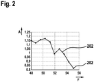
- FIG. 2 shows an example of a relative frequency response curve of an ultrasonic sensor.
- FIG. 2 a frequency response curve 200 of an ultrasonic sensor is shown.
- the frequency F is plotted on the x-axis, in the illustrated example from 48 kHz to 56 kHz.
- the relative amplitude is plotted, in which FIG. 2 As shown, the axis is divided from 0.8 to 1.25.
- the relative frequency response curve 200 in this example comprises support points 202, each of which is assigned a frequency and a relative amplitude.
- the frequency response curve 200 in the vicinity of the frequency f 0 equal to 48 kHz has its highest value, and decreases as the frequencies deviate from the resonant frequency of the sensor.
Description
Die Erfindung betrifft ein Verfahren zur Funktionsüberwachung von Ultraschallsensoren eines Fahrzeugs, wobei das Fahrzeug mindestens einen Ultraschallsensor, der parallel zur Bewegungsrichtung ausgerichtet ist, und mindestens einen Ultraschallsensor, der senkrecht zur Bewegungsrichtung ausgerichtet ist, umfasst. Des Weiteren betrifft die Erfindung ein Computerprogrammprodukt und eine Vorrichtung zur Durchführung des Verfahrens.The invention relates to a method for monitoring the function of ultrasonic sensors of a vehicle, wherein the vehicle comprises at least one ultrasonic sensor, which is aligned parallel to the direction of movement, and at least one ultrasonic sensor, which is aligned perpendicular to the direction of movement. Furthermore, the invention relates to a computer program product and a device for carrying out the method.
In modernen Fahrzeugen werden verschiedene Fahrassistenzsysteme eingesetzt, die mit Hilfe von Daten über die Umgebung des Fahrzeugs den Fahrer bei der Durchführung verschiedener Fahrmanöver unterstützen. Diese Fahrassistenzsysteme umfassen beispielsweise Einparksysteme, welche selbständig Parklücken erkennen und das Fahrzeug in die Parklücke führen können. Ein weiteres Beispiel sind Rückfahrassistenten, die den Fahrweg während des Rückwärtsfahrens auf Hindernisse überprüfen. Zur Erfüllung ihrer Aufgaben benötigen die genannten Systeme zuverlässige Sensoren, um ein möglichst genaues Abbild der Umgebung des Fahrzeugs zu erhalten. Häufig kommen dafür Ultraschallsensoren zum Einsatz. Dabei wird von einem Sender ein Ultraschallsignal ausgesendet, dessen Echo bei Reflexion an einem Hindernis von einem Empfänger am Fahrzeug registriert wird. Aus der Zeit, die zwischen Aussenden und Empfangen des Signals vergangen ist, und der bekannten Schallgeschwindigkeit kann der Abstand zwischen dem Fahrzeug und dem reflektierenden Hindernis berechnet werden. Um ein Abbild der Umgebung des Fahrzeugs zu erhalten, werden diese Messungen mehrfach hintereinander mit mehreren am Fahrzeug angeordneten Ultraschallsensoren ausgeführt.In modern vehicles, various driver assistance systems are used which, with the aid of data about the surroundings of the vehicle, assist the driver in carrying out various driving maneuvers. These driver assistance systems include, for example, parking systems, which independently detect parking spaces and can lead the vehicle into the parking space. Another example is reversing assistants, which check the travel path for obstacles while reversing. To perform their tasks, the systems mentioned need reliable sensors to obtain the most accurate image of the environment of the vehicle. Frequently, ultrasonic sensors are used for this purpose. In this case, an ultrasound signal is emitted by a transmitter whose echo is registered by a receiver on the vehicle when it is reflected on an obstacle. From the time elapsed between transmission and reception of the signal and the known sound velocity, the distance between the vehicle and the reflective obstacle can be calculated. In order to obtain an image of the surroundings of the vehicle, these measurements are carried out several times in succession with a plurality of ultrasonic sensors arranged on the vehicle.
Die verwendeten Ultraschallsensoren können jedoch beispielsweise durch Verschmutzung oder durch physikalische Einwirkung beschädigt und in ihrer Funktion beeinträchtigt werden. Dies kann dazu führen, dass das Abbild über die Umgebung des Fahrzeugs, mit dem die Fahrassistenzsysteme arbeiten, verfälscht ist. Daher ist es erforderlich, einen Ausfall oder eine Fehlfunktion eines Ultraschallsensors rechtzeitig zu erkennen.However, the ultrasonic sensors used can be damaged and impaired in their function, for example, by contamination or by physical action. This can lead to the image about the environment of the vehicle with which the Driver assistance systems work, is falsified. Therefore, it is necessary to timely detect a failure or malfunction of an ultrasonic sensor.
Aus
Aus
Aus
Aus
Aus
Nachteilig am Stand der Technik ist, dass die bekannten Verfahren zur Überprüfung der Funktionsfähigkeit von Ultraschallsensoren auf der Auswertung von Bodenechos beruhen, jedoch die zu erwartende Amplitude der Bodenechos nicht bekannt ist, da auch die Eigenschaften des Bodens unbekannt sind. Des Weiteren kann mit den aus dem Stand der Technik bekannten Verfahren nur ermittelt werden, ob ein Ultraschallsensor Signale empfangen kann. Eine beispielsweise durch Verschmutzung oder Alterung des Sensors verursachte verringerte Empfindlichkeit kann mit diesen Methoden nicht nachgewiesen werden. Dies wäre jedoch wünschenswert, um bereits vor dem völligen Ausfall eines Ultraschallsensors eine Warnung geben zu können.A disadvantage of the prior art is that the known methods for checking the functionality of ultrasonic sensors based on the evaluation of ground echoes, but the expected amplitude of the ground echoes is not known, since the properties of the soil are unknown. Furthermore, it can only be determined with the methods known from the prior art whether an ultrasonic sensor can receive signals. A reduced sensitivity caused, for example, by contamination or aging of the sensor can not be detected by these methods. However, this would be desirable in order to give a warning before the complete failure of an ultrasonic sensor.
Es wird ein Verfahren zur Funktionsüberwachung von Ultraschallsensoren eines Fahrzeugs vorgeschlagen, wobei das Fahrzeug mindestens einen Ultraschallsensor, der parallel zur Bewegungsrichtung ausgerichtet ist, und mindestens einen Ultraschallsensor, der senkrecht zur Bewegungsrichtung ausgerichtet ist, umfasst, wobei die Ultraschallsensoren Ultraschallsignale mit einer Frequenz f0 aussenden und wobei die Ultraschallsensoren während der Fahrt vom Boden reflektierte Bodenechos empfangen, wobei mit mindestens einem senkrecht zur Bewegungsrichtung ausgerichteten Ultraschallsensor ein Bodenecho als Referenzsignal aufgezeichnet wird und mit mindestens einem parallel zur Bewegungsrichtung ausgerichteten Ultraschallsensor ein dopplerverschobenes Bodenecho als Messsignal aufgezeichnet wird und wobei abhängig von der Doppler-Frequenz f1 des dopplerverschobenen Bodenechos ein Verhältnis aus Messsignal und Referenzsignal gebildet wird und aus mindestens zwei bei verschiedenen Dopplerfrequenzen f1 bestimmten Verhältnissen die Frequenzgangkurve des mindestens einen parallel zur Bewegungsrichtung ausgerichteten Ultraschallsensors ermittelt wird und wobei eine Fehlfunktion eines Ultraschallsensors durch Abweichungen der ermittelten Frequenzgangkurve von einer Referenzfrequenzgangkurve erkannt wird.A method for monitoring the function of ultrasonic sensors of a vehicle is proposed, wherein the vehicle has at least one ultrasound sensor aligned parallel to the direction of movement and at least one ultrasound sensor which is perpendicular is aligned with the direction of movement, wherein the ultrasonic sensors emit ultrasonic signals with a frequency f 0 and wherein the ultrasonic sensors receive ground echoes reflected from the ground while driving, wherein a bottom echo is recorded as a reference signal with at least one aligned perpendicular to the direction of ultrasound sensor and with at least one parallel A Doppler-shifted bottom echo is recorded as a measurement signal and, depending on the Doppler frequency f 1 of the Doppler-shifted ground echo, a ratio of measurement signal and reference signal is formed and from at least two ratios determined at different Doppler frequencies f 1 the frequency response curve of the at least one parallel to the Movement direction aligned ultrasonic sensor is determined and wherein a malfunction of an ultrasonic sensor by deviations of the determined frequency response curve of a reference frequency response curve is detected.
Das Fahrzeug ist mit einer Vielzahl von Ultraschallsensoren ausgerüstet, von denen einige parallel zur Bewegungsrichtung ausgerichtet sind, das heißt nach vorne oder nach hinten gerichtet sind. Weitere Sensoren sind senkrecht zur Bewegungsrichtung des Fahrzeugs ausgerichtet, das heißt die Sensoren sind vom Fahrzeug aus gesehen nach links oder nach rechts ausgerichtet. Alle Sensoren senden Ultraschallsignale mit einer Frequenz f0 aus und empfangen anschließend eingehende Ultraschallechos. Aus der Signallaufzeit wird dann der Abstand zum reflektierenden Objekt errechnet.The vehicle is equipped with a variety of ultrasonic sensors, some of which are aligned parallel to the direction of movement, ie directed forward or backward. Other sensors are aligned perpendicular to the direction of movement of the vehicle, that is, the sensors are aligned from the vehicle to the left or to the right. All sensors send out ultrasonic signals with a frequency f 0 and then receive incoming ultrasonic echoes. From the signal propagation time the distance to the reflecting object is calculated.
Bewegt sich das Fahrzeug, so verändern sich die Frequenzen der Ultraschallechos, die von den nach vorne oder nach hinten ausgerichteten Ultraschallsensoren empfangen werden. Diese Veränderung erfolgt aufgrund des Doppler-Effekts und wirkt daher nur auf Sensoren, die parallel zur Bewegungsrichtung des Fahrzeugs ausgerichtet sind. Die nach vorne ausgerichteten Sensoren empfangen die Bodenechos bei einer erhöhten Frequenz, während sich die Frequenz der von den nach hinten ausgerichteten Sensoren empfangenen Bodenechos verringert. Die Doppler-Frequenz f1 ergibt sich für die nach vorne ausgerichteten Ultraschallsensoren in Abhängigkeit der Fahrzeuggeschwindigkeit v1 zu : ![]()
![]()
Dabei ist v0 die Schallgeschwindigkeit, f1 die Doppler-Frequenz und f0 die Frequenz des ausgesendeten Ultraschallsignals. Für die hinteren Ultraschallsensoren ergibt sich die Dopplerfrequenz zu: ![]()
![]()
Die zu den Seiten ausgerichteten Sensoren, das heißt die senkrecht zur Bewegungsrichtung des Fahrzeugs ausgerichteten Sensoren, werden nicht durch den Doppler-Effekt beeinflusst, so dass die Frequenz der empfangenen Echos im Wesentlichen der ausgesendeten Frequenz f0 entspricht.The sensors aligned to the sides, that is to say the sensors oriented perpendicular to the direction of movement of the vehicle, are not influenced by the Doppler effect, so that the frequency of the received echoes essentially corresponds to the emitted frequency f 0 .
Die Amplitude A0 eines von einem Ultraschallsensor empfangenen Signals wird beeinflusst durch die Frequenzgangkurve des Sensors und der Frequenzgangkurve der verwendeten Filter in der Signalverarbeitung. Die Einflüsse dieser beiden Frequenzgangkurven werden zusammengefasst und gemeinsam als Frequenzgangkurve H (f) betrachtet, so dass die Amplitude A0 durch die Gleichung ![]()
![]()
![]()
![]()
Üblicherweise ist die Empfindlichkeit des Ultraschallsensors bei der Sendefrequenz f0 am höchsten und nimmt für abweichende Frequenzen zunehmend ab. Somit weist auch die Frequenzgangkurve H ihr Maximum um die Sendefrequenz f0 auf und verringert sich für davon abweichende Frequenzen.The sensitivity of the ultrasonic sensor is usually highest at the transmission frequency f 0 and increasingly decreases for deviating frequencies. Thus, the frequency response curve H has its maximum around the transmission frequency f 0 and decreases for deviating frequencies.
Aufgrund ihrer seitlichen Anordnung unterliegen die nach links bzw. nach rechts ausgerichteten Ultraschallsensoren auch bei Bewegung des Fahrzeugs nicht dem Doppler-Effekt. Dadurch eignen sich die von den seitlichen Ultraschallsensoren erfassten Bodenechos als Referenzmessung bei der Frequenz f0, mit der sich die erwartete Amplitude der Bodenechos bestimmen lässt. Aus dieser, nicht dem Doppler-Effekt unterliegender Amplitude A0 und der Amplitude A1 eines dem Doppler-Effekt unterliegenden Bodenechos, das heißt eine Messung eines nach vorne oder nach hinten ausgerichteten Ultraschallsensors, wird nun ein Verhältnis A gebildet: ![]()
![]()
Das Verhältnis A gibt dabei auch den relativen Frequenzgang H (f1): H (f0) wieder.The ratio A also gives the relative frequency response H (f 1 ): H (f 0 ).
Bei Stillstand des Fahrzeugs sind die Frequenzen f1 und f0 identisch, da keine Doppler-Verschiebung auftritt. Demnach ist unter der Voraussetzung, dass die Sensoren identisch sind, das Verhältnis A = 1. Ist einer der beiden verwendeten Sensoren stark beschädigt oder stark verschmutzt, wird das Verhältnis A deutlich vom Wert 1 abweichen und es kann bereits jetzt ein Defekt erkannt werden.At standstill of the vehicle, the frequencies f 1 and f 0 are identical, since no Doppler shift occurs. Accordingly, assuming that the sensors are identical, the ratio A = 1. If one of the two sensors used is severely damaged or heavily soiled, the ratio A will deviate significantly from the
Da die Ultraschallsensoren aufgrund der Dopplerverschiebung auch in der Lage sein müssen, Ultraschallechos zu empfangen, die nicht bei der Sendefrequenz f0 auftreten, muss jedoch sichergestellt sein, dass der Ultraschallsensor auch dopplerverschobene Signale zuverlässig erkennt. Dazu werden während der Fahrt des Fahrzeugs bei mindestens zwei verschiedenen Geschwindigkeiten v1 mit seitlich ausgerichteten Ultraschallsensoren Amplituden A0 von Bodenechos bei der Sendefrequenz f0 als Referenzwert gemessen und mit den Amplituden A1 der durch in Bewegungsrichtung des Fahrzeugs ausgerichteten Ultraschallsensoren empfangenen dopplerverschobenen Bodenechos in Verhältnis gesetzt. Die Kurve A(f), die das Verhältnis des Frequenzgangs eines in Bewegungsrichtung angeordneten Sensors zu einem senkrecht zur Bewegungsrichtung angeordneten Sensors darstellt, wird anschließend mit einer Referenzfrequenzgangkurve verglichen. Bei auftretenden Abweichungen, die über einen vorgegebenen Schwellenwert hinausgehen, wird auf eine Fehlfunktion eines der beteiligten Ultraschallsensoren geschlossen.Since the ultrasonic sensors must also be able to receive ultrasonic echoes that do not occur at the transmission frequency f 0 due to the Doppler shift, it must be ensured that the ultrasonic sensor also reliably detects Doppler-shifted signals. For this purpose, while the vehicle is traveling at at least two different speeds v 1 with laterally oriented ultrasonic sensors, amplitude A 0 of ground echoes at the transmission frequency f 0 is measured as a reference value and in relation to the amplitudes A 1 of the Doppler-shifted ground echoes received by the ultrasound sensors aligned in the movement direction of the vehicle set. The curve A (f), which represents the ratio of the frequency response of a sensor arranged in the direction of movement to a sensor arranged perpendicular to the direction of movement, is then compared with a reference frequency response curve. In case of deviations that exceed a predetermined threshold, it is concluded that a malfunction of one of the participating ultrasonic sensors.
In einer Ausführungsform des Verfahrens wird das Verfahren zur Funktionsüberwachung der Ultraschallsensoren parallel zum normalen Betrieb der Ultraschallsensoren durchgeführt.In one embodiment of the method, the method for monitoring the function of the ultrasonic sensors is carried out in parallel to the normal operation of the ultrasonic sensors.
Dabei werden die Bodenechos der ohnehin für die Erfassung der Umgebung ausgesendeten Ultraschallsignale ausgewertet. Auf dieses Weise wird durch die Funktionsüberprüfung der Ultraschallsensoren deren Verfügbarkeit nicht eingeschränkt.In this case, the ground echoes of the ultrasound signals, which are in any case emitted for the detection of the surroundings, are evaluated. In this way, the functional verification of the ultrasonic sensors does not restrict their availability.
In einer Ausführungsform des Verfahrens wird vor dem Bilden des Verhältnisses A aus Messsignal und Referenzsignal geprüft, ob die Amplituden der empfangenen Bodenechos innerhalb eines vorgegebenen Bereichs liegen und/oder ob die Signallaufzeiten der Bodenechos innerhalb eines vorgegebenen Bereichs liegen und andernfalls wird die Messung verworfen.In one embodiment of the method, prior to forming the ratio A of the measurement signal and the reference signal, it is checked whether the amplitudes of the received ground echoes are within a predetermined range and / or if the signal times of the bottom echoes are within a predetermined range and otherwise the measurement is discarded.
Die Amplituden des Messsignals, welches durch ein Bodenecho gebildet wird, welches von einem parallel zur Bewegungsrichtung ausgerichteten Sensors erfasst wird, und des Referenzsignals, welches von einem senkrecht zur Bewegungsrichtung ausgerichteten Sensor erfasst wird, können stark schwanken, wenn der Untergrund ungleichmäßig ist. Des Weiteren ist es denkbar, dass bei einem oder mehreren Sensoren die direkte Sicht zum Boden durch naheliegende Objekte versperrt ist. In beiden Fällen sind die empfangenen Signale für eine Bestimmung der Frequenzgangkurve nicht geeignet. Der letztere Fall, dass ein nahes Objekt den Ultraschallsensor blockiert, lässt sich über die Laufzeit des Signals ermitteln. Bei einer Laufzeit, die kürzer ist als die erwartete Laufzeit, sollte der Messwert verworfen werden. Im ersteren Fall führt ein stark ungleichmäßiger Untergrund zu extremen Amplitudenschwankungen zwischen den einzelnen Sensoren. Einen anderen Fall stellt ein Untergrund dar, der die Ultraschallsignale schlecht oder gar nicht reflektiert. Beide Fälle können durch einen Vergleich der empfangenen Amplituden mit einem vorgegebenen zulässigen Amplitudenbereich ausgeschlossen werden.The amplitudes of the measurement signal, which is formed by a bottom echo, which is detected by a sensor aligned parallel to the direction of movement, and the reference signal, which is detected by a sensor oriented perpendicular to the direction of movement, can vary greatly when the background is uneven. Furthermore, it is conceivable that in one or more sensors, the direct view of the ground is obstructed by nearby objects. In both cases, the received signals are not suitable for a determination of the frequency response curve. The latter case of a close object blocking the ultrasonic sensor can be detected over the life of the signal. If the runtime is shorter than the expected runtime, the measured value should be discarded. In the former case, a very uneven background leads to extreme amplitude fluctuations between the individual sensors. Another case is a background that reflects the ultrasonic signals poorly or not at all. Both cases can be excluded by comparing the received amplitudes with a predetermined allowable amplitude range.
In einer Ausführungsform des Verfahrens wird die relative Frequenzgangkurve A(f) des mindestens einen parallel zur Bewegungsrichtung ausgerichteten Ultraschallsensors über mehrere Stützstellen bei verschiedenen zugeordneten Frequenzen repräsentiert.In one embodiment of the method, the relative frequency response curve A (f) of the at least one ultrasound sensor aligned parallel to the direction of movement is represented by a plurality of interpolation points at different assigned frequencies.
Dabei wird eine vorgegebene Anzahl N von Stützstellen gleichmäßig über den zu betrachteten Frequenzbereich verteilt und zu jeder Stützstelle ein Wert der Frequenzgangkurve A(f) gespeichert. Die Anzahl der Stützstellen ist beispielsweise zwischen 5 und 100 gewählt. Je mehr Stützstellen gewählt werden, desto kleiner ist der Frequenzabstand zwischen den Stützstellen.In this case, a predetermined number N of nodes is evenly distributed over the frequency range to be considered and stored for each node a value of the frequency response curve A (f). The number of nodes is, for example, between 5 and 100 selected. The more nodes selected, the smaller the frequency spacing between the nodes.
In einer Ausführungsform des Verfahrens weisen die Stützstellen zueinander ein Abstand zwischen 0,1 kHz und 1 kHz auf.In one embodiment of the method, the interpolation points have a distance between 0.1 kHz and 1 kHz.
In einer Ausführungsform des Verfahrens wird das Verfahren dann durchlaufen, wenn die von der Geschwindigkeit des Fahrzeugs abhängige Doppler-Frequenz f1 eines empfangenen Bodenechos einer Frequenz F entspricht, die einer Stützstelle zugeordnet ist.In one embodiment of the method, the method is run through when the speed of the vehicle-dependent Doppler frequency f 1 of a received ground echo corresponds to a frequency F assigned to a node.
In einer bevorzugten Ausführungsform des Verfahrens wird aus mehreren Messungen des aus Messsignal und Referenzsignal gebildeten Verhältnisses A ein Mittelwert gebildet.In a preferred embodiment of the method, an average value is formed from a plurality of measurements of the ratio A formed from the measurement signal and the reference signal.
Mit der Mittelwertbildung wird verhindert, dass schwankende Eigenschaften des Bodens zu stark schwankenden Messwerten führen, da durch die Mittelung eine Glättung erfolgt.The averaging process prevents fluctuating properties of the soil from leading to strongly fluctuating measured values, since smoothing is achieved by averaging.
Bevorzugt ist es dabei, wenn bei der Mittelwertbildung neuere Messungen stärker gewichtet werden, als ältere Messungen.It is preferred in this case if newer measurements are weighted more heavily in the averaging than older measurements.
Das Verfahren kann für jeden am Fahrzeug angeordneten Ultraschallsensor durchgeführt werden, dabei wird für jeden Sensor getrennt die relative Frequenzgangkurve A(f) überwacht. Abhängig von der Anzahl der zu überwachenden Sensoren und der verwendeten Anzahl von Stützstellen, um die relative Frequenzgangkurve A(f) zu repräsentieren, können die Informationen in einem Array abgelegt werden. Denkbar ist es beispielsweise, ein zweidimensionales Array zu verwenden, bei dem eine Spalte die zur Frequenzgangkurve eines Ultraschallsensors gehörenden Stützstellen der Frequenzgangkurve enthält.The method can be carried out for each ultrasound sensor arranged on the vehicle, the relative frequency response curve A (f) being monitored separately for each sensor. Depending on the number of sensors to be monitored and the number of sample points used to represent the relative frequency response curve A (f), the information can be stored in an array. It is conceivable, for example, to use a two-dimensional array in which a column contains the support points belonging to the frequency response curve of an ultrasonic sensor frequency response curve.
Der Frequenzbereich, in dem die Frequenzgangkurve eines Ultraschallsensors überwacht werden kann, ist dabei davon abhängig, ob der Sensor nach vorne oder nach hinten ausgerichtet ist, und ist auch von der üblicherweise erreichten Höchstgeschwindigkeit des Fahrzeugs abhängig. Die üblicherweise erreichte höchste Geschwindigkeit des Fahrzeugs begrenzt die maximal erreichbare Doppler-Verschiebung dt von der Sendefrequenz f0. Beispielsweise für eine Höchstgeschwindigkeit des Fahrzeugs von 140 km/h, eine Sendefrequenz f0 von 48 kHz und der bekannten Schallgeschwindigkeit von etwa 1235 km/h ergibt sich eine maximale Doppler-Verschiebung von etwa 11 kHz. Dabei verschiebt sich die Frequenz bei den vorderen Sensoren nach oben, so dass der überwachbare Bereich der Frequenzgangkurve von 48 kHz bis 59 kHz liegt, während die hinteren Sensoren eine Frequenzverschiebung zu niedrigen Frequenzen erfahren, so dass der überwachbare Bereich der Frequenzgangkurve zwischen 37 kHz und 48 kHz liegt.The frequency range in which the frequency response curve of an ultrasonic sensor can be monitored depends on whether the sensor is oriented forwards or backwards and also depends on the maximum speed of the vehicle that is usually reached. The usually achieved highest speed of the vehicle limits the maximum achievable Doppler shift dt from the transmission frequency f 0 . For example, for a maximum speed of the vehicle of 140 km / h, a transmission frequency f 0 of 48 kHz and the known speed of sound of about 1235 km / h results in a maximum Doppler shift of about 11 kHz. It shifts the The front sensor frequency is higher so that the observable range of the frequency response curve is from 48 kHz to 59 kHz, while the rear sensors experience a frequency shift to low frequencies, so that the observable range of the frequency response curve is between 37 kHz and 48 kHz.
Dies stellt jedoch in der Praxis keine Einschränkung dar, da die überwachten Frequenzen genau den für den Fahrbetrieb wichtigen Frequenzen entsprechen und eine durch Verschmutzung oder Beschädigung des Sensors verursachte Verschiebung der Resonanzfrequenz sich in der Frequenzgangkurve sowohl oberhalb als auch unterhalb der Frequenz f0 bemerkbar macht.However, this does not constitute a limitation in practice, since the monitored frequencies correspond exactly to the frequencies important for the driving operation and a displacement of the resonance frequency caused by contamination or damage to the sensor becomes noticeable in the frequency response curve both above and below the frequency f 0 .
Ein weiterer Aspekt der Erfindung ist es, eine Vorrichtung zur Funktionsüberwachung von Ultraschallsensoren eines Fahrzeugs bereitzustellen, wobei das Fahrzeug mindestens einen Ultraschallsensor der parallel zur Bewegungsrichtung ausgerichtet ist, mindestens einen Ultraschallsensor, der senkrecht zur Bewegungsrichtung ausgerichtet ist, und ein Steuergerät umfasst, wobei das Steuergerät eingerichtet ist, während der Fahrt mit den Ultraschallsensoren Ultraschallsignale mit einer Frequenz f0 auszusenden und vom Boden reflektierte Bodenechos zu empfangen, wobei das Steuergerät eingerichtet ist das vorgeschlagene Verfahren auszuführen.Another aspect of the invention is to provide a device for monitoring the operation of ultrasonic sensors of a vehicle, wherein the vehicle comprises at least one ultrasonic sensor which is aligned parallel to the direction of movement, at least one ultrasonic sensor, which is aligned perpendicular to the direction of movement, and a control device, wherein the control device is set up to emit ultrasonic signals at a frequency f 0 and to receive bottom echoes reflected by the ground while traveling with the ultrasonic sensors, wherein the control unit is set up to carry out the proposed method.
Des Weiteren wird ein Computerprogramm vorgeschlagen, gemäß dem eines der hier beschriebenen Verfahren durchgeführt wird, wenn das Computerprogramm auf einer programmierbaren Computereinrichtung ausgeführt wird. Das Computerprogramm kann auf einem maschinenlesbaren Speichermedium gespeichert werden, etwa auf einem permanenten oder wiederbeschreibbaren Speichermedium oder in Zuordnung zu einer Computereinrichtung oder auf einer entfernbaren CD-Rom, DVD oder einen USB-Stick. Zusätzlich oder alternativ kann das Computerprogramm auf einer Computereinrichtung wie etwa auf einem Server zum Herunterladen bereitgestellt werden, zum Beispiel über ein Datennetzwerk wie das Internet oder eine Kommunikationsverbindung wie etwa eine Telefonleitung oder eine drahtlose Verbindung.Furthermore, a computer program is proposed according to which one of the methods described here is performed when the computer program is executed on a programmable computer device. The computer program can be stored on a machine-readable storage medium, for example on a permanent or rewritable storage medium or in association with a computer device or on a removable CD-ROM, DVD or USB stick. Additionally or alternatively, the computer program may be provided for download on a computing device such as a server, for example via a data network such as the Internet or a communication link such as a telephone line or a wireless link.
Mit dem vorgeschlagenen Verfahren lässt sich nicht nur der vollständige Ausfall eines Ultraschallsensors, der sich als ein Ausbleiben eines Empfangs eines Bodenechos äußern würde, sondern bereits ein geringer Empfindlichkeitsverlust nachweisen. Zudem lässt sich die Funktion des Ultraschallsensors nicht nur bei der Sendefrequenz f0, sondern über den gesamten für diesen Sensor relevanten Frequenzbereich testen. Durch einen Vergleich der durch das Verfahren ermittelten Frequenzgangkurve eines Sensors mit einer hinterlegten Referenzkurve lässt sich auch ein Empfindlichkeitsverlust bei anderen Frequenzen oder eine Verschiebung der Resonanzfrequenz des Sensors nachweisen. Auf diese Weise ist es möglich, ein Nachlassen der Empfindlichkeit des Sensors, zum Beispiel aufgrund von Verschmutzung, Brüchen in der Membran oder anderen physikalischen Beschädigungen, nachzuweisen, bevor der Sensor vollständig ausfällt.The proposed method not only allows the complete failure of an ultrasonic sensor, which manifests itself as a lack of reception of a floor echo but already show a slight loss of sensitivity. In addition, the function of the ultrasonic sensor can be tested not only at the transmission frequency f 0 , but over the entire relevant frequency range for this sensor. By comparing the frequency response curve of a sensor with a stored reference curve determined by the method, it is also possible to detect a loss of sensitivity at other frequencies or a shift in the resonance frequency of the sensor. In this way, it is possible to detect a decrease in the sensitivity of the sensor, for example due to contamination, breaks in the membrane or other physical damage, before the sensor fails completely.
Das erfindungsgemäße Verfahren kann vorteilhafterweise neben dem normalen Betrieb der Ultraschallsensoren durchgeführt werden, ohne diese zu behindern. Dadurch können die Ultraschallsensoren eines Fahrzeugs fortlaufend überwacht werden, ohne deren Verfügbarkeit einzuschränken.The method according to the invention can advantageously be carried out in addition to the normal operation of the ultrasonic sensors without hindering them. As a result, the ultrasonic sensors of a vehicle can be continuously monitored without restricting their availability.
Durch eine kontinuierliche Überwachung der Ultraschallsensoren können auch schleichende Effekte, wie sie durch Alterungseffekte oder Verschmutzung auftreten, erkannt werden.Continuous monitoring of the ultrasonic sensors can also detect creeping effects such as those caused by aging effects or soiling.
Ebenfalls vorteilhaft ist, dass als Referenzsignal eine Messung eines nicht durch den Doppler-Effekt beeinflussten Ultraschallsensors verwendet wird. Dadurch kann das unterschiedliche Reflexionsverhalten der verschiedenen möglichen Untergründe leicht berücksichtigt werden. Als zusätzliche Maßnahme ist des Weiteren vorgesehen, dass eingehende Bodenechos mit einem vorgegebenen Amplitudenbereich und einer vorgegebenen Signallaufzeit verglichen werden. Dadurch können verfälschte Messwerte, wie sie beispielsweise entstehen wenn die direkte Sichtlinie eines Ultraschallsensors zum Boden durch ein nahes Objekt verdeckt wird oder wenn der Boden aufgrund seiner Beschaffenheit das Ultraschallsignal nur unzureichend reflektiert, erkannt und verworfen werden.It is also advantageous that a measurement of an ultrasonic sensor not influenced by the Doppler effect is used as the reference signal. As a result, the different reflection behavior of the various possible substrates can be easily taken into account. As an additional measure, it is further provided that incoming ground echoes are compared with a predetermined amplitude range and a predetermined signal propagation time. As a result, falsified measured values, such as occur, for example, when the direct line of sight of an ultrasonic sensor to the ground is obscured by a near object or when the ground due to its nature only insufficiently reflects the ultrasonic signal, can be detected and discarded.
Des Weiteren ist vorteilhaft, dass zur Durchführung des vorgeschlagenen Verfahrens keine weiteren Komponenten am Fahrzeug angeordnet werden müssen. Dies erleichtert die Integration des Überwachungsverfahrens in bestehende technische Lösungen.Furthermore, it is advantageous that for carrying out the proposed method, no further components must be arranged on the vehicle. This facilitates the integration of the monitoring process into existing technical solutions.
Kurze Beschreibung der Zeichnungen
Figur 1- zeigt ein Fahrzeug, an dem eine Vielzahl von Ultraschallsensoren angebracht sind, deren Funktion mit dem vorgeschlagenen Verfahren überwacht wird,
Figur 2- zeigt eine gemessene Frequenzgangkurve eines parallel zur Bewegungsrichtung des Fahrzeugs ausgerichteten Ultraschallsensors.
- FIG. 1
- shows a vehicle on which a plurality of ultrasonic sensors are mounted, whose function is monitored by the proposed method,
- FIG. 2
- shows a measured frequency response curve of an aligned parallel to the direction of movement of the vehicle ultrasonic sensor.
In
Dementsprechend sind die Ultraschallsensoren 2 bis 5 und 8 bis 11 parallel zur Bewegungsrichtung des Fahrzeugs 100 ausgerichtet. Die Bewegungsrichtung des Fahrzeugs 100 ist in
Zur Überwachung der Ultraschallsensoren 1 bis 12 werden von diesen Ultraschallsignale 110, 120 bei einer Frequenz f0 ausgesendet. Diese Sendefrequenz f0 ist üblicherweise so gewählt, dass sie einer Resonanzfrequenz der Ultraschallsensoren 1 bis 12 entspricht. Beispielsweise beträgt die Frequenz f0 48 kHz. In dem in
Die empfangenen Bodenechos 112, 122 werden vom Steuergerät 104 ausgewertet. Dazu wird das Bodenecho 112, welches nicht dem Doppler-Effekt unterliegt, als Referenzsignal verwendet und das Bodenecho 122, welches aufgrund des Doppler-Effekts bei einer verschobenen Frequenz f1 gemessen wird, als Messsignal verwendet. Zunächst wird dabei vom Steuergerät 104 geprüft, ob die Laufzeiten der Bodenechos 112, 122 und die gemessenen Amplituden plausibel sind. Dazu wird geprüft, ob die Amplituden der Bodenechos 112, 122 innerhalb eines vorgegebenen Amplitudenbereichs liegen sowie ob die Signallaufzeiten der Bodenechos 112, 122 in einem vorgegebenen Zeitintervall liegen. Durch diese Vergleiche soll ausgeschlossen werden, dass anstelle eines Bodenechos 112, 122 das Echo eines nahen Objekts gemessen wird, welches die direkte Sicht eines Ultraschallsensors 1 bis 12 auf dem Boden verdeckt. Des Weiteren soll ausgeschlossen werden, dass aufgrund eines Untergrunds, der die Ultraschallsignale 110, 120 unzureichend reflektiert, auf einen fehlerhaften Sensor geschlossen wird.The received ground echoes 112, 122 are evaluated by the
Wurden die gemessenen Bodenechos 112, 122 als gültige Messdaten eingestuft, wird aus den Bodenechos 112, 122 ein Verhältnis A gebildet, welches eine relative Amplitude eines Sensors, der parallel zur Bewegungsrichtung 102 ausgerichtet ist zu einem Sensor, der senkrecht zur Bewegungsrichtung des Fahrzeugs 100 ausgerichtet ist, darstellt. Diese Messung wird durch das Steuergerät 104 bei verschiedenen Geschwindigkeiten v1 des Fahrzeugs 100 durchgeführt. Aus einer Vielzahl solcher Messungen wird der relative Frequenzgang eines Ultraschallsensors 1 bis 12 ermittelt. Im Steuergerät 104 werden die dem relativen Frequenzgang zugeordneten Kurven A(f) der einzelnen Ultraschallsensoren 1 bis 12 über Stützstellen repräsentiert. Je mehr Stützstellen N verwendet werden, desto präziser kann die relative Frequenzgangkurve A(f) eines Ultraschallsensors 1 bis 12 wiedergegeben werden. Jeder Stützstelle ist dabei eine Frequenz und eine relative Amplitude zugeordnet. Die Frequenz ist dabei die dopplerverschobene Frequenz f1, bei der das dopplerverschobene Bodenecho 122 empfangen wurde. Die relative Amplitude entspricht dem Verhältnis A zwischen dem Messwert (Amplitude des dopplerverschobenen Bodenechos 122) und dem Referenzwert (Amplitude des nicht dem Dopplereffekt unterliegenden Bodenechos 112).If the measured ground echoes 112, 122 have been classified as valid measurement data, a ratio A is formed from the bottom echoes 112, 122 which aligns a relative amplitude of a sensor which is aligned parallel to the direction of
Bevorzugt werden die Stützstellen in Form eines zweidimensionalen Arrays abgespeichert, wobei die Spalten des Arrays jeweils die relativen Amplituden der dem jeweiligen Sensor zugeordneten Stützstellen enthalten. Jeder Zeile dieses Arrays ist dabei eine andere Doppler-Frequenz zugeordnet. Der Frequenzabstand zwischen zwei Stützstellen bzw. zwei Zeilen in dem zweidimensionalen Array ist davon abhängig, wie viele Stützstellen N verwendet werden, und welcher Frequenzbereich abgedeckt wird. Die Größe des abgedeckten Frequenzbereichs ist durch die maximal erreichbare Doppler-Verschiebung begrenzt. Diese wiederum wird durch die höchste üblicherweise erreichte Fahrzeuggeschwindigkeit vorgegeben. Beispielsweise bei einer Sendefrequenz f0 und einer Höchstgeschwindigkeit von 140 km/h ist die maximale Dopplerverschiebung etwa 11 kHz. Durch die Doppler-Verschiebung erhöht sich die Frequenz der Bodenechos 122, die von den vorderen Sensoren 2 bis 5 empfangen werden, wobei sich die Frequenz von Bodenechos, die von den hinteren Sensoren 8 bis 11 empfangen werden, verringert. Dementsprechend lässt sich für die vorderen Sensoren 2 bis 5 die Frequenzgangkurve von der Sendefrequenz f0 gleich 48 k/Hz bis zu einer Frequenz von 59 kHz (48 kHz + 11 kHz) überwachen. Entsprechend gilt für die hinteren Sensoren 8 bis 11, dass deren Frequenzgangkurve im Bereich von 37 kHz bis 48 kHz überwacht werden kann.Preferably, the support points are stored in the form of a two-dimensional array, wherein the columns of the array each contain the relative amplitudes of the respective sensor associated support points. Each line of this array is assigned a different Doppler frequency. The frequency spacing between two nodes or two lines in the two-dimensional array depends on how many nodes N are used and which frequency range is covered. The size of the covered frequency range is limited by the maximum achievable Doppler shift. This in turn is dictated by the highest vehicle speed usually achieved. For example, at a transmission frequency f 0 and a maximum speed of 140 km / h, the maximum Doppler shift is about 11 kHz. The Doppler shift increases the frequency of the bottom echoes 122 received from the front sensors 2-5, thereby reducing the frequency of bottom echoes received from the rear sensors 8-11. Accordingly, for the
Wird die relative Frequenzgangkurve A(f) der Ultraschallsensoren 1 bis 12 mit Hilfe von beispielsweise 20 Stützstellen repräsentiert, und beträgt die Höchstgeschwindigkeit 140 km/h, ergibt sich zwischen den Stützstellen ein Frequenzabstand von 0,55 kHz. Bei diesem Beispiel entspricht eine Doppler-Verschiebung um 0,55 kHz einer Fahrzeuggeschwindigkeit von 7 km/h. Dementsprechend ist es bei dieser Wahl vorteilhaft, wenn die Messungen immer dann erfolgen, wenn die von der Fahrzeuggeschwindigkeit v1 abhängige Doppler-Verschiebung einer Frequenz entspricht, der eine Stützstelle zugeordnet ist. Dies ist hier der Fall, wenn die Fahrzeuggeschwindigkeit ein Vielfaches von 7 km/h ist.If the relative frequency response curve A (f) of the
Um Sprünge in den Messdaten zu vermeiden, beispielsweise verursacht durch Unregelmäßigkeiten im Untergrund, die zu Variationen in der Amplitude der Bodenechos 112, 122 führen, ist es bevorzugt, neue Messwerte nicht einfach an die entsprechende Stelle des Arrays zu schreiben, sondern eine Mittelwertbildung durchzuführen. Besonders vorteilhaft ist dabei eine Mittelwertbildung, bei der neuere Messungen stärker gewichtet werden, als ältere Messungen. Eine solche Mittelwertbildung kann beispielsweise über die Formel ![]()
![]()
Nachdem die relativen Frequenzgangkurven A(f) der jeweiligen Ultraschallsensoren 1 bis 12 ermittelt bzw. aktualisiert wurden, werden diese mit einer im Steuergerät 104 hinterlegten Referenzfrequenzgangkurve verglichen. Dabei ist es möglich, für jeden Sensor eine eigene Referenzkurve zu hinterlegen. Werden durch das Steuergerät 104 Abweichungen bei einem Vergleich zwischen der gemessenen relativen Frequenzgangkurve und einer im Speicher des Steuergeräts 104 hinterlegten Referenzfrequenzgangkurve festgestellt, wird auf einen Defekt des zugeordneten Ultraschallsensors geschlossen. Das Steuergerät 104 kann dann geeignete Maßnahmen treffen, wie beispielsweise den Fahrer informieren und/oder den entsprechenden Ultraschallsensor abschalten.After the relative frequency response curves A (f) of the respective
In
Wie der
Claims (10)
- Method for monitoring the function of ultrasonic sensors (1-12) of a vehicle (100), wherein the vehicle (100) comprises at least one ultrasonic sensor (2-5, 8-11)i oriented parallel to the direction of movement (102) and at least one ultrasonic sensor (1, 6, 7, 12) oriented perpendicular to the direction of movement (102), wherein the ultrasonic sensors (1-12) emit ultrasonic signals (110, 120) at a frequency f0, and wherein the ultrasonic sensors (1-12) receive ground echoes (112, 122) reflected by the ground during the journey, characterized in that at least one ultrasonic sensor (1, 6, 7, 12) oriented perpendicular to the direction of movement is used to record a ground echo (112) as a reference signal and at least one ultrasonic sensor (2-5, 8-11) oriented parallel to the direction of movement is used to record a Doppler-shifted ground echo (122) as a measurement signal, wherein a ratio (A) of the amplitude of the measurement signal and the amplitude of the reference signal is formed on the basis of the Doppler frequency f1 of the Doppler-shifted ground echo (122) and the frequency response curve (200) of the at least one ultrasonic sensor (2-5, 8-11) oriented parallel to the direction of movement is determined from at least two ratios (A) determined at different Doppler frequencies f1, and wherein a malfunction of an ultrasonic sensor (1-12) is detected by virtue of deviations of the determined frequency response curve (200) from a reference frequency response curve.
- Method according to Claim 1, characterized in that the method is carried out in a manner parallel to the normal operation of the ultrasonic sensors (1-12).
- Method according to Claim 1 or 2, characterized in that, before forming the ratio (A) of the amplitude of the measurement signal and the amplitude of the reference signal, a check is carried out in order to determine whether the amplitude of the received ground echoes (112, 122) is within a predefined range and/or in order to determine whether the signal propagation time of the ground echoes (112, 122) is within a predefined range and otherwise the measurement is rejected.
- Method according to one of Claims 1 to 3, characterized in that the frequency response curve (200) of the at least one ultrasonic sensor (2-5, 8-11) oriented parallel to the direction of movement is represented via a plurality of supporting points (202) at different assigned frequencies (F).
- Method according to Claim 4, characterized in that the supporting points (202) have a spacing of between 0.1 kHz and 1 kHz with respect to one another.
- Method according to Claim 4 or 5, characterized in that the method is run through when the Doppler frequency f1 of a received ground echo (122), which is dependent on the speed of the vehicle (100), corresponds to a frequency (F) assigned to a supporting point (202).
- Method according to one of Claims 1 to 6, characterized in that a mean value is formed from a plurality of measurements of the ratio (A) formed from the measurement signal and the reference signal.
- Method according to Claim 7, wherein newer measurements are given a higher weighting than older measurements when forming the mean value.
- Apparatus for monitoring the function of ultrasonic sensors (1-12) of a vehicle (100), wherein the vehicle (100) comprises at least one ultrasonic sensor (2-5, 8-11) oriented parallel to the direction of movement (102), at least one ultrasonic sensor (1, 6, 7, 12) oriented perpendicular to the direction of movement (102) and a control unit (104), wherein the control unit (104) is set up to use the ultrasonic sensors (1-12) to emit ultrasonic signals (110, 120) at a frequency f0 during the journey and to receive ground echoes (112, 122) reflected by the ground, characterized in that the control unit (104) is set up to carry out the method according to one of Claims 1 to 8.
- Computer program which carries out the method according to one of Claims 1 to 8 when it runs on a computer.
Applications Claiming Priority (2)
| Application Number | Priority Date | Filing Date | Title |
|---|---|---|---|
| DE102012216290.9A DE102012216290A1 (en) | 2012-09-13 | 2012-09-13 | Method for monitoring the function of ultrasonic sensors |
| PCT/EP2013/065962 WO2014040788A1 (en) | 2012-09-13 | 2013-07-30 | Method for function monitoring ultrasound sensors |
Publications (2)
| Publication Number | Publication Date |
|---|---|
| EP2895880A1 EP2895880A1 (en) | 2015-07-22 |
| EP2895880B1 true EP2895880B1 (en) | 2018-07-11 |
Family
ID=48877259
Family Applications (1)
| Application Number | Title | Priority Date | Filing Date |
|---|---|---|---|
| EP13742238.2A Active EP2895880B1 (en) | 2012-09-13 | 2013-07-30 | Method for function monitoring ultrasound sensors |
Country Status (3)
| Country | Link |
|---|---|
| EP (1) | EP2895880B1 (en) |
| DE (1) | DE102012216290A1 (en) |
| WO (1) | WO2014040788A1 (en) |
Families Citing this family (5)
| Publication number | Priority date | Publication date | Assignee | Title |
|---|---|---|---|---|
| DE102017115457A1 (en) * | 2017-07-11 | 2019-01-17 | Valeo Schalter Und Sensoren Gmbh | Detecting a misalignment of a distance sensor based on a ratio of detection features |
| DE102018205048A1 (en) * | 2018-04-04 | 2019-10-10 | Robert Bosch Gmbh | Method and device for monitoring the function of ultrasonic sensors |
| DE102018204996A1 (en) | 2018-04-04 | 2019-10-10 | Robert Bosch Gmbh | A method for improved detection of a ground echo signal in an ultrasonic sensor of a vehicle |
| DE102019119585A1 (en) * | 2019-07-19 | 2021-01-21 | Valeo Schalter Und Sensoren Gmbh | Determination of the installation location and the alignment of ultrasonic sensors by means of neural networks |
| DE102019119586A1 (en) * | 2019-07-19 | 2021-01-21 | Valeo Schalter Und Sensoren Gmbh | Alignment and installation position detection of ultrasonic sensors based on a statistical analysis of floor reflections |
Family Cites Families (5)
| Publication number | Priority date | Publication date | Assignee | Title |
|---|---|---|---|---|
| DE102005057973B4 (en) * | 2005-12-05 | 2017-02-23 | Robert Bosch Gmbh | Method for functional testing of an ultrasonic sensor and distance measuring device |
| DE102008004641A1 (en) | 2008-01-16 | 2009-07-23 | Robert Bosch Gmbh | Detection device of a vehicle and corresponding detection method |
| DE102009032124B4 (en) | 2009-07-08 | 2021-02-04 | Valeo Schalter Und Sensoren Gmbh | Method for recognizing a blocked state of a radar device and driver assistance device |
| DE102010003624B4 (en) * | 2010-04-01 | 2021-04-01 | Robert Bosch Gmbh | Method for detecting a fault in an ultrasonic transducer and fault detection device for an ultrasonic transducer |
| DE102010056439A1 (en) * | 2010-12-28 | 2012-06-28 | Valeo Schalter Und Sensoren Gmbh | Method for evaluating signals of an ultrasonic sensor and device for detecting surroundings in a vehicle |
-
2012
- 2012-09-13 DE DE102012216290.9A patent/DE102012216290A1/en not_active Withdrawn
-
2013
- 2013-07-30 EP EP13742238.2A patent/EP2895880B1/en active Active
- 2013-07-30 WO PCT/EP2013/065962 patent/WO2014040788A1/en active Application Filing
Non-Patent Citations (1)
| Title |
|---|
| None * |
Also Published As
| Publication number | Publication date |
|---|---|
| DE102012216290A1 (en) | 2014-03-13 |
| EP2895880A1 (en) | 2015-07-22 |
| WO2014040788A1 (en) | 2014-03-20 |
Similar Documents
| Publication | Publication Date | Title |
|---|---|---|
| EP3069166B1 (en) | Motor vehicle with occlusion detection for ultrasonic sensors | |
| EP2800982B1 (en) | Method and device for measuring the speed of a vehicle independently of the wheels | |
| EP3084470B1 (en) | Method for detecting target echoes in a received signal of an ultrasonic sensor of a motor vehicle, ultrasonic sensor device, and motor vehicle | |
| EP2191293B1 (en) | Object classification method, parking assistance method, and parking assistance system | |
| EP2081052B1 (en) | Detection device for a vehicle and relevant detection procedure | |
| EP2430474B1 (en) | Method for the functional testing of an ultrasonic sensor on a motor vehicle, method for operating an ultrasonic sensor on a motor vehicle, and distance measuring apparatus having at least one ultrasonic sensor for use in a motor vehicle | |
| EP1979763B1 (en) | Device and method for assisting a parking process of a vehicle | |
| EP2507648B1 (en) | Method for adjusting the sensitivity of ultrasonic sensors | |
| EP2895880B1 (en) | Method for function monitoring ultrasound sensors | |
| EP1947476A2 (en) | Method to support the parking procedure of a vehicle | |
| DE102013008953B4 (en) | Method for operating a radar device of a vehicle, in particular of a motor vehicle, and radar device for a vehicle, in particular a motor vehicle | |
| WO2015162132A1 (en) | Method for recognizing a blocked state of an ultrasonic sensor of a motor vehicle, ultrasonic sensor device, and motor vehicle | |
| WO2019038174A1 (en) | Avoidance of blind spot warnings as a result of spray | |
| DE102006043345B4 (en) | Method for carrying out distance measurements as a parking aid in motor vehicles | |
| EP2322952B1 (en) | Method for detecting an object, driver assistance device and vehicle with a driver assistance device | |
| EP2862004B1 (en) | Device and method for creating and evaluating ultrasound signals, in particular for determining the distance between an obstacle and a vehicle | |
| DE112017004938T5 (en) | Detection device, detection method and recording medium | |
| EP3602119B1 (en) | Method for detecting an object in a surrounding area of a motor vehicle with classification of the object, ultrasonic sensor device and motor vehicle | |
| DE102010021053B3 (en) | Faults detecting method for measuring operation of ultrasound measuring arrangement of motor car, involves determining faults of measuring operation based on comparison of radius of object with velocity-dependent minimum radius | |
| DE102014112917B4 (en) | A method for detecting a blocked state of an ultrasonic sensor, ultrasonic sensor device and motor vehicle | |
| EP3195009B1 (en) | Method for operating an ultrasonic sensor device of a motor vehicle, ultrasonic sensor device, driver assistance system, and motor vehicle | |
| DE102018103551B4 (en) | Method for characterizing an object in an area surrounding a motor vehicle using previously learned curve parameters, a sensor device and a driver assistance system | |
| WO2014095605A1 (en) | Method for the detection of a noise component in an electrical receive signal of an ultrasound sensor, ultrasound sensor device and motor vehicle | |
| DE102011121000A1 (en) | Method for determining threshold value curve for sensor of motor car, involves switching sensor to configuration mode to determine threshold value curve by which transmission signal is sent by sensor and a reception signal is received | |
| EP2813861B1 (en) | A method for determining a water level in the vicinity of a motor vehicle , driver assistance device and motor vehicle |
Legal Events
| Date | Code | Title | Description |
|---|---|---|---|
| PUAI | Public reference made under article 153(3) epc to a published international application that has entered the european phase |
Free format text: ORIGINAL CODE: 0009012 |
|
| 17P | Request for examination filed |
Effective date: 20150413 |
|
| AK | Designated contracting states |
Kind code of ref document: A1 Designated state(s): AL AT BE BG CH CY CZ DE DK EE ES FI FR GB GR HR HU IE IS IT LI LT LU LV MC MK MT NL NO PL PT RO RS SE SI SK SM TR |
|
| AX | Request for extension of the european patent |
Extension state: BA ME |
|
| DAX | Request for extension of the european patent (deleted) | ||
| GRAP | Despatch of communication of intention to grant a patent |
Free format text: ORIGINAL CODE: EPIDOSNIGR1 |
|
| INTG | Intention to grant announced |
Effective date: 20180226 |
|
| GRAA | (expected) grant |
Free format text: ORIGINAL CODE: 0009210 |
|
| AK | Designated contracting states |
Kind code of ref document: B1 Designated state(s): AL AT BE BG CH CY CZ DE DK EE ES FI FR GB GR HR HU IE IS IT LI LT LU LV MC MK MT NL NO PL PT RO RS SE SI SK SM TR |
|
| REG | Reference to a national code |
Ref country code: GB Ref legal event code: FG4D Free format text: NOT ENGLISH |
|
| REG | Reference to a national code |
Ref country code: CH Ref legal event code: EP |
|
| REG | Reference to a national code |
Ref country code: AT Ref legal event code: REF Ref document number: 1017480 Country of ref document: AT Kind code of ref document: T Effective date: 20180715 |
|
| GRAS | Grant fee paid |
Free format text: ORIGINAL CODE: EPIDOSNIGR3 |
|
| REG | Reference to a national code |
Ref country code: IE Ref legal event code: FG4D Free format text: LANGUAGE OF EP DOCUMENT: GERMAN |
|
| REG | Reference to a national code |
Ref country code: DE Ref legal event code: R096 Ref document number: 502013010597 Country of ref document: DE |
|
| REG | Reference to a national code |
Ref country code: FR Ref legal event code: PLFP Year of fee payment: 6 |
|
| REG | Reference to a national code |
Ref country code: NL Ref legal event code: MP Effective date: 20180711 |
|
| REG | Reference to a national code |
Ref country code: LT Ref legal event code: MG4D |
|
| PG25 | Lapsed in a contracting state [announced via postgrant information from national office to epo] |
Ref country code: NL Free format text: LAPSE BECAUSE OF FAILURE TO SUBMIT A TRANSLATION OF THE DESCRIPTION OR TO PAY THE FEE WITHIN THE PRESCRIBED TIME-LIMIT Effective date: 20180711 |
|
| PG25 | Lapsed in a contracting state [announced via postgrant information from national office to epo] |
Ref country code: FI Free format text: LAPSE BECAUSE OF FAILURE TO SUBMIT A TRANSLATION OF THE DESCRIPTION OR TO PAY THE FEE WITHIN THE PRESCRIBED TIME-LIMIT Effective date: 20180711 Ref country code: LT Free format text: LAPSE BECAUSE OF FAILURE TO SUBMIT A TRANSLATION OF THE DESCRIPTION OR TO PAY THE FEE WITHIN THE PRESCRIBED TIME-LIMIT Effective date: 20180711 Ref country code: PL Free format text: LAPSE BECAUSE OF FAILURE TO SUBMIT A TRANSLATION OF THE DESCRIPTION OR TO PAY THE FEE WITHIN THE PRESCRIBED TIME-LIMIT Effective date: 20180711 Ref country code: SE Free format text: LAPSE BECAUSE OF FAILURE TO SUBMIT A TRANSLATION OF THE DESCRIPTION OR TO PAY THE FEE WITHIN THE PRESCRIBED TIME-LIMIT Effective date: 20180711 Ref country code: BG Free format text: LAPSE BECAUSE OF FAILURE TO SUBMIT A TRANSLATION OF THE DESCRIPTION OR TO PAY THE FEE WITHIN THE PRESCRIBED TIME-LIMIT Effective date: 20181011 Ref country code: RS Free format text: LAPSE BECAUSE OF FAILURE TO SUBMIT A TRANSLATION OF THE DESCRIPTION OR TO PAY THE FEE WITHIN THE PRESCRIBED TIME-LIMIT Effective date: 20180711 Ref country code: GR Free format text: LAPSE BECAUSE OF FAILURE TO SUBMIT A TRANSLATION OF THE DESCRIPTION OR TO PAY THE FEE WITHIN THE PRESCRIBED TIME-LIMIT Effective date: 20181012 Ref country code: IS Free format text: LAPSE BECAUSE OF FAILURE TO SUBMIT A TRANSLATION OF THE DESCRIPTION OR TO PAY THE FEE WITHIN THE PRESCRIBED TIME-LIMIT Effective date: 20181111 Ref country code: NO Free format text: LAPSE BECAUSE OF FAILURE TO SUBMIT A TRANSLATION OF THE DESCRIPTION OR TO PAY THE FEE WITHIN THE PRESCRIBED TIME-LIMIT Effective date: 20181011 |
|
| PG25 | Lapsed in a contracting state [announced via postgrant information from national office to epo] |
Ref country code: HR Free format text: LAPSE BECAUSE OF FAILURE TO SUBMIT A TRANSLATION OF THE DESCRIPTION OR TO PAY THE FEE WITHIN THE PRESCRIBED TIME-LIMIT Effective date: 20180711 Ref country code: ES Free format text: LAPSE BECAUSE OF FAILURE TO SUBMIT A TRANSLATION OF THE DESCRIPTION OR TO PAY THE FEE WITHIN THE PRESCRIBED TIME-LIMIT Effective date: 20180711 Ref country code: AL Free format text: LAPSE BECAUSE OF FAILURE TO SUBMIT A TRANSLATION OF THE DESCRIPTION OR TO PAY THE FEE WITHIN THE PRESCRIBED TIME-LIMIT Effective date: 20180711 Ref country code: LV Free format text: LAPSE BECAUSE OF FAILURE TO SUBMIT A TRANSLATION OF THE DESCRIPTION OR TO PAY THE FEE WITHIN THE PRESCRIBED TIME-LIMIT Effective date: 20180711 |
|
| REG | Reference to a national code |
Ref country code: CH Ref legal event code: PL |
|
| PG25 | Lapsed in a contracting state [announced via postgrant information from national office to epo] |
Ref country code: LU Free format text: LAPSE BECAUSE OF NON-PAYMENT OF DUE FEES Effective date: 20180730 |
|
| REG | Reference to a national code |
Ref country code: BE Ref legal event code: MM Effective date: 20180731 |
|
| REG | Reference to a national code |
Ref country code: DE Ref legal event code: R097 Ref document number: 502013010597 Country of ref document: DE |
|
| PG25 | Lapsed in a contracting state [announced via postgrant information from national office to epo] |
Ref country code: CZ Free format text: LAPSE BECAUSE OF FAILURE TO SUBMIT A TRANSLATION OF THE DESCRIPTION OR TO PAY THE FEE WITHIN THE PRESCRIBED TIME-LIMIT Effective date: 20180711 Ref country code: LI Free format text: LAPSE BECAUSE OF NON-PAYMENT OF DUE FEES Effective date: 20180731 Ref country code: RO Free format text: LAPSE BECAUSE OF FAILURE TO SUBMIT A TRANSLATION OF THE DESCRIPTION OR TO PAY THE FEE WITHIN THE PRESCRIBED TIME-LIMIT Effective date: 20180711 Ref country code: EE Free format text: LAPSE BECAUSE OF FAILURE TO SUBMIT A TRANSLATION OF THE DESCRIPTION OR TO PAY THE FEE WITHIN THE PRESCRIBED TIME-LIMIT Effective date: 20180711 Ref country code: MC Free format text: LAPSE BECAUSE OF FAILURE TO SUBMIT A TRANSLATION OF THE DESCRIPTION OR TO PAY THE FEE WITHIN THE PRESCRIBED TIME-LIMIT Effective date: 20180711 Ref country code: CH Free format text: LAPSE BECAUSE OF NON-PAYMENT OF DUE FEES Effective date: 20180731 |
|
| REG | Reference to a national code |
Ref country code: IE Ref legal event code: MM4A |
|
| PLBE | No opposition filed within time limit |
Free format text: ORIGINAL CODE: 0009261 |
|
| STAA | Information on the status of an ep patent application or granted ep patent |
Free format text: STATUS: NO OPPOSITION FILED WITHIN TIME LIMIT |
|
| PG25 | Lapsed in a contracting state [announced via postgrant information from national office to epo] |
Ref country code: BE Free format text: LAPSE BECAUSE OF NON-PAYMENT OF DUE FEES Effective date: 20180731 Ref country code: SK Free format text: LAPSE BECAUSE OF FAILURE TO SUBMIT A TRANSLATION OF THE DESCRIPTION OR TO PAY THE FEE WITHIN THE PRESCRIBED TIME-LIMIT Effective date: 20180711 Ref country code: DK Free format text: LAPSE BECAUSE OF FAILURE TO SUBMIT A TRANSLATION OF THE DESCRIPTION OR TO PAY THE FEE WITHIN THE PRESCRIBED TIME-LIMIT Effective date: 20180711 Ref country code: SM Free format text: LAPSE BECAUSE OF FAILURE TO SUBMIT A TRANSLATION OF THE DESCRIPTION OR TO PAY THE FEE WITHIN THE PRESCRIBED TIME-LIMIT Effective date: 20180711 |
|
| 26N | No opposition filed |
Effective date: 20190412 |
|
| PG25 | Lapsed in a contracting state [announced via postgrant information from national office to epo] |
Ref country code: IE Free format text: LAPSE BECAUSE OF NON-PAYMENT OF DUE FEES Effective date: 20180730 |
|
| PG25 | Lapsed in a contracting state [announced via postgrant information from national office to epo] |
Ref country code: SI Free format text: LAPSE BECAUSE OF FAILURE TO SUBMIT A TRANSLATION OF THE DESCRIPTION OR TO PAY THE FEE WITHIN THE PRESCRIBED TIME-LIMIT Effective date: 20180711 |
|
| REG | Reference to a national code |
Ref country code: AT Ref legal event code: MM01 Ref document number: 1017480 Country of ref document: AT Kind code of ref document: T Effective date: 20180730 |
|
| PG25 | Lapsed in a contracting state [announced via postgrant information from national office to epo] |
Ref country code: AT Free format text: LAPSE BECAUSE OF NON-PAYMENT OF DUE FEES Effective date: 20180730 |
|
| PG25 | Lapsed in a contracting state [announced via postgrant information from national office to epo] |
Ref country code: MT Free format text: LAPSE BECAUSE OF FAILURE TO SUBMIT A TRANSLATION OF THE DESCRIPTION OR TO PAY THE FEE WITHIN THE PRESCRIBED TIME-LIMIT Effective date: 20180711 |
|
| PG25 | Lapsed in a contracting state [announced via postgrant information from national office to epo] |
Ref country code: TR Free format text: LAPSE BECAUSE OF FAILURE TO SUBMIT A TRANSLATION OF THE DESCRIPTION OR TO PAY THE FEE WITHIN THE PRESCRIBED TIME-LIMIT Effective date: 20180711 |
|
| PG25 | Lapsed in a contracting state [announced via postgrant information from national office to epo] |
Ref country code: PT Free format text: LAPSE BECAUSE OF FAILURE TO SUBMIT A TRANSLATION OF THE DESCRIPTION OR TO PAY THE FEE WITHIN THE PRESCRIBED TIME-LIMIT Effective date: 20180711 |
|
| PG25 | Lapsed in a contracting state [announced via postgrant information from national office to epo] |
Ref country code: MK Free format text: LAPSE BECAUSE OF NON-PAYMENT OF DUE FEES Effective date: 20180711 Ref country code: CY Free format text: LAPSE BECAUSE OF FAILURE TO SUBMIT A TRANSLATION OF THE DESCRIPTION OR TO PAY THE FEE WITHIN THE PRESCRIBED TIME-LIMIT Effective date: 20180711 Ref country code: HU Free format text: LAPSE BECAUSE OF FAILURE TO SUBMIT A TRANSLATION OF THE DESCRIPTION OR TO PAY THE FEE WITHIN THE PRESCRIBED TIME-LIMIT; INVALID AB INITIO Effective date: 20130730 |
|
| PGFP | Annual fee paid to national office [announced via postgrant information from national office to epo] |
Ref country code: IT Payment date: 20210730 Year of fee payment: 9 Ref country code: FR Payment date: 20210721 Year of fee payment: 9 |
|
| PGFP | Annual fee paid to national office [announced via postgrant information from national office to epo] |
Ref country code: GB Payment date: 20210722 Year of fee payment: 9 |
|
| GBPC | Gb: european patent ceased through non-payment of renewal fee |
Effective date: 20220730 |
|
| PG25 | Lapsed in a contracting state [announced via postgrant information from national office to epo] |
Ref country code: FR Free format text: LAPSE BECAUSE OF NON-PAYMENT OF DUE FEES Effective date: 20220731 |
|
| PG25 | Lapsed in a contracting state [announced via postgrant information from national office to epo] |
Ref country code: GB Free format text: LAPSE BECAUSE OF NON-PAYMENT OF DUE FEES Effective date: 20220730 |
|
| PG25 | Lapsed in a contracting state [announced via postgrant information from national office to epo] |
Ref country code: IT Free format text: LAPSE BECAUSE OF NON-PAYMENT OF DUE FEES Effective date: 20220730 |
|
| PGFP | Annual fee paid to national office [announced via postgrant information from national office to epo] |
Ref country code: DE Payment date: 20230922 Year of fee payment: 11 |