EP2320145A2 - Wandmontierter Festbrennstoffboiler zum Heizen von Räumen und Aufheizen von Sanitärwasser - Google Patents
Wandmontierter Festbrennstoffboiler zum Heizen von Räumen und Aufheizen von Sanitärwasser Download PDFInfo
- Publication number
- EP2320145A2 EP2320145A2 EP11150116A EP11150116A EP2320145A2 EP 2320145 A2 EP2320145 A2 EP 2320145A2 EP 11150116 A EP11150116 A EP 11150116A EP 11150116 A EP11150116 A EP 11150116A EP 2320145 A2 EP2320145 A2 EP 2320145A2
- Authority
- EP
- European Patent Office
- Prior art keywords
- boiler
- boiler according
- combustion
- module
- solid fuel
- Prior art date
- Legal status (The legal status is an assumption and is not a legal conclusion. Google has not performed a legal analysis and makes no representation as to the accuracy of the status listed.)
- Withdrawn
Links
Images


Classifications
-
- F—MECHANICAL ENGINEERING; LIGHTING; HEATING; WEAPONS; BLASTING
- F23—COMBUSTION APPARATUS; COMBUSTION PROCESSES
- F23B—METHODS OR APPARATUS FOR COMBUSTION USING ONLY SOLID FUEL
- F23B40/00—Combustion apparatus with driven means for feeding fuel into the combustion chamber
- F23B40/06—Combustion apparatus with driven means for feeding fuel into the combustion chamber the fuel being fed along the fuel-supporting surface
- F23B40/08—Combustion apparatus with driven means for feeding fuel into the combustion chamber the fuel being fed along the fuel-supporting surface into pot- or trough-shaped grates
-
- F—MECHANICAL ENGINEERING; LIGHTING; HEATING; WEAPONS; BLASTING
- F23—COMBUSTION APPARATUS; COMBUSTION PROCESSES
- F23J—REMOVAL OR TREATMENT OF COMBUSTION PRODUCTS OR COMBUSTION RESIDUES; FLUES
- F23J1/00—Removing ash, clinker, or slag from combustion chambers
- F23J1/06—Mechanically-operated devices, e.g. clinker pushers
-
- F—MECHANICAL ENGINEERING; LIGHTING; HEATING; WEAPONS; BLASTING
- F24—HEATING; RANGES; VENTILATING
- F24C—DOMESTIC STOVES OR RANGES ; DETAILS OF DOMESTIC STOVES OR RANGES, OF GENERAL APPLICATION
- F24C13/00—Stoves or ranges with additional provisions for heating water
-
- F—MECHANICAL ENGINEERING; LIGHTING; HEATING; WEAPONS; BLASTING
- F24—HEATING; RANGES; VENTILATING
- F24D—DOMESTIC- OR SPACE-HEATING SYSTEMS, e.g. CENTRAL HEATING SYSTEMS; DOMESTIC HOT-WATER SUPPLY SYSTEMS; ELEMENTS OR COMPONENTS THEREFOR
- F24D3/00—Hot-water central heating systems
- F24D3/08—Hot-water central heating systems in combination with systems for domestic hot-water supply
-
- F—MECHANICAL ENGINEERING; LIGHTING; HEATING; WEAPONS; BLASTING
- F24—HEATING; RANGES; VENTILATING
- F24H—FLUID HEATERS, e.g. WATER OR AIR HEATERS, HAVING HEAT-GENERATING MEANS, e.g. HEAT PUMPS, IN GENERAL
- F24H1/00—Water heaters, e.g. boilers, continuous-flow heaters or water-storage heaters
- F24H1/22—Water heaters other than continuous-flow or water-storage heaters, e.g. water heaters for central heating
- F24H1/40—Water heaters other than continuous-flow or water-storage heaters, e.g. water heaters for central heating with water tube or tubes
-
- F—MECHANICAL ENGINEERING; LIGHTING; HEATING; WEAPONS; BLASTING
- F24—HEATING; RANGES; VENTILATING
- F24H—FLUID HEATERS, e.g. WATER OR AIR HEATERS, HAVING HEAT-GENERATING MEANS, e.g. HEAT PUMPS, IN GENERAL
- F24H15/00—Control of fluid heaters
- F24H15/20—Control of fluid heaters characterised by control inputs
- F24H15/212—Temperature of the water
-
- F—MECHANICAL ENGINEERING; LIGHTING; HEATING; WEAPONS; BLASTING
- F24—HEATING; RANGES; VENTILATING
- F24H—FLUID HEATERS, e.g. WATER OR AIR HEATERS, HAVING HEAT-GENERATING MEANS, e.g. HEAT PUMPS, IN GENERAL
- F24H15/00—Control of fluid heaters
- F24H15/20—Control of fluid heaters characterised by control inputs
- F24H15/238—Flow rate
-
- F—MECHANICAL ENGINEERING; LIGHTING; HEATING; WEAPONS; BLASTING
- F24—HEATING; RANGES; VENTILATING
- F24H—FLUID HEATERS, e.g. WATER OR AIR HEATERS, HAVING HEAT-GENERATING MEANS, e.g. HEAT PUMPS, IN GENERAL
- F24H15/00—Control of fluid heaters
- F24H15/20—Control of fluid heaters characterised by control inputs
- F24H15/25—Temperature of the heat-generating means in the heater
-
- F—MECHANICAL ENGINEERING; LIGHTING; HEATING; WEAPONS; BLASTING
- F24—HEATING; RANGES; VENTILATING
- F24H—FLUID HEATERS, e.g. WATER OR AIR HEATERS, HAVING HEAT-GENERATING MEANS, e.g. HEAT PUMPS, IN GENERAL
- F24H15/00—Control of fluid heaters
- F24H15/30—Control of fluid heaters characterised by control outputs; characterised by the components to be controlled
- F24H15/305—Control of valves
- F24H15/32—Control of valves of switching valves
-
- F—MECHANICAL ENGINEERING; LIGHTING; HEATING; WEAPONS; BLASTING
- F24—HEATING; RANGES; VENTILATING
- F24H—FLUID HEATERS, e.g. WATER OR AIR HEATERS, HAVING HEAT-GENERATING MEANS, e.g. HEAT PUMPS, IN GENERAL
- F24H15/00—Control of fluid heaters
- F24H15/30—Control of fluid heaters characterised by control outputs; characterised by the components to be controlled
- F24H15/335—Control of pumps, e.g. on-off control
-
- F—MECHANICAL ENGINEERING; LIGHTING; HEATING; WEAPONS; BLASTING
- F24—HEATING; RANGES; VENTILATING
- F24H—FLUID HEATERS, e.g. WATER OR AIR HEATERS, HAVING HEAT-GENERATING MEANS, e.g. HEAT PUMPS, IN GENERAL
- F24H15/00—Control of fluid heaters
- F24H15/30—Control of fluid heaters characterised by control outputs; characterised by the components to be controlled
- F24H15/345—Control of fans, e.g. on-off control
- F24H15/35—Control of the speed of fans
-
- F—MECHANICAL ENGINEERING; LIGHTING; HEATING; WEAPONS; BLASTING
- F24—HEATING; RANGES; VENTILATING
- F24H—FLUID HEATERS, e.g. WATER OR AIR HEATERS, HAVING HEAT-GENERATING MEANS, e.g. HEAT PUMPS, IN GENERAL
- F24H15/00—Control of fluid heaters
- F24H15/30—Control of fluid heaters characterised by control outputs; characterised by the components to be controlled
- F24H15/355—Control of heat-generating means in heaters
- F24H15/36—Control of heat-generating means in heaters of burners
-
- F—MECHANICAL ENGINEERING; LIGHTING; HEATING; WEAPONS; BLASTING
- F24—HEATING; RANGES; VENTILATING
- F24H—FLUID HEATERS, e.g. WATER OR AIR HEATERS, HAVING HEAT-GENERATING MEANS, e.g. HEAT PUMPS, IN GENERAL
- F24H15/00—Control of fluid heaters
- F24H15/40—Control of fluid heaters characterised by the type of controllers
- F24H15/414—Control of fluid heaters characterised by the type of controllers using electronic processing, e.g. computer-based
-
- F—MECHANICAL ENGINEERING; LIGHTING; HEATING; WEAPONS; BLASTING
- F24—HEATING; RANGES; VENTILATING
- F24H—FLUID HEATERS, e.g. WATER OR AIR HEATERS, HAVING HEAT-GENERATING MEANS, e.g. HEAT PUMPS, IN GENERAL
- F24H9/00—Details
- F24H9/02—Casings; Cover lids; Ornamental panels
-
- F—MECHANICAL ENGINEERING; LIGHTING; HEATING; WEAPONS; BLASTING
- F24—HEATING; RANGES; VENTILATING
- F24H—FLUID HEATERS, e.g. WATER OR AIR HEATERS, HAVING HEAT-GENERATING MEANS, e.g. HEAT PUMPS, IN GENERAL
- F24H9/00—Details
- F24H9/06—Arrangement of mountings or supports
-
- F—MECHANICAL ENGINEERING; LIGHTING; HEATING; WEAPONS; BLASTING
- F24—HEATING; RANGES; VENTILATING
- F24H—FLUID HEATERS, e.g. WATER OR AIR HEATERS, HAVING HEAT-GENERATING MEANS, e.g. HEAT PUMPS, IN GENERAL
- F24H9/00—Details
- F24H9/20—Arrangement or mounting of control or safety devices
- F24H9/2007—Arrangement or mounting of control or safety devices for water heaters
- F24H9/2057—Arrangement or mounting of control or safety devices for water heaters using solid fuel
-
- F—MECHANICAL ENGINEERING; LIGHTING; HEATING; WEAPONS; BLASTING
- F24—HEATING; RANGES; VENTILATING
- F24H—FLUID HEATERS, e.g. WATER OR AIR HEATERS, HAVING HEAT-GENERATING MEANS, e.g. HEAT PUMPS, IN GENERAL
- F24H9/00—Details
- F24H9/20—Arrangement or mounting of control or safety devices
- F24H9/25—Arrangement or mounting of control or safety devices of remote control devices or control-panels
-
- F—MECHANICAL ENGINEERING; LIGHTING; HEATING; WEAPONS; BLASTING
- F23—COMBUSTION APPARATUS; COMBUSTION PROCESSES
- F23J—REMOVAL OR TREATMENT OF COMBUSTION PRODUCTS OR COMBUSTION RESIDUES; FLUES
- F23J2900/00—Special arrangements for conducting or purifying combustion fumes; Treatment of fumes or ashes
- F23J2900/01003—Ash crushing means associated with ash removal means
-
- F—MECHANICAL ENGINEERING; LIGHTING; HEATING; WEAPONS; BLASTING
- F23—COMBUSTION APPARATUS; COMBUSTION PROCESSES
- F23N—REGULATING OR CONTROLLING COMBUSTION
- F23N2227/00—Ignition or checking
- F23N2227/38—Electrical resistance ignition
-
- F—MECHANICAL ENGINEERING; LIGHTING; HEATING; WEAPONS; BLASTING
- F23—COMBUSTION APPARATUS; COMBUSTION PROCESSES
- F23N—REGULATING OR CONTROLLING COMBUSTION
- F23N2233/00—Ventilators
- F23N2233/02—Ventilators in stacks
-
- F—MECHANICAL ENGINEERING; LIGHTING; HEATING; WEAPONS; BLASTING
- F24—HEATING; RANGES; VENTILATING
- F24H—FLUID HEATERS, e.g. WATER OR AIR HEATERS, HAVING HEAT-GENERATING MEANS, e.g. HEAT PUMPS, IN GENERAL
- F24H15/00—Control of fluid heaters
- F24H15/40—Control of fluid heaters characterised by the type of controllers
- F24H15/486—Control of fluid heaters characterised by the type of controllers using timers
-
- F—MECHANICAL ENGINEERING; LIGHTING; HEATING; WEAPONS; BLASTING
- F24—HEATING; RANGES; VENTILATING
- F24H—FLUID HEATERS, e.g. WATER OR AIR HEATERS, HAVING HEAT-GENERATING MEANS, e.g. HEAT PUMPS, IN GENERAL
- F24H2230/00—Solid fuel fired boiler
Definitions
- the present invention concerns a solid fuel wall-mounted boiler, in particular a biomass wall-mounted boiler (for example a pellet boiler), able to be used for heating rooms, be they for civil or industrial use, as well as for producing sanitary hot water.
- a biomass wall-mounted boiler for example a pellet boiler
- the ignition of the combustion is obtained by feeding current to an electric resistance arranged behind a combustion chamber in which the biomass (pellets) is loaded.
- the electric resistance made incandescent by Joule effect, heats the air at room temperature fed from outside into the combustion chamber. The flow of air thus heated hits the biomass contained in the combustion chamber and sets it alight.
- Such a known ignition system on the one hand requires long ignition times, which vary on average between 15 and 20 minutes and are therefore incompatible with use of the boiler to produce sanitary hot water, and on the other hand involves high electrical energy consumption, since the power involved is in the order of 200 ⁇ 300 W.
- a further drawback of current solid fuel boilers, and in particular of biomass (pellet) boilers, able to be used both for heating rooms and for producing sanitary hot water, is represented by the considerable overall sizes and therefore by the fact that it is impossible to position the boiler in common boiler spaces provided in civil dwellings, in particular in the case of boiler spaces located inside apartments and/or relative balconies. Therefore, it is not possible to consider, in an apartment already set up for the installation of a gas boiler or already equipped with a gas boiler for heating and for producing sanitary hot water, replacing the gas boiler with a solid fuel boiler, in particular a biomass (pellet) boiler, currently produced. Indeed, it would be necessary either to provide a special boiler room able to receive the new boiler or to arrange the new boiler on the floor inside the apartment itself. Both of these solutions are, however, clearly not very convenient.
- biomass boilers such as pellet boilers
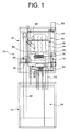
- a wall-mounted pellet boiler according to a preferred embodiment of the present invention is wholly indicated 10 and basically comprises a frame structure 12, a tank unit 14 supported by the bottom part of the frame structure 12 and a boiler body 16 supported in the top part of the frame structure 12.
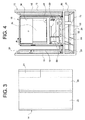
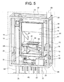
- the frame structure 12 can be observed as a whole in figure 2 and, limited to just the top part, in figures 4 and 5 and basically comprises four vertical uprights 18 and a plurality of horizontal cross members 20 that interconnect the vertical uprights 18.
- the frame structure 12 is divided into two parts, namely a bottom part that supports the tank unit 14 and a top part that supports the boiler body 16.
- a constructive choice is not in any way necessary, as the frame structure can also be made in a single piece.
- what is important for the purposes of the present invention is the arrangement of the tank unit 14 below the boiler body 16.
- the boiler and in particular the boiler body 16 to be wall-mounted, or suspended, for example in a pre-existing boiler space, to replace a gas boiler with a pellet boiler.
- the arrangement of the tank unit 14 at the bottom makes it easier to load the solid fuel (in the present case pellets) and also makes it possible to avoid risks of the solid fuel contained in the relative tank from catching fire.
- making the frame structure 12 in two distinct parts, that is a bottom part and a top part, respectively, allows greater freedom in mounting the tank unit 14 and the boiler body 16.
- the tank unit 14 is arranged in the bottom part of the boiler, as mentioned above, and basically comprises a fuel tank 22, in which the solid fuel (in the present case pellets) intended to be fed to the burner of the boiler is contained, an ash container 24, in which the combustion residue (ash) coming from the burner of the boiler is collected, and a tank 26 for sanitary hot water.
- the ash container 24 is extremely small in size, since the high efficiency of the combustion that can be obtained with the boiler according to the invention ensures that the amount of ash produced is much less than known pellet boilers. Therefore, it is possible to minimise the size of the ash container 24 without increasing the frequency with which the user of the boiler has to take care of emptying it.
- the tank 26 for hot water is advantageously received in the tank unit 14 arranged below the boiler body 16, but might also be arranged in any other position than the fuel tank 22, if necessary even above the boiler body 16.
- the tank 26 for sanitary hot water it is preferable to arrange the tank 26 for sanitary hot water inside the tank unit 14, as this contributes to containing the overall sizes of the boiler.
- the boiler 10 basically includes the following modules:
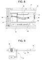
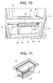
- the burner module basically comprises a crucible 30 ( figure 11 ) and an ignition device wholly indicated 32 ( figure 9 ).
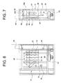
- the crucible 30 has a bottom wall 34 with a plurality of holes 36 for the comburent air that enters into the boiler body 16 through one or more openings 28 ( figures 5 to 7 ) provided in a side wall thereof.
- the ignition device 32 comprises:
- the ignition of the pellet is obtained by exploiting the heating effect of the rod by induction and the ignition effect of the pellet by direct contact with the rod.
- the ignition device according to the invention much shorter ignition times, in the order of 2 minutes at most, and much lower consumption, in the order of a few Watts, are obtained.
- the performance of the boiler in terms of response speed in this way becomes comparable to that of a common methane boiler, which is particularly important above all in view of the use of the boiler for producing sanitary hot water.
- the ignition device 32 has an associated temperature sensor T0 that by measuring the resistance in the conductors of the secondary of the transformer 38 is able to detect the temperature in the rod 40, and therefore the combustion temperature. It is thus possible to control the combustion temperature in real time and in an extremely simple manner.
- the ignition device 32 described above is clearly able to be used in a boiler operating with any other different type of solid fuel.
- the heating chamber module is arranged in a top space 44 of the boiler body 16 defined at the bottom by a horizontal plate 46 having a central opening in which the crucible 30 is inserted ( figure 11 ).
- the heating chamber module basically comprises a heat exchanger 48 having the function of transferring the heat of the fumes produced by the combustion of the pellet to the water of the heating circuit associated with the boiler.
- the heat exchanger 48 includes a body 50 that almost completely envelops the area where the combustion heat is generated and that contains the water to be heated.
- the body 50 includes a first front vertical portion 50a that closes the top half of the space 44 at the front, a second top horizontal portion 50b that closes the space 44 at the top and a third rear vertical portion 50c that closes the space 44 at the back.
- a plurality of fins 52 are provided, which have the function of increasing the heat exchange surface between the fumes produced by the combustion and the water contained in the body of the exchanger.
- the heat exchanger 48 also includes a separating plate 54 made from refractive material that separates the fins 52 from the area in which the combustion takes place and has the function of conveying the fumes against the surface of the body 50 equipped with the fins 52.
- fins 52 are depicted just on the front face of the portion 50c of the body 50 of the heat exchanger 48, fins may also be provided on the faces of the other two portions 50a and 50b of the body 50 licked by the fumes, in other words on the rear face of the portion 50a and on the bottom face of the portion 50b.
- further separating plates made from refractive material are advantageously provided, which are suitable for conveying the fumes against the further finned faces of the body of the heat exchanger.
- the fume extraction module basically includes:
- the motor fan 60 has an associated angular velocity sensor H (schematically indicated in figure 15 ), for example made as a Hall effect sensor, which provides an angular velocity signal to an electronic control unit ECU ( figure 15 ) that oversees the operation of the boiler, for feedback control of the motor fan.
- H angular velocity sensor
- ECU electronice control unit
- the ash discharging module basically includes a roller 68 suitable for fragmenting the residue of the combustion of the pellet (ash) that accumulates in the crucible 30 and conveying it towards the ash container 24 through a chute 70 and a vertical tube 72, as well as an electric motor 74 (schematically illustrated in figures 1 , 2 and 5 ) suitable for setting the roller 68 in rotation.
- a roller 68 suitable for fragmenting the residue of the combustion of the pellet (ash) that accumulates in the crucible 30 and conveying it towards the ash container 24 through a chute 70 and a vertical tube 72, as well as an electric motor 74 (schematically illustrated in figures 1 , 2 and 5 ) suitable for setting the roller 68 in rotation.
- the roller 68 comprises a cylindrical outer shell 76, preferably made from stainless steel, having a plurality of through openings or holes 78, which are made in the present case as perforated protuberances projecting in the radially outward direction so as to make a grated surface, and an auger or screw (not shown) arranged inside the shell 76.
- Both the shell 76 and the auger are set in rotation by the electric motor 74.
- the shell 76 thanks to the grated outer surface cooperating with the perforated bottom wall 34 of the crucible 30, has the function of fragmenting the combustion of the pellet, whereas the auger has the function of axially discharging such residue from the shell 76, conveying it towards the chute 70.
- the electric motor 74 is automatically controlled by the electronic control unit ECU.
- the roller 168 comprises a cylindrical outer shell 176, preferably made from stainless steel, having a plurality of through openings or slots 178, so as to allow the combustion residue (ash) to pass through, each of the through openings or slots extending along a direction inclined with respect to the axis of the shell (i.e. to the axis of rotation of the roller). Inside the shell 176 an auger or screw can be received.
- the ash discharging module described above both with reference to figures 5 and 10 , and with reference to figure 12 can be used in a boiler operating with any other different type of solid fuel.
- the fuel loading module basically includes a vertical tube 82 that extends upwards from the fuel tank 22 alongside the boiler body 16, a feeding auger (not shown) received inside the vertical tube 82 to transport the fuel (pellets) upwards from the fuel tank 22, an electric motor (also not shown) suitable for setting the feeding auger in rotation under the control of the electronic control unit ECU and an oblique tube 84 which extends downwards from a side of the vertical tube 82 opening out inside the top space 44 of the boiler body 16 and from which the fuel transported upwards by the feeding auger falls by gravity.
- the heat recovery module basically comprises a double-walled cylindrical tube 86 fitted around the flue 66 and preferably made from aluminized steel.
- the recovery water coming from the return circuit of the boiler, the recovery water entering into the tube 86 through an inlet fitting 88 and coming out from the tube 86 through an outlet fitting 90, the inlet and outlet fittings 88, 90 being arranged in the bottom part and top part, respectively, of the tube 86.
- the tube carries out both a heat recovery function (the fumes give up heat to the return water) and an anti-condensation circulation function.
- the heat recovery module also comprises a coiled tube 92 ( figure 14 ) made as a smooth tube or, alternatively, as a corrugated tube in order to increase the heat exchange surface.
- the coiled tube 92 has an inlet end 94 connected to the outlet fitting 90 of the tube 86 and an outlet end 96 coming out from the flue 66 and extends, between the two inlet and outlet ends, with a vertical coiled extension inside the flue itself, so as to allow more heat to be given up by the fumes flowing in the flue to the recovery water flowing in the coiled tube.
- the heat recovery module described above with reference to the application to the pellet boiler of figure 1 can be installed on a boiler of any other type.
- the hydraulic module is substantially of the per-se-known type and therefore will not be described in detail. In order to understand the present invention it is sufficient to highlight that it includes, in addition to the tank 26 for sanitary hot water, a circulator or pump P (schematically indicated in figure 15 ) of medium head, an automatic air bleeder valve (not shown), a safety valve or pressure limit valve (also not shown), an expansion vessel (also not shown), a water flow switch F (schematically indicated in figure 15 ), a three-way diverter valve V (schematically indicated in figure 15 ) and a series of ball shut-off valves (not shown).
- a circulator or pump P (schematically indicated in figure 15 ) of medium head, an automatic air bleeder valve (not shown), a safety valve or pressure limit valve (also not shown), an expansion vessel (also not shown), a water flow switch F (schematically indicated in figure 15 ), a three-way diverter valve V (schematically indicated in figure 15 ) and a series of ball shut-off valve
- the control module comprises, in addition to the aforementioned electronic control unit ECU, a control panel CP through which the user is able, for example, to programme the on/off time periods of the boiler, a timer thermostat TT and a plurality of per-se-known sensors, like the aforementioned temperature sensor T0 configured to measure the combustion temperature, a temperature sensor T1 configured to measure the temperature of the fuel (biomass/pellet), a temperature sensor T2 configured to measure the temperature of the fumes, a temperature sensor T3 configured to measure the temperature of the water, a temperature sensor T4 configured to measure the temperature of the structure of the boiler, as well as the aforementioned angular velocity sensor H.
- a control panel CP through which the user is able, for example, to programme the on/off time periods of the boiler
- a timer thermostat TT and a plurality of per-se-known sensors, like the aforementioned temperature sensor T0 configured to measure the combustion temperature
- a temperature sensor T1 configured to measure the temperature of the fuel
- the electronic control unit ECU receives in input measurement or threshold signals provided by the sensors T0-T4, by the water flow switch F, by the timer thermostat TT and by the angular velocity sensor H and sends in output control signals to the circulator or pump P, to the three-way diverter valve V, to the electric motor that sets the feeding auger in rotation, to the electric motor 74 that sets the roller 68 of the combustion residue discharging module in rotation, and to the motor fan 60.
- a solid fuel wall-mounted boiler according to the invention may also be made using an ignition device, an ash discharging device and/or a heat recovery device other than those described and illustrated in the present application.
Landscapes
- Engineering & Computer Science (AREA)
- Mechanical Engineering (AREA)
- General Engineering & Computer Science (AREA)
- Physics & Mathematics (AREA)
- Combustion & Propulsion (AREA)
- Chemical & Material Sciences (AREA)
- Thermal Sciences (AREA)
- Computer Hardware Design (AREA)
- Fluid Mechanics (AREA)
- Water Supply & Treatment (AREA)
- Solid-Fuel Combustion (AREA)
- General Induction Heating (AREA)
- Processing Of Solid Wastes (AREA)
Applications Claiming Priority (2)
| Application Number | Priority Date | Filing Date | Title |
|---|---|---|---|
| IT000386A ITTO20080386A1 (it) | 2008-05-23 | 2008-05-23 | Caldaia murale a pellet per il riscaldamento e la produzione di acqua calda sanitaria |
| EP09745109A EP2307804A2 (de) | 2008-05-23 | 2009-05-22 | Wandmontierter festbrennstoffkessel zum heizen von räumen und erzeugen von warmem brauchwasser |
Related Parent Applications (1)
| Application Number | Title | Priority Date | Filing Date |
|---|---|---|---|
| EP09745109.0 Division | 2009-05-22 |
Publications (1)
| Publication Number | Publication Date |
|---|---|
| EP2320145A2 true EP2320145A2 (de) | 2011-05-11 |
Family
ID=40303115
Family Applications (2)
| Application Number | Title | Priority Date | Filing Date |
|---|---|---|---|
| EP09745109A Withdrawn EP2307804A2 (de) | 2008-05-23 | 2009-05-22 | Wandmontierter festbrennstoffkessel zum heizen von räumen und erzeugen von warmem brauchwasser |
| EP11150116A Withdrawn EP2320145A2 (de) | 2008-05-23 | 2009-05-22 | Wandmontierter Festbrennstoffboiler zum Heizen von Räumen und Aufheizen von Sanitärwasser |
Family Applications Before (1)
| Application Number | Title | Priority Date | Filing Date |
|---|---|---|---|
| EP09745109A Withdrawn EP2307804A2 (de) | 2008-05-23 | 2009-05-22 | Wandmontierter festbrennstoffkessel zum heizen von räumen und erzeugen von warmem brauchwasser |
Country Status (3)
| Country | Link |
|---|---|
| EP (2) | EP2307804A2 (de) |
| IT (1) | ITTO20080386A1 (de) |
| WO (1) | WO2009141808A2 (de) |
Cited By (1)
| Publication number | Priority date | Publication date | Assignee | Title |
|---|---|---|---|---|
| EP3693663A1 (de) * | 2019-02-11 | 2020-08-12 | Haas + Sohn Ofentechnik GmbH | Pelletbrenner |
Families Citing this family (2)
| Publication number | Priority date | Publication date | Assignee | Title |
|---|---|---|---|---|
| DE102013224222A1 (de) * | 2013-03-12 | 2014-09-18 | Robert Bosch Gmbh | Heizgerät mit mindestens einer Heizeinrichtung |
| EP3775685A4 (de) * | 2018-05-07 | 2022-01-12 | Dansons, Inc. | Zündsystem für induktionsbrenner |
Family Cites Families (3)
| Publication number | Priority date | Publication date | Assignee | Title |
|---|---|---|---|---|
| BE445467A (de) * | ||||
| US4649260A (en) * | 1983-03-16 | 1987-03-10 | Coal-O-Matic Pvba | Lighter for stove, open hearth and similar |
| FR2811065A3 (fr) * | 2000-06-30 | 2002-01-04 | Bourhis Jean Erick Le | Systeme d'allumage automatique differe pour foyer fermes et insert |
-
2008
- 2008-05-23 IT IT000386A patent/ITTO20080386A1/it unknown
-
2009
- 2009-05-22 WO PCT/IB2009/052150 patent/WO2009141808A2/en not_active Ceased
- 2009-05-22 EP EP09745109A patent/EP2307804A2/de not_active Withdrawn
- 2009-05-22 EP EP11150116A patent/EP2320145A2/de not_active Withdrawn
Non-Patent Citations (1)
| Title |
|---|
| None |
Cited By (1)
| Publication number | Priority date | Publication date | Assignee | Title |
|---|---|---|---|---|
| EP3693663A1 (de) * | 2019-02-11 | 2020-08-12 | Haas + Sohn Ofentechnik GmbH | Pelletbrenner |
Also Published As
| Publication number | Publication date |
|---|---|
| WO2009141808A3 (en) | 2010-10-28 |
| WO2009141808A2 (en) | 2009-11-26 |
| EP2307804A2 (de) | 2011-04-13 |
| ITTO20080386A1 (it) | 2009-11-24 |
Similar Documents
| Publication | Publication Date | Title |
|---|---|---|
| US4371111A (en) | Home heating system employing water heater as heating source | |
| EP0854324B1 (de) | Ofen mit natürlichem Zug für Brennstoffpellets | |
| US4406402A (en) | Flue heat recovery system | |
| EP2320145A2 (de) | Wandmontierter Festbrennstoffboiler zum Heizen von Räumen und Aufheizen von Sanitärwasser | |
| US4417546A (en) | Heat recovery system for an incinerator | |
| RU2334919C1 (ru) | Водяной отопительный котел | |
| CN104913497A (zh) | 一种生物质颗粒采暖热水炉 | |
| CN106996555A (zh) | 一种全自动燃气热水蒸汽发生系统 | |
| EP2144001B1 (de) | Verfahren zur Reinigung des Rostes eines Heizgeräts | |
| CN213454015U (zh) | 一种自动添柴直热式井水太阳能综合利用空调 | |
| CN101187467A (zh) | 一种低排放高能效立置锅壳式水火管锅炉 | |
| RU100594U1 (ru) | Котел для отопления и горячего водоснабжения, теплообменник котла и буферная емкость котла | |
| SU1758349A1 (ru) | Водогрейный котел | |
| CN204730451U (zh) | 高效环保热风炉 | |
| CN217519829U (zh) | 蒸汽发生器 | |
| US347463A (en) | Steam-heating apparatus | |
| EP2674680A2 (de) | Festbrennstoffvorrichtung zum Erwärmen mit Luft, ein oder mehrere Benutzereinrichtungen und entsprechendes Erwärmungsverfahren | |
| KR100429549B1 (ko) | 석탄 보일러 | |
| KR200379084Y1 (ko) | 화목 보일러 | |
| CN213746858U (zh) | 一种环保节煤炉 | |
| CN223769046U (zh) | 一种速热烧水炉 | |
| KR101288273B1 (ko) | 다기능을 보유한 효율향상 펠릿 보일러 | |
| US5377661A (en) | Wood burning stove for heating water | |
| RU89209U1 (ru) | Водогрейный комбинированный котел | |
| RS1665U1 (sr) | Naprava za iskorišćenje toplote dimnih gasova peći na čvrsta goriva |
Legal Events
| Date | Code | Title | Description |
|---|---|---|---|
| PUAI | Public reference made under article 153(3) epc to a published international application that has entered the european phase |
Free format text: ORIGINAL CODE: 0009012 |
|
| AC | Divisional application: reference to earlier application |
Ref document number: 2307804 Country of ref document: EP Kind code of ref document: P |
|
| AK | Designated contracting states |
Kind code of ref document: A2 Designated state(s): AT BE BG CH CY CZ DE DK EE ES FI FR GB GR HR HU IE IS IT LI LT LU LV MC MK MT NL NO PL PT RO SE SI SK TR |
|
| AX | Request for extension of the european patent |
Extension state: AL BA RS |
|
| STAA | Information on the status of an ep patent application or granted ep patent |
Free format text: STATUS: THE APPLICATION IS DEEMED TO BE WITHDRAWN |
|
| 18D | Application deemed to be withdrawn |
Effective date: 20151201 |