EP2320145A2 - Solid fuel wall-mounted boiler for heating rooms and producing sanitary hot water - Google Patents
Solid fuel wall-mounted boiler for heating rooms and producing sanitary hot water Download PDFInfo
- Publication number
- EP2320145A2 EP2320145A2 EP11150116A EP11150116A EP2320145A2 EP 2320145 A2 EP2320145 A2 EP 2320145A2 EP 11150116 A EP11150116 A EP 11150116A EP 11150116 A EP11150116 A EP 11150116A EP 2320145 A2 EP2320145 A2 EP 2320145A2
- Authority
- EP
- European Patent Office
- Prior art keywords
- boiler
- boiler according
- combustion
- module
- solid fuel
- Prior art date
- Legal status (The legal status is an assumption and is not a legal conclusion. Google has not performed a legal analysis and makes no representation as to the accuracy of the status listed.)
- Withdrawn
Links
- XLYOFNOQVPJJNP-UHFFFAOYSA-N water Substances O XLYOFNOQVPJJNP-UHFFFAOYSA-N 0.000 title claims abstract description 33
- 238000010438 heat treatment Methods 0.000 title claims abstract description 16
- 239000004449 solid propellant Substances 0.000 title claims description 25
- 238000002485 combustion reaction Methods 0.000 claims abstract description 29
- 238000011084 recovery Methods 0.000 claims abstract description 18
- 238000007599 discharging Methods 0.000 claims abstract description 12
- 239000002828 fuel tank Substances 0.000 claims abstract description 8
- 230000006698 induction Effects 0.000 claims abstract description 3
- 239000007769 metal material Substances 0.000 claims abstract description 3
- 239000003517 fume Substances 0.000 claims description 21
- 239000002028 Biomass Substances 0.000 claims description 13
- 239000000446 fuel Substances 0.000 claims description 7
- 239000004020 conductor Substances 0.000 claims description 3
- 238000000605 extraction Methods 0.000 claims description 3
- 239000012634 fragment Substances 0.000 claims 1
- 239000008188 pellet Substances 0.000 description 26
- 239000007789 gas Substances 0.000 description 6
- 230000000694 effects Effects 0.000 description 4
- 238000010586 diagram Methods 0.000 description 2
- 238000009434 installation Methods 0.000 description 2
- 239000000463 material Substances 0.000 description 2
- VNWKTOKETHGBQD-UHFFFAOYSA-N methane Chemical compound C VNWKTOKETHGBQD-UHFFFAOYSA-N 0.000 description 2
- 239000010935 stainless steel Substances 0.000 description 2
- 229910001220 stainless steel Inorganic materials 0.000 description 2
- 229910000680 Aluminized steel Inorganic materials 0.000 description 1
- 230000005355 Hall effect Effects 0.000 description 1
- 238000009833 condensation Methods 0.000 description 1
- 239000013256 coordination polymer Substances 0.000 description 1
- 230000001419 dependent effect Effects 0.000 description 1
- 238000005265 energy consumption Methods 0.000 description 1
- 230000005484 gravity Effects 0.000 description 1
- 238000012423 maintenance Methods 0.000 description 1
- 238000004519 manufacturing process Methods 0.000 description 1
- 238000005259 measurement Methods 0.000 description 1
- 229910001092 metal group alloy Inorganic materials 0.000 description 1
Images


Classifications
-
- F—MECHANICAL ENGINEERING; LIGHTING; HEATING; WEAPONS; BLASTING
- F23—COMBUSTION APPARATUS; COMBUSTION PROCESSES
- F23B—METHODS OR APPARATUS FOR COMBUSTION USING ONLY SOLID FUEL
- F23B40/00—Combustion apparatus with driven means for feeding fuel into the combustion chamber
- F23B40/06—Combustion apparatus with driven means for feeding fuel into the combustion chamber the fuel being fed along the fuel-supporting surface
- F23B40/08—Combustion apparatus with driven means for feeding fuel into the combustion chamber the fuel being fed along the fuel-supporting surface into pot- or trough-shaped grates
-
- F—MECHANICAL ENGINEERING; LIGHTING; HEATING; WEAPONS; BLASTING
- F23—COMBUSTION APPARATUS; COMBUSTION PROCESSES
- F23J—REMOVAL OR TREATMENT OF COMBUSTION PRODUCTS OR COMBUSTION RESIDUES; FLUES
- F23J1/00—Removing ash, clinker, or slag from combustion chambers
- F23J1/06—Mechanically-operated devices, e.g. clinker pushers
-
- F—MECHANICAL ENGINEERING; LIGHTING; HEATING; WEAPONS; BLASTING
- F24—HEATING; RANGES; VENTILATING
- F24C—DOMESTIC STOVES OR RANGES ; DETAILS OF DOMESTIC STOVES OR RANGES, OF GENERAL APPLICATION
- F24C13/00—Stoves or ranges with additional provisions for heating water
-
- F—MECHANICAL ENGINEERING; LIGHTING; HEATING; WEAPONS; BLASTING
- F24—HEATING; RANGES; VENTILATING
- F24D—DOMESTIC- OR SPACE-HEATING SYSTEMS, e.g. CENTRAL HEATING SYSTEMS; DOMESTIC HOT-WATER SUPPLY SYSTEMS; ELEMENTS OR COMPONENTS THEREFOR
- F24D3/00—Hot-water central heating systems
- F24D3/08—Hot-water central heating systems in combination with systems for domestic hot-water supply
-
- F—MECHANICAL ENGINEERING; LIGHTING; HEATING; WEAPONS; BLASTING
- F24—HEATING; RANGES; VENTILATING
- F24H—FLUID HEATERS, e.g. WATER OR AIR HEATERS, HAVING HEAT-GENERATING MEANS, e.g. HEAT PUMPS, IN GENERAL
- F24H1/00—Water heaters, e.g. boilers, continuous-flow heaters or water-storage heaters
- F24H1/22—Water heaters other than continuous-flow or water-storage heaters, e.g. water heaters for central heating
- F24H1/40—Water heaters other than continuous-flow or water-storage heaters, e.g. water heaters for central heating with water tube or tubes
-
- F—MECHANICAL ENGINEERING; LIGHTING; HEATING; WEAPONS; BLASTING
- F24—HEATING; RANGES; VENTILATING
- F24H—FLUID HEATERS, e.g. WATER OR AIR HEATERS, HAVING HEAT-GENERATING MEANS, e.g. HEAT PUMPS, IN GENERAL
- F24H15/00—Control of fluid heaters
- F24H15/20—Control of fluid heaters characterised by control inputs
- F24H15/212—Temperature of the water
-
- F—MECHANICAL ENGINEERING; LIGHTING; HEATING; WEAPONS; BLASTING
- F24—HEATING; RANGES; VENTILATING
- F24H—FLUID HEATERS, e.g. WATER OR AIR HEATERS, HAVING HEAT-GENERATING MEANS, e.g. HEAT PUMPS, IN GENERAL
- F24H15/00—Control of fluid heaters
- F24H15/20—Control of fluid heaters characterised by control inputs
- F24H15/238—Flow rate
-
- F—MECHANICAL ENGINEERING; LIGHTING; HEATING; WEAPONS; BLASTING
- F24—HEATING; RANGES; VENTILATING
- F24H—FLUID HEATERS, e.g. WATER OR AIR HEATERS, HAVING HEAT-GENERATING MEANS, e.g. HEAT PUMPS, IN GENERAL
- F24H15/00—Control of fluid heaters
- F24H15/20—Control of fluid heaters characterised by control inputs
- F24H15/25—Temperature of the heat-generating means in the heater
-
- F—MECHANICAL ENGINEERING; LIGHTING; HEATING; WEAPONS; BLASTING
- F24—HEATING; RANGES; VENTILATING
- F24H—FLUID HEATERS, e.g. WATER OR AIR HEATERS, HAVING HEAT-GENERATING MEANS, e.g. HEAT PUMPS, IN GENERAL
- F24H15/00—Control of fluid heaters
- F24H15/30—Control of fluid heaters characterised by control outputs; characterised by the components to be controlled
- F24H15/305—Control of valves
- F24H15/32—Control of valves of switching valves
-
- F—MECHANICAL ENGINEERING; LIGHTING; HEATING; WEAPONS; BLASTING
- F24—HEATING; RANGES; VENTILATING
- F24H—FLUID HEATERS, e.g. WATER OR AIR HEATERS, HAVING HEAT-GENERATING MEANS, e.g. HEAT PUMPS, IN GENERAL
- F24H15/00—Control of fluid heaters
- F24H15/30—Control of fluid heaters characterised by control outputs; characterised by the components to be controlled
- F24H15/335—Control of pumps, e.g. on-off control
-
- F—MECHANICAL ENGINEERING; LIGHTING; HEATING; WEAPONS; BLASTING
- F24—HEATING; RANGES; VENTILATING
- F24H—FLUID HEATERS, e.g. WATER OR AIR HEATERS, HAVING HEAT-GENERATING MEANS, e.g. HEAT PUMPS, IN GENERAL
- F24H15/00—Control of fluid heaters
- F24H15/30—Control of fluid heaters characterised by control outputs; characterised by the components to be controlled
- F24H15/345—Control of fans, e.g. on-off control
- F24H15/35—Control of the speed of fans
-
- F—MECHANICAL ENGINEERING; LIGHTING; HEATING; WEAPONS; BLASTING
- F24—HEATING; RANGES; VENTILATING
- F24H—FLUID HEATERS, e.g. WATER OR AIR HEATERS, HAVING HEAT-GENERATING MEANS, e.g. HEAT PUMPS, IN GENERAL
- F24H15/00—Control of fluid heaters
- F24H15/30—Control of fluid heaters characterised by control outputs; characterised by the components to be controlled
- F24H15/355—Control of heat-generating means in heaters
- F24H15/36—Control of heat-generating means in heaters of burners
-
- F—MECHANICAL ENGINEERING; LIGHTING; HEATING; WEAPONS; BLASTING
- F24—HEATING; RANGES; VENTILATING
- F24H—FLUID HEATERS, e.g. WATER OR AIR HEATERS, HAVING HEAT-GENERATING MEANS, e.g. HEAT PUMPS, IN GENERAL
- F24H15/00—Control of fluid heaters
- F24H15/40—Control of fluid heaters characterised by the type of controllers
- F24H15/414—Control of fluid heaters characterised by the type of controllers using electronic processing, e.g. computer-based
-
- F—MECHANICAL ENGINEERING; LIGHTING; HEATING; WEAPONS; BLASTING
- F24—HEATING; RANGES; VENTILATING
- F24H—FLUID HEATERS, e.g. WATER OR AIR HEATERS, HAVING HEAT-GENERATING MEANS, e.g. HEAT PUMPS, IN GENERAL
- F24H9/00—Details
- F24H9/02—Casings; Cover lids; Ornamental panels
-
- F—MECHANICAL ENGINEERING; LIGHTING; HEATING; WEAPONS; BLASTING
- F24—HEATING; RANGES; VENTILATING
- F24H—FLUID HEATERS, e.g. WATER OR AIR HEATERS, HAVING HEAT-GENERATING MEANS, e.g. HEAT PUMPS, IN GENERAL
- F24H9/00—Details
- F24H9/06—Arrangement of mountings or supports for heaters, e.g. boilers, other than space heating radiators
-
- F—MECHANICAL ENGINEERING; LIGHTING; HEATING; WEAPONS; BLASTING
- F24—HEATING; RANGES; VENTILATING
- F24H—FLUID HEATERS, e.g. WATER OR AIR HEATERS, HAVING HEAT-GENERATING MEANS, e.g. HEAT PUMPS, IN GENERAL
- F24H9/00—Details
- F24H9/20—Arrangement or mounting of control or safety devices
- F24H9/2007—Arrangement or mounting of control or safety devices for water heaters
- F24H9/2057—Arrangement or mounting of control or safety devices for water heaters using solid fuel
-
- F—MECHANICAL ENGINEERING; LIGHTING; HEATING; WEAPONS; BLASTING
- F24—HEATING; RANGES; VENTILATING
- F24H—FLUID HEATERS, e.g. WATER OR AIR HEATERS, HAVING HEAT-GENERATING MEANS, e.g. HEAT PUMPS, IN GENERAL
- F24H9/00—Details
- F24H9/20—Arrangement or mounting of control or safety devices
- F24H9/25—Arrangement or mounting of control or safety devices of remote control devices or control-panels
-
- F—MECHANICAL ENGINEERING; LIGHTING; HEATING; WEAPONS; BLASTING
- F23—COMBUSTION APPARATUS; COMBUSTION PROCESSES
- F23J—REMOVAL OR TREATMENT OF COMBUSTION PRODUCTS OR COMBUSTION RESIDUES; FLUES
- F23J2900/00—Special arrangements for conducting or purifying combustion fumes; Treatment of fumes or ashes
- F23J2900/01003—Ash crushing means associated with ash removal means
-
- F—MECHANICAL ENGINEERING; LIGHTING; HEATING; WEAPONS; BLASTING
- F23—COMBUSTION APPARATUS; COMBUSTION PROCESSES
- F23N—REGULATING OR CONTROLLING COMBUSTION
- F23N2227/00—Ignition or checking
- F23N2227/38—Electrical resistance ignition
-
- F—MECHANICAL ENGINEERING; LIGHTING; HEATING; WEAPONS; BLASTING
- F23—COMBUSTION APPARATUS; COMBUSTION PROCESSES
- F23N—REGULATING OR CONTROLLING COMBUSTION
- F23N2233/00—Ventilators
- F23N2233/02—Ventilators in stacks
-
- F—MECHANICAL ENGINEERING; LIGHTING; HEATING; WEAPONS; BLASTING
- F24—HEATING; RANGES; VENTILATING
- F24H—FLUID HEATERS, e.g. WATER OR AIR HEATERS, HAVING HEAT-GENERATING MEANS, e.g. HEAT PUMPS, IN GENERAL
- F24H15/00—Control of fluid heaters
- F24H15/40—Control of fluid heaters characterised by the type of controllers
- F24H15/486—Control of fluid heaters characterised by the type of controllers using timers
-
- F—MECHANICAL ENGINEERING; LIGHTING; HEATING; WEAPONS; BLASTING
- F24—HEATING; RANGES; VENTILATING
- F24H—FLUID HEATERS, e.g. WATER OR AIR HEATERS, HAVING HEAT-GENERATING MEANS, e.g. HEAT PUMPS, IN GENERAL
- F24H2230/00—Solid fuel fired boiler
Definitions
- the present invention concerns a solid fuel wall-mounted boiler, in particular a biomass wall-mounted boiler (for example a pellet boiler), able to be used for heating rooms, be they for civil or industrial use, as well as for producing sanitary hot water.
- a biomass wall-mounted boiler for example a pellet boiler
- the ignition of the combustion is obtained by feeding current to an electric resistance arranged behind a combustion chamber in which the biomass (pellets) is loaded.
- the electric resistance made incandescent by Joule effect, heats the air at room temperature fed from outside into the combustion chamber. The flow of air thus heated hits the biomass contained in the combustion chamber and sets it alight.
- Such a known ignition system on the one hand requires long ignition times, which vary on average between 15 and 20 minutes and are therefore incompatible with use of the boiler to produce sanitary hot water, and on the other hand involves high electrical energy consumption, since the power involved is in the order of 200 ⁇ 300 W.
- a further drawback of current solid fuel boilers, and in particular of biomass (pellet) boilers, able to be used both for heating rooms and for producing sanitary hot water, is represented by the considerable overall sizes and therefore by the fact that it is impossible to position the boiler in common boiler spaces provided in civil dwellings, in particular in the case of boiler spaces located inside apartments and/or relative balconies. Therefore, it is not possible to consider, in an apartment already set up for the installation of a gas boiler or already equipped with a gas boiler for heating and for producing sanitary hot water, replacing the gas boiler with a solid fuel boiler, in particular a biomass (pellet) boiler, currently produced. Indeed, it would be necessary either to provide a special boiler room able to receive the new boiler or to arrange the new boiler on the floor inside the apartment itself. Both of these solutions are, however, clearly not very convenient.
- biomass boilers such as pellet boilers
- a wall-mounted pellet boiler according to a preferred embodiment of the present invention is wholly indicated 10 and basically comprises a frame structure 12, a tank unit 14 supported by the bottom part of the frame structure 12 and a boiler body 16 supported in the top part of the frame structure 12.
- the frame structure 12 can be observed as a whole in figure 2 and, limited to just the top part, in figures 4 and 5 and basically comprises four vertical uprights 18 and a plurality of horizontal cross members 20 that interconnect the vertical uprights 18.
- the frame structure 12 is divided into two parts, namely a bottom part that supports the tank unit 14 and a top part that supports the boiler body 16.
- a constructive choice is not in any way necessary, as the frame structure can also be made in a single piece.
- what is important for the purposes of the present invention is the arrangement of the tank unit 14 below the boiler body 16.
- the boiler and in particular the boiler body 16 to be wall-mounted, or suspended, for example in a pre-existing boiler space, to replace a gas boiler with a pellet boiler.
- the arrangement of the tank unit 14 at the bottom makes it easier to load the solid fuel (in the present case pellets) and also makes it possible to avoid risks of the solid fuel contained in the relative tank from catching fire.
- making the frame structure 12 in two distinct parts, that is a bottom part and a top part, respectively, allows greater freedom in mounting the tank unit 14 and the boiler body 16.
- the tank unit 14 is arranged in the bottom part of the boiler, as mentioned above, and basically comprises a fuel tank 22, in which the solid fuel (in the present case pellets) intended to be fed to the burner of the boiler is contained, an ash container 24, in which the combustion residue (ash) coming from the burner of the boiler is collected, and a tank 26 for sanitary hot water.
- the ash container 24 is extremely small in size, since the high efficiency of the combustion that can be obtained with the boiler according to the invention ensures that the amount of ash produced is much less than known pellet boilers. Therefore, it is possible to minimise the size of the ash container 24 without increasing the frequency with which the user of the boiler has to take care of emptying it.
- the tank 26 for hot water is advantageously received in the tank unit 14 arranged below the boiler body 16, but might also be arranged in any other position than the fuel tank 22, if necessary even above the boiler body 16.
- the tank 26 for sanitary hot water it is preferable to arrange the tank 26 for sanitary hot water inside the tank unit 14, as this contributes to containing the overall sizes of the boiler.
- the boiler 10 basically includes the following modules:
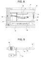
- the burner module basically comprises a crucible 30 ( figure 11 ) and an ignition device wholly indicated 32 ( figure 9 ).
- the crucible 30 has a bottom wall 34 with a plurality of holes 36 for the comburent air that enters into the boiler body 16 through one or more openings 28 ( figures 5 to 7 ) provided in a side wall thereof.
- the ignition device 32 comprises:
- the ignition of the pellet is obtained by exploiting the heating effect of the rod by induction and the ignition effect of the pellet by direct contact with the rod.
- the ignition device according to the invention much shorter ignition times, in the order of 2 minutes at most, and much lower consumption, in the order of a few Watts, are obtained.
- the performance of the boiler in terms of response speed in this way becomes comparable to that of a common methane boiler, which is particularly important above all in view of the use of the boiler for producing sanitary hot water.
- the ignition device 32 has an associated temperature sensor T0 that by measuring the resistance in the conductors of the secondary of the transformer 38 is able to detect the temperature in the rod 40, and therefore the combustion temperature. It is thus possible to control the combustion temperature in real time and in an extremely simple manner.
- the ignition device 32 described above is clearly able to be used in a boiler operating with any other different type of solid fuel.
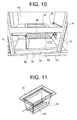
- the heating chamber module is arranged in a top space 44 of the boiler body 16 defined at the bottom by a horizontal plate 46 having a central opening in which the crucible 30 is inserted ( figure 11 ).
- the heating chamber module basically comprises a heat exchanger 48 having the function of transferring the heat of the fumes produced by the combustion of the pellet to the water of the heating circuit associated with the boiler.
- the heat exchanger 48 includes a body 50 that almost completely envelops the area where the combustion heat is generated and that contains the water to be heated.
- the body 50 includes a first front vertical portion 50a that closes the top half of the space 44 at the front, a second top horizontal portion 50b that closes the space 44 at the top and a third rear vertical portion 50c that closes the space 44 at the back.
- a plurality of fins 52 are provided, which have the function of increasing the heat exchange surface between the fumes produced by the combustion and the water contained in the body of the exchanger.
- the heat exchanger 48 also includes a separating plate 54 made from refractive material that separates the fins 52 from the area in which the combustion takes place and has the function of conveying the fumes against the surface of the body 50 equipped with the fins 52.
- fins 52 are depicted just on the front face of the portion 50c of the body 50 of the heat exchanger 48, fins may also be provided on the faces of the other two portions 50a and 50b of the body 50 licked by the fumes, in other words on the rear face of the portion 50a and on the bottom face of the portion 50b.
- further separating plates made from refractive material are advantageously provided, which are suitable for conveying the fumes against the further finned faces of the body of the heat exchanger.
- the fume extraction module basically includes:
- the motor fan 60 has an associated angular velocity sensor H (schematically indicated in figure 15 ), for example made as a Hall effect sensor, which provides an angular velocity signal to an electronic control unit ECU ( figure 15 ) that oversees the operation of the boiler, for feedback control of the motor fan.
- H angular velocity sensor
- ECU electronice control unit
- the ash discharging module basically includes a roller 68 suitable for fragmenting the residue of the combustion of the pellet (ash) that accumulates in the crucible 30 and conveying it towards the ash container 24 through a chute 70 and a vertical tube 72, as well as an electric motor 74 (schematically illustrated in figures 1 , 2 and 5 ) suitable for setting the roller 68 in rotation.
- a roller 68 suitable for fragmenting the residue of the combustion of the pellet (ash) that accumulates in the crucible 30 and conveying it towards the ash container 24 through a chute 70 and a vertical tube 72, as well as an electric motor 74 (schematically illustrated in figures 1 , 2 and 5 ) suitable for setting the roller 68 in rotation.
- the roller 68 comprises a cylindrical outer shell 76, preferably made from stainless steel, having a plurality of through openings or holes 78, which are made in the present case as perforated protuberances projecting in the radially outward direction so as to make a grated surface, and an auger or screw (not shown) arranged inside the shell 76.
- Both the shell 76 and the auger are set in rotation by the electric motor 74.
- the shell 76 thanks to the grated outer surface cooperating with the perforated bottom wall 34 of the crucible 30, has the function of fragmenting the combustion of the pellet, whereas the auger has the function of axially discharging such residue from the shell 76, conveying it towards the chute 70.
- the electric motor 74 is automatically controlled by the electronic control unit ECU.
- the roller 168 comprises a cylindrical outer shell 176, preferably made from stainless steel, having a plurality of through openings or slots 178, so as to allow the combustion residue (ash) to pass through, each of the through openings or slots extending along a direction inclined with respect to the axis of the shell (i.e. to the axis of rotation of the roller). Inside the shell 176 an auger or screw can be received.
- the ash discharging module described above both with reference to figures 5 and 10 , and with reference to figure 12 can be used in a boiler operating with any other different type of solid fuel.
- the fuel loading module basically includes a vertical tube 82 that extends upwards from the fuel tank 22 alongside the boiler body 16, a feeding auger (not shown) received inside the vertical tube 82 to transport the fuel (pellets) upwards from the fuel tank 22, an electric motor (also not shown) suitable for setting the feeding auger in rotation under the control of the electronic control unit ECU and an oblique tube 84 which extends downwards from a side of the vertical tube 82 opening out inside the top space 44 of the boiler body 16 and from which the fuel transported upwards by the feeding auger falls by gravity.
- the heat recovery module basically comprises a double-walled cylindrical tube 86 fitted around the flue 66 and preferably made from aluminized steel.
- the recovery water coming from the return circuit of the boiler, the recovery water entering into the tube 86 through an inlet fitting 88 and coming out from the tube 86 through an outlet fitting 90, the inlet and outlet fittings 88, 90 being arranged in the bottom part and top part, respectively, of the tube 86.
- the tube carries out both a heat recovery function (the fumes give up heat to the return water) and an anti-condensation circulation function.
- the heat recovery module also comprises a coiled tube 92 ( figure 14 ) made as a smooth tube or, alternatively, as a corrugated tube in order to increase the heat exchange surface.
- the coiled tube 92 has an inlet end 94 connected to the outlet fitting 90 of the tube 86 and an outlet end 96 coming out from the flue 66 and extends, between the two inlet and outlet ends, with a vertical coiled extension inside the flue itself, so as to allow more heat to be given up by the fumes flowing in the flue to the recovery water flowing in the coiled tube.
- the heat recovery module described above with reference to the application to the pellet boiler of figure 1 can be installed on a boiler of any other type.
- the hydraulic module is substantially of the per-se-known type and therefore will not be described in detail. In order to understand the present invention it is sufficient to highlight that it includes, in addition to the tank 26 for sanitary hot water, a circulator or pump P (schematically indicated in figure 15 ) of medium head, an automatic air bleeder valve (not shown), a safety valve or pressure limit valve (also not shown), an expansion vessel (also not shown), a water flow switch F (schematically indicated in figure 15 ), a three-way diverter valve V (schematically indicated in figure 15 ) and a series of ball shut-off valves (not shown).
- a circulator or pump P (schematically indicated in figure 15 ) of medium head, an automatic air bleeder valve (not shown), a safety valve or pressure limit valve (also not shown), an expansion vessel (also not shown), a water flow switch F (schematically indicated in figure 15 ), a three-way diverter valve V (schematically indicated in figure 15 ) and a series of ball shut-off valve
- the control module comprises, in addition to the aforementioned electronic control unit ECU, a control panel CP through which the user is able, for example, to programme the on/off time periods of the boiler, a timer thermostat TT and a plurality of per-se-known sensors, like the aforementioned temperature sensor T0 configured to measure the combustion temperature, a temperature sensor T1 configured to measure the temperature of the fuel (biomass/pellet), a temperature sensor T2 configured to measure the temperature of the fumes, a temperature sensor T3 configured to measure the temperature of the water, a temperature sensor T4 configured to measure the temperature of the structure of the boiler, as well as the aforementioned angular velocity sensor H.
- a control panel CP through which the user is able, for example, to programme the on/off time periods of the boiler
- a timer thermostat TT and a plurality of per-se-known sensors, like the aforementioned temperature sensor T0 configured to measure the combustion temperature
- a temperature sensor T1 configured to measure the temperature of the fuel
- the electronic control unit ECU receives in input measurement or threshold signals provided by the sensors T0-T4, by the water flow switch F, by the timer thermostat TT and by the angular velocity sensor H and sends in output control signals to the circulator or pump P, to the three-way diverter valve V, to the electric motor that sets the feeding auger in rotation, to the electric motor 74 that sets the roller 68 of the combustion residue discharging module in rotation, and to the motor fan 60.
- a solid fuel wall-mounted boiler according to the invention may also be made using an ignition device, an ash discharging device and/or a heat recovery device other than those described and illustrated in the present application.
Abstract
Description
- The present invention concerns a solid fuel wall-mounted boiler, in particular a biomass wall-mounted boiler (for example a pellet boiler), able to be used for heating rooms, be they for civil or industrial use, as well as for producing sanitary hot water.
- The main limitation in general of solid fuel boilers, and in particular of pellet boilers, currently on the market, is represented by the ignition system. In current biomass boilers, indeed, and in particular in current pellet boilers, the ignition of the combustion is obtained by feeding current to an electric resistance arranged behind a combustion chamber in which the biomass (pellets) is loaded. The electric resistance, made incandescent by Joule effect, heats the air at room temperature fed from outside into the combustion chamber. The flow of air thus heated hits the biomass contained in the combustion chamber and sets it alight. Such a known ignition system on the one hand requires long ignition times, which vary on average between 15 and 20 minutes and are therefore incompatible with use of the boiler to produce sanitary hot water, and on the other hand involves high electrical energy consumption, since the power involved is in the order of 200÷300 W.
- A further drawback of current solid fuel boilers, and in particular of biomass (pellet) boilers, able to be used both for heating rooms and for producing sanitary hot water, is represented by the considerable overall sizes and therefore by the fact that it is impossible to position the boiler in common boiler spaces provided in civil dwellings, in particular in the case of boiler spaces located inside apartments and/or relative balconies. Therefore, it is not possible to consider, in an apartment already set up for the installation of a gas boiler or already equipped with a gas boiler for heating and for producing sanitary hot water, replacing the gas boiler with a solid fuel boiler, in particular a biomass (pellet) boiler, currently produced. Indeed, it would be necessary either to provide a special boiler room able to receive the new boiler or to arrange the new boiler on the floor inside the apartment itself. Both of these solutions are, however, clearly not very convenient.
- Other drawbacks of current solid fuel boilers, and in particular of biomass (pellet) boilers, compared to gas boilers are represented by the need to continually load the fuel tank (generally many times per week) and empty the ash container (also generally many times per week). Moreover, in current solid fuel boilers, and in particular in current biomass (pellet) boilers, the fuel tank is arranged above the burner and therefore the loading of fuel is carried out from above. However, this makes the wall-mounted, i.e. suspended, solution for such boilers impossible, forcing them to be arranged on the floor.
- It is an object of the present invention to overcome the aforementioned drawbacks of the prior art, allowing solid fuel boilers, and in particular biomass boilers (such as pellet boilers), for heating and for producing sanitary hot water to be easily and inexpensively installed inside buildings for civil or industrial use, even in case they are already set up for the installation of or are already equipped with gas systems for heating and for producing sanitary hot water, and allowing such boilers to be used with limited management and maintenance costs and interventions and with high performance levels.
- This and other objects are fully achieved according to the present invention thanks to a solid fuel boiler, in particular a biomass boiler, having the characteristics specified in the attached independent claim 1.
- Advantageous embodiments of the solid fuel boiler according to the invention form the subject-matter of the dependent claims, the content of which is to be taken as an integral and integrating part of the following description.
- The characteristics and advantages of the present invention shall become apparent from the following detailed description, given purely by way of non-limiting example with reference to the attached drawings, in which:
-
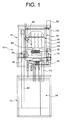
figure 1 is a schematic illustration in front view, partially in phantom, of a solid fuel wall-mounted boiler, in particular a pellet boiler, according to a preferred embodiment of the present invention; -
figure 2 is a perspective view of the boiler offigure 1 , in which some parts have been removed for the sake of easier understanding; -
figure 3 is a front view of the tank unit of the boiler offigure 1 ; -
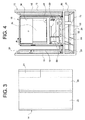
figures 4 and5 are perspective views, taken from two different angles, of the top part of the boiler offigure 1 ; -
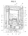
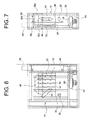
figures 6 and 7 are schematic illustrations, in perspective view and in side view, respectively, of the body of the boiler offigure 1 ; -
figure 8 is a front view of the ignition device of the boiler offigure 1 ; -
figure 9 is a circuit diagram of the ignition device of the boiler offigure 1 ; -
figure 10 is a front view of the ash discharging module of the boiler offigure 1 ; -
figure 11 is an axonometric view of a crucible forming part of the burner and cooperating with the ash discharging module offigure 10 ; -
figure 12 is an axonometric view of the roller of a variant of an ash discharging module for use in a solid fuel boiler, in particular in a pellet boiler, according to the present invention; -
figure 13 is a perspective view of the heat recovery module of the boiler offigure 1 ; -
figure 14 is an enlarged perspective view of the coiled tube of the heat recovery module offigure 13 ; and -
figure 15 is a schematic diagram of the electronic control system of the boiler offigure 1 . - The following description shall be provided with particular reference to the case of a pellet boiler, but it is clear that the invention is equally applicable to a boiler fed with any other type of solid fuel, in particular solid fuel deriving from biomass.
- With reference to the figures, a wall-mounted pellet boiler according to a preferred embodiment of the present invention is wholly indicated 10 and basically comprises a
frame structure 12, atank unit 14 supported by the bottom part of theframe structure 12 and aboiler body 16 supported in the top part of theframe structure 12. - The
frame structure 12 can be observed as a whole infigure 2 and, limited to just the top part, infigures 4 and5 and basically comprises fourvertical uprights 18 and a plurality ofhorizontal cross members 20 that interconnect thevertical uprights 18. As can be worked out fromfigure 2 , in the illustrated embodiment theframe structure 12 is divided into two parts, namely a bottom part that supports thetank unit 14 and a top part that supports theboiler body 16. However, such a constructive choice is not in any way necessary, as the frame structure can also be made in a single piece. In any case, what is important for the purposes of the present invention is the arrangement of thetank unit 14 below theboiler body 16. This allows on the one hand the boiler, and in particular theboiler body 16, to be wall-mounted, or suspended, for example in a pre-existing boiler space, to replace a gas boiler with a pellet boiler. On the other hand, the arrangement of thetank unit 14 at the bottom makes it easier to load the solid fuel (in the present case pellets) and also makes it possible to avoid risks of the solid fuel contained in the relative tank from catching fire. Moreover, making theframe structure 12 in two distinct parts, that is a bottom part and a top part, respectively, allows greater freedom in mounting thetank unit 14 and theboiler body 16. - With reference in particular to
figure 3 , thetank unit 14 is arranged in the bottom part of the boiler, as mentioned above, and basically comprises afuel tank 22, in which the solid fuel (in the present case pellets) intended to be fed to the burner of the boiler is contained, anash container 24, in which the combustion residue (ash) coming from the burner of the boiler is collected, and atank 26 for sanitary hot water. As can be clearly seen fromfigure 3 , theash container 24 is extremely small in size, since the high efficiency of the combustion that can be obtained with the boiler according to the invention ensures that the amount of ash produced is much less than known pellet boilers. Therefore, it is possible to minimise the size of theash container 24 without increasing the frequency with which the user of the boiler has to take care of emptying it. Thetank 26 for hot water is advantageously received in thetank unit 14 arranged below theboiler body 16, but might also be arranged in any other position than thefuel tank 22, if necessary even above theboiler body 16. In any case, as the small size of theash container 24 allows thetank 26 for sanitary hot water to be received also in the bottom part of the boiler, it is preferable to arrange thetank 26 for sanitary hot water inside thetank unit 14, as this contributes to containing the overall sizes of the boiler. - The
boiler 10 basically includes the following modules: - burner module;
- heating chamber module;
- fume extraction module;
- ash discharging module;
- fuel loading module;
- heat recovery module;
- hydraulic module; and
- control module.
- The burner module basically comprises a crucible 30 (
figure 11 ) and an ignition device wholly indicated 32 (figure 9 ). Thecrucible 30 has abottom wall 34 with a plurality ofholes 36 for the comburent air that enters into theboiler body 16 through one or more openings 28 (figures 5 to 7 ) provided in a side wall thereof. With reference in particular tofigure 9 , theignition device 32 comprises: - a
transformer 38, with a primary at mains voltage (220 V in the case of the domestic mains or 380 V in the case of the industrial mains) and a low-voltage secondary (preferably from 2 to 5 V), - a
rod 40 of metallic material (metallic alloy), running in a straight line or suitably shaped according to requirements, arranged in thecrucible 30 in direct contact with the pellet (figure 8 shows therod 40 outside thecrucible 30 solely for the sake of ease of representation), and - a pair of
conductors 42 that connect the secondary of thetransformer 38 to therod 40. - The ignition of the pellet is obtained by exploiting the heating effect of the rod by induction and the ignition effect of the pellet by direct contact with the rod. Compared to common ignition devices that exploit the heating of a resistance by Joule effect, with the ignition device according to the invention much shorter ignition times, in the order of 2 minutes at most, and much lower consumption, in the order of a few Watts, are obtained. The performance of the boiler in terms of response speed in this way becomes comparable to that of a common methane boiler, which is particularly important above all in view of the use of the boiler for producing sanitary hot water.
- The
ignition device 32 has an associated temperature sensor T0 that by measuring the resistance in the conductors of the secondary of thetransformer 38 is able to detect the temperature in therod 40, and therefore the combustion temperature. It is thus possible to control the combustion temperature in real time and in an extremely simple manner. - The
ignition device 32 described above is clearly able to be used in a boiler operating with any other different type of solid fuel. - The heating chamber module is arranged in a
top space 44 of theboiler body 16 defined at the bottom by ahorizontal plate 46 having a central opening in which thecrucible 30 is inserted (figure 11 ). The heating chamber module basically comprises aheat exchanger 48 having the function of transferring the heat of the fumes produced by the combustion of the pellet to the water of the heating circuit associated with the boiler. With reference in particular tofigures 4 to 7 , theheat exchanger 48 includes abody 50 that almost completely envelops the area where the combustion heat is generated and that contains the water to be heated. Thebody 50 includes a first frontvertical portion 50a that closes the top half of thespace 44 at the front, a second tophorizontal portion 50b that closes thespace 44 at the top and a third rearvertical portion 50c that closes thespace 44 at the back. On the front face of theportion 50c of thebody 50 of the heat exchanger 48 a plurality offins 52 are provided, which have the function of increasing the heat exchange surface between the fumes produced by the combustion and the water contained in the body of the exchanger. Theheat exchanger 48 also includes a separatingplate 54 made from refractive material that separates thefins 52 from the area in which the combustion takes place and has the function of conveying the fumes against the surface of thebody 50 equipped with thefins 52. Even if infigures 6 and 7 thefins 52 are depicted just on the front face of theportion 50c of thebody 50 of theheat exchanger 48, fins may also be provided on the faces of the other twoportions body 50 licked by the fumes, in other words on the rear face of theportion 50a and on the bottom face of theportion 50b. In this case, further separating plates made from refractive material are advantageously provided, which are suitable for conveying the fumes against the further finned faces of the body of the heat exchanger. - With reference in particular to
figures 5 to 8 , the fume extraction module basically includes: - a
bottom space 56 of theboiler body 16, which is defined on top by ahorizontal plate 58 and to which the fumes flow after having licked theheat exchanger 48; - a
motor fan 60 mounted on abottom plate 62 of thebottom space 56 and having the function of drawing in the fumes from that space through acentral opening 64 provided in thebottom plate 62; and - a
flue 66 that extends vertically alongside theboiler body 16 and through which the fumes drawn in by themotor fan 60 are discharged to the outside. - The
motor fan 60 has an associated angular velocity sensor H (schematically indicated infigure 15 ), for example made as a Hall effect sensor, which provides an angular velocity signal to an electronic control unit ECU (figure 15 ) that oversees the operation of the boiler, for feedback control of the motor fan. - With reference in particular to
figures 5 and10 , the ash discharging module basically includes aroller 68 suitable for fragmenting the residue of the combustion of the pellet (ash) that accumulates in thecrucible 30 and conveying it towards theash container 24 through achute 70 and avertical tube 72, as well as an electric motor 74 (schematically illustrated infigures 1 ,2 and5 ) suitable for setting theroller 68 in rotation. As can be seen infigure 10 , theroller 68 comprises a cylindricalouter shell 76, preferably made from stainless steel, having a plurality of through openings or holes 78, which are made in the present case as perforated protuberances projecting in the radially outward direction so as to make a grated surface, and an auger or screw (not shown) arranged inside theshell 76. Both theshell 76 and the auger are set in rotation by theelectric motor 74. Theshell 76, thanks to the grated outer surface cooperating with theperforated bottom wall 34 of thecrucible 30, has the function of fragmenting the combustion of the pellet, whereas the auger has the function of axially discharging such residue from theshell 76, conveying it towards thechute 70. Theelectric motor 74 is automatically controlled by the electronic control unit ECU. - A variant of the roller of the ash discharging module is shown in
figure 12 , in which parts and elements identical or corresponding to those offigure 10 have been given the same reference numerals, increased by 100. According to such a variant, theroller 168 comprises a cylindricalouter shell 176, preferably made from stainless steel, having a plurality of through openings orslots 178, so as to allow the combustion residue (ash) to pass through, each of the through openings or slots extending along a direction inclined with respect to the axis of the shell (i.e. to the axis of rotation of the roller). Inside theshell 176 an auger or screw can be received. - The ash discharging module described above both with reference to
figures 5 and10 , and with reference tofigure 12 can be used in a boiler operating with any other different type of solid fuel. - With reference now in particular to
figures 1 ,2 and5 , the fuel loading module basically includes avertical tube 82 that extends upwards from thefuel tank 22 alongside theboiler body 16, a feeding auger (not shown) received inside thevertical tube 82 to transport the fuel (pellets) upwards from thefuel tank 22, an electric motor (also not shown) suitable for setting the feeding auger in rotation under the control of the electronic control unit ECU and anoblique tube 84 which extends downwards from a side of thevertical tube 82 opening out inside thetop space 44 of theboiler body 16 and from which the fuel transported upwards by the feeding auger falls by gravity. - With reference now in particular to
figures 1 ,2 ,6, 7 ,13 and 14 , the heat recovery module basically comprises a double-walledcylindrical tube 86 fitted around theflue 66 and preferably made from aluminized steel. In the annular gap defined between the two cylindrical walls of thetube 86 flows the recovery water coming from the return circuit of the boiler, the recovery water entering into thetube 86 through an inlet fitting 88 and coming out from thetube 86 through an outlet fitting 90, the inlet andoutlet fittings tube 86. Thanks to the heat exchange between the fumes that flow in theflue 66 and the return water that runs in thetube 86, the tube carries out both a heat recovery function (the fumes give up heat to the return water) and an anti-condensation circulation function. In order to further increase the efficiency of the heat recovery from the fumes to the recovery water, the heat recovery module also comprises a coiled tube 92 (figure 14 ) made as a smooth tube or, alternatively, as a corrugated tube in order to increase the heat exchange surface. The coiledtube 92 has aninlet end 94 connected to the outlet fitting 90 of thetube 86 and anoutlet end 96 coming out from theflue 66 and extends, between the two inlet and outlet ends, with a vertical coiled extension inside the flue itself, so as to allow more heat to be given up by the fumes flowing in the flue to the recovery water flowing in the coiled tube. - The heat recovery module described above with reference to the application to the pellet boiler of
figure 1 can be installed on a boiler of any other type. - The hydraulic module is substantially of the per-se-known type and therefore will not be described in detail. In order to understand the present invention it is sufficient to highlight that it includes, in addition to the
tank 26 for sanitary hot water, a circulator or pump P (schematically indicated infigure 15 ) of medium head, an automatic air bleeder valve (not shown), a safety valve or pressure limit valve (also not shown), an expansion vessel (also not shown), a water flow switch F (schematically indicated infigure 15 ), a three-way diverter valve V (schematically indicated infigure 15 ) and a series of ball shut-off valves (not shown). - Finally, with reference to
figure 15 , the control module comprises, in addition to the aforementioned electronic control unit ECU, a control panel CP through which the user is able, for example, to programme the on/off time periods of the boiler, a timer thermostat TT and a plurality of per-se-known sensors, like the aforementioned temperature sensor T0 configured to measure the combustion temperature, a temperature sensor T1 configured to measure the temperature of the fuel (biomass/pellet), a temperature sensor T2 configured to measure the temperature of the fumes, a temperature sensor T3 configured to measure the temperature of the water, a temperature sensor T4 configured to measure the temperature of the structure of the boiler, as well as the aforementioned angular velocity sensor H. The electronic control unit ECU receives in input measurement or threshold signals provided by the sensors T0-T4, by the water flow switch F, by the timer thermostat TT and by the angular velocity sensor H and sends in output control signals to the circulator or pump P, to the three-way diverter valve V, to the electric motor that sets the feeding auger in rotation, to theelectric motor 74 that sets theroller 68 of the combustion residue discharging module in rotation, and to themotor fan 60. - Of course, the principle of the invention remaining unchanged, the embodiments and the manufacturing details can be widely varied compared to those described and illustrated purely by way of non-limiting example.
- In particular, a solid fuel wall-mounted boiler according to the invention may also be made using an ignition device, an ash discharging device and/or a heat recovery device other than those described and illustrated in the present application.
Claims (15)
- Solid fuel boiler (10), in particular biomass boiler, for heating rooms and producing sanitary hot water, comprising a boiler body (16) having at least one burner module for the combustion of the solid fuel and a tank unit (14) having at least one fuel tank (22) suitable for containing the solid fuel intended to be fed to the boiler body (16),
characterised in that the tank unit (14) is arranged below the boiler body (16) and in that at least the boiler body (16) is configured to be wall-mounted or suspended. - Boiler according to claim 1, wherein the tank unit (14) also comprises an ash container (24) suitable for collecting combustion residue resulting from combustion of the solid fuel in the burner module.
- Boiler according to claim 1 or claim 2, wherein the tank unit (14) also comprises a tank (26) for sanitary hot water.
- Boiler according to any of the preceding claims, wherein the burner module includes an ignition device (32) which comprises a transformer (38) with a high-voltage primary and with a low-voltage secondary, and a rod (40) of metallic material suitable for being heated to cause the ignition of the combustion of the solid fuel, the rod (40) being connected to the secondary of the transformer (38) so as to be heated by induction when current is passed through it.
- Boiler according to claim 4, also comprising a temperature sensor (T0) suitable for detecting the temperature of the rod (40) of the ignition device (32) by measuring the resistance in the conductors (42) of the secondary of the transformer (38).
- Boiler according to claim 2, wherein the burner module includes a crucible (30), and wherein the boiler (10) further comprises an ash discharging module including a roller (68; 168) suitable for fragmenting the combustion residue in the crucible (30) and conveying it towards the ash container (24) and a motor (74) suitable for setting the roller (68; 168) into rotation.
- Boiler according to claim 6, wherein the roller (68; 168) comprises a cylindrical outer shell (76; 176) having a plurality of through openings (78; 178) for allowing the combustion residue to pass through them.
- Boiler according to claim 7, wherein the through openings (78) in the cylindrical outer shell (76) of the roller (68) are made as perforated protuberances projecting in the radially outward direction so as to make a grated surface suitable for cooperating with a perforated bottom wall (34) of the crucible (30) containing the fuel to be burnt so as to fragment the combustion residue.
- Boiler according to claim 7, wherein the through openings (178) in the cylindrical outer shell (176) of the roller (168) are made as slots that extend each along an inclined direction with respect to the axis of the cylindrical outer shell (176).
- Boiler according to any one of claims 7 to 9, also comprising an auger arranged inside the cylindrical outer shell (76; 176) and configured to axially discharge the combustion residue from said shell.
- Boiler according to any of the preceding claims, further comprising a heating chamber module including a heat exchanger (48) configured to transfer the heat of the fumes produced by the combustion to the water of the heating circuit associated with the boiler (10), wherein the heat exchanger (48) comprises a body (50) that is received in a space (44) of the boiler body (16) and that contains the water to be heated, the body (50) including a first front vertical portion (50a) that closes the top half of the space (44) at the front, a second top horizontal portion (50b) that closes the space (44) on top and a third rear vertical portion (50c) that closes the space (44) at the back.
- Boiler according to claim 11, wherein the heat exchanger (48) also comprises a plurality of fins (52) arranged on at least one of said first, second and third portions (50a, 50b, 50c) of the body (50) of the heat exchanger so as to increase the heat exchange surface between the combustion fumes and the water contained in the body (50) of the heat exchanger.
- Boiler according to claim 11 or claim 12, wherein the boiler body (16) also comprises a fume extraction module that includes a motor fan (60) arranged downstream of the heat exchanger (48) to draw in the fumes coming from the burner module, and a flue (66) arranged downstream of the motor fan (60) to expel the fumes drawn in by the motor fan (60) to the outside.
- Boiler according to claim 13, also comprising a heat recovery module including a double-walled cylindrical tube (86) fitted onto the flue (66), the cylindrical tube (86) being provided with an inlet fitting (88) and with an outlet fitting (90) for the inlet and the outlet, respectively, of the recovery water coming from the boiler (10), so as to allow heat to be given up by the fumes flowing through the flue (66) to the recovery water flowing through the cylindrical tube (86).
- Boiler according to claim 14, wherein the heat recovery module also includes a coiled tube (92) that has an inlet end (94) connected to the outlet fitting (90) of the cylindrical tube (86) and an outlet end (96) coming out from the flue (66), the coiled tube (92) extending, between the two inlet and outlet ends, along a vertical coiled path.
Applications Claiming Priority (2)
| Application Number | Priority Date | Filing Date | Title |
|---|---|---|---|
| IT000386A ITTO20080386A1 (en) | 2008-05-23 | 2008-05-23 | WALL-MOUNTED PELLET BOILER FOR HEATING AND DOMESTIC HOT WATER PRODUCTION |
| EP09745109A EP2307804A2 (en) | 2008-05-23 | 2009-05-22 | Solid fuel wall-mounted boiler for heating rooms and producing sanitary hot water |
Related Parent Applications (1)
| Application Number | Title | Priority Date | Filing Date |
|---|---|---|---|
| EP09745109.0 Division | 2009-05-22 |
Publications (1)
| Publication Number | Publication Date |
|---|---|
| EP2320145A2 true EP2320145A2 (en) | 2011-05-11 |
Family
ID=40303115
Family Applications (2)
| Application Number | Title | Priority Date | Filing Date |
|---|---|---|---|
| EP09745109A Withdrawn EP2307804A2 (en) | 2008-05-23 | 2009-05-22 | Solid fuel wall-mounted boiler for heating rooms and producing sanitary hot water |
| EP11150116A Withdrawn EP2320145A2 (en) | 2008-05-23 | 2009-05-22 | Solid fuel wall-mounted boiler for heating rooms and producing sanitary hot water |
Family Applications Before (1)
| Application Number | Title | Priority Date | Filing Date |
|---|---|---|---|
| EP09745109A Withdrawn EP2307804A2 (en) | 2008-05-23 | 2009-05-22 | Solid fuel wall-mounted boiler for heating rooms and producing sanitary hot water |
Country Status (3)
| Country | Link |
|---|---|
| EP (2) | EP2307804A2 (en) |
| IT (1) | ITTO20080386A1 (en) |
| WO (1) | WO2009141808A2 (en) |
Cited By (1)
| Publication number | Priority date | Publication date | Assignee | Title |
|---|---|---|---|---|
| EP3693663A1 (en) * | 2019-02-11 | 2020-08-12 | Haas + Sohn Ofentechnik GmbH | Pellet furnace |
Families Citing this family (2)
| Publication number | Priority date | Publication date | Assignee | Title |
|---|---|---|---|---|
| DE102013224222A1 (en) * | 2013-03-12 | 2014-09-18 | Robert Bosch Gmbh | Heater with at least one heater |
| CA3099693C (en) | 2018-05-07 | 2023-08-29 | Dansons, Inc. | Induction burner ignition system |
Family Cites Families (3)
| Publication number | Priority date | Publication date | Assignee | Title |
|---|---|---|---|---|
| BE445467A (en) * | ||||
| US4649260A (en) * | 1983-03-16 | 1987-03-10 | Coal-O-Matic Pvba | Lighter for stove, open hearth and similar |
| FR2811065A3 (en) * | 2000-06-30 | 2002-01-04 | Bourhis Jean Erick Le | Lighting system for enclosed chimney uses a resistance, whose current supply is controlled by a clock and regulated by a transformer |
-
2008
- 2008-05-23 IT IT000386A patent/ITTO20080386A1/en unknown
-
2009
- 2009-05-22 EP EP09745109A patent/EP2307804A2/en not_active Withdrawn
- 2009-05-22 EP EP11150116A patent/EP2320145A2/en not_active Withdrawn
- 2009-05-22 WO PCT/IB2009/052150 patent/WO2009141808A2/en active Application Filing
Non-Patent Citations (1)
| Title |
|---|
| None |
Cited By (1)
| Publication number | Priority date | Publication date | Assignee | Title |
|---|---|---|---|---|
| EP3693663A1 (en) * | 2019-02-11 | 2020-08-12 | Haas + Sohn Ofentechnik GmbH | Pellet furnace |
Also Published As
| Publication number | Publication date |
|---|---|
| WO2009141808A3 (en) | 2010-10-28 |
| ITTO20080386A1 (en) | 2009-11-24 |
| WO2009141808A2 (en) | 2009-11-26 |
| EP2307804A2 (en) | 2011-04-13 |
Similar Documents
| Publication | Publication Date | Title |
|---|---|---|
| US4371111A (en) | Home heating system employing water heater as heating source | |
| EP0854324B1 (en) | Natural draft pellet stove | |
| US4406402A (en) | Flue heat recovery system | |
| EP2320145A2 (en) | Solid fuel wall-mounted boiler for heating rooms and producing sanitary hot water | |
| US4417546A (en) | Heat recovery system for an incinerator | |
| CN104913497A (en) | Biomass particle heating water heater | |
| CN204693509U (en) | The single pot and stove of biomass energy-saving environment-protection integration | |
| RU2334919C1 (en) | Water heating boiler | |
| CN202630369U (en) | Full automatic biomass fuel hot water boiler | |
| EP2144001B1 (en) | Method for cleaning the brazier of a heating apparatus | |
| CN204730451U (en) | High-efficiency environment friendly hot-blast stove | |
| RU100594U1 (en) | BOILER FOR HEATING AND HOT WATER SUPPLY, BOILER HEAT EXCHANGER AND BOILER CAPACITY | |
| EP2674680A2 (en) | Solid fuel apparatus for heating, using air, one or more user devices and corresponding heating method | |
| CN217519829U (en) | Steam generator | |
| US347463A (en) | Steam-heating apparatus | |
| CN101187467A (en) | Low discharge high energy efficiency vertical shell type water-fire tube boiler | |
| KR100429549B1 (en) | Coal Boiler | |
| KR200379084Y1 (en) | a firewood boiler | |
| CN213454015U (en) | Automatic firewood-adding directly-heated type well water solar comprehensive utilization air conditioner | |
| US5377661A (en) | Wood burning stove for heating water | |
| CN208205029U (en) | A kind of waste incinerator pan feeding water-cooling sliding chute | |
| CN208547036U (en) | A kind of floor heating furnace with combustion-supporting | |
| SU1758349A1 (en) | Hot-water boiler | |
| CN112161356A (en) | Automatic firewood-adding directly-heated type well water solar comprehensive utilization air conditioner | |
| RU121041U1 (en) | HEATING BOILER |
Legal Events
| Date | Code | Title | Description |
|---|---|---|---|
| PUAI | Public reference made under article 153(3) epc to a published international application that has entered the european phase |
Free format text: ORIGINAL CODE: 0009012 |
|
| AC | Divisional application: reference to earlier application |
Ref document number: 2307804 Country of ref document: EP Kind code of ref document: P |
|
| AK | Designated contracting states |
Kind code of ref document: A2 Designated state(s): AT BE BG CH CY CZ DE DK EE ES FI FR GB GR HR HU IE IS IT LI LT LU LV MC MK MT NL NO PL PT RO SE SI SK TR |
|
| AX | Request for extension of the european patent |
Extension state: AL BA RS |
|
| STAA | Information on the status of an ep patent application or granted ep patent |
Free format text: STATUS: THE APPLICATION IS DEEMED TO BE WITHDRAWN |
|
| 18D | Application deemed to be withdrawn |
Effective date: 20151201 |