EP2317260B1 - Kältegerät mit ausziehbarem kühlgutträger - Google Patents
Kältegerät mit ausziehbarem kühlgutträger Download PDFInfo
- Publication number
- EP2317260B1 EP2317260B1 EP10173647.8A EP10173647A EP2317260B1 EP 2317260 B1 EP2317260 B1 EP 2317260B1 EP 10173647 A EP10173647 A EP 10173647A EP 2317260 B1 EP2317260 B1 EP 2317260B1
- Authority
- EP
- European Patent Office
- Prior art keywords
- pair
- refrigeration appliance
- refrigerated goods
- appliance according
- projection
- Prior art date
- Legal status (The legal status is an assumption and is not a legal conclusion. Google has not performed a legal analysis and makes no representation as to the accuracy of the status listed.)
- Active
Links
Images

Classifications
-
- F—MECHANICAL ENGINEERING; LIGHTING; HEATING; WEAPONS; BLASTING
- F25—REFRIGERATION OR COOLING; COMBINED HEATING AND REFRIGERATION SYSTEMS; HEAT PUMP SYSTEMS; MANUFACTURE OR STORAGE OF ICE; LIQUEFACTION SOLIDIFICATION OF GASES
- F25D—REFRIGERATORS; COLD ROOMS; ICE-BOXES; COOLING OR FREEZING APPARATUS NOT OTHERWISE PROVIDED FOR
- F25D25/00—Charging, supporting, and discharging the articles to be cooled
- F25D25/02—Charging, supporting, and discharging the articles to be cooled by shelves
- F25D25/024—Slidable shelves
-
- A—HUMAN NECESSITIES
- A47—FURNITURE; DOMESTIC ARTICLES OR APPLIANCES; COFFEE MILLS; SPICE MILLS; SUCTION CLEANERS IN GENERAL
- A47B—TABLES; DESKS; OFFICE FURNITURE; CABINETS; DRAWERS; GENERAL DETAILS OF FURNITURE
- A47B88/00—Drawers for tables, cabinets or like furniture; Guides for drawers
- A47B88/40—Sliding drawers; Slides or guides therefor
- A47B88/423—Fastening devices for slides or guides
- A47B2088/4235—Fastening devices for slides or guides having a latch mechanism coupling or disconnecting a drawer with drawer side slide from the rest of the slide members
-
- A—HUMAN NECESSITIES
- A47—FURNITURE; DOMESTIC ARTICLES OR APPLIANCES; COFFEE MILLS; SPICE MILLS; SUCTION CLEANERS IN GENERAL
- A47B—TABLES; DESKS; OFFICE FURNITURE; CABINETS; DRAWERS; GENERAL DETAILS OF FURNITURE
- A47B88/00—Drawers for tables, cabinets or like furniture; Guides for drawers
- A47B88/40—Sliding drawers; Slides or guides therefor
- A47B88/423—Fastening devices for slides or guides
-
- F—MECHANICAL ENGINEERING; LIGHTING; HEATING; WEAPONS; BLASTING
- F25—REFRIGERATION OR COOLING; COMBINED HEATING AND REFRIGERATION SYSTEMS; HEAT PUMP SYSTEMS; MANUFACTURE OR STORAGE OF ICE; LIQUEFACTION SOLIDIFICATION OF GASES
- F25D—REFRIGERATORS; COLD ROOMS; ICE-BOXES; COOLING OR FREEZING APPARATUS NOT OTHERWISE PROVIDED FOR
- F25D23/00—General constructional features
- F25D23/06—Walls
- F25D23/065—Details
- F25D23/067—Supporting elements
-
- F—MECHANICAL ENGINEERING; LIGHTING; HEATING; WEAPONS; BLASTING
- F25—REFRIGERATION OR COOLING; COMBINED HEATING AND REFRIGERATION SYSTEMS; HEAT PUMP SYSTEMS; MANUFACTURE OR STORAGE OF ICE; LIQUEFACTION SOLIDIFICATION OF GASES
- F25D—REFRIGERATORS; COLD ROOMS; ICE-BOXES; COOLING OR FREEZING APPARATUS NOT OTHERWISE PROVIDED FOR
- F25D2325/00—Charging, supporting or discharging the articles to be cooled, not provided for in other groups of this subclass
- F25D2325/022—Shelves made of glass or ceramic
Definitions
- the present invention relates to a refrigeration device, in particular a household refrigeration device, with a cooling space in which a refrigerated goods carrier is held displaceably on telescopic pull-outs.
- a refrigeration device in particular a household refrigeration device
- a cooling space in which a refrigerated goods carrier is held displaceably on telescopic pull-outs.
- Such a refrigerator is out, for example DE 2005 021 558 A1 known.
- the refrigerated goods carrier and the telescopic extension of this known refrigeration device have two pairs of interlocking projections and receptacles which connect the refrigerated goods carrier and the telescopic extension to one another.
- the projection and receptacle of the first pair near the door interlock in the vertical direction;
- the projection and receptacle of the second pair close to the rear wall do so in the direction of displacement of the refrigerated goods carrier.
- a front area of the refrigerated goods carrier must first be lifted in order to separate the projection and receptacle of the first pair.
- the refrigerated goods carrier swivels around a rear edge, and if the front area of the refrigerated goods carrier is lifted carelessly, considerable vertical forces can occur on the receptacle and projection of the second pair, since the receptacle and projection of the second pair essentially only move in the pull-out direction are movable, can lead to damage.
- KR 10-2008-0036821 A discloses a refrigerator with a connecting member which is arranged on the side wall of the inner container of the refrigerator.
- the connecting link has a support rib, a connecting hook and a fastening hook.
- a guide rib is arranged on a storage box.
- the fastening hook is elastically deformable.
- the mounting hook snaps over the guide rib when the guide rib is inserted into the connector.
- the guide rib also has a connection groove at its rear end, which is hooked into the connection hook.
- DE 10 2007 051 343 A1 discloses a telescopic pull-out arrangement comprising two telescopic pull-outs, each having fixed rails on a common frame and at least one part movable in the depth direction of the telescopic pull-out arrangement, and a storage part which is held on the movable parts.
- Each movable part and the storage part have contours which can be plugged into one another in the depth direction and two overlapping latching steps aligned transversely to the depth direction for locking the contours when they are plugged into one another.
- DE 10 2005 021 558 A1 discloses a refrigerator with a cooling space in which a first cooling carrier is displaceable with the aid of two telescopic pull-outs, wherein at least the first cooling carrier is held on at least one of the telescopic pull-outs by means of at least one adapter which is arranged between the adjacent sides of the telescopic pull-out and the first cooled goods carrier.
- DE 10 2006 018 203 A1 discloses a shelf for a refrigeration device with a carrier plate framed by a frame, the frame being made of extrusion profile pieces and the profile parts connecting the ends of the extrusion profile pieces being assembled.
- the extrusion profile pieces have a vertical and a horizontal leg in cross-section, a telescopic extension being accommodated in one of the two legs at a tensioned angle.
- the object of the present invention is to further develop the known refrigeration device in such a way that the risk of damage when the refrigerated goods carrier is released from the telescopic pull-outs is at least largely eliminated.
- a refrigeration device in particular a household refrigeration device, has a cooling space in which a refrigerated goods carrier is slidably held on telescopic pull-outs and each refrigerated goods carrier and the telescopic pull-out have at least two pairs of interlocking projections and receptacles, the The projection and the receptacle of the first pair in the vertical and horizontal direction interlock and the projection and the receptacle of the second pair in the vertical direction interlock, the receptacle and the projection of the second pair in the vertical direction interlock at least largely without play.
- a spring-elastic fixation between the receptacle and the protrusion of the second pair caused by the projection means that the refrigerated goods carrier can be removed from the telescopic pull-outs with a significantly reduced risk of damage to the receptacle and / or protrusion only by lifting the refrigerated goods carrier and thus decoupling the first Couple possible.
- the lifting results in a fictitious axis of rotation in the vicinity of the second projection.
- the fictitious axis of rotation is preferably located downstream of the projection of the second pair in the pull-out direction of the refrigerated goods carrier from the cold room.
- the receptacle and the projection of the first pair in the vertical direction and the projection and the receptacle of the second pair are joined together in the horizontal direction.
- the projection of the first pair is preferably elastically deformable in the direction of displacement and elastically compressed by the engagement in the receptacle.
- the projection and the receptacle of the first pair can expediently be locked together. If, due to the latching, an initial resistance has to be overcome when lifting the refrigerated goods rack, the risk is particularly great that after Overcoming this initial resistance, a strong force acts between the projection and the seat of the second pair, which could lead to damage there if the projection of the second pair were not elastically deformable according to the invention.
- the first pair of projection and receptacle is closer than the second pair of a door and the second pair is closer than the first pair of a rear wall of the refrigerator.
- the second pair can then have, as a receptacle, a slot of the refrigerated goods carrier which is open towards the rear wall of the refrigeration device and, as a projection, a spring arm which extends forwards and upwards from a base point on the telescopic extension.
- the spring arm is preferably shaped in such a way that it is put under tension by contact with the refrigerated goods carrier when the latter is fixed to the refrigerated goods carrier by intermeshing the projection and receiving the first pair.
- the spring arm is preferably part of a spring clip, in particular part of an ⁇ -shaped spring, which is anchored at two base points.
- the two arms of such a spring support each other, even if only one of them touches the refrigerated goods carrier directly, so that the risk of permanent deformation of the spring when installing and removing the refrigerated goods carrier is low.
- the ⁇ -shaped spring is preferably part of a mirror-symmetrical adapter mounted on the telescopic rails.
- the mirror symmetry makes it possible to mount the same adapter on two telescopic rails located opposite one another, with different ones of the two spring arms of the ⁇ -shaped spring depending on the placement of the adapter, which engage in the receptacle of the refrigerated goods carrier.
- the telescopic rail carries two buffers projecting over its upper side, on which the refrigerated goods carrier rests.
- Such a buffer can be part of one of the adapters mentioned above.
- At least the rear buffer preferably has an inclined flank on a front side, which crosses the upper side of the telescopic rail.
- the projection and projection of the second pair are preferably anchored to the rear of the buffers.
- the refrigerated goods carrier is preferably a storage shelf, because there is a particularly high risk of it being overloaded in an edge area beyond the first pair and tipping if it is not secured according to the invention.
- the invention can also be applied to a pull-out box as a refrigerated goods carrier.
- railings are expediently provided on the front and rear edges of the storage shelf.
- the railings can expediently be anchored in the profile pieces.
- lateral profile pieces can expediently serve to cover the telescopic pull-outs when inserted.
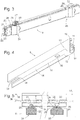
- Fig. 1 shows a perspective view of a household refrigerator with a body 1 and a door 2.
- refrigerated goods in the form of pull-out boxes 4, 5 and a pull-out tray 6 are shown.
- the tray comprises a storage plate 7 made of safety glass and supporting profiles 8 enclosing side edges of the plate 7, only one of which is visible in the figure.
- the tray 6 is slidably guided by telescopic extensions, which in the Fig. 1 inserted position of the tray 6 shown in a lower region of the support profiles 8, below the shelf 7, are hidden.
- Corresponding telescopic extensions also carry the two pull-out boxes 4, 5.
- the upper area of the cooling space 3 left empty can be fitted with further refrigerated goods carriers, in particular in the form of stationary or movable trays.
- Fig. 2 shows the tray 6 and the telescopic extensions 9 carrying it in an exploded perspective view.
- the extruded carrier profiles 8 made of metal or plastic, preferably of aluminum, each have a section 10 below the storage plate 7 of essentially rectangular or trapezoidal cross-section, with a horizontal upper flank 11 which delimits a groove which clamps the plate 7, and an outer and a lower flank 12, 13 which are cut away over the major part of its length to form a recess 14 which can accommodate and hide a telescopic extension 9 in the pushed-together state.
- a hollow bead 15 is formed, into which angled ends of wire brackets 16, 17, which form a railing of the storage plate 7, engage.
- the telescopic extension 9 is in Fig. 3 shown in an enlarged perspective view.
- the telescopic extension 9 is assembled in a manner known per se from two half-extensions, each with an inner rail 20 or 22 and an outer rail 21 or 23 encompassing the inner rail 20, 22 to form two longitudinal ball bearings.
- the inner rail 20 is on one Fixed inside wall of the body 1, the rails 21, 22 are firmly connected to each other, and on the outer rail 23 two adapters 24, 25 are locked for mounting the support profile 8.
- the front adapter 24 which is adjacent to the door 2, is injection-molded in one piece from plastic and has an approximately L-shaped body in cross section with a buffer 26 resting on the upper side of the outer rail 23 and a locking projection 27 protruding upward from the buffer 26 of a letter T, from the crossbar flexible tongues 28 protruding downwards. Outside of the tongues 28 facing away from each other are convexly curved.
- the second adapter 25, which is removed from the door 2 likewise has a base body of approximately L-shaped cross section with a buffer 26 resting on the outer rail 23.
- the buffer 26 is delimited in the longitudinal direction of the telescopic extension 9 by two inclined surfaces 29, each of which is extend to below the upper edge of the outer rail 23.
- a ⁇ - or mushroom-shaped leaf spring 30 protrudes from the buffer of the adapter 25, the two ends of which are embedded in a form-fitting manner in the body of the adapter 25.
- Both adapters 24, 25 are mirror-symmetrical with respect to a vertical central plane, so that identical front or rear adapters 24, 25 can be used on the telescopic extensions 9 located opposite each other in mirror image.
- Fig. 4 shows in a perspective view from below the support profile 8, which for mounting on the telescopic extension 9 of the Fig. 3 is provided.
- a window 32 is cut on a horizontal support surface 31 of the carrier profile 8, which forms the upper end of the recess 14, adjacent to the front end of the recess 14, a slot 33 extends to the rear edge of the support surface 31.
- the tray 6 If the tray 6 is to be attached to the telescopic extensions 9 mounted on the walls of the body 1, it is first inserted into the cooling space 3 with the rear edge hanging obliquely, the rear edges of the contact surfaces 31 of the two support profiles 8 on the outer rails 21, 23 of the two telescopic extensions 9 come to rest between the adapters 24, 25. When the tray 6 is pushed deeper into the cooling space 3, the rear edges of the support surfaces 31 slide along the rails 21, 23, finally reach the front inclined surfaces 29 of the two rear adapters 25 and slide upwards thereon. The leaf springs 30 move into the slots 33.
- the tray 6 can be pivoted horizontally; the windows 32 are placed so that they fall over the locking projections 27 of the two front adapters 24 in this position. If the in Fig. 5 shown final position of the tray 6 is reached, the bearing surface 31 on the buffers 26 of the adapters 24, 25, the bent tongues 28 of the locking projection 27 are slightly pressed against each other in contact with the edges of the window 32, and an obliquely upwards and after directed section 35 of the leaf spring 30 is slightly elastically deflected upwards in contact with the front edge 34 of the slot 33.
- the tensioning force of the spring is sufficient to hold the storage plate securely in the horizontal even when it is so heavily loaded in a front edge area 36 in front of the two front adapters 24 that the common center of gravity of the tray 6 and the refrigerated goods located thereon lies in front of the adapters 24.
- the tension of the tongues 28 and the leaf spring 30 fixes the support profile 8 to the telescopic extension 9 without play. In order to detach it again, it must first be in at its front end, i.e. the left end Fig. 5 , be raised. Like at the in Fig. 5 To recognize the curvature of the tongues 28 shown, this is only possible by a simultaneous deformation of the tongues 28, that is, an initial resistance must be overcome. If the tongues 28 give way and the carrier profile 8 comes free from the latching projection 27, there is a high probability that the profile 8 swivels up much further than would be necessary to release the latching projection 27 alone. However, the leaf spring 30 can yield to a large extent as a result of the force occurring on the rear adapter 25, so that damage is not to be feared here.
Landscapes
- Engineering & Computer Science (AREA)
- Chemical & Material Sciences (AREA)
- Combustion & Propulsion (AREA)
- Physics & Mathematics (AREA)
- Mechanical Engineering (AREA)
- Thermal Sciences (AREA)
- General Engineering & Computer Science (AREA)
- Devices That Are Associated With Refrigeration Equipment (AREA)
- Warehouses Or Storage Devices (AREA)
- Freezers Or Refrigerated Showcases (AREA)
Description
- Die vorliegende Erfindung betrifft ein Kältegerät, insbesondere ein Haushaltskältegerät, mit einem Kühlraum, in dem ein Kühlgutträger auf Teleskopauszügen verschiebbar gehalten ist. Ein solches Kältegerät ist zum Beispiel aus
DE 2005 021 558 A1 bekannt. - Der Kühlgutträger und der Teleskopauszug dieses bekannten Kältegeräts weisen zwei Paare von ineinander greifenden Vorsprüngen und Aufnahmen auf, die den Kühlgutträger und den Teleskopauszug miteinander verbinden. Vorsprung und Aufnahme des ersten, türnahen Paars greifen in vertikaler Richtung ineinander; Vorsprung und Aufnahme des zweiten, rückwandnahen Paars tun es in Verschiebungsrichtung des Kühlgutträgers.
- Wenn der Kühlgutträger ausgebaut werden soll, muss zunächst ein vorderer Bereich der Kühlgutträgers angehoben werden, um Vorsprung und Aufnahme des ersten Paars voneinander zu lösen. Dabei schwenkt der Kühlgutträger um eine rückwärtige Kante, und wenn beim Anheben des vorderen Bereichs des Kühlgutträgers unachtsam vorgegangen wird, können an Aufnahme und Vorsprung des zweiten Paars beträchtliche vertikale Kräfte auftreten, die, da Aufnahme und Vorsprung des zweiten Paars im Wesentlichen nur in Auszugrichtung gegeneinander bewegbar sind, zu einer Beschädigung führen können.
- Das Risiko einer Beschädigung ist umso größer, je weniger Spiel in vertikaler Richtung zwischen Aufnahme und Vorsprung des zweiten Paars besteht. Um einen sicheren Halt des Kühlgutträgers auf dem Teleskopauszug zu gewährleisten, ist es jedoch wünschenswert, dieses Spiel gering zu halten.
-
KR 10-2008-0036821 A -
DE 10 2007 051 343 A1 offenbart eine Teleskopauszuganordnung umfassend zwei Teleskopauszüge, die jeweils an einem gemeinsamen Rahmen ortsfeste Schienen und wenigstens einen in Tiefenrichtung der Teleskopauszuganordnung beweglichen Teil aufweisen, und ein Ablageteil, das an den beweglichen Teilen gehalten ist. Jedes bewegliche Teil und das Ablageteil weisen paarweise in der Tiefenrichtung ineinander steckbare Konturen sowie zwei miteinander überlappende, quer zur Tiefenrichtung ausgerichtete Raststufen zum Verriegeln der Konturen im ineinander gesteckten Zustand auf. -
DE 10 2005 021 558 A1 offenbart ein Kältegerät mit einem Kühlraum, in dem ein erster Kühlträger mithilfe von zwei Teleskopauszügen verschiebbar ist, wobei wenigstens der erste Kühlträger an wenigstens einem der Teleskopauszüge anhand mindestens eines Adapters gehalten ist, der zwischen den benachbarten Seiten des Teleskopauszuges und dem ersten Kühlgutträger angeordnet ist. -
DE 10 2006 018 203 A1 offenbart einen Fachboden für ein Kältegerät mit einer von einem Rahmen eingefassten Trägerplatte, wobei der Rahmen aus Extrusionprofilstücken und die Enden der Extrusionprofilstücke verbindenden Profilteilen zusammengefügt ist. Die Extrusionprofilstücke weisen im Querschnitt einen vertikalen und einen horizontalen Schenkel auf, wobei in einem von den beiden Schenkeln auf gespannten Winkel ein Teleskopauszug aufgenommen ist. - Aufgabe der vorliegenden Erfindung ist, das bekannte Kältegerät so weiter zu entwickeln, dass die Gefahr einer Beschädigung beim Lösen des Kühlgutträgers von den Teleskopauszügen wenigstens weitgehend ausgeräumt ist.
- Die Aufgabe wird durch die Merkmale des ersten Anspruchs gelöst. Erfindungsgemäß, greifen bei einem Kältegerät, insbesondere einem Haushaltskältegerät mit einem Kühlraum, in dem ein Kühlgutträger auf Teleskopauszügen verschiebbar gehalten ist und jeder Kühlgutträger und der Teleskopauszug wenigstens zwei Paare von ineinander greifenden Vorsprüngen und Aufnahmen aufweisen, wobei der Vorsprung und die Aufnahme des ersten Paars in vertikaler und horizontaler Richtung einander fixierend ineinandergreifen und der Vorsprung und die Aufnahme des zweiten Paars in vertikaler Richtung einander fixierend ineinandergreifen, die Aufnahme und der Vorsprung des zweiten Paars in vertikaler Richtung zumindest weitgehend spielfrei elastisch ineinandergreifen. Durch eine durch den Vorsprung bewirkte federelastische Fixierung zwischen der Aufnahme und dem Vorsprung des zweiten Paares ist ein Abnehmen des Kühlgutträgers von den Teleskopauszügen mit deutlich verminderter Gefahr einer Beschädigung von Aufnahme und/oder Vorsprung lediglich durch ein durch Anheben des Kühlgutträgers und damit bewirktes Entkoppeln des ersten Paares möglich. Durch das Anheben ergibt sich eine fiktive Drehachse im Nahbereich des zweiten Vorsprungs.
- Bevorzugt ist die fiktive Drehachse dem Vorsprung des zweiten Paares in Auszugsrichtung des Kühlgutträgers aus dem Kühlraum nachgelagert.
- In vorteilhafter Weise sind die Aufnahme und der Vorsprung des ersten Paares in vertikaler Richtung und der Vorsprung und die Aufnahme des zweiten Paares in horizontaler Richtung zusammengefügt.
- Die oben beschriebenen Merkmale sind besonders vorteilhaft im Falle eines Kühlgutträgers, der einen mit Kühlgut beladbaren Bereich an einer von dem zweiten Paar abgewandten Seite des ersten Paars aufweist, da das spielfreie Ineinandergreifen des zweiten Paars ein Kippen des Kühlgutträgers auch dann verhindert, wenn dieser in besagtem Bereich jenseits des ersten Paares überladen ist.
- Um den Kühlgutträger in Verschiebungsrichtung spielfrei an den Teleskopauszügen zu verankern, ist der Vorsprung des ersten Paars vorzugsweise in der Verschiebungsrichtung elastisch verformbar und durch den Eingriff in die Aufnahme elastisch gestaucht.
- Um den Kühlgutträger an den Teleskopauszügen zu sichern, können der Vorsprung und die Aufnahme des ersten Paars zweckmäßigerweise aneinander verrastet sein. Wenn aufgrund der Verrastung zunächst ein Anfangswiderstand beim Anheben des Kühlgutträgers überwunden werden muss, ist die Gefahr besonders groß, dass nach Überwindung dieses Anfangswiderstandes eine starke Kraft zwischen Vorsprung und Aufnahme des zweiten Paars wirkt, die dort zu Schäden führen könnte, wenn der Vorsprung des zweiten Paars nicht erfindungsgemäß elastisch verformbar wäre.
- Erfindungsgemäß ist das erste Paar von Vorsprung und Aufnahme näher als das zweite Paar einer Tür und das zweite Paar näher als das erste Paar einer Rückwand des Kältegeräts benachbart.
- Das zweite Paar kann dann als Aufnahme einen zur Rückwand des Kältegeräts hin offenen Schlitz des Kühlgutträgers und als Vorsprung einen sich von einem Fußpunkt am Teleskopauszug nach vorn und nach oben erstreckenden Federarm aufweisen.
- Vorzugsweise ist der Federarm so geformt, dass er durch Kontakt mit dem Kühlgutträger unter Spannung gesetzt wird, wenn dieser durch Ineinandergreifen von Vorsprung und Aufnahme des ersten Paars am Kühlgutträger fixiert ist.
- Vorzugsweise ist der Federarm Teil eines Federbügels, insbesondere Teil einer Ωförmigen Feder, die an zwei Fußpunkten verankert ist. Die zwei Arme einer solchen Feder stützen sich gegenseitig ab, auch wenn nur einer von ihnen den Kühlgutträger unmittelbar berührt, so dass die Gefahr einer dauerhaften Verformung der Feder beim Ein- und Ausbau des Kühlgutträgers gering ist.
- Vorzugsweise ist die Ω-förmige Feder Teil eines an den Teleskopschienen montierten spiegelsymmetrischen Adapters. Die Spiegelsymmetrie ermöglicht es, einen gleichen Adapter an zwei sich gegenüber liegenden Teleskopschienen zu montieren, wobei von den zwei Federarmen der Ω-förmigen Feder je nach Platzierung des Adapters verschiedene in die Aufnahme des Kühlgutträgers eingreifen.
- Zweckmäßig für eine stabile Unterstützung des Kühlgutträgers ist ferner, wenn die Teleskopschiene zwei über ihre Oberseite überstehende Puffer trägt, auf denen der Kühlgutträger aufliegt. Ein solcher Puffer kann jeweils Teil eines der oben erwähnten Adapter sein.
- Vorzugsweise weist wenigstens der hintere Puffer an einer Vorderseite eine schräge Flanke auf, die die Oberseite der Teleskopschiene kreuzt. Dies vereinfacht die Montage eines Kühlgutträgers auf der Teleskopschiene, indem eine Kante des Kühlgutträgers, die beim Einschieben des Kühlgutträgers in das Kältegerät über die Teleskopschiene gleitet, am Kreuzungspunkt zwischen der Oberseite der Teleskopschiene und der schrägen Flanke im wesentlichen widerstandslos auf die schräge, als Aufgleitebene dienende Flanke übergeht und an dieser hochgleitet, so dass schließlich der Kühlgutträger auf dem Puffer zu liegen kommt.
- Um beim Einschieben des Kühlgutträgers Aufnahme und Vorsprung des zweiten Paars bequem und sich aneinander in Eingriff zu bringen, ist der Vorsprung des zweiten Paars vorzugsweise an dem hinteren der Puffer verankert.
- Vorzugsweise ist der Kühlgutträger eine Abstellplatte, denn bei dieser ist die Gefahr besonders groß, dass sie in einem Randbereich jenseits des ersten Paars überladen wird und ins Kippen gerät, wenn sie nicht erfindungsgemäß gesichert ist. Die Erfindung ist aber auch auf einen Auszugkasten als Kühlgutträger anwendbar.
- Um zu verhindern, dass Kühlgut von der Abstellplatte herunterfällt, wenn diese in beladenem Zustand verschoben wird, sind zweckmäßigerweise am vorderen und hinteren Rand der Abstellplatte Geländer vorgesehen.
- Wenn die Abstellplatte zwischen zwei seitlichen Profilstücken eingefasst ist, können die Geländer zweckmäßigerweise in den Profilstücken verankert sein.
- Außerdem können solche seitlichen Profilstücke zweckmäßigerweise dazu dienen, die Teleskopauszüge im eingeschobenen Zustand zu verdecken.
- Weitere Merkmale und Vorteile der Erfindung ergeben sich aus der nachfolgenden Beschreibung von Ausführungsbeispielen unter Bezugnahme auf die beigefügten Figuren. Es zeigen:
- Fig. 1
- eine perspektivische Ansicht eines erfindungsgemäßen Kältegeräts;
- Fig. 2
- eine auseinander gezogene Ansicht eines Kühlgutträgers und zweier Teleskopauszüge;
- Fig. 3
- eine vergrößerte perspektivische Ansicht eines Teleskopauszugs;
- Fig. 4
- eine Ansicht eines zur Montage auf dem Teleskopauszug der
Fig. 3 vorgesehenen Rahmenprofils des Kühlgutträgers; und - Fig. 5
- einen schematischen Längsschnitt durch das auf dem Teleskopauszug montierte Rahmenprofil.
-
Fig. 1 zeigt eine perspektivische Ansicht eines Haushaltskältegeräts mit einem Korpus 1 und einer Tür 2. In einem Kühlraum 3 im Inneren des Geräts sind Kühlgutträger in Form von Auszugkästen 4, 5 sowie eines herausziehbaren Tablars 6 dargestellt. Das Tablar umfasst eine Abstellplatte 7 aus Sicherheitsglas sowie Seitenränder der Platte 7 einfassende Trägerprofile 8, von denen in der Figur nur eines sichtbar ist. Das Tablar 6 ist durch Teleskopauszüge verschiebbar geführt, die in der inFig. 1 gezeigten eingeschobenen Stellung des Tablars 6 in einem unteren Bereich der Trägerprofile 8, unterhalb der Abstellplatte 7, verborgen sind. Entsprechende Teleskopauszüge tragen auch die zwei Auszugkästen 4, 5. In dem in derFigur 1 leer gelassenen oberen Bereich des Kühlraums 3 können weitere Kühlgutträger, insbesondere in Form von stationären oder verschiebbaren Tablaren, angebracht sein. -
Fig. 2 zeigt das Tablar 6 und die es tragenden Teleskopauszüge 9 in einer auseinander gezogenen perspektivischen Ansicht. Die aus Metall oder Kunststoff, vorzugsweise aus Aluminium, extrudierten Trägerprofile 8 haben unterhalb der Abstellplatte 7 jeweils einen Abschnitt 10 von im Wesentlichen rechteckigem oder trapezförmigem Querschnitt, mit einer horizontalen oberen Flanke 11, die eine die Platte 7 klemmende Nut begrenzt, und einer äußeren und einer unteren Flanke 12, 13, die auf dem überwiegenden Teil ihrer Länge weggeschnitten sind, um eine Aussparung 14 zu bilden, die einen Teleskopauszug 9 im zusammengeschobenen Zustand aufnehmen und verbergen kann. - Am oberen Rand eines über die Abstellplatte 7 aufragenden Stegs jedes Trägerprofils 8 ist ein hohler Wulst 15 geformt, in den abgewinkelte Enden von ein Geländer der Abstellplatte 7 bildenden rechtwinklig gebogenen Drahtbügeln 16, 17 eingreifen.
- Der Teleskopauszug 9 ist in
Fig. 3 in einer vergrößerten perspektivischen Ansicht gezeigt. Der Teleskopauszug 9 ist in an sich bekannter Weise zusammengefügt aus zwei Halbauszügen mit jeweils einer inneren Schiene 20 bzw. 22 und einer die innere Schiene 20, 22 unter Ausbildung von zwei Längskugellagern umgreifenden äußeren Schiene 21 bzw. 23. Die innere Schiene 20 ist an einer Innenwand des Korpus 1 befestigt, die Schienen 21, 22 sind miteinander fest verbunden, und an der äußeren Schiene 23 sind zwei Adapter 24, 25 für die Montage des Trägerprofils 8 verrastet. - Der vordere, zur Tür 2 benachbarte Adapter 24 ist einteilig aus Kunststoff spritzgeformt und hat einen im Querschnitt in etwa L-förmigen Körper mit einem auf der Oberseite der äußeren Schiene 23 aufliegenden Puffer 26 und einen von dem Puffer 26 nach oben abstehenden Rastvorsprung 27 in Form eines Buchstaben T, von dessen Querbalken flexible Zungen 28 nach unten abstehenden. Voneinander abgewandte Außenseiten der Zungen 28 sind konvex gekrümmt.
- Der zweite, von der Tür 2 entfernte Adapter 25 hat ebenfalls einen Grundkörper von in etwa L-förmigem Querschnitt mit einem auf der äußeren Schiene 23 aufliegenden Puffer 26. Der Puffer 26 ist in Längsrichtung des Teleskopauszugs 9 durch zwei Schrägflächen 29 begrenzt, die sich jeweils bis unter die Oberkante der äußeren Schiene 23 erstrecken.
- Von dem Puffer des Adapters 25 steht eine Ω- oder pilzförmig gebogene Blattfeder 30 ab, deren zwei Enden formschlüssig in den Körper des Adapters 25 eingebettet sind.
- Beide Adapter 24, 25 sind spiegelsymmetrisch bezüglich einer vertikalen Mittelebene, so dass jeweils identische vordere bzw. hintere Adapter 24, 25 auf den sich spiegelbildlich gegenüberliegenden Teleskopauszügen 9 verwendet werden können.
-
Fig. 4 zeigt in einer perspektivischen Ansicht von unten das Trägerprofil 8, das zur Montage auf dem Teleskopauszug 9 derFig. 3 vorgesehen ist. An einer horizontalen Auflagefläche 31 des Trägerprofils 8, die den oberen Abschluss der Aussparung 14 bildet, ist benachbart zum vorderen Ende der Aussparung 14 ein Fenster 32 geschnitten, ein Schlitz 33 erstreckt sich bis zum hinteren Rand der Auflagefläche 31. - Wenn das Tablar 6 auf den an den Wänden des Korpus 1 montierten Teleskopauszügen 9 angebracht werden soll, wird es zunächst mit schräg herabhängender Hinterkante in den Kühlraum 3 eingeführt, wobei die hinteren Ränder der Auflageflächen 31 der zwei Trägerprofile 8 auf den äußeren Schienen 21, 23 der beiden Teleskopauszüge 9 zwischen den Adaptern 24, 25 zu liegen kommen. Wenn das Tablar 6 tiefer in den Kühlraum 3 hinein geschoben wird, gleiten die Hinterkanten der Auflageflächen 31 auf den Schienen 21, 23 entlang, erreichen schließlich die vorderen Schrägflächen 29 der beiden hinteren Adapter 25 und gleiten an diesen aufwärts. Die Blattfedern 30 rücken in die Schlitze 33 ein. Wenn eine Vorderkante 34 des Schlitzes 33 gegen die Blattfeder 30 stößt, kann das Tablar 6 in die Horizontale geschwenkt werden; die Fenster 32 sind so platziert, dass sie in dieser Stellung über die Rastvorsprünge 27 der zwei vorderen Adapter 24 fallen.
Wenn die inFig. 5 gezeigte endgültige Stellung des Tablars 6 erreicht ist, liegt die Auflagefläche 31 auf den Puffern 26 der Adapter 24, 25 auf, die gebogenen Zungen 28 des Rastvorsprungs 27 sind im Kontakt mit den Rändern des Fensters 32 leicht gegeneinander gedrückt, und ein schräg nach oben und nach vor gerichteter Abschnitt 35 der Blattfeder 30 ist im Kontakt mit der Vorderkante 34 des Schlitzes 33 geringfügig elastisch nach oben ausgelenkt. Die Spannkraft der Feder genügt, um die Abstellplatte auch dann sicher in der Horizontalen zu halten, wenn sie in einem vorderen Randbereich 36, vor den zwei vorderen Adaptern 24, so schwer beladen ist, dass der gemeinsame Schwerpunkt des Tablars 6 und des darauf befindlichen Kühlguts vor den Adaptern 24 liegt. - Durch die Spannung der Zungen 28 und der Blattfeder 30 ist das Trägerprofil 8 spielfrei an dem Teleskopauszug 9 fixiert. Um es wieder zu lösen, muss es zunächst an seinem vorderen Ende, das heißt dem linken Ende in
Fig. 5 , angehoben werden. Wie an der inFig. 5 gezeigten Krümmung der Zungen 28 zu erkennen, ist dies ist nur durch eine gleichzeitige Verformung der Zungen 28 möglich, das heißt es muss ein Anfangswiderstand überwunden werden. Wenn die Zungen 28 nachgeben und das Trägerprofil 8 vom Rastvorsprung 27 freikommt, ist die Wahrscheinlichkeit groß, dass das Profil 8 wesentlich weiter hochschwenkt, als dies allein zum Lösen des Rastvorsprungs 27 erforderliche wäre. Der infolge dessen am hinteren Adapter 25 auftretenden Kraft kann die Blattfeder 30 jedoch in weitem Umfang nachgeben, so dass eine Beschädigung hier nicht zu befürchten ist.
Claims (13)
- Kältegerät, insbesondere Haushaltskältegerät, mit einem Kühlraum (3), in dem ein Kühlgutträger (6) auf Teleskopauszügen (9) verschiebbar gehalten ist, wobei der Kühlgutträger (6) und jeder Teleskopauszug (9) wenigstens zwei Paare von ineinandergreifenden Vorsprüngen (27, 30) und Aufnahmen (32, 33) aufweisen, und wobei der Vorsprung (27) und die Aufnahme (32) des ersten Paars in vertikaler und horizontaler Richtung einander fixierend ineinandergreifen und der Vorsprung (30) und die Aufnahme (33) des zweiten Paars in vertikaler Richtung einander fixierend ineinandergreifen, wobei die Aufnahme (33) und der Vorsprung (30) des zweiten Paars wenigstens in vertikaler Richtung zumindest weitgehend spielfrei elastisch gehalten ineinandergreifen, dadurch gekennzeichnet, dass das erste Paar (27, 32) näher als das zweite Paar (30, 33) einer Tür (2) und das zweite Paar (30, 33) näher als das erste Paar (27, 33) einer Rückwand des Kältegeräts benachbart ist.
- Kältegerät nach Anspruch 1, dadurch gekennzeichnet, dass der Kühlgutträger (6) einen mit Kühlgut beladbaren Bereich (36) an einer von dem zweiten Paar (30, 33) abgewandten Seite des ersten Paars (27, 32) aufweist.
- Kältegerät nach Anspruch 1 oder 2, dadurch gekennzeichnet, dass der Vorsprung (27) des ersten Paars in der Verschiebungsrichtung des Kühlgutträgers (6) elastisch verformbar und durch den Eingriff in die Aufnahme (32) elastisch gestaucht ist.
- Kältegerät nach Anspruch 1, 2 oder 3, dadurch gekennzeichnet, dass der Vorsprung (27) und die Aufnahme (32) des ersten Paars aneinander verrastet sind.
- Kältegerät nach einem der Ansprüche 1 bis 4, dadurch gekennzeichnet, dass das zweite Paar als Aufnahme (33) einen zur Rückwand hin offenen Schlitz (33) des Kühlgutträgers (6) und als Vorsprung (30) einen sich von einem Fußpunkt am Teleskopauszug (9) nach vorn und nach oben erstreckenden Federarm (35) aufweist.
- Kältegerät nach Anspruch 5, dadurch gekennzeichnet, dass der Federarm (35) Teil einer an zwei Fußpunkten verankerten Federbügel, insbesondere einer Ω-förmigen Feder (30) ist.
- Kältegerät nach Anspruch 6, dadurch gekennzeichnet, dass die Feder (30) Teil eines am Teleskopauszug (9) montierten spiegelsymmetrischen Adapters (25) ist.
- Kältegerät nach einem der vorhergehenden Ansprüche, dadurch gekennzeichnet, dass die Teleskopschiene (9) zwei über eine Oberseite der Teleskopschiene überstehende Puffer (26) trägt, auf denen der Kühlgutträger (6) aufliegt, und dass wenigstens der hintere Puffer (26) an einer Vorderseite eine schräge Flanke (29) aufweist, die die Oberseite der Teleskopschiene (9) kreuzt.
- Kältegerät nach Anspruch 8, dadurch gekennzeichnet, dass der Vorsprung (30) des zweiten Paars an dem hinteren Puffer (26) verankert ist.
- Kältegerät nach einem der vorhergehenden Ansprüche, dadurch gekennzeichnet, dass der Kühlgutträger (6) eine Abstellplatte (7) umfasst.
- Kältegerät nach Anspruch 10, dadurch gekennzeichnet, dass am vorderen und hinteren Rand der Abstellplatte (7) Geländer (16, 17) vorgesehen sind.
- Kältegerät nach Anspruch 11, dadurch gekennzeichnet, dass die Abstellplatte (7) zwischen zwei seitlichen Profilstücken (8) eingefasst ist, und dass die Geländer (16, 17) in den Profilstücken (8) verankert sind.
- Kältegerät nach einem der vorhergehenden Ansprüche, dadurch gekennzeichnet, dass die Abstellplatte (7) zwischen zwei seitlichen Profilstücken (8) eingefasst ist, die im eingeschobenen Zustand die Teleskopauszüge (9) verdecken.
Priority Applications (1)
| Application Number | Priority Date | Filing Date | Title |
|---|---|---|---|
| PL10173647T PL2317260T3 (pl) | 2009-09-02 | 2010-08-23 | Urządzenie chłodzące z wyciąganym nośnikiem przedmiotu chłodzenia |
Applications Claiming Priority (1)
| Application Number | Priority Date | Filing Date | Title |
|---|---|---|---|
| DE102009029137A DE102009029137A1 (de) | 2009-09-02 | 2009-09-02 | Kältegerät mit ausziehbarem Kühlgutträger |
Publications (3)
| Publication Number | Publication Date |
|---|---|
| EP2317260A2 EP2317260A2 (de) | 2011-05-04 |
| EP2317260A3 EP2317260A3 (de) | 2017-06-07 |
| EP2317260B1 true EP2317260B1 (de) | 2020-07-22 |
Family
ID=43524858
Family Applications (1)
| Application Number | Title | Priority Date | Filing Date |
|---|---|---|---|
| EP10173647.8A Active EP2317260B1 (de) | 2009-09-02 | 2010-08-23 | Kältegerät mit ausziehbarem kühlgutträger |
Country Status (3)
| Country | Link |
|---|---|
| EP (1) | EP2317260B1 (de) |
| DE (1) | DE102009029137A1 (de) |
| PL (1) | PL2317260T3 (de) |
Families Citing this family (3)
| Publication number | Priority date | Publication date | Assignee | Title |
|---|---|---|---|---|
| KR102591763B1 (ko) * | 2016-11-04 | 2023-10-23 | 삼성전자주식회사 | 냉장고 |
| CN112444035B (zh) * | 2019-09-03 | 2023-11-17 | 博西华电器(江苏)有限公司 | 制冷器具 |
| CN112781302A (zh) * | 2021-01-05 | 2021-05-11 | 青岛海尔电冰箱有限公司 | 搁架支撑组件及冰箱 |
Citations (1)
| Publication number | Priority date | Publication date | Assignee | Title |
|---|---|---|---|---|
| WO2008051000A1 (en) * | 2006-10-24 | 2008-05-02 | Lg Electronics Inc. | Refrigerator |
Family Cites Families (7)
| Publication number | Priority date | Publication date | Assignee | Title |
|---|---|---|---|---|
| AT394303B (de) * | 1990-06-11 | 1992-03-10 | Alfit Ag | Schublade |
| AT409073B (de) * | 1997-07-03 | 2002-05-27 | Blum Gmbh Julius | Schublade |
| DE10233094A1 (de) * | 2002-07-19 | 2004-04-15 | Kapolnek Gmbh | Schwingungs- und körperschallisolierendes Lager |
| DE102005021558A1 (de) | 2005-05-10 | 2006-11-16 | BSH Bosch und Siemens Hausgeräte GmbH | Kältegerät mit ausziehbarem Kühlgutträger |
| DE102006018203A1 (de) * | 2006-04-19 | 2007-10-25 | BSH Bosch und Siemens Hausgeräte GmbH | Fachboden für ein Kältegerät |
| KR101275569B1 (ko) * | 2006-10-24 | 2013-06-14 | 엘지전자 주식회사 | 냉장고용 수납박스 장착구조 |
| DE102007051343A1 (de) * | 2007-10-26 | 2009-04-30 | BSH Bosch und Siemens Hausgeräte GmbH | Teleskopauszuganordnung |
-
2009
- 2009-09-02 DE DE102009029137A patent/DE102009029137A1/de not_active Withdrawn
-
2010
- 2010-08-23 EP EP10173647.8A patent/EP2317260B1/de active Active
- 2010-08-23 PL PL10173647T patent/PL2317260T3/pl unknown
Patent Citations (1)
| Publication number | Priority date | Publication date | Assignee | Title |
|---|---|---|---|---|
| WO2008051000A1 (en) * | 2006-10-24 | 2008-05-02 | Lg Electronics Inc. | Refrigerator |
Also Published As
| Publication number | Publication date |
|---|---|
| EP2317260A2 (de) | 2011-05-04 |
| DE102009029137A1 (de) | 2011-03-03 |
| PL2317260T3 (pl) | 2020-12-28 |
| EP2317260A3 (de) | 2017-06-07 |
Similar Documents
| Publication | Publication Date | Title |
|---|---|---|
| EP1807668B1 (de) | Teleskopschienensystem und kühl- und/oder gefriergerät | |
| DE10216769A1 (de) | Konsole für Tragböden in Haushaltsgeräten | |
| DE102005021591A1 (de) | Haushaltsgerät mit Teleskopauszug | |
| DE202005021758U1 (de) | Teleskopauszug für ein Kältegerät | |
| EP0041616A1 (de) | Auszugführung für aus einem Gestell ausziehbare Träger, wie Schubladen oder dergleichen | |
| EP1846711B1 (de) | Kältegerät mit ausziehbarem kühlgutträger | |
| DE102010004219A1 (de) | Kühl- und/oder Gefriergerät | |
| EP2317260A2 (de) | Kältegerät mit ausziehbarem Kühlgutträger | |
| WO2003016802A1 (de) | Kältegerät mit herausziehbarem lagergutträger | |
| WO2007122076A2 (de) | Teleskopauszug für ein kältegerät | |
| EP3852579B1 (de) | Schubkasten und einheit aus einer auszugsführung und einem schubkasten | |
| AT520673B1 (de) | Bewegungsmechanismus für ein Führungssystem | |
| EP2378923B1 (de) | Kältegerät mit teleskopauszug | |
| WO2013164179A1 (de) | Haltevorrichtung für ein tragelement eines schrankes sowie kühl-, gefrierschrank oder weinlagerungsschrank | |
| DE202007006386U1 (de) | Elektrisches Küchengerät | |
| EP4286749A1 (de) | Schnellbefestigungssystem für einen teleskopauszug | |
| EP2980513B1 (de) | Kühlgutablage für ein kältegerät | |
| EP2317261A2 (de) | Kältegerät mit ausziehbarem Kühlgutträger | |
| AT513581B1 (de) | Auszugssystem für Schubelemente | |
| EP2454542A2 (de) | Kühlgutträger für ein kältegerät | |
| EP2156122B1 (de) | Fachboden für ein kältegerät | |
| WO2012010442A2 (de) | Kältegerät mit transportsicherung | |
| EP3722712B1 (de) | Haushaltskältegerät | |
| WO2007128732A1 (de) | Kühlgutträger für ein kältegerät | |
| EP0976995A2 (de) | Kühlgerät mit Tragboden |
Legal Events
| Date | Code | Title | Description |
|---|---|---|---|
| PUAI | Public reference made under article 153(3) epc to a published international application that has entered the european phase |
Free format text: ORIGINAL CODE: 0009012 |
|
| AK | Designated contracting states |
Kind code of ref document: A2 Designated state(s): AL AT BE BG CH CY CZ DE DK EE ES FI FR GB GR HR HU IE IS IT LI LT LU LV MC MK MT NL NO PL PT RO SE SI SK SM TR |
|
| AX | Request for extension of the european patent |
Extension state: BA ME RS |
|
| RIN1 | Information on inventor provided before grant (corrected) |
Inventor name: SEN, HUESEYIN Inventor name: SCHLANDER, ULRICH |
|
| RAP1 | Party data changed (applicant data changed or rights of an application transferred) |
Owner name: BSH HAUSGERAETE GMBH |
|
| PUAL | Search report despatched |
Free format text: ORIGINAL CODE: 0009013 |
|
| AK | Designated contracting states |
Kind code of ref document: A3 Designated state(s): AL AT BE BG CH CY CZ DE DK EE ES FI FR GB GR HR HU IE IS IT LI LT LU LV MC MK MT NL NO PL PT RO SE SI SK SM TR |
|
| AX | Request for extension of the european patent |
Extension state: BA ME RS |
|
| RIC1 | Information provided on ipc code assigned before grant |
Ipc: F25D 25/02 20060101AFI20170502BHEP |
|
| PUAL | Search report despatched |
Free format text: ORIGINAL CODE: 0009013 |
|
| STAA | Information on the status of an ep patent application or granted ep patent |
Free format text: STATUS: REQUEST FOR EXAMINATION WAS MADE |
|
| 17P | Request for examination filed |
Effective date: 20171207 |
|
| RBV | Designated contracting states (corrected) |
Designated state(s): AL AT BE BG CH CY CZ DE DK EE ES FI FR GB GR HR HU IE IS IT LI LT LU LV MC MK MT NL NO PL PT RO SE SI SK SM TR |
|
| STAA | Information on the status of an ep patent application or granted ep patent |
Free format text: STATUS: EXAMINATION IS IN PROGRESS |
|
| 17Q | First examination report despatched |
Effective date: 20180316 |
|
| GRAP | Despatch of communication of intention to grant a patent |
Free format text: ORIGINAL CODE: EPIDOSNIGR1 |
|
| STAA | Information on the status of an ep patent application or granted ep patent |
Free format text: STATUS: GRANT OF PATENT IS INTENDED |
|
| INTG | Intention to grant announced |
Effective date: 20200110 |
|
| GRAJ | Information related to disapproval of communication of intention to grant by the applicant or resumption of examination proceedings by the epo deleted |
Free format text: ORIGINAL CODE: EPIDOSDIGR1 |
|
| STAA | Information on the status of an ep patent application or granted ep patent |
Free format text: STATUS: EXAMINATION IS IN PROGRESS |
|
| GRAP | Despatch of communication of intention to grant a patent |
Free format text: ORIGINAL CODE: EPIDOSNIGR1 |
|
| STAA | Information on the status of an ep patent application or granted ep patent |
Free format text: STATUS: GRANT OF PATENT IS INTENDED |
|
| INTC | Intention to grant announced (deleted) | ||
| INTG | Intention to grant announced |
Effective date: 20200310 |
|
| GRAS | Grant fee paid |
Free format text: ORIGINAL CODE: EPIDOSNIGR3 |
|
| GRAA | (expected) grant |
Free format text: ORIGINAL CODE: 0009210 |
|
| STAA | Information on the status of an ep patent application or granted ep patent |
Free format text: STATUS: THE PATENT HAS BEEN GRANTED |
|
| AK | Designated contracting states |
Kind code of ref document: B1 Designated state(s): AL AT BE BG CH CY CZ DE DK EE ES FI FR GB GR HR HU IE IS IT LI LT LU LV MC MK MT NL NO PL PT RO SE SI SK SM TR |
|
| REG | Reference to a national code |
Ref country code: GB Ref legal event code: FG4D Free format text: NOT ENGLISH |
|
| REG | Reference to a national code |
Ref country code: CH Ref legal event code: EP |
|
| REG | Reference to a national code |
Ref country code: DE Ref legal event code: R096 Ref document number: 502010016705 Country of ref document: DE |
|
| REG | Reference to a national code |
Ref country code: AT Ref legal event code: REF Ref document number: 1293793 Country of ref document: AT Kind code of ref document: T Effective date: 20200815 |
|
| REG | Reference to a national code |
Ref country code: IE Ref legal event code: FG4D Free format text: LANGUAGE OF EP DOCUMENT: GERMAN |
|
| REG | Reference to a national code |
Ref country code: LT Ref legal event code: MG4D |
|
| PG25 | Lapsed in a contracting state [announced via postgrant information from national office to epo] |
Ref country code: LT Free format text: LAPSE BECAUSE OF FAILURE TO SUBMIT A TRANSLATION OF THE DESCRIPTION OR TO PAY THE FEE WITHIN THE PRESCRIBED TIME-LIMIT Effective date: 20200722 Ref country code: HR Free format text: LAPSE BECAUSE OF FAILURE TO SUBMIT A TRANSLATION OF THE DESCRIPTION OR TO PAY THE FEE WITHIN THE PRESCRIBED TIME-LIMIT Effective date: 20200722 Ref country code: PT Free format text: LAPSE BECAUSE OF FAILURE TO SUBMIT A TRANSLATION OF THE DESCRIPTION OR TO PAY THE FEE WITHIN THE PRESCRIBED TIME-LIMIT Effective date: 20201123 Ref country code: NO Free format text: LAPSE BECAUSE OF FAILURE TO SUBMIT A TRANSLATION OF THE DESCRIPTION OR TO PAY THE FEE WITHIN THE PRESCRIBED TIME-LIMIT Effective date: 20201022 Ref country code: GR Free format text: LAPSE BECAUSE OF FAILURE TO SUBMIT A TRANSLATION OF THE DESCRIPTION OR TO PAY THE FEE WITHIN THE PRESCRIBED TIME-LIMIT Effective date: 20201023 Ref country code: FI Free format text: LAPSE BECAUSE OF FAILURE TO SUBMIT A TRANSLATION OF THE DESCRIPTION OR TO PAY THE FEE WITHIN THE PRESCRIBED TIME-LIMIT Effective date: 20200722 Ref country code: SE Free format text: LAPSE BECAUSE OF FAILURE TO SUBMIT A TRANSLATION OF THE DESCRIPTION OR TO PAY THE FEE WITHIN THE PRESCRIBED TIME-LIMIT Effective date: 20200722 Ref country code: ES Free format text: LAPSE BECAUSE OF FAILURE TO SUBMIT A TRANSLATION OF THE DESCRIPTION OR TO PAY THE FEE WITHIN THE PRESCRIBED TIME-LIMIT Effective date: 20200722 Ref country code: BG Free format text: LAPSE BECAUSE OF FAILURE TO SUBMIT A TRANSLATION OF THE DESCRIPTION OR TO PAY THE FEE WITHIN THE PRESCRIBED TIME-LIMIT Effective date: 20201022 |
|
| PG25 | Lapsed in a contracting state [announced via postgrant information from national office to epo] |
Ref country code: LV Free format text: LAPSE BECAUSE OF FAILURE TO SUBMIT A TRANSLATION OF THE DESCRIPTION OR TO PAY THE FEE WITHIN THE PRESCRIBED TIME-LIMIT Effective date: 20200722 Ref country code: IS Free format text: LAPSE BECAUSE OF FAILURE TO SUBMIT A TRANSLATION OF THE DESCRIPTION OR TO PAY THE FEE WITHIN THE PRESCRIBED TIME-LIMIT Effective date: 20201122 |
|
| PG25 | Lapsed in a contracting state [announced via postgrant information from national office to epo] |
Ref country code: NL Free format text: LAPSE BECAUSE OF FAILURE TO SUBMIT A TRANSLATION OF THE DESCRIPTION OR TO PAY THE FEE WITHIN THE PRESCRIBED TIME-LIMIT Effective date: 20200722 |
|
| REG | Reference to a national code |
Ref country code: CH Ref legal event code: PL |
|
| REG | Reference to a national code |
Ref country code: DE Ref legal event code: R097 Ref document number: 502010016705 Country of ref document: DE |
|
| PG25 | Lapsed in a contracting state [announced via postgrant information from national office to epo] |
Ref country code: MC Free format text: LAPSE BECAUSE OF FAILURE TO SUBMIT A TRANSLATION OF THE DESCRIPTION OR TO PAY THE FEE WITHIN THE PRESCRIBED TIME-LIMIT Effective date: 20200722 Ref country code: LU Free format text: LAPSE BECAUSE OF NON-PAYMENT OF DUE FEES Effective date: 20200823 Ref country code: RO Free format text: LAPSE BECAUSE OF FAILURE TO SUBMIT A TRANSLATION OF THE DESCRIPTION OR TO PAY THE FEE WITHIN THE PRESCRIBED TIME-LIMIT Effective date: 20200722 Ref country code: SM Free format text: LAPSE BECAUSE OF FAILURE TO SUBMIT A TRANSLATION OF THE DESCRIPTION OR TO PAY THE FEE WITHIN THE PRESCRIBED TIME-LIMIT Effective date: 20200722 Ref country code: LI Free format text: LAPSE BECAUSE OF NON-PAYMENT OF DUE FEES Effective date: 20200831 Ref country code: CH Free format text: LAPSE BECAUSE OF NON-PAYMENT OF DUE FEES Effective date: 20200831 Ref country code: CZ Free format text: LAPSE BECAUSE OF FAILURE TO SUBMIT A TRANSLATION OF THE DESCRIPTION OR TO PAY THE FEE WITHIN THE PRESCRIBED TIME-LIMIT Effective date: 20200722 Ref country code: DK Free format text: LAPSE BECAUSE OF FAILURE TO SUBMIT A TRANSLATION OF THE DESCRIPTION OR TO PAY THE FEE WITHIN THE PRESCRIBED TIME-LIMIT Effective date: 20200722 Ref country code: EE Free format text: LAPSE BECAUSE OF FAILURE TO SUBMIT A TRANSLATION OF THE DESCRIPTION OR TO PAY THE FEE WITHIN THE PRESCRIBED TIME-LIMIT Effective date: 20200722 |
|
| REG | Reference to a national code |
Ref country code: BE Ref legal event code: MM Effective date: 20200831 |
|
| PLBE | No opposition filed within time limit |
Free format text: ORIGINAL CODE: 0009261 |
|
| STAA | Information on the status of an ep patent application or granted ep patent |
Free format text: STATUS: NO OPPOSITION FILED WITHIN TIME LIMIT |
|
| PG25 | Lapsed in a contracting state [announced via postgrant information from national office to epo] |
Ref country code: AL Free format text: LAPSE BECAUSE OF FAILURE TO SUBMIT A TRANSLATION OF THE DESCRIPTION OR TO PAY THE FEE WITHIN THE PRESCRIBED TIME-LIMIT Effective date: 20200722 |
|
| GBPC | Gb: european patent ceased through non-payment of renewal fee |
Effective date: 20201022 |
|
| 26N | No opposition filed |
Effective date: 20210423 |
|
| PG25 | Lapsed in a contracting state [announced via postgrant information from national office to epo] |
Ref country code: SK Free format text: LAPSE BECAUSE OF FAILURE TO SUBMIT A TRANSLATION OF THE DESCRIPTION OR TO PAY THE FEE WITHIN THE PRESCRIBED TIME-LIMIT Effective date: 20200722 |
|
| PG25 | Lapsed in a contracting state [announced via postgrant information from national office to epo] |
Ref country code: FR Free format text: LAPSE BECAUSE OF NON-PAYMENT OF DUE FEES Effective date: 20200922 |
|
| PG25 | Lapsed in a contracting state [announced via postgrant information from national office to epo] |
Ref country code: GB Free format text: LAPSE BECAUSE OF NON-PAYMENT OF DUE FEES Effective date: 20201022 Ref country code: IE Free format text: LAPSE BECAUSE OF NON-PAYMENT OF DUE FEES Effective date: 20200823 Ref country code: SI Free format text: LAPSE BECAUSE OF FAILURE TO SUBMIT A TRANSLATION OF THE DESCRIPTION OR TO PAY THE FEE WITHIN THE PRESCRIBED TIME-LIMIT Effective date: 20200722 Ref country code: BE Free format text: LAPSE BECAUSE OF NON-PAYMENT OF DUE FEES Effective date: 20200831 |
|
| REG | Reference to a national code |
Ref country code: NL Ref legal event code: MP Effective date: 20200722 |
|
| REG | Reference to a national code |
Ref country code: AT Ref legal event code: MM01 Ref document number: 1293793 Country of ref document: AT Kind code of ref document: T Effective date: 20200823 |
|
| PG25 | Lapsed in a contracting state [announced via postgrant information from national office to epo] |
Ref country code: AT Free format text: LAPSE BECAUSE OF NON-PAYMENT OF DUE FEES Effective date: 20200823 |
|
| PG25 | Lapsed in a contracting state [announced via postgrant information from national office to epo] |
Ref country code: MT Free format text: LAPSE BECAUSE OF FAILURE TO SUBMIT A TRANSLATION OF THE DESCRIPTION OR TO PAY THE FEE WITHIN THE PRESCRIBED TIME-LIMIT Effective date: 20200722 Ref country code: CY Free format text: LAPSE BECAUSE OF FAILURE TO SUBMIT A TRANSLATION OF THE DESCRIPTION OR TO PAY THE FEE WITHIN THE PRESCRIBED TIME-LIMIT Effective date: 20200722 |
|
| PG25 | Lapsed in a contracting state [announced via postgrant information from national office to epo] |
Ref country code: MK Free format text: LAPSE BECAUSE OF FAILURE TO SUBMIT A TRANSLATION OF THE DESCRIPTION OR TO PAY THE FEE WITHIN THE PRESCRIBED TIME-LIMIT Effective date: 20200722 |
|
| PGFP | Annual fee paid to national office [announced via postgrant information from national office to epo] |
Ref country code: IT Payment date: 20220831 Year of fee payment: 13 |
|
| REG | Reference to a national code |
Ref country code: DE Ref legal event code: R084 Ref document number: 502010016705 Country of ref document: DE |
|
| REG | Reference to a national code |
Ref country code: DE Ref legal event code: R081 Ref document number: 502010016705 Country of ref document: DE Owner name: BSH HAUSGERAETE GMBH, DE Free format text: FORMER OWNER: ROBERT BOSCH GMBH, 70469 STUTTGART, DE |
|
| PG25 | Lapsed in a contracting state [announced via postgrant information from national office to epo] |
Ref country code: IT Free format text: LAPSE BECAUSE OF NON-PAYMENT OF DUE FEES Effective date: 20230823 |
|
| PGFP | Annual fee paid to national office [announced via postgrant information from national office to epo] |
Ref country code: DE Payment date: 20250831 Year of fee payment: 16 |
|
| PGFP | Annual fee paid to national office [announced via postgrant information from national office to epo] |
Ref country code: TR Payment date: 20250813 Year of fee payment: 16 Ref country code: PL Payment date: 20250814 Year of fee payment: 16 |