EP2317145B1 - Kupplung für eine Schraubenspindelpumpe - Google Patents
Kupplung für eine Schraubenspindelpumpe Download PDFInfo
- Publication number
- EP2317145B1 EP2317145B1 EP10013619.1A EP10013619A EP2317145B1 EP 2317145 B1 EP2317145 B1 EP 2317145B1 EP 10013619 A EP10013619 A EP 10013619A EP 2317145 B1 EP2317145 B1 EP 2317145B1
- Authority
- EP
- European Patent Office
- Prior art keywords
- coupling
- pump
- shaft
- drive
- gearwheel
- Prior art date
- Legal status (The legal status is an assumption and is not a legal conclusion. Google has not performed a legal analysis and makes no representation as to the accuracy of the status listed.)
- Active
Links
Images

Classifications
-
- F—MECHANICAL ENGINEERING; LIGHTING; HEATING; WEAPONS; BLASTING
- F04—POSITIVE - DISPLACEMENT MACHINES FOR LIQUIDS; PUMPS FOR LIQUIDS OR ELASTIC FLUIDS
- F04C—ROTARY-PISTON, OR OSCILLATING-PISTON, POSITIVE-DISPLACEMENT MACHINES FOR LIQUIDS; ROTARY-PISTON, OR OSCILLATING-PISTON, POSITIVE-DISPLACEMENT PUMPS
- F04C2/00—Rotary-piston machines or pumps
- F04C2/08—Rotary-piston machines or pumps of intermeshing-engagement type, i.e. with engagement of co-operating members similar to that of toothed gearing
- F04C2/12—Rotary-piston machines or pumps of intermeshing-engagement type, i.e. with engagement of co-operating members similar to that of toothed gearing of other than internal-axis type
- F04C2/14—Rotary-piston machines or pumps of intermeshing-engagement type, i.e. with engagement of co-operating members similar to that of toothed gearing of other than internal-axis type with toothed rotary pistons
- F04C2/16—Rotary-piston machines or pumps of intermeshing-engagement type, i.e. with engagement of co-operating members similar to that of toothed gearing of other than internal-axis type with toothed rotary pistons with helical teeth, e.g. chevron-shaped, screw type
- F04C2/165—Rotary-piston machines or pumps of intermeshing-engagement type, i.e. with engagement of co-operating members similar to that of toothed gearing of other than internal-axis type with toothed rotary pistons with helical teeth, e.g. chevron-shaped, screw type having more than two rotary pistons with parallel axes
-
- F—MECHANICAL ENGINEERING; LIGHTING; HEATING; WEAPONS; BLASTING
- F04—POSITIVE - DISPLACEMENT MACHINES FOR LIQUIDS; PUMPS FOR LIQUIDS OR ELASTIC FLUIDS
- F04C—ROTARY-PISTON, OR OSCILLATING-PISTON, POSITIVE-DISPLACEMENT MACHINES FOR LIQUIDS; ROTARY-PISTON, OR OSCILLATING-PISTON, POSITIVE-DISPLACEMENT PUMPS
- F04C15/00—Component parts, details or accessories of machines, pumps or pumping installations, not provided for in groups F04C2/00 - F04C14/00
- F04C15/0057—Driving elements, brakes, couplings, transmission specially adapted for machines or pumps
- F04C15/0061—Means for transmitting movement from the prime mover to driven parts of the pump, e.g. clutches, couplings, transmissions
- F04C15/0073—Couplings between rotors and input or output shafts acting by interengaging or mating parts, i.e. positive coupling of rotor and shaft
-
- F—MECHANICAL ENGINEERING; LIGHTING; HEATING; WEAPONS; BLASTING
- F16—ENGINEERING ELEMENTS AND UNITS; GENERAL MEASURES FOR PRODUCING AND MAINTAINING EFFECTIVE FUNCTIONING OF MACHINES OR INSTALLATIONS; THERMAL INSULATION IN GENERAL
- F16D—COUPLINGS FOR TRANSMITTING ROTATION; CLUTCHES; BRAKES
- F16D3/00—Yielding couplings, i.e. with means permitting movement between the connected parts during the drive
- F16D3/50—Yielding couplings, i.e. with means permitting movement between the connected parts during the drive with the coupling parts connected by one or more intermediate members
- F16D3/64—Yielding couplings, i.e. with means permitting movement between the connected parts during the drive with the coupling parts connected by one or more intermediate members comprising elastic elements arranged between substantially-radial walls of both coupling parts
- F16D3/68—Yielding couplings, i.e. with means permitting movement between the connected parts during the drive with the coupling parts connected by one or more intermediate members comprising elastic elements arranged between substantially-radial walls of both coupling parts the elements being made of rubber or similar material
-
- F—MECHANICAL ENGINEERING; LIGHTING; HEATING; WEAPONS; BLASTING
- F04—POSITIVE - DISPLACEMENT MACHINES FOR LIQUIDS; PUMPS FOR LIQUIDS OR ELASTIC FLUIDS
- F04C—ROTARY-PISTON, OR OSCILLATING-PISTON, POSITIVE-DISPLACEMENT MACHINES FOR LIQUIDS; ROTARY-PISTON, OR OSCILLATING-PISTON, POSITIVE-DISPLACEMENT PUMPS
- F04C2270/00—Control; Monitoring or safety arrangements
- F04C2270/12—Vibration
Definitions
- the invention relates to a Mehrschraubensplndelpumpe mentioned in the preamble of claim 1 Art.
- Such pumps are for example from the DE 102 57 859 B4 .
- the promotion takes place via two or more interlocking conveyor screws, whose shafts are interconnected by toothed drives.
- a shaft hereinafter called the output shaft, is rotationally driven by an external motor and transmits its rotational movement within the pump housing via the gear drives to the other shafts.
- a shaft stub of the output shaft to which the drive shaft of the drive motor is coupled protrudes from the pump housing, a shaft stub of the output shaft to which the drive shaft of the drive motor is coupled. This can be done, for example, in a coaxial arrangement between the drive shaft and shaft stutters of the pump and with a rigid coupling. But since a precise alignment between the pump and the drive motor is not easy in such a construction, often an elastic coupling between the waves to be connected is set, for example, a known in the art elastomer coupling or torsionally flexible claw coupling.
- the drive side have a flange to flare the drive motor for blocking.
- the coupling is also rigid, since the motor and pump can be aligned very precisely with each other in this blocked arrangement. But even with these generic pumps misalignment and manufacturing tolerances lead to vibrations and unruhlgem running, affecting the longevity of the pump.
- the couplings may have elastic components, see, inter alia DE 600 03 093 T2 , however, are relatively large construction and require a separate coupling area.
- One of the shafts namely the output shaft driven by the external motor, has on the drive side a coupling piece for the coupling to the external drive motor.
- This coupling piece extends in its axial extent into the region of the flange and is suitably designed and arranged for the rigid coupling of the drive shaft of the motor with the output shaft of the pump.
- the coupling piece is accessible for the coupling of the drive shaft, on the other hand that the coupling piece is suitably shaped for the coupling of the drive shaft, e.g. by providing a suitably shaped groove into which a spring formed on the drive shaft can engage.
- shaft and coupling piece can also be coupled to each other differently, e.g. by screws.
- torsional vibration damping means ensure that the power transmission from the drive shaft to the output shaft is damped against shocks and uneven running.
- an at least partially flexurally elastic shaft can be used as a torsional vibration damping means.
- the torsional vibration damping means but a flexible coupling, as they are known for example from the prior art.
- Constructively simple The formation of the elastic coupling takes place in that the coupling part for the rigid engine coupling is simultaneously formed on the conveyor side as a coupling part for the elastic coupling.
- This coupling piece is to some extent simultaneously part of two couplings, namely on its drive side rigid coupling body, that is part of a rigid coupling, and on its delivery side elastic coupling body, that is part of an elastic coupling.
- This description as an elastic or rigid coupling body is not based on the material of the body, but on its function.
- the elasticity of the coupling results from the features of claim 1.
- FIG. 1 shows the drive end of a screw pump 1, the housing 2 consists of several parts. Not shown is the conveying range of the pump 1 with the two screw conveyors, because this area is not significant for the present invention. This range can therefore be arbitrary and as known in the art, for example as in the DE 102 57 859 , of the DE 715 860 , of the US 1,762,708 or the DE 102009040643 shown.
- the bearing housing 3 adjoins the conveyor region with the bearings 4 for the shafts 5, 6 of the screw conveyors.
- the delivery area and this shaft storage area are separated by seals. Again, the structural details can be neglected, because they are not significant for the invention.
- the bearing housing 3 is followed by the transmission housing 7, which terminates the pump 1 on the drive side.
- the transmission housing 7 Within this gear housing 7, the rotational coupling of the two shafts 5, 6 by on both shafts 5, 6 mounted and meshing gears 8, 9.
- the upper of the two in the sectional drawing to be recognized waves 5 is used for coupling to an external motor, while the lower shaft 6 in the transmission housing 7 ends.
- the lower shaft 7 may be formed as usual in the art, ie, for example, as in FIG. 1 shown deposed towards the end.
- a spacer bushing 11 to which the seated on the shaft 6 gear carrier 12 abuts.
- the gear carrier 12 has an inner groove 13 into which engages a mounted on the shaft 6 key 14.
- the gear carrier 12, on which the gear 9 is seated is provided with an enlarged flange 15, which is provided in the axial direction of the shaft 6 with holes which are in alignment with threaded holes in the gear 9.
- the gear 9 is screwed onto the gear carrier 12.
- the attachment of the gear carrier 12 on the shaft 6 via a clamping plate 17 which is placed on the gear carrier 12, and is clamped by a screwed axially into the shaft 6 hex bolt 18 firmly on the shaft 6.
- the gear housing 7 is on the drive side formed as Verblockungsflansch 20 for the blocked connection of the motor housing.
- Verblockungsflansch 20 In the axial extension of the output shaft 5 of the pump 1, the Verblockungsflansch 20 has a circular opening 21 in which the coupling end 22 of the output shaft 5 of the pump 1 opens.
- the further description is additionally made with reference to FIGS FIG. 2 in which the spatial conditions are better recognizable.
- the coupling end 22 is formed as a sleeve 23 with a free diameter 24 in the interior, in which the coupling end of the drive shaft of the motor can be inserted.
- the sleeve 23 has an inner, radially outwardly extending and extending in the axial direction groove 25 into which a complementarily formed on the motor drive shaft spring (not shown) can engage positively.
- a complementarily formed on the motor drive shaft spring (not shown) can engage positively.
- On the motor side facing away from the sleeve 23 is provided with a plurality of circumferentially distributed coupling claws 26.
- the gear carrier 27 of the upper shaft 5 is greatly modified from the gear carrier 12 of the lower shaft 6 described above. Like the lower shaft 6 is also the upper shaft 5 offset towards the end (see FIG. 1 ). It sits again in abutment up to the paragraph a spacer bushing 28, to which the seated on the shaft 5 gear carrier 27 abuts.
- the gear carrier 27 has again an inner groove 29, in which a mounted on the shaft 5 key 30 engages.
- the gear carrier 27, on which the gear 8 is seated is provided with a widened flange 31, which is provided in the axial direction of the shaft 5 with threaded holes 32, which are in alignment with holes 33 in the gear 8.
- the gear carrier 27 of the upper shaft 5 is formed on the drive side with circumferentially distributed coupling claws 40, which correspond to the claws 26 of the sleeve 23 described above.
- the gear carrier 27 is thus at the same time also coupling part.
- an elastomeric star 41 is arranged, the arms 42 of which lie between the adjacent jaws 26, 40 of the two coupling parts 22, 27.
- the gear carrier 27 is in its the coupling claws 40 having portion of a larger diameter than the gear mounted thereon 8.
- cylindrical concave indentations 42 are provided to allow axial freedom of movement for the gear 9 of the first shaft 6.
- the indentations 42 are thus e.g. formed complementary to the smoothed cross-sectional contour of the first gear 9.
Landscapes
- Engineering & Computer Science (AREA)
- General Engineering & Computer Science (AREA)
- Mechanical Engineering (AREA)
- Rotary Pumps (AREA)
Description
- Die Erfindung betrifft eine Mehrschraubensplndelpumpe der im Oberbegriff des Anspruches 1 genannten Art.
- Derartige Pumpen sind z.B. aus der
DE 102 57 859 B4 ,Fig. 2 oder derDE 715 860 bekannt, und dienen der Förderung verschiedenster Förderprodukte. Die Förderung erfolgt dabei über zwei oder mehr ineinander greifende Förderschrauben, deren Wellen durch Zahntriebe miteinander verbunden sind. In der Regel wird bei diesen Pumpen eine Welle, nachfolgend Abtriebswelle genannt, von einem externen Motor drehangetrieben und überträgt seine Drehbewegung Innerhalb des Pumpengehäuses über die Zahntriebe auf die anderen Wellen. Ohne Elnschränkung der Allgemeinheit soll nachfolgend nur noch von zwei Wellen und also einer Doppelschraubenspindelpumpe die Rede sein. - Bei einigen Pumpenkonstruktionen ragt aus dem Pumpengehäuse ein Wellenstutzen der Abtriebswelle heraus, an den die Antriebswelle des Antriebsmotors gekuppelt wird. Dies kann z.B. in koaxialer Anordnung zwischen Antriebswelle und Wellenstutren der Pumpe erfolgen und mit einer starren Kupplung. Da aber eine genaue Ausrichtung zwischen Pumpe und Antriebsmotor bei einer solchen Konstruktion nicht einfach Ist, wird häufig eine elastische Kupplung zwischen die zu verbindenden Wellen gesetzt, z.B. eine im Stand der Technik bekannte Elastomerkupplung bzw. drehelastische Klauenkupplung.
- In alternativer Konstruktion dazu gibt es gattungsgemäße Pumpen, die antriebsseitig einen Flansch aufweisen, um daran den Antriebsmotor zur Verblockung anzuflanschen. Innerhalb der Flanschverbindung erfolgt auch die Kupplung zwischen Motorantriebswelle und Pumpenabtriebswelle. Die Kupplung erfolgt dabei Immer starr, da Motor und Pumpe bei dieser verblockten Anordnung sehr exakt zueinander ausgerichtet werden können. Aber auch bei diesen gattungsgemäße Pumpen führen Justierfehler und Fertigungstoleranzen zu Schwingungen und unruhlgem Laufen, die die Langlebigkeit der Pumpe beeinträchtigen. Auch hier können die Kupplungen elastische Komponenten aufweisen, siehe unter anderem
DE 600 03 093 T2 , die allerdings relativ großbauend sind und einen separaten Kupplungsbereich erfordern. - Es ist die Aufgabe der vorliegenden Erfindung hier Abhilfe zu schaffen.
- Diese Aufgabe wird gelöst mit den Merkmalen des Anspruchs 1. Vorteilhafte Ausgestaltungen sind in den Unteransprüchen angegeben.
- Eine der Wellen, nämlich die vom externen Motor angetriebene Abtriebswelle, weist antriebsseitig ein Kupplungsstück für die Ankupplung an den externen Antriebsmotor auf. Dieses Kupplungsstück reicht in seiner axialen Erstreckung bis in den Bereich des Flansches hinein und ist für die starre Ankupplung der Antriebswelle des Motors mit der Abtriebswelle der Pumpe geeignet ausgebildet und angeordnet. Das bedeutet zum einen, dass das Kupplungsstück zugänglich ist für das Ankuppeln der Antriebswelle, zum anderen, dass das Kupplungsstück geeignet ausgeformt ist für das Ankuppeln der Antriebswelle, z.B. durch das Vorsehen einer geeignet geformten Nut, in die eine an der Antriebswelle ausgeformte Feder eingreifen kann. Welle und Kupplungsstück können aber auch anders aneinander gekuppelt werden, z.B. durch Schrauben.
- Erfindungsgemäß sind nun förderseitlg dieses Kupplungsstückes zwischen Abtriebswelle und Kupplungsstück drehschwingungsdämpfende Mittel angeordnet. Diese drehschwlngungsdämpfenden Mittel sorgen dafür, dass die Kraftübertragung von der Antriebswelle auf die Abtriebswelle gegen Stöße und unruhiges Laufen gedämpft erfolgt. Beispielsweise kann eine zumindest bereichsweise biegeelastische Welle als drehschwingungsdämpfendes Mittel verwendet werden.
- Vorteilhaft sind die drehschwingungsdämpfenden Mittel aber eine elastische Kupplung, wie sie z.B. aus dem Stand der Technik bekannt sind. Konstruktiv besonders einfach erfolgt die Ausbildung der elastischen Kupplung dadurch, dass das Kupplungsteil für die starre Motorankupplung gleichzeitig förderseitig als Kupplungsteil für die elastische Kupplung ausgebildet ist. Dieses Kupplungsstück ist gewissermaßen gleichzeitig Bestandteil von zwei Kupplungen, nämlich auf seiner Antriebsseite starrer Kupplungskörper, also Bestandteil einer starren Kupplung, und auf seiner Förderseite elastischer Kupplungskörper, also Bestandteil einer elastischen Kupplung. Diese Umschreibung als elastischer bzw. starrer Kopplungskörper ist dabei nicht auf das Material des Körpers bezogen, sondern auf dessen Funktion. Die Elastizität der Kupplung ergibt sich aus den Merkmalen des Anspruchs 1.
- Mit Vorteil sind die Merkmale des Anspruchs 3 vorgesehen. Es ist dadurch möglich, den Zahnkranz auf der zweiten Welle auszutauschen, ohne die Kupplung oder die Abtriebswelle ausbauen zu müssen, well die erforderliche Bewegungsfrelhelt in axialer Richtung gewährleistet ist.
- Nachfolgend soll die Erfindung anhand eines Ausführungsbeispieles weiter erläutert werden. Es zeigen:
- Fig. 1
- eine Schnittansicht durch das antriebsseitige Ende einer erfindungsgemäßen Schraubenspindelpumpe, und
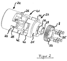
- Fig. 2
- eine Explosionsdarstellung des antriebsseitigen Endes der Abtriebswelle mit Kupplungselementen der Schraubenspindelpumpe gemäß der Konstruktion der
Fig. 1 . -
Figur 1 zeigt das antriebseitige Ende einer Schraubenspindelpumpe 1, deren Gehäuse 2 aus mehreren Teilen besteht. Nicht mehr dargestellt ist der Förderbereich der Pumpe 1 mit den beiden Förderschnecken, weil dieser Bereich für die vorliegende Erfindung nicht bedeutend ist. Dieser Bereich kann daher beliebig und wie im Stand der Technik bekannt ausgebildet sein, z.B. wie in derDE 102 57 859 , derDE 715 860 , derUS 1,762,708 oder derDE 102009040643 dargestellt. - Antriebsseitig schließt sich dem Förderbereich das Lagergehäuse 3 mit den Lagern 4 für die Wellen 5, 6 der Förderschnecken an. Der Förderbereich und dieser der Wellenlagerung dienende Bereich sind durch Dichtungen voneinander getrennt. Auch hier können die konstruktiven Details vernachlässigt werden, weil Sie für die Erfindung nicht bedeutsam sind.
- Dem Lagergehäuse 3 schließt sich das Getriebegehäuse 7 an, das die Pumpe 1 antriebsseitig abschließt. Innerhalb dieses Getriebegehäuses 7 erfolgt die Drehkopplung der beiden Wellen 5, 6 durch auf beiden Wellen 5, 6 angebrachte und miteinander kämmende Zahnräder 8, 9. Die obere der beiden in der Schnittzeichnung zu erkennenden Wellen 5 dient der Ankupplung an einen externen Motor, während die untere Welle 6 im Getriebegehäuse 7 endet.
- Die untere Welle 7 kann wie im Stand der Technik üblich ausgebildet sein, also z.B. wie in
Figur 1 dargestellt zum Ende hin abgesetzt. Darauf sitzt in Anschlag bis an den Absatz 10 eine Abstandsbuchse 11, an die der ebenfalls auf der Welle 6 sitzende Zahnradträger 12 anstößt. Der Zahnradträger 12 weist eine innere Nut 13 auf, in die eine auf der Welle 6 angebrachte Passfeder 14 eingreift. Zu seinem freien Ende hin ist der Zahnradträger 12, auf dem das Zahnrad 9 sitzt, mit einem verbreiterten Flansch 15 ausgestattet, der in Achsrichtung der Welle 6 mit Bohrungen versehen ist, die fluchtend zu Gewindelöchern im Zahnrad 9 stehen. Mittels durch die Bohrungen bis zu den Gewindelöchern verlaufender Schrauben 16 wird das Zahnrad 9 auf dem Zahnradträger 12 verschraubt. Die Befestigung des Zahnradträgers 12 auf der Welle 6 erfolgt über eine Spannscheibe 17, die auf den Zahnradträger 12 gelegt wird, und die von einer axial in die Welle 6 eingeschraubten Sechskantschraube 18 fest auf die Welle 6 gespannt wird. - Das Getriebegehäuse 7 ist antriebsseitig als Verblockungsflansch 20 für den verblockten Anschluss des Motorgehäuses ausgebildet. Zur besseren Übersicht, und weil die vorliegende Erfindung nicht den Motor betrifft, ist dieser nicht dargestellt. In axialer Verlängerung der Abtriebswelle 5 der Pumpe 1 weist der Verblockungsflansch 20 eine kreisförmige Öffnung 21 auf, in der das Kupplungsendstück 22 der Abtriebswelle 5 der Pumpe 1 mündet. Die weitere Beschreibung erfolgt zusätzlich unter Bezugnahme auf die
Figur 2 , in der die räumlichen Verhältnisse besser erkennbar sind. Das Kupplungsendstück 22 ist als Hülse 23 ausgebildet mit einem freien Durchmesser 24 im Inneren, in das das Kupplungsende der Antriebswelle des Motors einsteckbar ist. Für die Drehkopplung weist die Hülse 23 eine innere, sich radial nach außen erstreckende und in Axialrichtung verlaufende Nut 25 auf, in die eine komplementär auf der Motorantriebswelle ausgebildete Feder (nicht dargestellt) formschlüssig eingreifen kann. Auf der motorabgewandten Seite ist die Hülse 23 mit mehreren umfangsverteilten Kupplungsklauen 26 versehen. - Der Zahnradträger 27 der oberen Welle 5 ist gegenüber dem oben beschriebenen Zahnradträger 12 der unteren Welle 6 stark modifiziert. Wie die untere Welle 6 ist auch die obere Welle 5 zum Ende hin abgesetzt (siehe
Figur 1 ). Darauf sitzt erneut in Anschlag bis an den Absatz eine Abstandsbuchse 28, an die der ebenfalls auf der Welle 5 sitzende Zahnradträger 27 anstößt. Der Zahnradträger 27 weist wieder eine innere Nut 29 auf, in die eine auf der Welle 5 angebrachte Passfeder 30 eingreift. Zu seinem freien Ende hin ist der Zahnradträger 27, auf dem das Zahnrad 8 sitzt, mit einem verbreiterten Flansch 31 ausgestattet, der in Achsrichtung der Welle 5 mit Gewindelöchern 32 versehen ist, die fluchtend zu Bohrungen 33 im Zahnrad 8 stehen. Mittels von hinten durch die Bohrungen 33 des Zahnrades 8 bis zu den Gewindelöchern 32 des Zahnradträgers 27 verlaufender Schrauben 35 wird das Zahnrad 8 auf dem Zahnradträger 27 verschraubt. Die Verschraubung erfolgt also in entgegen gesetzter Richtung wie bei der unteren Welle 6. Die Befestigung des Zahnradträgers 27 hingegen erfolgt erneut über eine Spannscheibe 36, die auf einen inneren Absatz 37 des Zahnradträgers 27 gelegt wird, und die von einer axial in die Welle 5 eingeschraubten Sechskantschraube 38 fest auf die Welle 5 gespannt wird. - Der Zahnradträger 27 der oberen Welle 5 ist antriebsseitig mit umfangsverteilten Kupplungsklauen 40 ausgebildet, die zu den Klauen 26 der oben beschriebenen Hülse 23 korrespondieren. Der Zahnradträger 27 ist also zugleich auch Kupplungsteil. Zwischen die beiden Kupplungsteile 22, 27 wird ein Elastomerstern 41 angeordnet, dessen Arme 42 sich zwischen die benachbarten Klauen 26, 40 der beiden Kupplungsteile 22, 27 legen.
- Der Zahnradträger 27 ist in seinem die Kupplungsklauen 40 aufweisenden Bereich von einem größeren Durchmesser als das auf ihm befestigte Zahnrad 8. In diesem Bereich vergrößerten Durchmessers sind zylindrische konkav geformte Einbuchtungen 42 vorgesehen, um axiale Bewegungsfreiheit für das Zahnrad 9 der ersten Welle 6 zu ermöglichen. Die Einbuchtungen 42 sind also z.B. komplementär zur geglätteten Querschnittskontur des ersten Zahnrades 9 ausgebildet.
Claims (3)
- Schraubenspindelpumpe (1) mit einem Pumpengehäuse (2, 3, 7) und mit mehreren Förderschrauben, die innerhalb des Pumpengehäuses (2) in dessen Förderbereich angeordnet sind, wobei die Förderschrauben Wellen (5, 6) aufweisen, die sich in axialer Richtung bis zum antriebsseitigen Ende der Pumpe (1) bis in einen Getriebebereich (7) erstrecken, in dem die Wellen (5, 6) Zahnräder (8, 9) aufweisen, mittels derer die Wellen (5, 6) drehgekoppelt sind, wobei eine der Wellen (5) antriebsseitig ein Kupplungsstück (22) für die Ankupplung an einen externen Antriebsmotor aufweist, wobei weiterhin das Pumpengehäuse (2, 3, 7) antriebsseitig für die Verblockung mit dem Antriebsmotor mit einem Flansch (20) ausgebildet ist, und das Kupplungsstück (22) der Abtriebswelle (5) der Pumpe (1) sich in axialer Richtung bis in den Bereich dieses Flansches (20) erstreckt und für die starre Ankupplung der Antriebswelle des Motors mit der Abtriebswelle (5) der Pumpe (1) geeignet ausgebildet und angeordnet ist, dadurch gekennzeichnet, dass förderseitig dieses Kupplungsstückes (22) zwischen Welle (5) und Kupplungsstück (22) drehschwingungsdämpfende Mittel (26, 40, 41) angeordnet sind, dass die drehschwingungsdämpfenden Mittel eine elastische Kupplung (22, 26; 27, 40; 41) sind, dass das Kupplungsstück (22) für die starre Motorankupplung förderseitig als Kupplungsteil (26) für die elastische Kupplung ausgebildet ist, dass das Zahnrad (8) der Abtriebswelle (5) auf einem auf der Abtriebswelle (5) befestigten Zahnradträger (27) angeordnet Ist, und dass der Zahnradträger (27) antriebsseitig als Kupplungsteil (40) für die elastische Kupplung ausgebildet ist.
- Schraubenspindelpumpe (1) nach Anspruch 1, dadurch gekennzeichnet, dass die elastische Kupplung als Klauenkupplung (22, 26; 27, 40) mit dazwischenliegendem Elastomerstern (41)ausgebildet ist.
- Schraubenspindelpumpe (1) nach Anspruch 1 oder 2, dadurch gekennzeichnet, dass der Zahnradträger (27) In einem Teilbereich seiner axialen Erstreckung einen größeren Radius als das auf ihm angeordnete Zahnrad (8) aufweist, wobei er in diesem Bereich zylindrische konkav geformte Einbuchtungen (42) aufweist, die zur Ermöglichung einer axialen Bewegungsfreiheit der zweiten Welle (6) mit Zahnrad (9) komplementär dazu ausgebildet sind.
Applications Claiming Priority (1)
| Application Number | Priority Date | Filing Date | Title |
|---|---|---|---|
| DE202009014604U DE202009014604U1 (de) | 2009-10-29 | 2009-10-29 | Schraubenspindelpumpe mit Kupplung |
Publications (3)
| Publication Number | Publication Date |
|---|---|
| EP2317145A2 EP2317145A2 (de) | 2011-05-04 |
| EP2317145A3 EP2317145A3 (de) | 2015-04-29 |
| EP2317145B1 true EP2317145B1 (de) | 2016-05-04 |
Family
ID=41606502
Family Applications (1)
| Application Number | Title | Priority Date | Filing Date |
|---|---|---|---|
| EP10013619.1A Active EP2317145B1 (de) | 2009-10-29 | 2010-10-14 | Kupplung für eine Schraubenspindelpumpe |
Country Status (3)
| Country | Link |
|---|---|
| EP (1) | EP2317145B1 (de) |
| DE (1) | DE202009014604U1 (de) |
| ES (1) | ES2576732T3 (de) |
Families Citing this family (11)
| Publication number | Priority date | Publication date | Assignee | Title |
|---|---|---|---|---|
| DE102012001700B4 (de) | 2012-01-31 | 2013-09-12 | Jung & Co. Gerätebau GmbH | Zweispindelige Schraubenspindelpumpe in einflutiger Bauweise |
| DE102012001699B4 (de) | 2012-01-31 | 2013-09-12 | Jung & Co. Gerätebau GmbH | Zweispindelige Schraubenspindelpumpe in einflutiger Bauweise |
| DE202012000893U1 (de) | 2012-01-31 | 2012-02-28 | Jung & Co. Gerätebau GmbH | Zweispindelige Schraubenspindelpumpe in einflutiger Bauweise |
| DE202012000894U1 (de) | 2012-01-31 | 2012-03-01 | Jung & Co. Gerätebau GmbH | Zweispindelige Schraubenspindelpumpe in einflutiger Bauweise |
| DE102020108038A1 (de) | 2020-03-24 | 2021-09-30 | Nidec Gpm Gmbh | Elektrische schraubenspindelpumpe für flüssigkeiten |
| DE102021113724A1 (de) | 2021-05-27 | 2022-12-01 | Jung & Co. Gerätebau GmbH | Schraubenspindelpumpe in einflutiger Bauweise |
| FR3136522A1 (fr) * | 2022-06-10 | 2023-12-15 | Illinois Tool Works | Pompe à vis et ses composants |
| AT526449B1 (de) * | 2022-09-09 | 2024-05-15 | Johannes Kepler Univ Linz | Vorrichtung zur Reduktion von Druckpulsationen in einem Hydrauliksystem |
| EP4474650B1 (de) | 2023-06-09 | 2026-03-25 | Illinois Tool Works Inc. | Schraubenpumpe und ihre komponenten |
| US12533995B2 (en) | 2023-08-31 | 2026-01-27 | Illinois Tool Works Inc. | Battery electric vehicle temperature-regulation system |
| DE102024104230A1 (de) | 2024-02-15 | 2025-08-21 | FRISTAM Pumpen Schaumburg GmbH | Verdrängerpumpe mit Synchrongetriebe |
Family Cites Families (6)
| Publication number | Priority date | Publication date | Assignee | Title |
|---|---|---|---|---|
| US1762708A (en) | 1927-07-05 | 1930-06-10 | Allred Byron Harvey | Pump |
| DE715860C (de) | 1940-01-03 | 1942-01-08 | Fr August Neidig Soehne Maschi | Schraubenpumpe |
| FR2789462B1 (fr) * | 1999-02-09 | 2001-04-13 | Pompes Salmson Sa | Accouplement pour pompe et moteur de pompe |
| IT1313545B1 (it) * | 1999-09-23 | 2002-07-24 | Nuovo Pignone Spa | Gruppo di pompaggio a vite per il trattamento di fluidi in piu' fasi |
| DE10257859C5 (de) | 2002-12-11 | 2012-03-15 | Joh. Heinr. Bornemann Gmbh | Schraubenspindelpumpe |
| JP4294657B2 (ja) * | 2006-06-20 | 2009-07-15 | アスモ株式会社 | カップリング装置、モータ装置、及びワイパモータ |
-
2009
- 2009-10-29 DE DE202009014604U patent/DE202009014604U1/de not_active Expired - Lifetime
-
2010
- 2010-10-14 EP EP10013619.1A patent/EP2317145B1/de active Active
- 2010-10-14 ES ES10013619.1T patent/ES2576732T3/es active Active
Also Published As
| Publication number | Publication date |
|---|---|
| ES2576732T3 (es) | 2016-07-11 |
| EP2317145A2 (de) | 2011-05-04 |
| EP2317145A3 (de) | 2015-04-29 |
| DE202009014604U1 (de) | 2010-01-28 |
Similar Documents
| Publication | Publication Date | Title |
|---|---|---|
| EP2317145A2 (de) | Kupplung für eine Schraubenspindelpumpe | |
| DE102012002660B4 (de) | Elastische Doppel-Torsionskupplung | |
| EP0622557B1 (de) | Drehelastische Wellenkupplung | |
| DE102012005949A1 (de) | Zweispindelige Schraubenspindelpumpe in zweiflutiger Bauweise | |
| DE9304497U1 (de) | Wellenkupplung | |
| DE102015115001B4 (de) | Riemenscheiben-Baugruppe | |
| EP3234371B1 (de) | Kreiselpumpenlaufrad | |
| DE102012008761A1 (de) | Geteilter Statormantel | |
| EP2201257B1 (de) | Elastische wellenkupplung | |
| DE102014204221B4 (de) | Ausgleichskupplung mit Distanzelement sowie Kupplungsanordnung | |
| DE102005055605A1 (de) | Elastische Wellenkupplung | |
| EP1719928B1 (de) | Axialsicherungsanordnung für eine Lagerbüchse bei einem Kreuzgelenk | |
| DE19614677C2 (de) | Kurbelwelle, insbesondere für Einzylinder-Verbrennungsmotoren | |
| DE202011110002U1 (de) | Lamellenanbindung für drehsteife elastische Ganzstahl-Wellenkupplung | |
| DE102010032658A1 (de) | Drehmomentübertragungseinrichtung | |
| DE60003093T2 (de) | Kupplung für Pumpe und Motor | |
| WO2020114545A1 (de) | Aktiver wankstabilisator | |
| EP3314137B1 (de) | Kupplungsvorrichtung und klappeneinrichtung für eine frischluftanlage mit einer kupplungsvorrichtung | |
| DE102011088327A1 (de) | Kreuzgelenkwelle | |
| EP2397716B1 (de) | Elastische kupplung | |
| DE102008053916B4 (de) | Kupplung, Getriebe und Vorrichtung zum Überlagern von Bewegungen | |
| DE102012006633A1 (de) | Anordnung eines Maschinenelements auf einer Welle oder Achse sowie eine Welle oder Achse zur Fixierung eines Maschinenelements | |
| DE102013211936A1 (de) | Welle-Nabe-Verbindung | |
| DE102014014430A1 (de) | Wellenkupplung zum drehmomentübertragenden Verbinden von zwei Wellen unter Ausgleich eines eventuellen Achsversatzes der beiden Wellen | |
| EP2504593B1 (de) | Schwerlastklauenkupplung |
Legal Events
| Date | Code | Title | Description |
|---|---|---|---|
| PUAI | Public reference made under article 153(3) epc to a published international application that has entered the european phase |
Free format text: ORIGINAL CODE: 0009012 |
|
| AK | Designated contracting states |
Kind code of ref document: A2 Designated state(s): AL AT BE BG CH CY CZ DE DK EE ES FI FR GB GR HR HU IE IS IT LI LT LU LV MC MK MT NL NO PL PT RO RS SE SI SK SM TR |
|
| AX | Request for extension of the european patent |
Extension state: BA ME |
|
| PUAL | Search report despatched |
Free format text: ORIGINAL CODE: 0009013 |
|
| RIC1 | Information provided on ipc code assigned before grant |
Ipc: F04C 15/00 20060101ALI20150316BHEP Ipc: F04C 2/16 20060101AFI20150316BHEP Ipc: F16D 3/68 20060101ALI20150316BHEP |
|
| AK | Designated contracting states |
Kind code of ref document: A3 Designated state(s): AL AT BE BG CH CY CZ DE DK EE ES FI FR GB GR HR HU IE IS IT LI LT LU LV MC MK MT NL NO PL PT RO RS SE SI SK SM TR |
|
| AX | Request for extension of the european patent |
Extension state: BA ME |
|
| REG | Reference to a national code |
Ref country code: DE Ref legal event code: R079 Ref document number: 502010011583 Country of ref document: DE Free format text: PREVIOUS MAIN CLASS: F04C0002160000 Ipc: F16D0031040000 |
|
| 17P | Request for examination filed |
Effective date: 20151016 |
|
| RBV | Designated contracting states (corrected) |
Designated state(s): AL AT BE BG CH CY CZ DE DK EE ES FI FR GB GR HR HU IE IS IT LI LT LU LV MC MK MT NL NO PL PT RO RS SE SI SK SM TR |
|
| GRAP | Despatch of communication of intention to grant a patent |
Free format text: ORIGINAL CODE: EPIDOSNIGR1 |
|
| RIC1 | Information provided on ipc code assigned before grant |
Ipc: F16D 31/04 20060101AFI20151113BHEP Ipc: F04C 2/16 20060101ALI20151113BHEP Ipc: F04C 15/00 20060101ALI20151113BHEP |
|
| INTG | Intention to grant announced |
Effective date: 20151209 |
|
| GRAS | Grant fee paid |
Free format text: ORIGINAL CODE: EPIDOSNIGR3 |
|
| GRAA | (expected) grant |
Free format text: ORIGINAL CODE: 0009210 |
|
| AK | Designated contracting states |
Kind code of ref document: B1 Designated state(s): AL AT BE BG CH CY CZ DE DK EE ES FI FR GB GR HR HU IE IS IT LI LT LU LV MC MK MT NL NO PL PT RO RS SE SI SK SM TR |
|
| REG | Reference to a national code |
Ref country code: GB Ref legal event code: FG4D Free format text: NOT ENGLISH |
|
| REG | Reference to a national code |
Ref country code: CH Ref legal event code: EP |
|
| REG | Reference to a national code |
Ref country code: AT Ref legal event code: REF Ref document number: 797192 Country of ref document: AT Kind code of ref document: T Effective date: 20160515 |
|
| REG | Reference to a national code |
Ref country code: IE Ref legal event code: FG4D Free format text: LANGUAGE OF EP DOCUMENT: GERMAN |
|
| REG | Reference to a national code |
Ref country code: DE Ref legal event code: R096 Ref document number: 502010011583 Country of ref document: DE |
|
| REG | Reference to a national code |
Ref country code: ES Ref legal event code: FG2A Ref document number: 2576732 Country of ref document: ES Kind code of ref document: T3 Effective date: 20160711 |
|
| REG | Reference to a national code |
Ref country code: NL Ref legal event code: FP |
|
| REG | Reference to a national code |
Ref country code: LT Ref legal event code: MG4D |
|
| PG25 | Lapsed in a contracting state [announced via postgrant information from national office to epo] |
Ref country code: FI Free format text: LAPSE BECAUSE OF FAILURE TO SUBMIT A TRANSLATION OF THE DESCRIPTION OR TO PAY THE FEE WITHIN THE PRESCRIBED TIME-LIMIT Effective date: 20160504 Ref country code: NO Free format text: LAPSE BECAUSE OF FAILURE TO SUBMIT A TRANSLATION OF THE DESCRIPTION OR TO PAY THE FEE WITHIN THE PRESCRIBED TIME-LIMIT Effective date: 20160804 Ref country code: LT Free format text: LAPSE BECAUSE OF FAILURE TO SUBMIT A TRANSLATION OF THE DESCRIPTION OR TO PAY THE FEE WITHIN THE PRESCRIBED TIME-LIMIT Effective date: 20160504 |
|
| PG25 | Lapsed in a contracting state [announced via postgrant information from national office to epo] |
Ref country code: RS Free format text: LAPSE BECAUSE OF FAILURE TO SUBMIT A TRANSLATION OF THE DESCRIPTION OR TO PAY THE FEE WITHIN THE PRESCRIBED TIME-LIMIT Effective date: 20160504 Ref country code: LV Free format text: LAPSE BECAUSE OF FAILURE TO SUBMIT A TRANSLATION OF THE DESCRIPTION OR TO PAY THE FEE WITHIN THE PRESCRIBED TIME-LIMIT Effective date: 20160504 Ref country code: SE Free format text: LAPSE BECAUSE OF FAILURE TO SUBMIT A TRANSLATION OF THE DESCRIPTION OR TO PAY THE FEE WITHIN THE PRESCRIBED TIME-LIMIT Effective date: 20160504 Ref country code: HR Free format text: LAPSE BECAUSE OF FAILURE TO SUBMIT A TRANSLATION OF THE DESCRIPTION OR TO PAY THE FEE WITHIN THE PRESCRIBED TIME-LIMIT Effective date: 20160504 Ref country code: GR Free format text: LAPSE BECAUSE OF FAILURE TO SUBMIT A TRANSLATION OF THE DESCRIPTION OR TO PAY THE FEE WITHIN THE PRESCRIBED TIME-LIMIT Effective date: 20160805 Ref country code: PT Free format text: LAPSE BECAUSE OF FAILURE TO SUBMIT A TRANSLATION OF THE DESCRIPTION OR TO PAY THE FEE WITHIN THE PRESCRIBED TIME-LIMIT Effective date: 20160905 |
|
| PG25 | Lapsed in a contracting state [announced via postgrant information from national office to epo] |
Ref country code: RO Free format text: LAPSE BECAUSE OF FAILURE TO SUBMIT A TRANSLATION OF THE DESCRIPTION OR TO PAY THE FEE WITHIN THE PRESCRIBED TIME-LIMIT Effective date: 20160504 Ref country code: CZ Free format text: LAPSE BECAUSE OF FAILURE TO SUBMIT A TRANSLATION OF THE DESCRIPTION OR TO PAY THE FEE WITHIN THE PRESCRIBED TIME-LIMIT Effective date: 20160504 Ref country code: DK Free format text: LAPSE BECAUSE OF FAILURE TO SUBMIT A TRANSLATION OF THE DESCRIPTION OR TO PAY THE FEE WITHIN THE PRESCRIBED TIME-LIMIT Effective date: 20160504 Ref country code: SK Free format text: LAPSE BECAUSE OF FAILURE TO SUBMIT A TRANSLATION OF THE DESCRIPTION OR TO PAY THE FEE WITHIN THE PRESCRIBED TIME-LIMIT Effective date: 20160504 Ref country code: EE Free format text: LAPSE BECAUSE OF FAILURE TO SUBMIT A TRANSLATION OF THE DESCRIPTION OR TO PAY THE FEE WITHIN THE PRESCRIBED TIME-LIMIT Effective date: 20160504 |
|
| REG | Reference to a national code |
Ref country code: DE Ref legal event code: R097 Ref document number: 502010011583 Country of ref document: DE |
|
| PG25 | Lapsed in a contracting state [announced via postgrant information from national office to epo] |
Ref country code: PL Free format text: LAPSE BECAUSE OF FAILURE TO SUBMIT A TRANSLATION OF THE DESCRIPTION OR TO PAY THE FEE WITHIN THE PRESCRIBED TIME-LIMIT Effective date: 20160504 Ref country code: SM Free format text: LAPSE BECAUSE OF FAILURE TO SUBMIT A TRANSLATION OF THE DESCRIPTION OR TO PAY THE FEE WITHIN THE PRESCRIBED TIME-LIMIT Effective date: 20160504 Ref country code: BE Free format text: LAPSE BECAUSE OF NON-PAYMENT OF DUE FEES Effective date: 20161031 |
|
| PLBE | No opposition filed within time limit |
Free format text: ORIGINAL CODE: 0009261 |
|
| STAA | Information on the status of an ep patent application or granted ep patent |
Free format text: STATUS: NO OPPOSITION FILED WITHIN TIME LIMIT |
|
| 26N | No opposition filed |
Effective date: 20170207 |
|
| PG25 | Lapsed in a contracting state [announced via postgrant information from national office to epo] |
Ref country code: SI Free format text: LAPSE BECAUSE OF FAILURE TO SUBMIT A TRANSLATION OF THE DESCRIPTION OR TO PAY THE FEE WITHIN THE PRESCRIBED TIME-LIMIT Effective date: 20160504 |
|
| REG | Reference to a national code |
Ref country code: CH Ref legal event code: PL |
|
| GBPC | Gb: european patent ceased through non-payment of renewal fee |
Effective date: 20161014 |
|
| PG25 | Lapsed in a contracting state [announced via postgrant information from national office to epo] |
Ref country code: MC Free format text: LAPSE BECAUSE OF FAILURE TO SUBMIT A TRANSLATION OF THE DESCRIPTION OR TO PAY THE FEE WITHIN THE PRESCRIBED TIME-LIMIT Effective date: 20160504 |
|
| REG | Reference to a national code |
Ref country code: IE Ref legal event code: MM4A |
|
| REG | Reference to a national code |
Ref country code: FR Ref legal event code: ST Effective date: 20170630 |
|
| PG25 | Lapsed in a contracting state [announced via postgrant information from national office to epo] |
Ref country code: FR Free format text: LAPSE BECAUSE OF NON-PAYMENT OF DUE FEES Effective date: 20161102 Ref country code: CH Free format text: LAPSE BECAUSE OF NON-PAYMENT OF DUE FEES Effective date: 20161031 Ref country code: LI Free format text: LAPSE BECAUSE OF NON-PAYMENT OF DUE FEES Effective date: 20161031 Ref country code: GB Free format text: LAPSE BECAUSE OF NON-PAYMENT OF DUE FEES Effective date: 20161014 |
|
| PG25 | Lapsed in a contracting state [announced via postgrant information from national office to epo] |
Ref country code: LU Free format text: LAPSE BECAUSE OF NON-PAYMENT OF DUE FEES Effective date: 20161014 |
|
| PG25 | Lapsed in a contracting state [announced via postgrant information from national office to epo] |
Ref country code: IE Free format text: LAPSE BECAUSE OF NON-PAYMENT OF DUE FEES Effective date: 20161014 |
|
| REG | Reference to a national code |
Ref country code: BE Ref legal event code: MM Effective date: 20161031 |
|
| REG | Reference to a national code |
Ref country code: AT Ref legal event code: MM01 Ref document number: 797192 Country of ref document: AT Kind code of ref document: T Effective date: 20161014 |
|
| PG25 | Lapsed in a contracting state [announced via postgrant information from national office to epo] |
Ref country code: AT Free format text: LAPSE BECAUSE OF NON-PAYMENT OF DUE FEES Effective date: 20161014 |
|
| PG25 | Lapsed in a contracting state [announced via postgrant information from national office to epo] |
Ref country code: HU Free format text: LAPSE BECAUSE OF FAILURE TO SUBMIT A TRANSLATION OF THE DESCRIPTION OR TO PAY THE FEE WITHIN THE PRESCRIBED TIME-LIMIT; INVALID AB INITIO Effective date: 20101014 Ref country code: CY Free format text: LAPSE BECAUSE OF FAILURE TO SUBMIT A TRANSLATION OF THE DESCRIPTION OR TO PAY THE FEE WITHIN THE PRESCRIBED TIME-LIMIT Effective date: 20160504 |
|
| PG25 | Lapsed in a contracting state [announced via postgrant information from national office to epo] |
Ref country code: MT Free format text: LAPSE BECAUSE OF FAILURE TO SUBMIT A TRANSLATION OF THE DESCRIPTION OR TO PAY THE FEE WITHIN THE PRESCRIBED TIME-LIMIT Effective date: 20160504 Ref country code: MK Free format text: LAPSE BECAUSE OF FAILURE TO SUBMIT A TRANSLATION OF THE DESCRIPTION OR TO PAY THE FEE WITHIN THE PRESCRIBED TIME-LIMIT Effective date: 20160504 Ref country code: IS Free format text: LAPSE BECAUSE OF FAILURE TO SUBMIT A TRANSLATION OF THE DESCRIPTION OR TO PAY THE FEE WITHIN THE PRESCRIBED TIME-LIMIT Effective date: 20160504 Ref country code: TR Free format text: LAPSE BECAUSE OF FAILURE TO SUBMIT A TRANSLATION OF THE DESCRIPTION OR TO PAY THE FEE WITHIN THE PRESCRIBED TIME-LIMIT Effective date: 20160504 |
|
| PG25 | Lapsed in a contracting state [announced via postgrant information from national office to epo] |
Ref country code: BG Free format text: LAPSE BECAUSE OF FAILURE TO SUBMIT A TRANSLATION OF THE DESCRIPTION OR TO PAY THE FEE WITHIN THE PRESCRIBED TIME-LIMIT Effective date: 20160504 |
|
| PG25 | Lapsed in a contracting state [announced via postgrant information from national office to epo] |
Ref country code: AL Free format text: LAPSE BECAUSE OF FAILURE TO SUBMIT A TRANSLATION OF THE DESCRIPTION OR TO PAY THE FEE WITHIN THE PRESCRIBED TIME-LIMIT Effective date: 20160504 |
|
| REG | Reference to a national code |
Ref country code: DE Ref legal event code: R082 Ref document number: 502010011583 Country of ref document: DE Representative=s name: PATENTANWAELTE KLICKOW & WETZEL PARTGMBB, DE |
|
| PGFP | Annual fee paid to national office [announced via postgrant information from national office to epo] |
Ref country code: NL Payment date: 20251021 Year of fee payment: 16 |
|
| PGFP | Annual fee paid to national office [announced via postgrant information from national office to epo] |
Ref country code: DE Payment date: 20250911 Year of fee payment: 16 |
|
| PGFP | Annual fee paid to national office [announced via postgrant information from national office to epo] |
Ref country code: IT Payment date: 20251024 Year of fee payment: 16 |
|
| PGFP | Annual fee paid to national office [announced via postgrant information from national office to epo] |
Ref country code: ES Payment date: 20251210 Year of fee payment: 16 |