EP2316326A1 - Moppresse - Google Patents
Moppresse Download PDFInfo
- Publication number
- EP2316326A1 EP2316326A1 EP10014015A EP10014015A EP2316326A1 EP 2316326 A1 EP2316326 A1 EP 2316326A1 EP 10014015 A EP10014015 A EP 10014015A EP 10014015 A EP10014015 A EP 10014015A EP 2316326 A1 EP2316326 A1 EP 2316326A1
- Authority
- EP
- European Patent Office
- Prior art keywords
- housing
- mop
- press
- mop press
- fastening device
- Prior art date
- Legal status (The legal status is an assumption and is not a legal conclusion. Google has not performed a legal analysis and makes no representation as to the accuracy of the status listed.)
- Granted
Links
Images



Classifications
-
- A—HUMAN NECESSITIES
- A47—FURNITURE; DOMESTIC ARTICLES OR APPLIANCES; COFFEE MILLS; SPICE MILLS; SUCTION CLEANERS IN GENERAL
- A47L—DOMESTIC WASHING OR CLEANING; SUCTION CLEANERS IN GENERAL
- A47L13/00—Implements for cleaning floors, carpets, furniture, walls, or wall coverings
- A47L13/10—Scrubbing; Scouring; Cleaning; Polishing
- A47L13/50—Auxiliary implements
- A47L13/58—Wringers for scouring pads, mops, or the like, combined with buckets
- A47L13/59—Wringers for scouring pads, mops, or the like, combined with buckets with movable squeezing members
Definitions
- the invention relates to a mop press for wringing out liquid from a cleaning device, comprising a housing with a lever-operated wringer, wherein the housing has a rear fastening device.
- Such a mop is from the DE 20 2006 015 209 U1 known.
- the mop press is used to squeeze cleaning fluid from a cleaning device, such as a flat wiper or a mop.
- the wringer comprises a lever which is operatively connected via a shaft with press plates. These press plates can move in different directions depending on the design and can also be performed in a backdrop and thereby also in a curved path.
- the press plates are applied to the cleaning device and press the textile part of the cleaning device to a counter surface, such as a perforated Auswringkorb.
- Such mop presses are mostly used commercially.
- the mop press is attached either to a mop or to a cleaning cart.
- the mop press on a rear attachment means which may be formed for example of a hook-shaped projection which forms a U-shaped recess which engages with the bucket or the cleaning cart for attachment of the mop press. It is the force that can be introduced via the lever in the wringer, limited by the attachment of the mop and its counter-holder, for example, the bucket back wall.
- the usual constructions of the fastening device provides for receiving the forces and torques arising during pressing in that a first horizontally extending counter holder, for example an upper tube or the upper bucket edge, engages with the U-shaped recess on the press, while a second Counter support, for example, a lower tube or the surface of the bucket rear wall, vertically below it at a typical distance of about 100 mm, the press is supported. If too much force is applied via the lever, the mop press can come loose from the attachment.
- a first horizontally extending counter holder for example an upper tube or the upper bucket edge
- a second Counter support for example, a lower tube or the surface of the bucket rear wall, vertically below it at a typical distance of about 100 mm
- the invention has for its object to provide a mop press, which is supported securely and stably on a wiper or cleaning trolley even at high forces.
- a support means is provided on the housing, which is spaced in the horizontal direction of the fastening device.
- the support device has a greater distance from the fastening device than in the known vertical arrangement. This distance is greater than 150 mm in the embodiment according to the invention, whereby the torque caused by the pressing operation is reduced to smaller supporting forces.
- About the support means a part of the force introduced into the wringing device is derived. Since the support device is removed horizontally from the fastening device, the mop press is supported at several points, so that the mop press is fastened particularly stably on a wiper bucket or cleaning trolley can be.
- the support means may also be vertically offset, but it is essential that the support means for Befest Trentseinrichztung is horizontally spaced.
- the fastening device may be formed from a hook-shaped projection.
- the mop press can be attached particularly easily to a wiper bucket or a cleaning trolley and also removed again. It is only necessary to mount the mop press.
- the housing may comprise two side cheeks, between which the wringer is arranged.
- the side cheeks close the mop press to the outside and cover parts of the wringer or take on parts of the wringer, for example, a gate or a gear arrangement.
- Each side cheek may have a fastening device on the rear side.
- the fastening device can be integrally formed on the side cheeks and manufactured together with this. As a result, the fastening device can be integrated particularly easily in the mop press.
- the fastening device can be integrated into the wringing device.
- the load which is introduced via the lever directly into the wringer, directly removed without detours.
- the housing may have at least one laterally projecting projection, which projects beyond the housing and forms the support device.
- This projection can also be integrated into the side wall and molded onto it.
- the projection can also be a separate component. Since the projection is arranged on the opposite side of the fastening device results itself with ease of manufacture and compactness, a stable support of the torques due to the large span.
- a transverse bolt can be arranged on the side opposite the fastening device side, which laterally projects beyond the housing and forms the support device.
- the cross bar may be a separate component or be formed of the same material with a component of the mop press.
- the crossbar may have a rectangular cross-section and may be designed to be particularly stable, so that a secure support of the mop is guaranteed.
- the side cheeks may have a projection which form the support means.
- the support device is of uniform material and formed integrally with the side wall and can be made particularly simple.
- the projection may extend from the front to the back of the side cheek.
- the support takes place evenly along the side wall, so that there is a uniform load on the wiper or cleaning car.
- the support means may be arranged on the wringer.
- the load which is introduced via the lever directly into the wringer, directly removed without detours.
- the fastening device which is attached to the rear side of the side cheek, is then the only means for power transmission which is arranged in the side cheek, so that the side cheek must be designed accordingly only at this area. Other areas of the side wall are then subjected to low loads and can be designed thinner walls. It is also conceivable that the fastening device is integrated into the wringer. Thus, the support is directly and directly on the wringer.
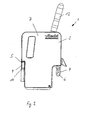
- FIG. 1 shows a mop press 1 for wringing liquid from a cleaning device with a housing 2, which consists essentially of two spaced-apart side walls 7, 8, between which a lever-operated wringer 3 is arranged.
- the wringer 3 comprises a lever 12, which opens into a shaft 13, wherein the shaft 13 is supported in the side cheeks 7, 8.
- Within the side cheeks 7, 8 is a gear arrangement via which the shaft 13 is connected to pressing jaws 14.
- These pressing jaws 14 are guided in a slot 15 and thereby describe a curved path during the pressing process.
- a rear-side fastening device 4 for attaching the mop press to a wiper bucket 16 or to a cleaning trolley 17 is arranged.
- the fastening device 4 consists of a hook-shaped projection 6 which is attached directly to the wringing device 3. To stiffen the projection 6 is provided with ribs. It is located on each page in Such a projection 6 is provided in close proximity to the side wall 7, 8.
- a support device 5 Provided on the housing 2 is a support device 5, which is spaced apart from the fastening device 4 in the horizontal direction.
- a laterally projecting projection 9 located on the housing 2 on the side opposite the fastening device 4 side on both sides in each case a laterally projecting projection 9, which projects beyond the housing 2 and the support means 5 forms.
- the projection 9 is formed by a cross bar 10, which projects beyond the housing 2 side.
- the cross bar 10 is of the same material and formed integrally with wringer 3 and is an integral part of this.
- FIG. 2 shows the in FIG. 1 Moppresse described in side view.
- FIG. 3 shows a mop press 1 for wringing liquid from a cleaning device with a housing 2, which consists essentially of two spaced-apart side walls 7, 8, between which a lever-operated wringer 3 is arranged.
- the wringer 3 comprises a lever 12, which opens into a shaft 13, wherein the shaft 13 is supported in the side cheeks 7, 8.
- Within the side cheeks 7, 8 is a gear arrangement via which the shaft 13 is connected to pressing jaws 14.
- These pressing jaws 14 are guided in a slot 15 and thereby describe a curved path during the pressing process.
- a rear-side fastening device 4 for attaching the mop press to a wiper bucket 16 or to a cleaning trolley 17 is arranged.
- the fastening device 4 consists of a hook-shaped projection 6 which is attached directly to the wringing device 3. To stiffen the projection 6 provided with ribs. In this case, there is on each side in the immediate vicinity of the side wall 7, 8 such a projection 6.
- a support means 5 is provided, which is spaced in the horizontal direction of the fastening means 4.
- the support means 5 is formed on the side cheeks 7, 8, each having a projection 11 which extends horizontally from the front to the back of the side cheeks 7, 8.
- FIG. 4 shows a cleaning system 16, comprising a mop bucket 17 with attached mop press 1 in the embodiment according to FIG. 1 , It can be seen that the projection 6 of the fastening device 4 surrounds the trailing edge of the wiper bucket 17 and the support device 5, formed by the cross bar 10, rests on the edge 18 of the wiper bucket 17.
- FIG. 5 shows a further cleaning system 19, comprising a cleaning trolley 20 with cross struts 21 to which the mop press 1 is attached. Under the mop press 1, a mop bucket 17 is positioned on the cleaning cart 20.
Landscapes
- Cleaning Implements For Floors, Carpets, Furniture, Walls, And The Like (AREA)
Abstract
Description
- Die Erfindung betrifft eine Moppresse zum Auswringen von Flüssigkeit aus einem Reinigungsgerät, umfassend ein Gehäuse mit einer hebelbetätigten Auswringvorrichtung, wobei das Gehäuse eine rückseitige Befestigungseinrichtung aufweist.
- Eine derartige Moppresse ist aus der
DE 20 2006 015 209 U1 bekannt. Die Moppresse dient zum Auspressen von Reinigungsflüssigkeit aus einem Reinigungsgerät, beispielsweise ein Flachwischer oder ein Wischmop. Die Auswringvorrichtung umfasst einen Hebel der über eine Welle mit Pressplatten in Wirkverbindung steht. Diese Pressplatten können sich je nach Ausführung in verschiedenen Richtungen bewegen und können auch in einer Kulisse und dadurch auch in einer Kurvenbahn geführt sein. Die Pressplatten legen sich an das Reinigungsgerät an und pressen den textilen Teil des Reinigungsgerätes an eine Gegenfläche, beispielsweise einem perforierten Auswringkorb. Derartige Moppressen werden meist gewerblich verwendet. Die Moppresse wird dabei entweder an einem Wischeimer oder an einem Reinigungswagen befestigt. Dazu weist die Moppresse eine rückseitige Befestigungseinrichtung auf, die beispielsweise aus einem hakenförmigen Vorsprung gebildet sein kann, der eine U-förmige Ausnehmung bildet, die mit dem Eimer oder dem Reinigungswagen zur Befestigung der Moppresse in Eingriff gelangt. Dabei ist die Kraft, die über den Hebel in die Auswringvorrichtung eingebracht werden kann, durch die Befestigung der Moppresse und dessen Gegenhalter beispielsweise die Eimerrückwand limitiert. Die üblichen Konstruktionen der Befestigungseinrichtung sieht die Aufnahme der beim Pressen entstehenden Kräfte und Drehmomente dadurch vor, dass ein erster horizontal verlaufender Gegenhalter, beispielsweise ein oberes Rohr oder der obere Eimerrand, mit der U-förmigen Ausnehmung an der Presse in Eingriff ist, während ein zweiter Gegenhalter, beispielsweise ein unteres Rohr oder die Fläche der Eimerrückwand, vertikal unterhalb davon in einem typischen Abstand von etwa 100 mm die Presse abstützt. Wird eine zu hohe Kraft über den Hebel eingebracht, kann sich die Moppresse aus der Befestigung lösen. - Der Erfindung liegt die Aufgabe zugrunde, eine Moppresse bereit zu stellen, die sich auch bei hohen Kräften sicher und stabil an einem Wischeimer oder Reinigungswagen abstützt.
- Diese Aufgabe wird mit den Merkmalen von Anspruch 1 gelöst. Auf vorteilhafte Ausgestaltungen nehmen die Unteransprüche Bezug.
- Zur Lösung der Aufgabe ist an dem Gehäuse eine Stützeinrichtung vorgesehen, die in horizontaler Richtung von der Befestigungseinrichtung beabstandet ist. Dabei hat die Stützeinrichtung einen größeren Abstand zu der Befestigungseinrichtung als bei der bekannten vertikalen Anordnung. Dieser Abstand ist bei der erfindungsgemäßen Ausgestaltung größer als 150 mm, wodurch das durch den Pressvorgang bedingte Drehmoment auf kleinere Abstützkräfte reduziert wird. Über die Stützeinrichtung wird ein Teil der in die Auswringvorrichtung eingebrachten Kraft abgeleitet. Da die Stützeinrichtung horizontal von der Befestigungseinrichtung entfernt ist, ergibt sich eine Abstützung der Moppresse an mehreren Punkten, so dass die Moppresse besonders stabil auf einem Wischeimer oder einem Reinigungswagen befestigt werden kann. Über den Hebel können hohe Kräfte in die Auswringvorrichtung eingebracht werden, die sicher über die Befestigungseinrichtung und die Stützeinrichtung übertragen werden, wodurch sich die Bedienbarkeit und die Auswringleistung verbessem. Die Stützeinrichtung kann dabei auch vertikal versetzt sein, wesentlich ist jedoch, dass die Stützeinrichtung zur Befestigungseinrichztung horizontal beabstandet ist.
- Die Befestigungseinrichtung kann aus einem hakenförmigen Vorsprung gebildet sein. Dadurch kann die Moppresse besonders einfach auf einem Wischeimer oder einem Reinigungswagen befestigt und auch wieder entnommen werden. Es ist lediglich erforderlich, die Moppresse einzuhängen.
- Das Gehäuse kann zwei Seitenwangen umfassen, zwischen denen die Auswringvorrichtung angeordnet ist. Die Seitenwangen schließen die Moppresse nach außen ab und bedecken Teile der Auswringvorrichtung oder nehmen Teile der Auswringvorrichtung auf, beispielsweise eine Kulisse oder eine Zahnradanordnung.
- Jede Seitenwange kann rückseitig eine Befestigungseinrichtung aufweisen. Dabei kann die Befestigungseinrichtung an die Seitenwangen angeformt und gemeinsam mit dieser hergestellt sein. Dadurch kann die Befestigungseinrichtung besonders einfach in die Moppresse integriert werden.
- Die Befestigungseinrichtung kann in die Auswringvorrichtung integriert sein. Dabei wird die Last, die über den Hebel direkt in die Auswringvorrichtung eingebracht wird, ohne Umwege direkt abgetragen.
- Das Gehäuse kann zumindest einen seitlich abragenden Vorsprung aufweisen, der das Gehäuse überragt und die Stützeinrichtung bildet. Dieser Vorsprung kann ebenfalls in die Seitenwange integriert und an diese angeformt sein. Der Vorsprung kann aber auch ein separates Bauteil sein. Da der Vorsprung an der der Befestigungseinrichtung gegenüber liegenden Seite angeordnet ist, ergibt sich bei einfacher Herstellbarkeit und Kompaktheit eine stabile Abstützung der Drehmomente aufgrund der großen Stützweite.
- An dem Gehäuse kann auf der der Befestigungseinrichtung gegenüber liegenden Seite ein Querriegel angeordnet sein, der das Gehäuse seitlich überragt und die Stützeinrichtung bildet. Der Querriegel kann ein separates Bauteil sein oder materialeinheitlich mit einem Bauteil der Moppresse ausgebildet sein. Der Querriegel kann einen rechteckigen Querschnitt aufweisen und kann besonders stabil ausgebildet sein, so dass eine sichere Abstützung der Moppresse gewährleistet ist.
- Die Seitenwangen können einen Vorsprung aufweisen, die die Stützeinrichtung bilden. Hierbei ist die Stützeinrichtung materialeinheitlich und einstückig mit der Seitenwange ausgebildet und kann dadurch besonders einfach hergestellt werden.
- Der Vorsprung kann sich von der Vorderseite bis zur Rückseite der Seitenwange erstrecken. Bei dieser Ausgestaltung erfolgt die Abstützung gleichmäßig längs der Seitenwange, so dass sich eine gleichmäßige Belastung des Wischeimers oder des Reinigungswagens ergibt.
- Die Stützeinrichtung kann an der Auswringvorrichtung angeordnet sein. Dabei wird die Last, die über den Hebel direkt in die Auswringvorrichtung eingebracht wird, ohne Umwege direkt abgetragen. Die Befestigungseinrichtung, die rückseitig an der Seitenwange angebracht ist, ist dann die einzige Einrichtung zur Kraftübertragung die in der Seitenwange angeordnet ist, so dass die Seitenwange nur an diesem Bereich entsprechend ausgelegt werden muss. Andere Bereiche der Seitenwange sind dann geringen Belastungen unterworfen und können dünnwandiger ausgelegt werden. Es ist auch denkbar, dass auch die Befestigungseinrichtung in die Auswringvorrichtung integriert ist. So erfolgt die Abstützung direkt und unmittelbar an der Auswringvorrichtung.
- Einige Ausführungsbeispiele der erfindungsgemäßen Moppresse werden nachfolgend anhand der Figuren näher erläutert. Diese zeigen, jeweils schematisch:
- Fig. 1
- eine Moppresse mit einem Querriegel;
- Fig. 2
- die Moppresse gemäß
Figur 1 in der Seitenansicht; - Fig. 3
- eine Moppresse mit durchgehenden in die Seitenwangen integrierten Vorsprüngen;
- Fig. 4
- ein Reinigungssystem bestehend aus Wischeimer und aufgesetzter Moppresse;
- Fig. 5
- ein weiteres Reinigungssystem bestehend aus einem Reinigungswagen mit daran befestigter Moppresse sowie einem unter der Moppresse positionierten Wischeimer.
-
Figur 1 zeigt eine Moppresse 1 zum Auswringen von Flüssigkeit aus einem Reinigungsgerät mit einem Gehäuse 2, welches im Wesentlichen aus zwei voneinander beabstandeten Seitenwangen 7, 8 besteht, zwischen denen eine hebelbetätigte Auswringvorrichtung 3 angeordnet ist. Die Auswringvorrichtung 3 umfasst einen Hebel 12, der in eine Welle 13 mündet, wobei die Welle 13 in den Seitenwangen 7, 8 abgestützt ist. Innerhalb der Seitenwangen 7, 8 befindet sich eine Zahnradanordnung über die die Welle 13 mit Pressbacken 14 verbunden ist. Diese Pressbacken 14 sind in einer Kulisse 15 geführt und beschreiben dadurch beim Pressvorgang eine Kurvenbahn. In das Gehäuse 2 ist eine rückseitige Befestigungseinrichtung 4 zur Befestigung der Moppresse an einem Wischeimer 16 oder an einem Reinigungswagen 17 angeordnet. Die Befestigungseinrichtung 4 besteht aus einem hakenförmigen Vorsprung 6 der unmittelbar an der Auswringvorrichtung 3 befestigt ist. Zur Versteifung ist der Vorsprung 6 mit Rippen versehen. Dabei befindet sich auf jeder Seite in unmittelbarer Nähe zur Seitenwange 7, 8 ein derartiger Vorsprung 6. An dem Gehäuse 2 ist eine Stützeinrichtung 5 vorgesehen, die in horizontaler Richtung von der Befestigungseinrichtung 4 beabstandet ist. Dazu befindet sich an dem Gehäuse 2 an der der Befestigungseinrichtung 4 gegenüber liegenden Seite beidseitig jeweils ein seitlich abragender Vorsprung 9, der das Gehäuse 2 überragt und die Stützeinrichtung 5 bildet. In dieser Ausführung ist der Vorsprung 9 durch einen Querriegel 10 gebildet, der das Gehäuse 2 seitlich überragt. Der Querriegel 10 ist materialeinheitlich und einstückig mit Auswringvorrichtung 3 ausgebildet und ist ein integraler Bestandteil dieser. -
Figur 2 zeigt die inFigur 1 beschriebene Moppresse in der Seitenansicht. -
Figur 3 zeigt eine Moppresse 1 zum Auswringen von Flüssigkeit aus einem Reinigungsgerät mit einem Gehäuse 2, welches im Wesentlichen aus zwei voneinander beabstandeten Seitenwangen 7, 8 besteht, zwischen denen eine hebelbetätigte Auswringvorrichtung 3 angeordnet ist. Die Auswringvorrichtung 3 umfasst einen Hebel 12, der in eine Welle 13 mündet, wobei die Welle 13 in den Seitenwangen 7, 8 abgestützt ist. Innerhalb der Seitenwangen 7, 8 befindet sich eine Zahnradanordnung über die die Welle 13 mit Pressbacken 14 verbunden ist. Diese Pressbacken 14 sind in einer Kulisse 15 geführt und beschreiben dadurch beim Pressvorgang eine Kurvenbahn. In das Gehäuse 2 ist eine rückseitige Befestigungseinrichtung 4 zur Befestigung der Moppresse an einem Wischeimer 16 oder an einem Reinigungswagen 17 angeordnet. Die Befestigungseinrichtung 4 besteht aus einem hakenförmigen Vorsprung 6 der unmittelbar an der Auswringvorrichtung 3 befestigt ist. Zur Versteifung der Vorsprung 6 mit Rippen versehen. Dabei befindet sich auf jeder Seite in unmittelbarer Nähe zur Seitenwange 7, 8 ein derartiger Vorsprung 6. An dem Gehäuse 2 ist eine Stützeinrichtung 5 vorgesehen, die in horizontaler Richtung von der Befestigungseinrichtung 4 beabstandet ist. In dieser Ausgestaltung ist die Stützeinrichtung 5 an den Seitenwangen 7, 8 ausgebildet, die dazu jeweils einen Vorsprung 11 aufweisen, der sich horizontal von der Vorderseite bis zur Rückseite der Seitenwangen 7, 8 erstreckt. -
Figur 4 zeigt ein Reinigungssystem 16, umfassend einen Wischeimer 17 mit aufgesetzter Moppresse 1 in der Ausgestaltung gemäßFigur 1 . Es ist zu erkennen, dass der Vorsprung 6 der Befestigungseinrichtung 4 die Hinterkante des Wischeimers 17 umgreift und die Stützeinrichtung 5, gebildet durch den Querriegel 10, auf der Kante 18 des Wischeimers 17 aufliegt. -
Figur 5 zeigt ein weiteres Reinigungssystem 19, umfassend einen Reinigungswagen 20 mit Querstreben 21 an denen die Moppresse 1 befestigt ist. Unter der Moppresse 1 ist ein Wischeimer 17 auf dem Reinigungswagen 20 positioniert.
Claims (3)
- Moppresse (1) zum Auswringen von Flüssigkeit aus einem Reinigungsgerät, umfassend ein Gehäuse (2) mit einer hebelbetätigten Auswringvorrichtung (3), wobei das Gehäuse (2) eine rückseitige Befesfigungseinrichtung (4) aufweist, dadurch gekennzeichnet, dass an dem Gehäuse (2) eine Stützeinrichtung (5) vorgesehen, ist, die in horizontaler Richtung von der Befestigungseinrichtung (4) beabstandet ist,
- Moppresse nach Anspruch 1 dadurch gekennzeichnet, 2. dass das Gehäuse (2) zumindest einen seitlich abragenden Vorsprung (9) aufweist, der das Gehäuse (2) überragt und die Stützeinrichtung (5) bildet.
- Moppresse nach einem der Ansprüche 1 order 2 dadurchgekennzeichnet, dass an dem Gehäuse (2) auf der der Befestigungseinrichtung (4) gegenüber liegenden Seite ein Querriegel (10) angeordnet ist, der das Gehäuse (2) seitlich überragt und die Stützeinrichtung (5) bildet
Applications Claiming Priority (2)
| Application Number | Priority Date | Filing Date | Title |
|---|---|---|---|
| DE102008022364A DE102008022364A1 (de) | 2008-05-06 | 2008-05-06 | Moppresse |
| EP09741813A EP2271244A2 (de) | 2008-05-06 | 2009-04-24 | Moppresse |
Related Parent Applications (2)
| Application Number | Title | Priority Date | Filing Date |
|---|---|---|---|
| EP09741813.1 Division | 2009-04-24 | ||
| WOPCT/EP2009/002998 Previously-Filed-Application | 2009-04-24 |
Publications (2)
| Publication Number | Publication Date |
|---|---|
| EP2316326A1 true EP2316326A1 (de) | 2011-05-04 |
| EP2316326B1 EP2316326B1 (de) | 2013-11-06 |
Family
ID=40874925
Family Applications (3)
| Application Number | Title | Priority Date | Filing Date |
|---|---|---|---|
| EP10014020A Ceased EP2316325A1 (de) | 2008-05-06 | 2009-04-24 | Moppresse |
| EP09741813A Withdrawn EP2271244A2 (de) | 2008-05-06 | 2009-04-24 | Moppresse |
| EP10014015.1A Not-in-force EP2316326B1 (de) | 2008-05-06 | 2009-04-24 | Reinigungssystem |
Family Applications Before (2)
| Application Number | Title | Priority Date | Filing Date |
|---|---|---|---|
| EP10014020A Ceased EP2316325A1 (de) | 2008-05-06 | 2009-04-24 | Moppresse |
| EP09741813A Withdrawn EP2271244A2 (de) | 2008-05-06 | 2009-04-24 | Moppresse |
Country Status (7)
| Country | Link |
|---|---|
| US (1) | US8689391B2 (de) |
| EP (3) | EP2316325A1 (de) |
| CA (1) | CA2723750C (de) |
| DE (1) | DE102008022364A1 (de) |
| ES (1) | ES2444944T3 (de) |
| RU (1) | RU2441568C1 (de) |
| WO (1) | WO2009135594A2 (de) |
Families Citing this family (2)
| Publication number | Priority date | Publication date | Assignee | Title |
|---|---|---|---|---|
| USD756582S1 (en) | 2014-11-11 | 2016-05-17 | The Libman Company | Mop bucket |
| RU195203U1 (ru) * | 2019-09-20 | 2020-01-17 | Андрей Витальевич Кибец | Отжимное устройство для моющих насадок. |
Citations (5)
| Publication number | Priority date | Publication date | Assignee | Title |
|---|---|---|---|---|
| EP0734681A1 (de) * | 1995-03-03 | 1996-10-02 | Yugengaisha Access | Wischer-Auswringevorrichtung |
| US20020120997A1 (en) * | 2001-01-30 | 2002-09-05 | Alt Steven J. | Mop bucket with mop wringer attachment |
| WO2005117680A1 (de) * | 2004-05-28 | 2005-12-15 | Carl Freudenberg Kg | Wischsystem, auswringvorrichtung und wischgerät |
| EP1627591A2 (de) * | 2004-08-16 | 2006-02-22 | Ronald Alexander Young | Vorrichtung zum Auspressen von Wischgeräten und Adapter |
| DE202006015209U1 (de) | 2006-10-05 | 2006-12-28 | Meiko Textil Gmbh | Vorrichtung zum Auspressen eines Nasswischbezugs auf einem Wischbezugshalter |
Family Cites Families (11)
| Publication number | Priority date | Publication date | Assignee | Title |
|---|---|---|---|---|
| US572073A (en) * | 1896-11-24 | Island | ||
| US5333353A (en) * | 1990-02-13 | 1994-08-02 | Scot Young Research Limited | Mop wringers and buckets |
| GB9003175D0 (en) * | 1990-02-13 | 1990-04-11 | Brute Ltd | Mop wringers and buckets |
| US5983441A (en) * | 1997-05-29 | 1999-11-16 | S. C. Johnson Commercial Markets, Inc. | Bucket insert and wash bucket |
| CA2283539A1 (en) * | 1998-09-24 | 2000-03-24 | Robert S. Robinson | Ergonomic, liquid-transport container |
| GB2352388B (en) | 1999-07-26 | 2001-07-04 | Numatic Int Ltd | Improvements to mop presses |
| DE20117581U1 (de) * | 2001-10-24 | 2002-01-24 | Kaul, Friedrich, 90411 Nürnberg | Ausdrückvorrichtung |
| US20050204503A1 (en) * | 2004-03-19 | 2005-09-22 | Burns Thomas D | Filtered wringer |
| US20060085939A1 (en) * | 2004-10-21 | 2006-04-27 | Petner Robert E | Combination mop wringer and bucket system |
| US20060213021A1 (en) | 2005-03-22 | 2006-09-28 | Ducharme Raymond E | Mop wringer and handle stabilizer |
| US8627541B2 (en) | 2005-10-19 | 2014-01-14 | Unger Marketing International, Llc | Mop press having top and bottom cam tracks |
-
2008
- 2008-05-06 DE DE102008022364A patent/DE102008022364A1/de not_active Ceased
-
2009
- 2009-04-24 RU RU2010149838/12A patent/RU2441568C1/ru not_active IP Right Cessation
- 2009-04-24 EP EP10014020A patent/EP2316325A1/de not_active Ceased
- 2009-04-24 EP EP09741813A patent/EP2271244A2/de not_active Withdrawn
- 2009-04-24 WO PCT/EP2009/002998 patent/WO2009135594A2/de not_active Ceased
- 2009-04-24 US US12/990,967 patent/US8689391B2/en not_active Expired - Fee Related
- 2009-04-24 CA CA2723750A patent/CA2723750C/en not_active Expired - Fee Related
- 2009-04-24 EP EP10014015.1A patent/EP2316326B1/de not_active Not-in-force
- 2009-04-24 ES ES10014015.1T patent/ES2444944T3/es active Active
Patent Citations (5)
| Publication number | Priority date | Publication date | Assignee | Title |
|---|---|---|---|---|
| EP0734681A1 (de) * | 1995-03-03 | 1996-10-02 | Yugengaisha Access | Wischer-Auswringevorrichtung |
| US20020120997A1 (en) * | 2001-01-30 | 2002-09-05 | Alt Steven J. | Mop bucket with mop wringer attachment |
| WO2005117680A1 (de) * | 2004-05-28 | 2005-12-15 | Carl Freudenberg Kg | Wischsystem, auswringvorrichtung und wischgerät |
| EP1627591A2 (de) * | 2004-08-16 | 2006-02-22 | Ronald Alexander Young | Vorrichtung zum Auspressen von Wischgeräten und Adapter |
| DE202006015209U1 (de) | 2006-10-05 | 2006-12-28 | Meiko Textil Gmbh | Vorrichtung zum Auspressen eines Nasswischbezugs auf einem Wischbezugshalter |
Also Published As
| Publication number | Publication date |
|---|---|
| RU2441568C1 (ru) | 2012-02-10 |
| WO2009135594A3 (de) | 2010-03-11 |
| EP2316326B1 (de) | 2013-11-06 |
| CA2723750A1 (en) | 2009-11-12 |
| WO2009135594A2 (de) | 2009-11-12 |
| CA2723750C (en) | 2013-10-29 |
| DE102008022364A1 (de) | 2009-11-12 |
| ES2444944T3 (es) | 2014-02-27 |
| EP2271244A2 (de) | 2011-01-12 |
| US8689391B2 (en) | 2014-04-08 |
| EP2316325A1 (de) | 2011-05-04 |
| US20110056043A1 (en) | 2011-03-10 |
Similar Documents
| Publication | Publication Date | Title |
|---|---|---|
| WO2016165992A1 (de) | LÖSBARE BEFESTIGUNGSANORDNUNG EINES STOßFÄNGERS MIT EINER SEITENWAND BZW. EINEM KOTFLÜGEL EINES KRAFTFAHRZEUGES | |
| EP3077133A1 (de) | Biegepresse | |
| DE19823424B4 (de) | Gerätegehäuse, insbesondere für Haushaltsgroßgeräte | |
| EP2316326B1 (de) | Reinigungssystem | |
| DE102011005211A1 (de) | Handreiniger für glatte Flächen | |
| EP2397601B1 (de) | Traverse für ein Haushaltsgerät, Baugruppe für den Zusammenbau eines Haushaltgeräts, und Haushaltgerät | |
| DE102007024606B4 (de) | Entwässerungsvorrichtung | |
| DE2455521C3 (de) | Hydraulische Blechbiegepresse | |
| EP1342445B1 (de) | Wischgerät | |
| DE102014101464A1 (de) | Befestigungseinrichtung | |
| EP2128046A1 (de) | Befestigungselement für eine Rollenleiste und Durchlaufregal | |
| DE102020204845A1 (de) | Indirekter Ladeluftkühler | |
| EP2425150A1 (de) | Vorrichtung zum verbinden von wenigstens zwei gurten | |
| DE102004026837B4 (de) | Wischsystem, Auswringvorrichtung und Wischgerät | |
| WO2001067941A1 (de) | Wischvorrichtung, auspressvorrichtung und wischsystem | |
| EP3129533A1 (de) | Fixkamm für eine kämmmaschine | |
| DE102012205577B3 (de) | Horizontalrührwerk | |
| EP2684696B1 (de) | Universaladapter zur Verbindung von Schablonen verschiedener Spannsysteme mit demselben Spannrahmen | |
| DE2628537B2 (de) | Tragelement | |
| EP1561954B1 (de) | Verbindungselement zum lösbaren Verbinden von sich teilweise überlappenden Teilen sowie ein derartige Verbindungselemente aufweisendes Gehäuse und ein Verfahren zum lösbaren Verbinden von sich wenigstens teilweise überlappenden Teilen | |
| EP0951113B1 (de) | Rechteckiges Gehäuse zur Aufnahme elektrischer oder eletronischer Bauteile | |
| DE202008001305U1 (de) | Strebe für ein Gestell | |
| DE2530914C2 (de) | Plangestell | |
| DE1782188B2 (de) | Gestell fuer schichtenfilter | |
| DE2412506C3 (de) | Kastenförmiger Hohlträger an einer Kraftwagenkarosserle |
Legal Events
| Date | Code | Title | Description |
|---|---|---|---|
| PUAI | Public reference made under article 153(3) epc to a published international application that has entered the european phase |
Free format text: ORIGINAL CODE: 0009012 |
|
| 17P | Request for examination filed |
Effective date: 20101027 |
|
| AC | Divisional application: reference to earlier application |
Ref document number: 2271244 Country of ref document: EP Kind code of ref document: P |
|
| AK | Designated contracting states |
Kind code of ref document: A1 Designated state(s): AT BE BG CH CY CZ DE DK EE ES FI FR GB GR HR HU IE IS IT LI LT LU LV MC MK MT NL NO PL PT RO SE SI SK TR |
|
| AX | Request for extension of the european patent |
Extension state: AL BA RS |
|
| 17Q | First examination report despatched |
Effective date: 20121207 |
|
| GRAP | Despatch of communication of intention to grant a patent |
Free format text: ORIGINAL CODE: EPIDOSNIGR1 |
|
| INTG | Intention to grant announced |
Effective date: 20130717 |
|
| GRAS | Grant fee paid |
Free format text: ORIGINAL CODE: EPIDOSNIGR3 |
|
| GRAA | (expected) grant |
Free format text: ORIGINAL CODE: 0009210 |
|
| AC | Divisional application: reference to earlier application |
Ref document number: 2271244 Country of ref document: EP Kind code of ref document: P |
|
| AK | Designated contracting states |
Kind code of ref document: B1 Designated state(s): AT BE BG CH CY CZ DE DK EE ES FI FR GB GR HR HU IE IS IT LI LT LU LV MC MK MT NL NO PL PT RO SE SI SK TR |
|
| REG | Reference to a national code |
Ref country code: GB Ref legal event code: FG4D Free format text: NOT ENGLISH |
|
| REG | Reference to a national code |
Ref country code: CH Ref legal event code: EP |
|
| REG | Reference to a national code |
Ref country code: AT Ref legal event code: REF Ref document number: 638844 Country of ref document: AT Kind code of ref document: T Effective date: 20131215 |
|
| REG | Reference to a national code |
Ref country code: IE Ref legal event code: FG4D Free format text: LANGUAGE OF EP DOCUMENT: GERMAN |
|
| REG | Reference to a national code |
Ref country code: DE Ref legal event code: R096 Ref document number: 502009008316 Country of ref document: DE Effective date: 20140102 |
|
| REG | Reference to a national code |
Ref country code: ES Ref legal event code: FG2A Ref document number: 2444944 Country of ref document: ES Kind code of ref document: T3 Effective date: 20140227 |
|
| REG | Reference to a national code |
Ref country code: NL Ref legal event code: VDEP Effective date: 20131106 |
|
| REG | Reference to a national code |
Ref country code: LT Ref legal event code: MG4D |
|
| PG25 | Lapsed in a contracting state [announced via postgrant information from national office to epo] |
Ref country code: FI Free format text: LAPSE BECAUSE OF FAILURE TO SUBMIT A TRANSLATION OF THE DESCRIPTION OR TO PAY THE FEE WITHIN THE PRESCRIBED TIME-LIMIT Effective date: 20131106 Ref country code: NL Free format text: LAPSE BECAUSE OF FAILURE TO SUBMIT A TRANSLATION OF THE DESCRIPTION OR TO PAY THE FEE WITHIN THE PRESCRIBED TIME-LIMIT Effective date: 20131106 Ref country code: NO Free format text: LAPSE BECAUSE OF FAILURE TO SUBMIT A TRANSLATION OF THE DESCRIPTION OR TO PAY THE FEE WITHIN THE PRESCRIBED TIME-LIMIT Effective date: 20140206 Ref country code: HR Free format text: LAPSE BECAUSE OF FAILURE TO SUBMIT A TRANSLATION OF THE DESCRIPTION OR TO PAY THE FEE WITHIN THE PRESCRIBED TIME-LIMIT Effective date: 20131106 Ref country code: LT Free format text: LAPSE BECAUSE OF FAILURE TO SUBMIT A TRANSLATION OF THE DESCRIPTION OR TO PAY THE FEE WITHIN THE PRESCRIBED TIME-LIMIT Effective date: 20131106 Ref country code: IS Free format text: LAPSE BECAUSE OF FAILURE TO SUBMIT A TRANSLATION OF THE DESCRIPTION OR TO PAY THE FEE WITHIN THE PRESCRIBED TIME-LIMIT Effective date: 20140306 Ref country code: SE Free format text: LAPSE BECAUSE OF FAILURE TO SUBMIT A TRANSLATION OF THE DESCRIPTION OR TO PAY THE FEE WITHIN THE PRESCRIBED TIME-LIMIT Effective date: 20131106 |
|
| PG25 | Lapsed in a contracting state [announced via postgrant information from national office to epo] |
Ref country code: LV Free format text: LAPSE BECAUSE OF FAILURE TO SUBMIT A TRANSLATION OF THE DESCRIPTION OR TO PAY THE FEE WITHIN THE PRESCRIBED TIME-LIMIT Effective date: 20131106 |
|
| PG25 | Lapsed in a contracting state [announced via postgrant information from national office to epo] |
Ref country code: PT Free format text: LAPSE BECAUSE OF FAILURE TO SUBMIT A TRANSLATION OF THE DESCRIPTION OR TO PAY THE FEE WITHIN THE PRESCRIBED TIME-LIMIT Effective date: 20140306 |
|
| PG25 | Lapsed in a contracting state [announced via postgrant information from national office to epo] |
Ref country code: EE Free format text: LAPSE BECAUSE OF FAILURE TO SUBMIT A TRANSLATION OF THE DESCRIPTION OR TO PAY THE FEE WITHIN THE PRESCRIBED TIME-LIMIT Effective date: 20131106 |
|
| REG | Reference to a national code |
Ref country code: DE Ref legal event code: R097 Ref document number: 502009008316 Country of ref document: DE |
|
| PG25 | Lapsed in a contracting state [announced via postgrant information from national office to epo] |
Ref country code: CZ Free format text: LAPSE BECAUSE OF FAILURE TO SUBMIT A TRANSLATION OF THE DESCRIPTION OR TO PAY THE FEE WITHIN THE PRESCRIBED TIME-LIMIT Effective date: 20131106 Ref country code: SK Free format text: LAPSE BECAUSE OF FAILURE TO SUBMIT A TRANSLATION OF THE DESCRIPTION OR TO PAY THE FEE WITHIN THE PRESCRIBED TIME-LIMIT Effective date: 20131106 Ref country code: PL Free format text: LAPSE BECAUSE OF FAILURE TO SUBMIT A TRANSLATION OF THE DESCRIPTION OR TO PAY THE FEE WITHIN THE PRESCRIBED TIME-LIMIT Effective date: 20131106 Ref country code: RO Free format text: LAPSE BECAUSE OF FAILURE TO SUBMIT A TRANSLATION OF THE DESCRIPTION OR TO PAY THE FEE WITHIN THE PRESCRIBED TIME-LIMIT Effective date: 20131106 |
|
| PLBE | No opposition filed within time limit |
Free format text: ORIGINAL CODE: 0009261 |
|
| STAA | Information on the status of an ep patent application or granted ep patent |
Free format text: STATUS: NO OPPOSITION FILED WITHIN TIME LIMIT |
|
| PG25 | Lapsed in a contracting state [announced via postgrant information from national office to epo] |
Ref country code: DK Free format text: LAPSE BECAUSE OF FAILURE TO SUBMIT A TRANSLATION OF THE DESCRIPTION OR TO PAY THE FEE WITHIN THE PRESCRIBED TIME-LIMIT Effective date: 20131106 |
|
| 26N | No opposition filed |
Effective date: 20140807 |
|
| REG | Reference to a national code |
Ref country code: DE Ref legal event code: R097 Ref document number: 502009008316 Country of ref document: DE Effective date: 20140807 |
|
| PG25 | Lapsed in a contracting state [announced via postgrant information from national office to epo] |
Ref country code: LU Free format text: LAPSE BECAUSE OF FAILURE TO SUBMIT A TRANSLATION OF THE DESCRIPTION OR TO PAY THE FEE WITHIN THE PRESCRIBED TIME-LIMIT Effective date: 20140424 Ref country code: MC Free format text: LAPSE BECAUSE OF FAILURE TO SUBMIT A TRANSLATION OF THE DESCRIPTION OR TO PAY THE FEE WITHIN THE PRESCRIBED TIME-LIMIT Effective date: 20131106 |
|
| REG | Reference to a national code |
Ref country code: CH Ref legal event code: PL |
|
| GBPC | Gb: european patent ceased through non-payment of renewal fee |
Effective date: 20140424 |
|
| REG | Reference to a national code |
Ref country code: FR Ref legal event code: ST Effective date: 20141231 |
|
| REG | Reference to a national code |
Ref country code: IE Ref legal event code: MM4A |
|
| PG25 | Lapsed in a contracting state [announced via postgrant information from national office to epo] |
Ref country code: GB Free format text: LAPSE BECAUSE OF NON-PAYMENT OF DUE FEES Effective date: 20140424 Ref country code: LI Free format text: LAPSE BECAUSE OF NON-PAYMENT OF DUE FEES Effective date: 20140430 Ref country code: CH Free format text: LAPSE BECAUSE OF NON-PAYMENT OF DUE FEES Effective date: 20140430 |
|
| PG25 | Lapsed in a contracting state [announced via postgrant information from national office to epo] |
Ref country code: SI Free format text: LAPSE BECAUSE OF FAILURE TO SUBMIT A TRANSLATION OF THE DESCRIPTION OR TO PAY THE FEE WITHIN THE PRESCRIBED TIME-LIMIT Effective date: 20131106 Ref country code: FR Free format text: LAPSE BECAUSE OF NON-PAYMENT OF DUE FEES Effective date: 20140430 |
|
| PG25 | Lapsed in a contracting state [announced via postgrant information from national office to epo] |
Ref country code: IE Free format text: LAPSE BECAUSE OF NON-PAYMENT OF DUE FEES Effective date: 20140424 |
|
| REG | Reference to a national code |
Ref country code: AT Ref legal event code: MM01 Ref document number: 638844 Country of ref document: AT Kind code of ref document: T Effective date: 20140424 |
|
| PG25 | Lapsed in a contracting state [announced via postgrant information from national office to epo] |
Ref country code: AT Free format text: LAPSE BECAUSE OF NON-PAYMENT OF DUE FEES Effective date: 20140424 |
|
| PG25 | Lapsed in a contracting state [announced via postgrant information from national office to epo] |
Ref country code: MT Free format text: LAPSE BECAUSE OF FAILURE TO SUBMIT A TRANSLATION OF THE DESCRIPTION OR TO PAY THE FEE WITHIN THE PRESCRIBED TIME-LIMIT Effective date: 20131106 |
|
| PG25 | Lapsed in a contracting state [announced via postgrant information from national office to epo] |
Ref country code: CY Free format text: LAPSE BECAUSE OF FAILURE TO SUBMIT A TRANSLATION OF THE DESCRIPTION OR TO PAY THE FEE WITHIN THE PRESCRIBED TIME-LIMIT Effective date: 20131106 Ref country code: BG Free format text: LAPSE BECAUSE OF FAILURE TO SUBMIT A TRANSLATION OF THE DESCRIPTION OR TO PAY THE FEE WITHIN THE PRESCRIBED TIME-LIMIT Effective date: 20131106 Ref country code: GR Free format text: LAPSE BECAUSE OF FAILURE TO SUBMIT A TRANSLATION OF THE DESCRIPTION OR TO PAY THE FEE WITHIN THE PRESCRIBED TIME-LIMIT Effective date: 20140207 |
|
| PG25 | Lapsed in a contracting state [announced via postgrant information from national office to epo] |
Ref country code: HU Free format text: LAPSE BECAUSE OF FAILURE TO SUBMIT A TRANSLATION OF THE DESCRIPTION OR TO PAY THE FEE WITHIN THE PRESCRIBED TIME-LIMIT; INVALID AB INITIO Effective date: 20090424 Ref country code: TR Free format text: LAPSE BECAUSE OF FAILURE TO SUBMIT A TRANSLATION OF THE DESCRIPTION OR TO PAY THE FEE WITHIN THE PRESCRIBED TIME-LIMIT Effective date: 20131106 Ref country code: BE Free format text: LAPSE BECAUSE OF FAILURE TO SUBMIT A TRANSLATION OF THE DESCRIPTION OR TO PAY THE FEE WITHIN THE PRESCRIBED TIME-LIMIT Effective date: 20140430 |
|
| PGFP | Annual fee paid to national office [announced via postgrant information from national office to epo] |
Ref country code: ES Payment date: 20160422 Year of fee payment: 8 Ref country code: DE Payment date: 20160426 Year of fee payment: 8 |
|
| PGFP | Annual fee paid to national office [announced via postgrant information from national office to epo] |
Ref country code: IT Payment date: 20160429 Year of fee payment: 8 |
|
| REG | Reference to a national code |
Ref country code: DE Ref legal event code: R119 Ref document number: 502009008316 Country of ref document: DE |
|
| PG25 | Lapsed in a contracting state [announced via postgrant information from national office to epo] |
Ref country code: DE Free format text: LAPSE BECAUSE OF NON-PAYMENT OF DUE FEES Effective date: 20171103 |
|
| PG25 | Lapsed in a contracting state [announced via postgrant information from national office to epo] |
Ref country code: IT Free format text: LAPSE BECAUSE OF NON-PAYMENT OF DUE FEES Effective date: 20170424 |
|
| PG25 | Lapsed in a contracting state [announced via postgrant information from national office to epo] |
Ref country code: MK Free format text: LAPSE BECAUSE OF FAILURE TO SUBMIT A TRANSLATION OF THE DESCRIPTION OR TO PAY THE FEE WITHIN THE PRESCRIBED TIME-LIMIT Effective date: 20131106 |
|
| REG | Reference to a national code |
Ref country code: ES Ref legal event code: FD2A Effective date: 20180706 |
|
| PG25 | Lapsed in a contracting state [announced via postgrant information from national office to epo] |
Ref country code: ES Free format text: LAPSE BECAUSE OF NON-PAYMENT OF DUE FEES Effective date: 20170425 |