EP2316019B1 - Ultraschallprüfkopf - Google Patents
Ultraschallprüfkopf Download PDFInfo
- Publication number
- EP2316019B1 EP2316019B1 EP09781889A EP09781889A EP2316019B1 EP 2316019 B1 EP2316019 B1 EP 2316019B1 EP 09781889 A EP09781889 A EP 09781889A EP 09781889 A EP09781889 A EP 09781889A EP 2316019 B1 EP2316019 B1 EP 2316019B1
- Authority
- EP
- European Patent Office
- Prior art keywords
- edge
- ultrasonic probe
- probe
- ultrasonic
- holder
- Prior art date
- Legal status (The legal status is an assumption and is not a legal conclusion. Google has not performed a legal analysis and makes no representation as to the accuracy of the status listed.)
- Not-in-force
Links
- 239000000523 sample Substances 0.000 title claims description 55
- 239000000463 material Substances 0.000 claims abstract description 10
- 230000008878 coupling Effects 0.000 claims description 15
- 238000010168 coupling process Methods 0.000 claims description 15
- 238000005859 coupling reaction Methods 0.000 claims description 15
- 238000007789 sealing Methods 0.000 claims description 14
- 238000012360 testing method Methods 0.000 abstract description 47
- 238000002604 ultrasonography Methods 0.000 abstract description 14
- 239000007822 coupling agent Substances 0.000 description 24
- 238000000034 method Methods 0.000 description 4
- 238000011161 development Methods 0.000 description 3
- 230000018109 developmental process Effects 0.000 description 3
- 238000005516 engineering process Methods 0.000 description 2
- 230000000694 effects Effects 0.000 description 1
- 239000007788 liquid Substances 0.000 description 1
- 238000011089 mechanical engineering Methods 0.000 description 1
- 230000035515 penetration Effects 0.000 description 1
- 230000035945 sensitivity Effects 0.000 description 1
- XLYOFNOQVPJJNP-UHFFFAOYSA-N water Substances O XLYOFNOQVPJJNP-UHFFFAOYSA-N 0.000 description 1
Images

Classifications
-
- G—PHYSICS
- G01—MEASURING; TESTING
- G01N—INVESTIGATING OR ANALYSING MATERIALS BY DETERMINING THEIR CHEMICAL OR PHYSICAL PROPERTIES
- G01N29/00—Investigating or analysing materials by the use of ultrasonic, sonic or infrasonic waves; Visualisation of the interior of objects by transmitting ultrasonic or sonic waves through the object
- G01N29/22—Details, e.g. general constructional or apparatus details
- G01N29/28—Details, e.g. general constructional or apparatus details providing acoustic coupling, e.g. water
-
- G—PHYSICS
- G01—MEASURING; TESTING
- G01N—INVESTIGATING OR ANALYSING MATERIALS BY DETERMINING THEIR CHEMICAL OR PHYSICAL PROPERTIES
- G01N29/00—Investigating or analysing materials by the use of ultrasonic, sonic or infrasonic waves; Visualisation of the interior of objects by transmitting ultrasonic or sonic waves through the object
- G01N29/22—Details, e.g. general constructional or apparatus details
- G01N29/24—Probes
- G01N29/2437—Piezoelectric probes
-
- G—PHYSICS
- G01—MEASURING; TESTING
- G01N—INVESTIGATING OR ANALYSING MATERIALS BY DETERMINING THEIR CHEMICAL OR PHYSICAL PROPERTIES
- G01N29/00—Investigating or analysing materials by the use of ultrasonic, sonic or infrasonic waves; Visualisation of the interior of objects by transmitting ultrasonic or sonic waves through the object
- G01N29/22—Details, e.g. general constructional or apparatus details
- G01N29/26—Arrangements for orientation or scanning by relative movement of the head and the sensor
- G01N29/265—Arrangements for orientation or scanning by relative movement of the head and the sensor by moving the sensor relative to a stationary material
-
- G—PHYSICS
- G01—MEASURING; TESTING
- G01N—INVESTIGATING OR ANALYSING MATERIALS BY DETERMINING THEIR CHEMICAL OR PHYSICAL PROPERTIES
- G01N2291/00—Indexing codes associated with group G01N29/00
- G01N2291/10—Number of transducers
- G01N2291/101—Number of transducers one transducer
-
- G—PHYSICS
- G01—MEASURING; TESTING
- G01N—INVESTIGATING OR ANALYSING MATERIALS BY DETERMINING THEIR CHEMICAL OR PHYSICAL PROPERTIES
- G01N2291/00—Indexing codes associated with group G01N29/00
- G01N2291/26—Scanned objects
- G01N2291/263—Surfaces
Definitions
- the invention relates to an ultrasound probe comprising an ultrasound probe surface bounded by an edge.
- Such Ultraschallpröfkexcellent are off US 4,033,178 and US 5 567 881 known.
- the ultrasonic testing technique is used in many areas of mechanical engineering, for example, to find discontinuities in rotors of steam turbines, gas turbines or generators.
- Ultrasound technology has proven itself as a reliable testing technique.
- Ultrasonic testing technology uses conventional probes as well as phased array probes. For a good test result it is important that the ultrasonic test head is ultrasonically connected to the surface of the test object. This ensures penetration of the ultrasonic wave into the test subject.
- An ultrasonic probe comprises an ultrasonic probe surface from which the ultrasonic waves are emitted. So that the ultrasonic waves can penetrate well into the test object, usually a coupling agent between the Ultraschallprüfkopf preparation and the Früfussistand is arranged. This coupling agent may be, for example, water or a gel.
- sealing tapes are arranged in turbines such that so-called sealing lips protrude from a surface.
- An ultrasonic probe should be coupled as close as possible to this surface.
- the sealing tapes prevent direct coupling to the surface to be tested.
- the sealing tapes are caulked in grooves. If a rotor provided with sealing tapes is to be tested ultrasonically, the sealing tapes are currently being pulled out of the grooves.
- there is self With drawn sealing tapes the problem that there is not enough coupling agent between the rotor and the ultrasonic probe. It may be that the coupling agent disappears in the free grooves and a good coupling of the probe to the test surface is not possible.
- the invention begins, whose task is to improve the coupling of an ultrasonic probe on a surface to be tested.
- an ultrasound probe comprising an ultrasound probe surface bounded by an edge, a probe holder being disposed about the ultrasound probe along the rim, the probe holder projecting beyond the ultrasound probe surface.
- the invention is based inter alia on the idea that the ultrasonic probe is limited by an edge and that a coupling agent between the Ultraschallprüfkopf preparation and the surface to be tested has the ability to escape the side of the ultrasonic probe.
- the invention therefore proposes to arrange a test head holder around the edge of the ultrasonic test head, which prevents the coupling means from escaping.
- the educaticianhalterung should therefore so on the Out edge that a contact between the surface and the probe holder is formed. A movement of the ultrasonic probe along the surface to be tested is now easily possible, since the coupling means between the ultrasonic probe head surface and the surface to be tested by the fürkopfhalterung is pulled.
- test head holder acts as a windscreen wiper, so to speak.
- the Tecrkopfhalterung is formed such that it forms a flexible frame which serves as a retaining device for the coupling means. Damage to the test head or of attachment parts by burrs is thereby effectively avoided, as a more even coupling is ensured and the ultrasonic signals are improved during ultrasonic testing. In addition to the considerable time savings during an ultrasonic test, an improved test sensitivity is possible.
- the probe holder has a contact edge which projects over the edge such that the contact edge lies in a plane.
- the coupling agent is usually a viscous liquid, it is of course advantageous if leakage of the coupling agent is prevented in all directions. Therefore, it is advantageous if the probe holder leaves a gap open to prevent leakage of the coupling agent.
- the contact margin should therefore lie in one plane.
- the part of the test head holder projecting beyond the edge consists of a flexible material. Similar to a windshield wiper, the test head holder can be designed such that the coupling means is pulled along by the part of the test head holder projecting beyond the edge. A possible The gap between the test head holder and the surface to be tested is thereby minimized, whereby an outflow of the coupling agent is further effectively avoided.
- the flexible material is a rubber.
- the material rubber has proved to be a suitable material, since the restoring forces are ideal in relation to the viscous properties of the coupling agent.
- the part of the test head holder projecting beyond the edge is designed as a rubber lip.
- the test head mount should be configured such that the restoring forces are optimized upon movement of the ultrasonic test head, i. that outflow of the coupling agent is prevented.
- the part of the probes protruding beyond the edge comprises brushes.
- brushes a similar effect is achieved as with rubber lips.
- brushes have the property of retaining a coupling agent, brushes can be pressed against a surface to be tested.
- the test head holder has a supply means for supplying coupling agent. It is almost impossible to form a completely dense space between the surface to be tested and the ultrasound probe surface. A small part of the coupling agent will naturally flow out in a gap between the test head holder and the surface to be tested. By a permanent supply of coupling agent in the space between the Ultraschallprüfkopf preparation and the surface to be tested ensures that sufficient coupling agent is present in this space.
- the supply means is formed as a tube for guiding coupling agent.
- the FIG. 1 shows an ultrasonic probe 1, which is coupled to perform an ultrasonic test on a section of a rotor 2.
- the ultrasonic probe 1 has a in the FIG. 1 Ultrasound für Kirsfcheche 3, not shown, which is bounded by an edge 4.
- a test head holder 5 is arranged around the entire ultrasonic probe 1 and protrudes beyond the Ultraschallprüfkopf requirements 3 addition.
- the test head holder 5 is arranged here around the ultrasonic test head 1 along the edge 4.
- the ultrasonic probe 1 is placed on a surface 6 to be tested. A possible gap between the test head holder 5 and the surface 6 to be tested should be minimized.
- the test head holder 5 has a contact edge 7, wherein the contact edge 7 lies in a plane 8.
- FIG. 2 is a side view of the ultrasonic probe 1 to see.
- the ultrasonic probe 1 is arranged on the surface 6 to be tested in such a way that as far as possible no gap is formed between the contact edge 7 and the surface 6 to be tested.
- the surface 6 to be tested may be the surface of a turbine rotor or the surface of a generator rotor.
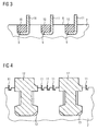
- FIG. 3 is a section of a rotor 2 to see.
- the rotor 2 has in this case in grooves 9 with Stemmmaterial 10 caulked sealing strips 11.
- the ultrasonic probe 1 not shown in detail.
- the ultrasonic probe 1 would be placed on the surface 6 to be tested. Between the Ultraschallprüfkopf requirements 3 and the surface to be tested 6, a coupling agent is arranged. An ultrasound coupling between the Ultraschallprüfkopf requirements 3 and the surface to be tested 6 is ensured.
- FIG. 4 is another section of a rotor 2 shown.
- the rotor 2 comprises, in addition to the sealing bands 11, turbine blades 12 arranged in blade grooves 13.
- the test head holder 5 has a first material 14, which is arranged around the ultrasonic test head 1.
- the projecting beyond the edge 4 Part 15 of the test head holder 5 is made of a flexible material.
- This flexible material is a rubber.
- the test head holder 5 comprises brushes, which are not shown in detail, which protrude beyond the edge.
- the projecting beyond the edge part of the educakopfhalterung 5 is formed as a rubber lip 16, which rubber lip 16 has a slot 17 which is formed such that a sealing tape 11 is fitted. Through this slot 17 and the sealing tape 11 no coupling agent should flow out.
- a supply means 18 is provided for supplying coupling agent.
- the amount of supplied coupling agent should be such that there is always enough coupling agent between the Ultraschallprüfkopf requirements 3 and the surface to be tested 6.
- the supply means 18 is formed as a tube.
Landscapes
- Physics & Mathematics (AREA)
- Health & Medical Sciences (AREA)
- Life Sciences & Earth Sciences (AREA)
- Chemical & Material Sciences (AREA)
- Analytical Chemistry (AREA)
- Biochemistry (AREA)
- General Health & Medical Sciences (AREA)
- General Physics & Mathematics (AREA)
- Immunology (AREA)
- Pathology (AREA)
- Investigating Or Analyzing Materials By The Use Of Ultrasonic Waves (AREA)
- Ultra Sonic Daignosis Equipment (AREA)
Description
- Die Erfindung betrifft einen Ultraschallprüfkopf umfassend eine Ultraschallprüfkopffläche, die durch einen Rand begrenzt ist. Solche Ultraschallpröfköpfe sind aus
US 4 033 178 undUS 5 567 881 bekannt. - Die Ultraschallprüftechnik wird in vielen Gebieten des Maschinenbaus eingesetzt, um beispielsweise Ungänzen in Rotoren von Dampfturbinen, Gasturbinen oder Generatoren aufzufinden. Die Ultraschalltechnik hat sich hierbei als zuverlässige Prüftechnik bewährt. Bei der Ultraschallprüftechnik kommen konventionelle Prüfköpfe als auch die sogenannten Phased Array Prüfköpfe zum Einsatz. Für ein gutes Prüfergebnis ist es wichtig, dass der Ultraschallprüfkopf mit der Oberfläche des Prüfgegenstandes ultraschalltechnisch verbunden ist. Dadurch wird ein Eindringen der Ultraschallwelle in den Prüfgegenatand gewährleistet. Ein Ultraschallprüfkopf umfasst eine Ultraschallprüfkopffläche, von der aus die Ultraschallwellen ausgestrahlt werden. Damit die Ultraschallwellen gut in den Prüfgegenstand eindringen können, wird üblicherweise ein Koppelmittel zwischen der Ultraschallprüfkopffläche und dem Früfgegenstand angeordnet. Dieses Koppelmittel kann beispielsweise Wasser oder ein Gel sein.
- Viele Prüfgegenstände weisen eine Oberfläche auf, die nicht eben ist und Konturen aufweist. Eine optimale Ankopplung des Ultraschallprüfkopfes auf diese Oberfläche ist daher erschwert. Beispielsweise sind sogenannte Dichtbänder bei Turbinen derart angeordnet, dass sogenannte Dichtlippen aus einer Oberfläche herausragen. Ein Ultraschallprüfkopf sollte möglichst nahe an diese Oberfläche angekoppelt werden. Die Dichtlippen verhindern allerdings eine direkte Ankopplung an die zu prüfende Oberfläche. Die Dichtbänder werden in Nuten eingestemmt. Wenn ein mit Dichtbändern versehener Rotor ultraschalltechnisch geprüft werden soll, werden derzeit die Dichtbänder aus den Nuten gezogen. Allerdings besteht selbst bei gezogenen Dichtbändern das Problem, dass sich nicht genügend Koppelmittel zwischen dem Rotor und dem Ultraschallprüfkopf befindet. Es kann sein, dass das Koppelmittel in den freien Nuten verschwindet und eine gute Ankopplung des Prüfkopfes an die Prüffläche nicht möglich ist.
- Es ist üblich, die Ankopplung des Ultraschallprüfkopfes durch benetzen bzw. beträufeln oder einkleistern des Rotors mit Öl zu gewährleisten. Allerdings ist der dafür benötigte Zeitaufwand erheblich. Der Rotor wird bei dieser Methode mit einem Öl benetzt, was mit einem Pinsel erfolgt. Der Rotor dreht sich hierbei mit wenigen Umdrehungen pro Minute. Allerdings sind die Nuten bei solch einer Methode stellenweise sehr unzureichend mit dem Koppelmittel gefüllt. Die Prüfergebnisse sind daher nicht optimal.
- Wünschenswert wäre es eine Prüfmöglichkeit mit Ultraschallprüfköpfen zu haben, bei der die Ankopplung an die zu prüfende Fläche verbessert ist.
- An dieser Stelle setzt die Erfindung an, deren Aufgabe es ist, die Ankopplung eines Ultraschallprüfkopfes auf eine zu prüfende Fläche zu verbessern.
- Die Aufgabe wird gelöst durch einen Ultraschallprüfkopf umfassend eine Ultraschallprüfkopffläche, die durch einen Rand begrenzt ist, wobei eine Prüfkopfhalterung um den Ultraschallprüfkopf entlang des Randes angeordnet ist, wobei die Prüfkopfhalterung über die Ultraschallprüfkopffläche ragt.
- Die Erfindung geht u.a. von dem Gedanken aus, dass der Ultraschallprüfkopf durch einen Rand begrenzt wird und dass ein Koppelmittel zwischen der Ultraschallprüfkopffläche und der zu prüfenden Oberfläche die Möglichkeit hat seitlich am Ultraschallprüfkopf zu entweichen. Die Erfindung schlägt daher vor, um den Rand des Ultraschallprüfkopfes eine Prüfkopfhalterung anzuordnen, die ein Entweichen des Koppelmittels verhindert. Die Prüfkopfhalterung sollte daher derart über den Rand hinausragen, dass ein Kontakt zwischen der Oberfläche und der Prüfkopfhalterung entsteht. Eine Bewegung des Ultraschallprüfkopfes entlang der zu prüfenden Oberfläche ist nunmehr problemlos möglich, da das Koppelmittel zwischen der Ultraschallprüfkopffläche und der zu prüfenden Oberfläche durch die Prüfkopfhalterung mit gezogen wird.
- Die Prüfkopfhalterung wirkt sozusagen als Scheibenwischer.
- Die Früfkopfhalterung ist derart ausgebildet, dass diese einen flexiblen Rahmen bildet, der als Rückhaltevorrichtung für das Koppelmittel dient. Eine Beschädigung des Prüfkopfes oder von Vorsatzteilen durch Grate wird dadurch wirksam vermieden, da eine gleichmäßigere Ankopplung gewährleistet ist und die Ultraschallsignale bei der Ultraschallprüfung verbessert sind. Neben der erheblichen Zeitersparnis während einer Ultraschallprüfung ist eine verbesserte Prüfempfindlichkeit möglich.
- Vorteilhafte Weiterbildungen sind in den Unteransprüchen angegeben.
- Vorteilhafterweise weist die Prüfkopfhalterung einen Kontaktrand auf, der derart über den Rand ragt, dass der Kontaktrand in einer Ebene liegt. Das das Koppelmittel meistens eine viskose Flüssigkeit ist, ist es natürlich von Vorteil, wenn ein Ausströmen des Koppelmittels in allen Richtungen verhindert wird. Daher ist es von Vorteil, wenn die Prüfkopfhalterung eine Lücke offen lässt, um ein Ausströmen des Koppelmittels zu Verhindern. Der Kontaktrand sollte daher in einer Ebene liegen.
- Erfindungsgemäß besteht der über den Rand hinausragende Teil der Prüfkopfhalterung aus einem flexiblen Material. Ähnlich wie bei einem Scheibenwischer kann die Prüfkopfhalterung derart ausgebildet werden, dass das Koppelmittel durch den über den Rand hinausragenden Teil der Prüfkopfhalterung mitgezogen wird. Ein möglicher Spalt zwischen der Prüfkopfhalterung und der zu prüfenden Oberfläche wird dadurch minimiert, wodurch ein Ausströmen des Koppelmittels weiterhin wirksam vermieden wird.
- Erfindungsgemäß ist das flexible Material ein Gummi. Das Material Gummi hat sich als geeignetes Material erwiesen, da die Rückstellkräfte in Bezug auf die viskosen Eigenschaften des Koppelmittels ideal sind.
- Erfindungsgemäß wird der über den Rand hinausragende Teil der Prüfkopfhalterung als eine Gummilippe ausgebildet. Ähnlich wie bei einem Scheibenwischer sollte die Prüfkopfhalterung derart ausgebildet sein, dass die Rückstellkräfte bei einer Bewegung des Ultraschallprüfkopfes optimiert sind, d.h. dass ein Ausströmen des Koppelmittels verhindert wird.
- In einer vorteilhaften Weiterbildung umfasst der über den Rand hinausragende Teil der Prüfköpfe Bürsten. Mit Bürsten wird ein ähnlicher Effekt erreicht wie mit Gummilippen. Auch Bürsten haben die Eigenschaft ein Koppelmittel zurückzuhalten, wobei Bürsten gegen eine zu prüfende Oberfläche gedrückt werden können.
- In einer weiteren vorteilhaften Weiterbildung weist die Prüfkopfhalterung ein Zuführ-Mittel zum Zuführen von Koppelmittel auf. Es ist nahezu nicht möglich, einen komplett dichten Raum zwischen der zu prüfenden Oberfläche und der Ultraschallprüfkopffläche auszubilden. Ein geringer Teil des Koppelmittels wird naturgemäß in einem Spalt zwischen der Prüfkopfhalterung und der zu prüfenden Oberfläche ausströmen. Durch ein permanentes Zuführen von Koppelmittel in den Raum zwischen der Ultraschallprüfkopffläche und der zu prüfenden Oberfläche wird sichergestellt, dass in diesem Raum genügend Koppelmittel vorhanden ist. Vorteilhafterweise ist das Zuführ-Mittel als ein Rohr zum Führen von Koppelmittel ausgebildet.
- Ein Ausführungsbeispiel der Erfindung wird anhand der folgenden Figuren näher erläutert. Komponenten mit ähnlicher Funktionsweise weisen dieselben Bezugszeichen auf.
- Es zeigen:
- FIG 1
- eine perspektivische Darstellung eines Ultraschallprüfkopfes;
- FIG 2
- eine Seitenansicht des Ultraschallprüfkopfes;
- FIG 3
- eine Seitenansicht von Dichtbändern;
- FIG 4
- eine Seitenansicht eines Ausschnitts eines Rotors mit Turbinenschaufeln und Dichtbändern.
- Die
FIG 1 zeigt einen Ultraschallprüfkopf 1, der zur Durchführung einer Ultraschallprüfung an einen Ausschnitt eines Rotors 2 angekoppelt ist. Der Ultraschallprüfkopf 1 weist eine in derFIG 1 nicht näher dargestellte Ultraschallprüfkopffläche 3 auf, die durch einen Rand 4 begrenzt ist. Um diesen Rand 4 ist eine Prüfkopfhalterung 5 angeordnet. Die Prüfkopfhalterung 5 ist um den gesamten Ultraschallprüfkopf 1 angeordnet und ragt über die Ultraschallprüfkopffläche 3 hinaus. Die Prüfkopfhalterung 5 ist hierbei um den Ultraschallprüfkopf 1 entlang des Randes 4 angeordnet. Der Ultraschallprüfkopf 1 wird auf eine zu prüfende Oberfläche 6 angeordnet. Ein möglicher Spalt zwischen der Prüfkopfhalterung 5 und der zu prüfenden Oberfläche 6 sollte minimiert werden. Die Prüfkopfhalterung 5 weist einen Kontaktrand 7 auf, wobei der Kontaktrand 7 in einer Ebene 8 liegt. In derFIG 2 ist eine Seitenansicht des Ultraschallprüfkopfes 1 zu sehen. Der Ultraschallprüfkopf 1 wird auf die zu prüfende Oberfläche 6 derart angeordnet, dass möglichst kein Spalt zwischen dem Kontaktrand 7 und der zu prüfenden Oberfläche 6 entsteht. Die zu prüfende Oberfläche 6 kann die Oberfläche eines Turbinenrotors oder die Oberfläche eines Generatorrotors sein. In derFIG 3 ist ein Ausschnitt eines Rotors 2 zu sehen. Der Rotor 2 weist hierbei in Nuten 9 mit Stemmmaterial 10 eingestemmte Dichtbänder 11 auf. Der Übersichtlichkeit wegen ist in derFIG 3 der Ultraschallprüfkopf 1 nicht näher dargestellt. In der Praxis würde der Ultraschallprüfkopf 1 auf die zu prüfende Oberfläche 6 angeordnet werden. Zwischen der Ultraschallprüfkopffläche 3 und der zu prüfenden Oberfläche 6 wird ein Koppelmittel angeordnet. Eine ultraschalltechnische Kopplung zwischen der Ultraschallprüfkopffläche 3 und der zu prüfenden Oberfläche 6 wird dadurch gewährleistet. - In der
FIG 4 ist ein weiterer Ausschnitt eines Rotors 2 dargestellt. Der Rotor 2 umfasst neben den Dichtbändern 11 in Schaufelnuten 13 angeordnete Turbinenschaufeln 12 auf. - Eine Prüfung des Rotors 2 ist zwischen den Turbinenschaufeln 12 möglich.
- Die Prüfkopfhalterung 5 weist ein erstes Material 14 auf, das um den Ultraschallprüfkopf 1 angeordnet ist. Der über den Rand 4 hinausragende Teil 15 der Prüfkopfhalterung 5 besteht aus einem flexiblen Material. Dieses flexible Material ist ein Gummi. In einer alternativen Ausführungsform umfasst die Prüfkopfhalterung 5 Bürsten, die nicht näher dargestellt sind, die über den Rand hinausragen.
- Der über den Rand hinausragende Teil der Prüfkopfhalterung 5 wird als eine Gummilippe 16 ausgebildet, welche Gummilippe 16 einen Schlitz 17 aufweist, der derart ausgebildet ist, dass ein Dichtband 11 eingepasst ist. Durch diesen Schlitz 17 und dem Dichtband 11 sollte kein Koppelmittel ausströmen. Um eine ausreichende Menge an Koppelmittel zwischen der Ultraschallprüfkopffläche 3 und der zu prüfenden Oberfläche 6 zu haben, ist ein Zuführ-Mittel 18 zum Zuführen von Koppelmittel vorgesehen. Die Menge an zugeführtem Koppelmittel sollte derart sein, dass immer derart genügend Koppelmittel zwischen der Ultraschallprüfkopffläche 3 und der zu prüfenden Oberfläche 6 ist. Idealerweise ist das Zuführ-Mittel 18 als Rohr ausgebildet.
Claims (6)
- Ultraschallprüfkopf (1),
umfassend eine Ultraschallprüfkopffläche (3), die durch einen Rand (4) begrenzt ist,
dadurch gekennzeichnet, dass
eine Prüfkopfhalterung (5) um den Ultraschallprüfkopf (1) entlang des Randes (4) angeordnet ist,
wobei die Prüfkopfhalterung (5) über die Ultraschallprüfkopffläche (3) ragt,
wobei der über den Rand (4) hinausragende Teil der Prüfkopfhalterung (5) aus einem flexiblen Material besteht,
wobei das flexible Material ein Gummi ist,
wobei der über den Rand (4) hinausragende Teil der Prüfkopfhalterung (5) als eine Gummilippe (16) ausgebildet ist, wobei die Gummilippe (16) einen Schlitz (17) zum Aufnehmen eines Dichtbandes (11) aufweist. - Ultraschallprüfkopf (1) nach Anspruch 1,
wobei die Prüfkopfhalterung (5) einen Kontaktrand (7) aufweist, der derart über den Rand (4) ragt, dass der Kontaktrand (7) in einer Ebene (8) liegt. - Ultraschallprüfkopf (1) nach Anspruch 1 oder 2,
wobei der über den Rand (4) hinausragende Teil der Prüf-kopfhalterung (5) Bürsten fasst. - Ultraschallprüfkopf (1) nach Anspruch 3,
wobei die Bürsten zum Zurückhalten von Koppelmittel ausgebildet sind. - Ultraschallprüfkopf (1) nach einem der vorhergehenden Ansprüche,
wobei die Prüfkopfhalterung (5) ein Zuführ-Mittel 18 zum Zuführen von Koppelmittel aufweist. - Ultraschallprüfkopf (1) nach Anspruch 5,
wobei das Zuführ-Mittel (18) als ein Rohr zum Führen von Koppelmittel ausgebildet ist.
Priority Applications (1)
| Application Number | Priority Date | Filing Date | Title |
|---|---|---|---|
| EP09781889A EP2316019B1 (de) | 2008-08-25 | 2009-08-17 | Ultraschallprüfkopf |
Applications Claiming Priority (3)
| Application Number | Priority Date | Filing Date | Title |
|---|---|---|---|
| EP08015001A EP2159576A1 (de) | 2008-08-25 | 2008-08-25 | Ultraschallprüfkopf |
| EP09781889A EP2316019B1 (de) | 2008-08-25 | 2009-08-17 | Ultraschallprüfkopf |
| PCT/EP2009/060595 WO2010026036A1 (de) | 2008-08-25 | 2009-08-17 | Ultraschallprüfkopf |
Publications (2)
| Publication Number | Publication Date |
|---|---|
| EP2316019A1 EP2316019A1 (de) | 2011-05-04 |
| EP2316019B1 true EP2316019B1 (de) | 2012-01-04 |
Family
ID=41429282
Family Applications (2)
| Application Number | Title | Priority Date | Filing Date |
|---|---|---|---|
| EP08015001A Withdrawn EP2159576A1 (de) | 2008-08-25 | 2008-08-25 | Ultraschallprüfkopf |
| EP09781889A Not-in-force EP2316019B1 (de) | 2008-08-25 | 2009-08-17 | Ultraschallprüfkopf |
Family Applications Before (1)
| Application Number | Title | Priority Date | Filing Date |
|---|---|---|---|
| EP08015001A Withdrawn EP2159576A1 (de) | 2008-08-25 | 2008-08-25 | Ultraschallprüfkopf |
Country Status (4)
| Country | Link |
|---|---|
| EP (2) | EP2159576A1 (de) |
| CN (1) | CN102150039B (de) |
| AT (1) | ATE540311T1 (de) |
| WO (1) | WO2010026036A1 (de) |
Families Citing this family (7)
| Publication number | Priority date | Publication date | Assignee | Title |
|---|---|---|---|---|
| FR3033050B1 (fr) * | 2015-02-25 | 2019-06-28 | Sncf Mobilites | Support de capteur a ultrasons et systeme de detection comportant un tel support |
| DE102018208293A1 (de) | 2018-05-25 | 2019-11-28 | Siemens Aktiengesellschaft | Prüfvorrichtung |
| CN109709216B (zh) * | 2019-01-17 | 2022-01-04 | 济宁康华机电科技有限公司 | 一种用于金属探伤的便于操作的检测设备 |
| US11313839B2 (en) * | 2019-12-16 | 2022-04-26 | The Boeing Company | Apparatus, system, and method for ultrasonic inspection of a variable radius joint |
| US11940419B2 (en) | 2020-07-09 | 2024-03-26 | The Boeing Company | Apparatus, system, and method for ultrasonic inspection of a variable angle joint |
| EP4011300A1 (de) * | 2020-12-14 | 2022-06-15 | Iconeus | Ultraschallsondenhaltevorrichtungen für kleinkinder |
| CN114324590B (zh) * | 2021-12-29 | 2024-03-08 | 北京信泰智合科技发展有限公司 | 一种超声波探头耦合液保持装置、钢轨监测系统及方法 |
Family Cites Families (5)
| Publication number | Priority date | Publication date | Assignee | Title |
|---|---|---|---|---|
| DE971832C (de) * | 1953-01-23 | 1959-04-02 | Herbert Krautkraemer | Verfahren zur Ankopplung eines Schallgebers oder Schallempfaengers an einen Pruefling |
| US4033178A (en) * | 1976-04-23 | 1977-07-05 | The Babcock & Wilcox Company | Fluid coupled test probe |
| GB2139353B (en) * | 1983-05-06 | 1986-06-25 | Froude Consine Ltd | Test-piece testing apparatus |
| US5567881A (en) * | 1995-05-05 | 1996-10-22 | Mcdonnell Douglas Corporation | Method and apparatus for inspecting a structural part having surface irregularities |
| US7320249B2 (en) * | 2004-09-16 | 2008-01-22 | The Boeing Company | Magnetically attracted inspecting apparatus and method using a fluid bearing |
-
2008
- 2008-08-25 EP EP08015001A patent/EP2159576A1/de not_active Withdrawn
-
2009
- 2009-08-17 CN CN200980133305.7A patent/CN102150039B/zh not_active Expired - Fee Related
- 2009-08-17 WO PCT/EP2009/060595 patent/WO2010026036A1/de not_active Ceased
- 2009-08-17 EP EP09781889A patent/EP2316019B1/de not_active Not-in-force
- 2009-08-17 AT AT09781889T patent/ATE540311T1/de active
Also Published As
| Publication number | Publication date |
|---|---|
| EP2316019A1 (de) | 2011-05-04 |
| EP2159576A1 (de) | 2010-03-03 |
| WO2010026036A1 (de) | 2010-03-11 |
| ATE540311T1 (de) | 2012-01-15 |
| CN102150039A (zh) | 2011-08-10 |
| CN102150039B (zh) | 2013-06-12 |
Similar Documents
| Publication | Publication Date | Title |
|---|---|---|
| EP2159576A1 (de) | Ultraschallprüfkopf | |
| EP2513486B1 (de) | Dichtung einer gebläseanordnung | |
| DE69429692T2 (de) | Ultraschallprüfverfahren für Rohre und Rohrstränge und dazugehörende Fühlereinrichtung | |
| DE2813129C2 (de) | Ventil | |
| DE3138471C3 (de) | Implantierbare Leitung | |
| DE19718490A1 (de) | Wischblatt für Scheiben von Kraftfahrzeugen | |
| DE112008003542T5 (de) | Gaszufuhrstruktur | |
| DE112014003487T5 (de) | Elektrophoresemediumbehälter und Elektrophoresevorrichtung | |
| DE3202822A1 (de) | Ultraschallsonde fuer akupunkturbehandlung | |
| EP4374099A1 (de) | Segment für einen sensorträgerkörper eines molches zur inspektion einer rohrleitung | |
| DE102018007917A1 (de) | Anbauteil für einen Wischerarm | |
| EP1764154B1 (de) | Vorrichtung zum Zerkleinern von biologischem Probematerial | |
| DE3221145A1 (de) | Selbstklebender piezoelektrischer wandler und vorrichtung zur anwendung des wandlers | |
| DE19801117C1 (de) | Verfahren und Vorrichtung zur Prüfung der Qualität eines eine Membran umfassenden flächigen Elements | |
| DE10334609B4 (de) | Gelenkfreies Wischblatt | |
| DE102016213345A1 (de) | Waschdüse für Fahrzeug | |
| EP1894512B1 (de) | Stülpschlauch mit 2-Komponentenschmiermittel | |
| EP3850684B1 (de) | Dichtungsanordnung zur abdichtung eines rahmenteils | |
| DE3026540A1 (de) | Verfahren und vorrichtung zum magnetographischen pruefen von bereichen magnetisierbarer pruefteile | |
| DE102009053565A1 (de) | Schneidmesser eines Tabakschneiders | |
| EP4450940A1 (de) | Prüfadapter für einen hochvoltkabelstrang, prüfsystem für einen hochvoltkabelstrang, sowie verfahren zur herstellung eines prüfadapters für einen hochvoltkabelstrang | |
| EP1734365B1 (de) | Körperflüssigkeit-Analysevorrichtung mit einem Testfelder aufweisenden Testband | |
| DE102010044096A1 (de) | Prüfeinrichtung für eine Antriebseinrichtung einer Scheibenwischvorrichtung | |
| DE10161231B4 (de) | Verfahren zur Überwachung oder Kontrolle der Oberflächenbearbeitung eines Werkstückes und dessen Verwendung | |
| DE10039974A1 (de) | Kraftstoffpumpe |
Legal Events
| Date | Code | Title | Description |
|---|---|---|---|
| PUAI | Public reference made under article 153(3) epc to a published international application that has entered the european phase |
Free format text: ORIGINAL CODE: 0009012 |
|
| 17P | Request for examination filed |
Effective date: 20110209 |
|
| AK | Designated contracting states |
Kind code of ref document: A1 Designated state(s): AT BE BG CH CY CZ DE DK EE ES FI FR GB GR HR HU IE IS IT LI LT LU LV MC MK MT NL NO PL PT RO SE SI SK SM TR |
|
| AX | Request for extension of the european patent |
Extension state: AL BA RS |
|
| GRAP | Despatch of communication of intention to grant a patent |
Free format text: ORIGINAL CODE: EPIDOSNIGR1 |
|
| GRAS | Grant fee paid |
Free format text: ORIGINAL CODE: EPIDOSNIGR3 |
|
| DAX | Request for extension of the european patent (deleted) | ||
| GRAA | (expected) grant |
Free format text: ORIGINAL CODE: 0009210 |
|
| AK | Designated contracting states |
Kind code of ref document: B1 Designated state(s): AT BE BG CH CY CZ DE DK EE ES FI FR GB GR HR HU IE IS IT LI LT LU LV MC MK MT NL NO PL PT RO SE SI SK SM TR |
|
| REG | Reference to a national code |
Ref country code: GB Ref legal event code: FG4D Free format text: NOT ENGLISH |
|
| REG | Reference to a national code |
Ref country code: CH Ref legal event code: EP |
|
| REG | Reference to a national code |
Ref country code: AT Ref legal event code: REF Ref document number: 540311 Country of ref document: AT Kind code of ref document: T Effective date: 20120115 |
|
| REG | Reference to a national code |
Ref country code: IE Ref legal event code: FG4D |
|
| REG | Reference to a national code |
Ref country code: CH Ref legal event code: NV Representative=s name: SIEMENS SCHWEIZ AG |
|
| REG | Reference to a national code |
Ref country code: DE Ref legal event code: R096 Ref document number: 502009002435 Country of ref document: DE Effective date: 20120308 |
|
| REG | Reference to a national code |
Ref country code: NL Ref legal event code: VDEP Effective date: 20120104 |
|
| PG25 | Lapsed in a contracting state [announced via postgrant information from national office to epo] |
Ref country code: SI Free format text: LAPSE BECAUSE OF FAILURE TO SUBMIT A TRANSLATION OF THE DESCRIPTION OR TO PAY THE FEE WITHIN THE PRESCRIBED TIME-LIMIT Effective date: 20120104 |
|
| LTIE | Lt: invalidation of european patent or patent extension |
Effective date: 20120104 |
|
| PG25 | Lapsed in a contracting state [announced via postgrant information from national office to epo] |
Ref country code: LT Free format text: LAPSE BECAUSE OF FAILURE TO SUBMIT A TRANSLATION OF THE DESCRIPTION OR TO PAY THE FEE WITHIN THE PRESCRIBED TIME-LIMIT Effective date: 20120104 Ref country code: NO Free format text: LAPSE BECAUSE OF FAILURE TO SUBMIT A TRANSLATION OF THE DESCRIPTION OR TO PAY THE FEE WITHIN THE PRESCRIBED TIME-LIMIT Effective date: 20120404 Ref country code: IS Free format text: LAPSE BECAUSE OF FAILURE TO SUBMIT A TRANSLATION OF THE DESCRIPTION OR TO PAY THE FEE WITHIN THE PRESCRIBED TIME-LIMIT Effective date: 20120504 Ref country code: HR Free format text: LAPSE BECAUSE OF FAILURE TO SUBMIT A TRANSLATION OF THE DESCRIPTION OR TO PAY THE FEE WITHIN THE PRESCRIBED TIME-LIMIT Effective date: 20120104 Ref country code: BG Free format text: LAPSE BECAUSE OF FAILURE TO SUBMIT A TRANSLATION OF THE DESCRIPTION OR TO PAY THE FEE WITHIN THE PRESCRIBED TIME-LIMIT Effective date: 20120404 Ref country code: NL Free format text: LAPSE BECAUSE OF FAILURE TO SUBMIT A TRANSLATION OF THE DESCRIPTION OR TO PAY THE FEE WITHIN THE PRESCRIBED TIME-LIMIT Effective date: 20120104 |
|
| REG | Reference to a national code |
Ref country code: IE Ref legal event code: FD4D |
|
| PG25 | Lapsed in a contracting state [announced via postgrant information from national office to epo] |
Ref country code: FI Free format text: LAPSE BECAUSE OF FAILURE TO SUBMIT A TRANSLATION OF THE DESCRIPTION OR TO PAY THE FEE WITHIN THE PRESCRIBED TIME-LIMIT Effective date: 20120104 Ref country code: PL Free format text: LAPSE BECAUSE OF FAILURE TO SUBMIT A TRANSLATION OF THE DESCRIPTION OR TO PAY THE FEE WITHIN THE PRESCRIBED TIME-LIMIT Effective date: 20120104 Ref country code: GR Free format text: LAPSE BECAUSE OF FAILURE TO SUBMIT A TRANSLATION OF THE DESCRIPTION OR TO PAY THE FEE WITHIN THE PRESCRIBED TIME-LIMIT Effective date: 20120405 Ref country code: LV Free format text: LAPSE BECAUSE OF FAILURE TO SUBMIT A TRANSLATION OF THE DESCRIPTION OR TO PAY THE FEE WITHIN THE PRESCRIBED TIME-LIMIT Effective date: 20120104 Ref country code: PT Free format text: LAPSE BECAUSE OF FAILURE TO SUBMIT A TRANSLATION OF THE DESCRIPTION OR TO PAY THE FEE WITHIN THE PRESCRIBED TIME-LIMIT Effective date: 20120504 |
|
| PG25 | Lapsed in a contracting state [announced via postgrant information from national office to epo] |
Ref country code: CY Free format text: LAPSE BECAUSE OF FAILURE TO SUBMIT A TRANSLATION OF THE DESCRIPTION OR TO PAY THE FEE WITHIN THE PRESCRIBED TIME-LIMIT Effective date: 20120104 |
|
| PG25 | Lapsed in a contracting state [announced via postgrant information from national office to epo] |
Ref country code: EE Free format text: LAPSE BECAUSE OF FAILURE TO SUBMIT A TRANSLATION OF THE DESCRIPTION OR TO PAY THE FEE WITHIN THE PRESCRIBED TIME-LIMIT Effective date: 20120104 Ref country code: CZ Free format text: LAPSE BECAUSE OF FAILURE TO SUBMIT A TRANSLATION OF THE DESCRIPTION OR TO PAY THE FEE WITHIN THE PRESCRIBED TIME-LIMIT Effective date: 20120104 Ref country code: SE Free format text: LAPSE BECAUSE OF FAILURE TO SUBMIT A TRANSLATION OF THE DESCRIPTION OR TO PAY THE FEE WITHIN THE PRESCRIBED TIME-LIMIT Effective date: 20120104 Ref country code: DK Free format text: LAPSE BECAUSE OF FAILURE TO SUBMIT A TRANSLATION OF THE DESCRIPTION OR TO PAY THE FEE WITHIN THE PRESCRIBED TIME-LIMIT Effective date: 20120104 Ref country code: IE Free format text: LAPSE BECAUSE OF FAILURE TO SUBMIT A TRANSLATION OF THE DESCRIPTION OR TO PAY THE FEE WITHIN THE PRESCRIBED TIME-LIMIT Effective date: 20120104 Ref country code: RO Free format text: LAPSE BECAUSE OF FAILURE TO SUBMIT A TRANSLATION OF THE DESCRIPTION OR TO PAY THE FEE WITHIN THE PRESCRIBED TIME-LIMIT Effective date: 20120104 |
|
| PLBE | No opposition filed within time limit |
Free format text: ORIGINAL CODE: 0009261 |
|
| STAA | Information on the status of an ep patent application or granted ep patent |
Free format text: STATUS: NO OPPOSITION FILED WITHIN TIME LIMIT |
|
| PG25 | Lapsed in a contracting state [announced via postgrant information from national office to epo] |
Ref country code: SK Free format text: LAPSE BECAUSE OF FAILURE TO SUBMIT A TRANSLATION OF THE DESCRIPTION OR TO PAY THE FEE WITHIN THE PRESCRIBED TIME-LIMIT Effective date: 20120104 |
|
| 26N | No opposition filed |
Effective date: 20121005 |
|
| REG | Reference to a national code |
Ref country code: DE Ref legal event code: R097 Ref document number: 502009002435 Country of ref document: DE Effective date: 20121005 |
|
| BERE | Be: lapsed |
Owner name: SIEMENS A.G. Effective date: 20120831 |
|
| PG25 | Lapsed in a contracting state [announced via postgrant information from national office to epo] |
Ref country code: MC Free format text: LAPSE BECAUSE OF NON-PAYMENT OF DUE FEES Effective date: 20120831 |
|
| PG25 | Lapsed in a contracting state [announced via postgrant information from national office to epo] |
Ref country code: ES Free format text: LAPSE BECAUSE OF FAILURE TO SUBMIT A TRANSLATION OF THE DESCRIPTION OR TO PAY THE FEE WITHIN THE PRESCRIBED TIME-LIMIT Effective date: 20120415 |
|
| PG25 | Lapsed in a contracting state [announced via postgrant information from national office to epo] |
Ref country code: BE Free format text: LAPSE BECAUSE OF NON-PAYMENT OF DUE FEES Effective date: 20120831 |
|
| PG25 | Lapsed in a contracting state [announced via postgrant information from national office to epo] |
Ref country code: MT Free format text: LAPSE BECAUSE OF FAILURE TO SUBMIT A TRANSLATION OF THE DESCRIPTION OR TO PAY THE FEE WITHIN THE PRESCRIBED TIME-LIMIT Effective date: 20120104 |
|
| PG25 | Lapsed in a contracting state [announced via postgrant information from national office to epo] |
Ref country code: TR Free format text: LAPSE BECAUSE OF FAILURE TO SUBMIT A TRANSLATION OF THE DESCRIPTION OR TO PAY THE FEE WITHIN THE PRESCRIBED TIME-LIMIT Effective date: 20120104 |
|
| PG25 | Lapsed in a contracting state [announced via postgrant information from national office to epo] |
Ref country code: SM Free format text: LAPSE BECAUSE OF FAILURE TO SUBMIT A TRANSLATION OF THE DESCRIPTION OR TO PAY THE FEE WITHIN THE PRESCRIBED TIME-LIMIT Effective date: 20120104 Ref country code: LU Free format text: LAPSE BECAUSE OF NON-PAYMENT OF DUE FEES Effective date: 20120817 |
|
| PG25 | Lapsed in a contracting state [announced via postgrant information from national office to epo] |
Ref country code: HU Free format text: LAPSE BECAUSE OF FAILURE TO SUBMIT A TRANSLATION OF THE DESCRIPTION OR TO PAY THE FEE WITHIN THE PRESCRIBED TIME-LIMIT Effective date: 20090817 |
|
| PG25 | Lapsed in a contracting state [announced via postgrant information from national office to epo] |
Ref country code: MK Free format text: LAPSE BECAUSE OF FAILURE TO SUBMIT A TRANSLATION OF THE DESCRIPTION OR TO PAY THE FEE WITHIN THE PRESCRIBED TIME-LIMIT Effective date: 20120104 |
|
| REG | Reference to a national code |
Ref country code: AT Ref legal event code: MM01 Ref document number: 540311 Country of ref document: AT Kind code of ref document: T Effective date: 20140817 |
|
| PG25 | Lapsed in a contracting state [announced via postgrant information from national office to epo] |
Ref country code: AT Free format text: LAPSE BECAUSE OF NON-PAYMENT OF DUE FEES Effective date: 20140817 |
|
| REG | Reference to a national code |
Ref country code: FR Ref legal event code: PLFP Year of fee payment: 8 |
|
| REG | Reference to a national code |
Ref country code: FR Ref legal event code: PLFP Year of fee payment: 9 |
|
| REG | Reference to a national code |
Ref country code: CH Ref legal event code: PCOW Free format text: NEW ADDRESS: WERNER-VON-SIEMENS-STRASSE 1, 80333 MUENCHEN (DE) |
|
| PGFP | Annual fee paid to national office [announced via postgrant information from national office to epo] |
Ref country code: IT Payment date: 20170829 Year of fee payment: 9 Ref country code: FR Payment date: 20170814 Year of fee payment: 9 Ref country code: GB Payment date: 20170811 Year of fee payment: 9 |
|
| PGFP | Annual fee paid to national office [announced via postgrant information from national office to epo] |
Ref country code: DE Payment date: 20171019 Year of fee payment: 9 |
|
| PGFP | Annual fee paid to national office [announced via postgrant information from national office to epo] |
Ref country code: CH Payment date: 20171110 Year of fee payment: 9 |
|
| REG | Reference to a national code |
Ref country code: DE Ref legal event code: R119 Ref document number: 502009002435 Country of ref document: DE |
|
| REG | Reference to a national code |
Ref country code: CH Ref legal event code: PL |
|
| GBPC | Gb: european patent ceased through non-payment of renewal fee |
Effective date: 20180817 |
|
| PG25 | Lapsed in a contracting state [announced via postgrant information from national office to epo] |
Ref country code: CH Free format text: LAPSE BECAUSE OF NON-PAYMENT OF DUE FEES Effective date: 20180831 Ref country code: LI Free format text: LAPSE BECAUSE OF NON-PAYMENT OF DUE FEES Effective date: 20180831 |
|
| PG25 | Lapsed in a contracting state [announced via postgrant information from national office to epo] |
Ref country code: IT Free format text: LAPSE BECAUSE OF NON-PAYMENT OF DUE FEES Effective date: 20180817 Ref country code: DE Free format text: LAPSE BECAUSE OF NON-PAYMENT OF DUE FEES Effective date: 20190301 |
|
| PG25 | Lapsed in a contracting state [announced via postgrant information from national office to epo] |
Ref country code: FR Free format text: LAPSE BECAUSE OF NON-PAYMENT OF DUE FEES Effective date: 20180831 |
|
| PG25 | Lapsed in a contracting state [announced via postgrant information from national office to epo] |
Ref country code: GB Free format text: LAPSE BECAUSE OF NON-PAYMENT OF DUE FEES Effective date: 20180817 |