EP2315714B1 - Vorrichtung zum vollautomatisierten kommissionieren von artikeln in auftragsladehilfsmittel - Google Patents
Vorrichtung zum vollautomatisierten kommissionieren von artikeln in auftragsladehilfsmittel Download PDFInfo
- Publication number
- EP2315714B1 EP2315714B1 EP09777437A EP09777437A EP2315714B1 EP 2315714 B1 EP2315714 B1 EP 2315714B1 EP 09777437 A EP09777437 A EP 09777437A EP 09777437 A EP09777437 A EP 09777437A EP 2315714 B1 EP2315714 B1 EP 2315714B1
- Authority
- EP
- European Patent Office
- Prior art keywords
- conveyor
- articles
- gripping
- storage
- order
- Prior art date
- Legal status (The legal status is an assumption and is not a legal conclusion. Google has not performed a legal analysis and makes no representation as to the accuracy of the status listed.)
- Not-in-force
Links
- 239000000872 buffer Substances 0.000 claims description 21
- 238000009825 accumulation Methods 0.000 claims description 16
- 230000005484 gravity Effects 0.000 claims description 8
- 238000012546 transfer Methods 0.000 claims description 8
- 230000001133 acceleration Effects 0.000 claims description 4
- 238000011144 upstream manufacturing Methods 0.000 claims description 3
- 230000003139 buffering effect Effects 0.000 claims 1
- 238000000034 method Methods 0.000 description 24
- 238000005516 engineering process Methods 0.000 description 10
- 230000008569 process Effects 0.000 description 6
- 230000004048 modification Effects 0.000 description 5
- 238000012986 modification Methods 0.000 description 5
- 238000012545 processing Methods 0.000 description 4
- 239000010410 layer Substances 0.000 description 3
- 238000007726 management method Methods 0.000 description 3
- 239000000463 material Substances 0.000 description 3
- 238000004806 packaging method and process Methods 0.000 description 3
- 210000002445 nipple Anatomy 0.000 description 2
- 235000013580 sausages Nutrition 0.000 description 2
- 230000009471 action Effects 0.000 description 1
- 238000013459 approach Methods 0.000 description 1
- 230000008901 benefit Effects 0.000 description 1
- 230000005540 biological transmission Effects 0.000 description 1
- 238000004364 calculation method Methods 0.000 description 1
- 239000000969 carrier Substances 0.000 description 1
- 230000000739 chaotic effect Effects 0.000 description 1
- 238000006243 chemical reaction Methods 0.000 description 1
- 230000001143 conditioned effect Effects 0.000 description 1
- 239000003814 drug Substances 0.000 description 1
- 229940079593 drug Drugs 0.000 description 1
- 239000000428 dust Substances 0.000 description 1
- 230000000977 initiatory effect Effects 0.000 description 1
- 238000002955 isolation Methods 0.000 description 1
- 238000005192 partition Methods 0.000 description 1
- 230000009467 reduction Effects 0.000 description 1
- 238000009420 retrofitting Methods 0.000 description 1
- 238000000926 separation method Methods 0.000 description 1
- 238000012163 sequencing technique Methods 0.000 description 1
- 239000002356 single layer Substances 0.000 description 1
Images


Classifications
-
- B—PERFORMING OPERATIONS; TRANSPORTING
- B65—CONVEYING; PACKING; STORING; HANDLING THIN OR FILAMENTARY MATERIAL
- B65G—TRANSPORT OR STORAGE DEVICES, e.g. CONVEYORS FOR LOADING OR TIPPING, SHOP CONVEYOR SYSTEMS OR PNEUMATIC TUBE CONVEYORS
- B65G1/00—Storing articles, individually or in orderly arrangement, in warehouses or magazines
- B65G1/02—Storage devices
- B65G1/04—Storage devices mechanical
- B65G1/137—Storage devices mechanical with arrangements or automatic control means for selecting which articles are to be removed
- B65G1/1373—Storage devices mechanical with arrangements or automatic control means for selecting which articles are to be removed for fulfilling orders in warehouses
- B65G1/1378—Storage devices mechanical with arrangements or automatic control means for selecting which articles are to be removed for fulfilling orders in warehouses the orders being assembled on fixed commissioning areas remote from the storage areas
-
- B—PERFORMING OPERATIONS; TRANSPORTING
- B65—CONVEYING; PACKING; STORING; HANDLING THIN OR FILAMENTARY MATERIAL
- B65G—TRANSPORT OR STORAGE DEVICES, e.g. CONVEYORS FOR LOADING OR TIPPING, SHOP CONVEYOR SYSTEMS OR PNEUMATIC TUBE CONVEYORS
- B65G1/00—Storing articles, individually or in orderly arrangement, in warehouses or magazines
- B65G1/02—Storage devices
- B65G1/04—Storage devices mechanical
- B65G1/137—Storage devices mechanical with arrangements or automatic control means for selecting which articles are to be removed
- B65G1/1373—Storage devices mechanical with arrangements or automatic control means for selecting which articles are to be removed for fulfilling orders in warehouses
- B65G1/1376—Storage devices mechanical with arrangements or automatic control means for selecting which articles are to be removed for fulfilling orders in warehouses the orders being assembled on a commissioning conveyor
-
- B—PERFORMING OPERATIONS; TRANSPORTING
- B65—CONVEYING; PACKING; STORING; HANDLING THIN OR FILAMENTARY MATERIAL
- B65G—TRANSPORT OR STORAGE DEVICES, e.g. CONVEYORS FOR LOADING OR TIPPING, SHOP CONVEYOR SYSTEMS OR PNEUMATIC TUBE CONVEYORS
- B65G47/00—Article or material-handling devices associated with conveyors; Methods employing such devices
- B65G47/74—Feeding, transfer, or discharging devices of particular kinds or types
- B65G47/90—Devices for picking-up and depositing articles or materials
- B65G47/904—Devices for picking-up and depositing articles or materials provided with rotary movements only
Definitions
- the present invention relates to a system for the fully automated, unmanned picking of articles, which are preferably stored in storage loading equipment, in order loading equipment, according to a picking order.
- a picking order comprises several items (lines) with different items in different numbers.
- Storage containers conveyed from a container storage to a picking station, where a picking person removes the items manually from the storage containers and they are in order container, which are arranged in the picking area.
- a material flow or warehouse management computer assigns a picking order to the order containers and ensures that the correct storage containers containing the articles required for the respective picking order are conveyed to the order picking station where the associated order container is processed.
- A-frames or picking machines are usually used.
- An exemplary A-frame is in the document US 5,755,552 disclosed.
- An A-frame is a picking machine in which, via shafts in which the articles are stacked on top of each other, these articles are delivered to a central conveyor belt, which is arranged centrally between the A-shaped legs of the machine frame.
- shaft pickers are used in particular for smaller, stably packed units, eg in the pharmaceutical sector. Due to the usually parallel operation, several shaft pickers with a common conveyor belt can achieve very high outputs (up to several 10,000 pieces per hour).
- the shafts are arranged in succession in the longitudinal direction of the tape and designed to accommodate different types of articles.
- a so-called ejector is provided, with the aid of which articles stored in the shaft are dropped onto the belt.
- the manholes are usually refilled manually, which can be a disadvantage with very high picking performances (eg 100 articles / min) because the manholes are not filled up fast enough.
- the picking machine is a fully automated and unmanned system, there is a need for further automation, especially in the field of articles that are not manageable with a picking machine.
- unloading robots and loading robots are known, in particular to load pallets with articles or to remove articles from the pallets.
- DE 10 2006 024 900 A1 An apparatus for handling pallets in and outside a so-called palletizing cell is described. Empty pallets are positioned at a loading site for loading. Then items such as boxes are conveyed via a roller conveyor to a palletizing robot to layer the items on the pallet.
- a suction lifting device of the palletizing robot is used, which is mounted above the roller conveyor on a frame-like frame in the horizontal and vertical directions movable. With such a total device can be implemented up to several 100 articles per hour.
- depalletizing robots which work in reverse, ie the pallets loaded with an article stack are depalletized in layers or individually.
- Packaging robots or palletizing robots are mentioned in the documents DE 40 27 497 A1 and US 5,175,692 B.
- the DE 198 20 537 A1 discloses a robot for sorting and packaging sausages to assemble the sausages to a next larger container, as already mentioned above.
- a sorting robot is generally used in the WO 03/091107 A1 disclosed.
- the articles to be picked should also contain articles that are not or only poorly manageable with a picking machine.
- the principle of "goods to man” should be used in order to implement articles stored in storage load equipment in order loading equipment.
- the picking is now fully automatic with a robotic gripping unit.
- the robot takes over the task of the order picker fully. He picks up the articles, which was originally one of the main reasons why people have ever been used in order picking, and handles used articles with a much higher speed and precision. People are in a system according to the invention - at least for picking - no longer needed.
- the robot can easily grab 1500 articles per hour from a conveyor belt and settle on a second conveyor belt, for example, which supplies the order containers arranged laterally to the second conveyor belt with the articles pre-ordered according to the picking orders and thus serves as a sorter.
- the robot With a picking capacity of even up to 4000 pieces per hour, you are exactly in the sector between the conventional ones manual order picking (1,000 pieces per hour) and classic automatic picking (10,000 pieces per hour and more).
- the robot also makes no mistakes when gripping.
- the articles are preferably implemented individually, which is easily possible due to the high speed, so that always the right number of articles of a type are implemented, which is not always the case with manual picking.
- the KommissionierTalkrate is also significantly lower because a robot never gets tired, so that there is no present in humans with increasing working time negatively affecting concentration drop.
- the system according to the invention it is possible to work for twenty-four hours every seven days.
- the system further comprises an image recognition unit for detecting and evaluating a location and an orientation of each article in the stream on the first conveyor, the image recognition unit being located upstream relative to the gripper and even disintegrating chaotically oriented articles within the stream; and in particular, can identify.
- the image recognition unit may be a camera system with which images of the article distribution on the first conveyor technology are recorded. It is irrelevant whether the items are conveyed directly on the conveyor or in loading equipment.
- the image processing software used according to the invention is capable of dissolving even articles in an upper layer of an article heap or stack in such a way that a respective location (position) and a respective orientation are known in order to be able to transmit position data corresponding to the gripping unit (relative to the conveyor technology) for gripping the articles.
- the image processing is simplified accordingly, if the articles are reasonably arranged, such as in a container or on a shelf with compartment division.
- the image recognition unit then only needs to determine the location of such articles that are actually present.
- each article is conveyed on its own article loading aid at a respectively predetermined position on the first conveyor line in the gripping area and gripped there together with the article loading aid and implemented.
- the gripping device can do without image recognition.
- these trays are at predetermined (raster) points relative to the first conveyor line, such as e.g. a webbing, before they come into the working or gripping area of the gripping unit.
- a superordinate control device such as e.g. a material flow computer or a warehouse management computer, then has knowledge of which article is arranged on which position of the conveyor belt. Due to the knowledge of the conveying speed, the position and orientation of the articles to be picked can thus be predicted and transmitted in advance in the form of position control data to the gripping unit.
- the geometrical dimensions of the articles can be stored in the system in order to transmit to the gripping unit already in advance the correct starting positions (from above, from left, from right, etc.) for initiating a gripping process.
- the gripping unit can implement articles with a respective total weight of up to 2 kg with accelerations of up to 150 m / s 2 .
- the working area preferably has a diameter of 1500 mm, with a stroke of preferably 60 mm.
- the gripper robot can cause accelerations of up to 10 g. These features allow for tremendous speed in the process of transfer, increasing order picking to as much as 4,000 items per hour.
- At least one second conveyor system is provided, which in the working area of the gripper unit connects obliquely, preferably vertically, to the first conveyor system and which is connected to the order loading aid buffer, in particular to the destination locations.
- the second conveyor then serves as a sorter and provides a variety of destinations or job loading equipment, such as order container, with articles to be picked.
- a plurality of gripper robots are arranged serially one behind the other relative to the first conveyor track.
- the first gripping robot can then grasp such articles from the stream of articles, which are arranged under chaotic in the article flow, without all other articles of the stream, which are not assigned to target points of this gripper unit associated second conveyor line, are also promoted from the first conveyor line, as it For example, in the conventional use of Linearschiebem, rotary valves, attacks, etc. was the case.
- a targeted access to arbitrary selectable articles in the Article flow on the first conveyor is possible at an outstanding speed.
- the second conveyor technique comprises a plurality of driven accumulation conveyors and / or gravity tracks, each of which may terminate in a target location.
- accumulation conveyors or webs has been found to be particularly advantageous, since then the traffic of the order loading aid flows better, especially if the order loading aids remain during their filling on a job load support conveyor line, i. not be dumped into a buffer.
- the accumulation conveyors With the help of the accumulation conveyors all articles of an order can be collected, before they are put into a job loader. As the articles are being collected, the order loader aids on the order load conveyor conveyance can be transported freely past the dust tracks. Only in the case of a transfer of a collected, and thus completed, picking order, the loading aid flow is stopped on the order loading equipment conveyor. This increases the throughput of job load aids in the overall system.
- the second conveyor with the first conveyor technology is arranged at a height and / or below.
- the gripping device preferably has only a limited stroke, it is advantageous if the second conveyor is arranged approximately at the same height as the first conveyor.
- articles gripped by the gripper may be dropped above the second conveyor.
- Gravity trains have the advantage that no drive is required for a movement of the items located on the gravity track.
- the gravity tracks may be implemented, for example, in the form of relatively smooth sheets (chutes), idler tracks, etc. that are sloped sloping from the first conveyor to the job load tools.
- control unit regulates a conveying speed of the first conveyor system as a function of an article density on the first conveyor system.
- the article density on the first conveyor is very high, it can be advantageous for several reasons to lower the conveyor speed.
- this facilitates the resolution of individual articles on the first conveyor. If there are a great many articles on the first conveyor, the reduction may even be necessary in order to give the image recognition unit sufficient time to provide the computing time required for an identification. If, on the other hand, there are only a few articles on the first conveyor system, that is, if the article density is low, the first conveyor system can possibly be operated at a higher conveyor speed.
- the gripping unit is usually able to follow even a higher speed article on the first conveyor during the gripping process.
- an order loading aid conveyor system is further provided, which is guided in the working area of the gripping unit under the first conveyor and / or connects the destination points with a dispatch area.
- the gripping unit can directly gripped articles in one Discard order container. If the order container flow and the flow of articles are correspondingly coordinated with one another, the order container can be equipped with an article to be picked while the gripping unit is being driven under.
- the order containers can be filled during a continuous journey.
- the S-shaped order container conveying technique section is to be regarded as an order loading aid buffer.
- a direct connection of the order load conveyor with a shipping area allows a direct transport of a ready picked order container out of the system of the invention.
- the containers need not be stored, but can be loaded directly into, preferably waiting, transport vehicles. This, in turn, increases throughput because the residence time of an order loader within the system of the invention is shortened.
- the esrten conveyor technology lead up to 1800 storage loader per hour through the gripping area, the storage load supports are sorted and / or subdivided sorted sorted with items.
- storage containers, trays or the like can be used as storage loading aids. If the container or the tray is exclusively equipped with articles of a single variety, one speaks of a "sorted" placement. However, both containers and trays can also be subdivided to store different types of goods in the same load carrier each sorted. If each container or tray is divided into four sections, with a throughput of 1,800 containers or trays per hour, up to 7,200 different types of articles can be produced be passed by one gripper per hour.
- Common article assortments handled with the present invention include between 5000 and 7000 different types of articles. In this sense, the complete warehouse (article assortment) can be guided past the gripping unit at least once within one hour.
- control unit is adapted to track recording points during a continuous conveying operation of the first conveyor so that the gripping unit can grasp articles of the first conveyor without the first conveyor being stopped.
- the gripping unit is adapted to grip articles from the first conveyor as the first conveyor moves. In order to perform such movements, it is necessary that the gripping unit has position information of the article to be gripped. With knowledge of the conveying speed of the first conveyor system, the control unit can predict a pick-up point at which the gripping unit grips the article to be gripped in such a way that a gripper of the gripping unit is moved at exactly the right time to this pre-calculated pick-up point.
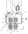
- FIG. 1 Fig. 3 is a plan view of a highly schematic system 10 for unmanned and fully automated picking according to the present invention.
- the system 10 may be constructed, for example, in a building (eg warehouse).
- the system 10 can be used as a storage and / or picking system.
- the system 10 here has a goods receipt area 12, a goods issue area or dispatch area 14, a storage area 16 and a first conveyor 18 in the form of a conveyor gyroscope 19.
- the first conveyor 18 may be realized in the form of eg roller conveyors, belt conveyors, chain conveyors, etc.
- the first conveyor 18 is over branch lines 20, which in the Fig. 1 are indicated in the form of double arrows, directly connected to the storage area 16.
- the conveyor technology sections 20, which function here as infeed and outfeed stitches can be of the same conveyor type as the first conveyor system 18.
- the gyro 19 can also be dissolved and replaced by individual conveyor connections between the individual system components.
- the conveyor system 18 could start, for example, in goods receipt 12 and end in goods issue 14, without goods receipt 12 and goods issue 14 being connected to each other via a conveyor system.
- the storage area 16 can, however, also be connected directly to the goods entrance 12 via a further conveyor 22, in order to be loaded with loading aids, such as e.g. Trays, containers, etc., not cumbersome and long to lead over the gyro 19, the gyro 19 itself can be directly connected via a further conveyor technology section 24 with the goods receipt 12.
- the gyro 19 may also be connected directly to the goods outlet 14, e.g. Storage containers can be sent from the storage area 16 directly to the shipping 14, without a picking (implementation of articles) is required. This may be the case, in particular, for large lots of a similar article type, e.g. entire pallets, containers or trays are ordered with articles of the same type.
- the goods receipt 12 and the goods issue can be directly connected to each other, as indicated by an arrow 28 with a dashed line.
- the gripping unit 30 engages articles that are either directly on the conveyor 18 or are stored in or on loading equipment, the loading equipment itself turn on the first conveyor technology.
- the gripping unit 30 is preferably mounted stationary on a building ceiling. Optionally, it is mounted above the first conveyor 18 on a frame (not shown).
- the gripping unit 30 grips articles and implements them.
- the articles are transferred to or dropped onto a second conveyor 32, eg, another conveyor.
- the second conveyor 32 couples to a plurality of job load aids, such as order containers 34, which may be cached in a job loader buffer 35.
- the buffer 35 is adjacent in the Fig. 1 directly to the second conveyor 32.
- the order loading aids 34 can in turn be transported into the dispatch area 14.
- Warehoused storage load aids are transported back to the storage area 16 or, if they are emptied, back into the goods receipt 12 after passing through the gripping unit 30.
- a unmanned, fully automated picking station is edged.
- the picking station 37 has at least the gripping unit 30.
- the picking station 37 may also have the first conveyor 18, the second conveyor 32 and the order load support buffer 35.
- the heart of the present invention is in the form of the gripping unit 30 in the Fig. 2 schematized shown in a perspective side view.
- the gripper unit 30 has a housing 40 in which a plurality of arms 42 are mounted. In the Fig. 2 For example, three arms 42 are shown.
- the arms 42 are constructed here by way of example in two parts, wherein the members are rotatably connected to each other by means of joints 44.
- the arms 42 are rotatably mounted in the housing 40.
- Opposite ends of the arms 42 are pivotally connected to a gripper 46, which in turn here by way of example two mechanical gripping tongs 48th having.
- Other gripper types, such as pneumatic suction devices, may also be used.
- a fourth arm 50 in the form of a rotary rod 50 is connected to the gripper 46.
- the rotary rod 50 is rotatable about its longitudinal axis, as indicated by a round double arrow.
- a fourth degree of freedom rotation about the Z-axis
- gripped articles are rotatable about a Z-axis.
- the number of degrees of movement could be increased by appropriate precautions. However, this would require additional mechanical elements which would limit the weight, and thus the speed with which the gripper 46 could be moved.
- the gripping unit 30 is able to move individual objects or articles, which can be arbitrarily selected from an article flow (loading aids or article heaps or groups), particularly quickly and precisely from one location to another location.
- An outstanding feature is the speed of the gripping unit 30, thanks to which the gripping unit 30 can provide up to 150 gripping and transfer cycles per minute. High web speeds and excellent positional accuracy are ensured. Appropriate control software enables the gripper unit 30 to follow high-speed conveyor techniques 18 with high accuracy.
- the housing 40 can be mounted either directly on a building ceiling or on a frame such that the first conveyor 18 (cf. Fig. 1 ) can be passed without problems under the gripping unit 30.
- the first conveyor 18 cf. Fig. 1
- the housing 40 can be mounted either directly on a building ceiling or on a frame such that the first conveyor 18 (cf. Fig. 1 ) can be passed without problems under the gripping unit 30.
- the first conveyor 18 cf. Fig. 1
- the gripping unit 30 has a radius of movement of preferably up to 1500 mm, with maximum accelerations of 10 g are possible.
- the greit unit 30 can lift articles of up to 2 kg.
- a control unit 31 may be integrated, which in the Fig. 3 is indicated by a rectangular box from a dashed line.
- the gripping unit 30 is preferably arranged centrally relative to a longitudinal axis of the first conveyor 18, in order to be able to access a maximum area on the first conveyor 18.
- the gripping unit 30 has a virtually circular working area 54.
- the working area 54 represents such positions in space that the gripper 46 (see FIG Fig. 2 ) can reach at maximum extended position of the arms 42.
- the overlapping region of the working area 54 with the first conveyor 18 represents a gripping area 56, which in the Fig. 3 also surrounded by a dashed line.
- the gripping area 56 is similar to a circle, which has been trimmed laterally by two circle segments.
- Fig. 3 Within the right circle segment there are in the Fig. 3 an overlapping area of the working area 54 with the second conveyor 32, which serves for the removal of converted articles 52, 52 ', 52 " Fig. 3 hatched drawn and is designated by the reference numeral 58. It represents a dispensing area 58. Within the dispensing area 58, a delivery point 60 is shown by means of a dashed line, the area of which substantially coincides with the area of an article 52 which is still on the first conveyor 18 within a receiving point 62 also indicated by a dashed line located. If in the following of dispensing or receiving points is spoken, so can so that a surface be meant.
- the article 52 may be, for example, a drug package.
- the gripping unit 30 grips the cuboid article 52 from the receiving point 52, while the first conveyor 18 moves continuously. Once the article 52 is gripped, the gripping unit 30 moves the article 52 out of the gripping area 56 into the storage area 58 and places the article 52 in the delivery point 60 on the second conveyor 32, which is oriented perpendicular to the first conveyor 18. Side of the second conveyor 32 are both left and right a plurality of order containers 34 are arranged, which are cached in buffers 35.
- the second conveyor 32 is realized here in the form of another belt conveyor, which is moved discretely or continuously in the direction of an arrow 64. Subsequently, it is assumed that the belt conveyor 32 is moved continuously in order to keep the throughput as high as possible.
- Each order container 34 is a discharge device 66, here exemplified in the form of a T-shaped slide assigned.
- a superordinated material flow computer or warehouse management computer 69 coordinates the discharge of the article 52 located on the second conveyor 32 into one of the order containers 34 by actuating an associated slider 66.
- the assignment of the article 52 to one of the order containers 34 has already been made in advance and deposited in the computer 69 , A conveyor technology for the removal of in the Fig. 3 Order container 34 shown on the right is not shown for reasons of clarity.
- a conveyor system 36 for delivery and removal of order containers 34 is in the left part of Fig. 3 indicated by a dashed line.
- order containers 34 can be transported into an order container buffer 35 ', which can optionally adjoin directly to the first conveyor 18 and which then lies in the working area 54 of the gripping unit 30.
- These order containers 34 are transferred between the buffer 35 'and the conveyor 36 by means of infeed / outfeed devices 68 (eg, belt ejectors, sliders, etc.).
- infeed / outfeed devices 68 eg, belt ejectors, sliders, etc.
- two order containers 34 of the buffer 35 ' are arranged within a further delivery area 58', which is likewise highlighted in hatched form. It is understood that with skillful placement or arrangement of the order container 34 of the buffer 35 ', more than two order containers 34 can be supplied simultaneously by the gripping unit 30 with articles 52, 52', 52 ".
- the left part of the Fig. 3 represents a modification opposite the right part of the Fig. 3
- the order containers 34 are placed directly in the working area 54 of the gripping unit 30.
- a sequencing stage (second conveyor 32) is eliminated. In order to shorten the time until an article is spent in its associated order container 34.
- the conveyor system 36 could also run directly adjacent parallel or obliquely to the first conveyor 18. In the case of a parallel arrangement can save the input / output devices 68, which in the Fig. 3 are illustrated in the form of double arrows. If the movement processes are suitably coordinated, the order containers 34 or the conveyor system 36 need not be stopped while the working area 54 or the delivery area 58 'of a gripping unit 30 is passed. The gripping unit 30 may deliver the articles directly into the order containers 34, of course assuming that they are so-called "dropable" articles. Fragile items should not be picked in this way. As regards the arrangement of the individual components (conveying techniques 18, 32) in the vertical direction, will be discussed in more detail below.
- the second conveyor 32 is to be arranged almost at the same level as the first conveyor 58.
- the order load conveyor conveyor 36 is disposed at such a level relative to the first conveyor 18 that an upper edge of an order container 34 in the buffer 35 'is at the same height as or below the first conveyor 18.
- Such a vertical arrangement is recommended because the lifting unit 30 in its usual embodiment has only a relatively small stroke, but achieved very high speeds in the horizontal direction of movement.
- the gripping unit 30 and the gripper 46 (see Fig. 2 ), which may also be in the form of a pneumatic nipple, can be accelerated with up to 10 g.
- an additional vertical lifting unit is mounted at the lower end of the arms 42 in the region of the gripper 46 in order to be able to generate an additional stroke.
- the gripper 46 is then preferably in the form of a pneumatic nipple.
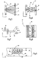
- Fig. 4 is a plan view of another embodiment of a picking system 10 'according to the present invention shown.
- two gripping units 30 are arranged serially one behind the other to unload load carriers 70, 72 or to grasp articles directly on the first conveyor 58, as shown at 74, and to translate them to second conveyor techniques 32.
- the storage load supports 70, 72 and an article accumulation 74 are transported on the first conveyor 18 counterclockwise from the goods receipt 12 or the warehouse 16 to the gripping units 30, as shown by an arrow 53.
- an image recognition unit 38 is preferably arranged in each case.
- the image recognition unit 38 can be designed in the form of a camera system that is arranged above the first conveyor 18 and looks down onto the conveyor 18.
- illuminants can be provided below a conveying means (e.g., belt) of the first conveyor, it being then advisable to make the conveying means of the first conveyor 18 translucent.
- the resolution or the contrast can be increased such that an object recognition software itself chaotically arranged articles, such as. may be present in the accumulation 74, with respect to their position and orientation relative to the first conveyor 18 can determine.
- Corresponding software packages are commercially available. The same applies to the camera system.
- Each of the two gripping units 30 of Fig. 4 preferably supplies two secondary conveyor techniques 32 with articles arranged perpendicular to the first conveyor 18.
- Each side of the second conveyor techniques 32 a buffer 35 for one or a plurality of order loading aids, here order container 34, is provided. Conveying techniques with which the order container 34 are transported into the buffer 35 and are transported from the buffers 35 to a goods outlet, not shown here, are not shown for reasons of clarity.
- the discharge devices 66 which are shown by way of example only in the left, second conveyor 32 of the upper fully automated and unmanned picking with the first gripping unit 30.
- the second conveyor techniques 32 are arranged here at the same height as the first conveyor 18. With the in the Fig. 4 As shown, up to forty picking orders can be processed in parallel since each of the buffers 35 has five target locations at which the order containers 34 can be positioned.
- the order loading means 34 could also be transported parallel to the first conveyor 18 in the area of the gripping units 30, preferably at the same speed as the articles on the first conveyor 18. In this case, picking orders could be processed serially by the two gripping units 30.
- the in the Fig. 4 The gripping unit 30 shown above could, in a first cycle, feed all articles from the first conveyor 18 into an order loader 34 which would then be positioned relative to the first conveyor 18 such that the upper edge of the order loader 34 is either at the same height as a top of the first conveyor 18 or less. All articles which the first upper gripping unit 30 fails to create because the articles leave the gripping area can subsequently be transferred from the second gripping unit 30 into the parallel-carried order loading aid 34.
- the bearing 16 is in the Fig. 4 partially cut open.
- a rack aisle 75 is shown, in which a storage and retrieval unit 76 can move along the rack aisle and vertically on the front of the shelf.
- the storage and retrieval unit 76 may have two load handling devices in order to be able to transport two loading aids (container and / or tray) at the same time.
- containers 70 are stored in the upper shelf.
- shelves 72 are stored in the lower shelf.
- FIG. 5 a plan view of isolated parts of a further modification is shown.
- the Fig. 5 shows a gripping unit 30 which is disposed above a first conveyor 18 and which can provide a plurality of webs 78 with articles.
- the left ends of the conveyor tracks 78 all end in the working area of the gripping unit 30.
- the opposite ends of the conveyor track 78 terminate at destination points 81, which are arranged here by a conveyor 36 for order containers 34. It is possible that at each of the gripping unit 30 opposite end of the conveyor tracks 78, an order container 34 is positioned at a target point 81, one of which in the Fig. 5 indicated by a dashed line.
- the conveyor tracks 78 may be e.g. to act driven roller conveyors or straps.
- gravity tracks may be used, e.g. in the form of, with respect to a horizontal, slanted slide plate or in the form of, with respect to a horizontal, inclined Losrollenbahn can be formed.
- FIG. 6 a further modification is shown in a plan view.
- a gripping unit 30 is arranged above a first conveyor 18.
- Side of the first conveyor 18 a plurality of accumulation conveyors 80, here a total of five accumulation conveyor 80, coupled to the first conveyor 18.
- the opposite ends of the accumulation conveyor 80 also couple to a conveyor 36 for order containers 34th
- the length of the accumulation conveyor is arbitrary. If the accumulation conveyor 80 are sufficiently long, in each case a liftable and lowerable stop 82 can be provided in the middle thereof, as in Fig. 6 is indicated by a dashed line to divide the accumulation conveyor into several sections or tracks.
- Fig. 6 five parallel adjacent accumulation conveyor are shown, which are divided by the stop 82 in a total of ten storage sections. These ten jam sections are shown in circles with the passing numbers from 0 to 9.
- Articles that are delivered via the first conveyor 18 to the gripping unit 30 can be transferred depending on order picking in one of the five accumulation conveyor 50. It is understood that the accumulation conveyor 80 all have an end which lies in the working area of the gripping unit 30.
- the corresponding stop member 82 of this accumulation conveyor 80 can be raised so as to provide the second jam section for another order picking.
- Ready picked orders can then be accessed and picked up by passing order containers 34.
- FIG. 7 a side view of another embodiment is shown.
- a gripping unit 30 which in turn is arranged above a first conveyor 18, here three secondary conveyor techniques 32-1, 32-2 and 32-3 are arranged vertically one above the other.
- a conveyor 36 for order container 34 is arranged at its gripping unit 30.
- the three conveyor techniques 32-1 to 32-3 are arranged such that arise in the delivery area of the gripping unit 30 vertical dispensing windows, which in the Fig. 7 are indicated by vertical dashed lines.
- the gripper unit 30 To provide articles to the upper conveyor 32-1, the gripper unit 30 must be moved furthest in the X direction. In order to supply articles to the lowermost conveyor system 32-3, the gripping unit 30 has to travel the shortest path in the X direction.
- the middle conveyor 32-3 requires movement of the gripper unit 30 in a central area in the X direction.
- the conveyor techniques 32-1 to 32-3 are driven here to load the articles in the Fig. 7 from left to right in the direction of the order container 34 to move. It It goes without saying that gravity railways can also be used here in order to be able to dispense with a drive.
- the secondary conveyor techniques 32 may further be arranged in the horizontal at an angle to each other, as in the Fig. 5 already shown for the gravity conveyor 78.
- the second conveyor techniques 32 of Fig. 7 Alternatively, they can be arranged in parallel next to each other in larger numbers, as in Fig. 6 is shown.
- a tray 72 is shown as being used to present the full range of articles to the gripper unit 30 in one hour, as discussed above.
- the tray 72 has a circumferential border 90. In the interior of the tray 72 can be provided in the longitudinal direction compartment partitions 92, for example, to define four tablet rows.
- the left tray series is fully stocked with articles 52.
- the subsequent tray series 94 has only one article 52 '.
- the second tray row from the right is itself subdivided into a plurality of tray individual compartments 98 with the aid of further compartment subdivisions 96. Some of these single shelves 98 are equipped with articles 52 " Fig. 8 tray series 94 'shown on the right is empty.
- Fig. 9 will be explained how to use without image recognition unit 38 (in contrast to the Fig. 1 and 4 ) can nevertheless safely and reliably grasp articles from the first conveyor 18 by means of the gripping unit 30.
- imaginary windows 100 are defined on the first conveyor 18 in the control unit.
- the imaginary windows 100 are formed by imaginary fields 102, which in turn are bounded by imaginary halftone dots 104 in their corners.
- the articles 52 are preferably applied individually to appropriately designed article trays 106, 108 set.
- the base area of the article trays 106, 108 preferably corresponds substantially to the base area of the different article types 52, 52 '.
- a cuboid 52 and two cubes 52 ' are each provided on a separate tray 106 and 108, respectively.
- the trays 106, 108 are aligned at the grid points 104 and placed on the grids 102.
- This process takes place, for example, in the area of the goods receipt 12 and / or of the warehouse 16.
- Loading devices provided for this purpose are controlled by the higher-level control unit 69 in such a way that the trays 106, 108 are placed on the grids provided for this purpose.
- the gripping unit 30 thus has absolute position data of the articles 52, 52 'relative to the first conveyor 18. Since the articles 52, 52' are each on a separate loading means 106, 108, it is for the gripper 46, in this case in shape is formed by mechanical pliers, irrelevant which type of article is actually stored on the loading aid 106, 108. A separation of the articles 52, 52 'from the loading equipment 106, 108 takes place at a later date.
- FIG. 10 a flowchart of a method is shown.
- a gripping unit 30 is provided in a first step S1.
- an article stream is conveyed to the gripping unit 30 via the first conveyor 18.
- the gripping unit 30 picks individual predetermined articles from the stream and places them in the delivery area, the gripping unit operating at a rate of up to 1500 items per hour or even up to 4000 items per hour.
- Returned goods are item shipments that are returned by the customer and then have to be returned to the warehouse. Returns consignments are characterized by the fact that many different items are usually contained in small numbers.
- the items of the return shipment can be given to the first conveyor and promoted as a group to a gripping unit.
- An image recognition unit located downstream of the gripping unit captures an image. With appropriate contour resolution algorithms, the positions and orientations of the individual articles can be resolved. This in turn generates control data for the gripping unit, which makes it possible to grasp the articles safely and reliably, even during a continuous conveying operation of the first conveyor system.
- scrapers can be used to break up the stacks and thus produce a single layer of articles.
- a scraper brush-like devices can be used, which are arranged horizontally at sometimes different heights across the first conveyor. It is understood that such stack-dissolving devices can of course also be used when picking normal items, especially when the gripping unit engages directly from the first conveyor, and thus not from loading equipment.
- these articles can be passed to specific article identification devices to be identified in terms of article type. Identified items can be cached until the parent machine has fetched the correct storage bin to then place the cached item into a bin associated with its item type.
Priority Applications (2)
| Application Number | Priority Date | Filing Date | Title |
|---|---|---|---|
| PL09777437T PL2315714T3 (pl) | 2008-08-29 | 2009-07-25 | Urządzenie do całkowicie zautomatyzowanego komisjonowania artykułów na zamówieniowych środkach ładunkowych |
| SI200930475T SI2315714T1 (sl) | 2008-08-29 | 2009-07-25 | Naprava za popolnoma avtomatizirano komisioniranje predmetov v pomoĹľnem nakladalnem sredstvu naloga |
Applications Claiming Priority (2)
| Application Number | Priority Date | Filing Date | Title |
|---|---|---|---|
| DE102008046325A DE102008046325A1 (de) | 2008-08-29 | 2008-08-29 | Verfahren und Vorrichtung zum mannlosen, vollautomatisierten Kommissionieren von Artikeln in Auftragsladehilfsmittel |
| PCT/EP2009/005400 WO2010022832A1 (de) | 2008-08-29 | 2009-07-25 | Verfahren und vorrichtung zum mannlosen, vollautomatisierten kommissionieren von artikeln in auftragsladehilfsmittel |
Publications (2)
| Publication Number | Publication Date |
|---|---|
| EP2315714A1 EP2315714A1 (de) | 2011-05-04 |
| EP2315714B1 true EP2315714B1 (de) | 2012-10-17 |
Family
ID=41315363
Family Applications (1)
| Application Number | Title | Priority Date | Filing Date |
|---|---|---|---|
| EP09777437A Not-in-force EP2315714B1 (de) | 2008-08-29 | 2009-07-25 | Vorrichtung zum vollautomatisierten kommissionieren von artikeln in auftragsladehilfsmittel |
Country Status (8)
| Country | Link |
|---|---|
| US (1) | US20110170998A1 (es) |
| EP (1) | EP2315714B1 (es) |
| BR (1) | BRPI0925345A2 (es) |
| DE (1) | DE102008046325A1 (es) |
| ES (1) | ES2396167T3 (es) |
| PL (1) | PL2315714T3 (es) |
| SI (1) | SI2315714T1 (es) |
| WO (1) | WO2010022832A1 (es) |
Cited By (4)
| Publication number | Priority date | Publication date | Assignee | Title |
|---|---|---|---|---|
| US9452894B2 (en) | 2013-04-09 | 2016-09-27 | Knapp Ag | Storage and order-picking system for the fully-automated identification and picking of articles |
| US10962963B2 (en) | 2016-01-14 | 2021-03-30 | Magazino Gmbh | Robot to pick up and transport objects and method using such a robot |
| EP4194376A1 (de) | 2018-03-09 | 2023-06-14 | TGW Logistics Group GmbH | Kommissionierstation und verfahren zum automatischen kommissionieren von waren |
| DE102022109603A1 (de) | 2022-04-21 | 2023-10-26 | Bayerische Motoren Werke Aktiengesellschaft | Verfahren zum Übergeben wenigstens eines Objekts sowie Transportvorrichtung |
Families Citing this family (28)
| Publication number | Priority date | Publication date | Assignee | Title |
|---|---|---|---|---|
| EP2184653A1 (fr) | 2008-11-06 | 2010-05-12 | Montres Breguet S.A. | Spiral à élévation de courbe en matériau micro-usinable |
| DE102009038124A1 (de) | 2009-08-17 | 2011-02-24 | SSI Schäfer PEEM GmbH | Lager- und Kommissioniersystem mit einem universell einsetzbaren Winkelladungsträger |
| DE102009042161B4 (de) | 2009-09-11 | 2016-09-22 | SSI Schäfer PEEM GmbH | Ladehilfsmittel mit konvex gewölbtem Boden, Einsatz für ein Ladehilfsmittel, Kommissioniersystem und Kommissionierverfahren |
| DE102009052345B4 (de) | 2009-10-30 | 2013-02-28 | SSI Schäfer PEEM GmbH | Automatisierte Kommissioniervorrichtung und Verfahren zum automatisierten Kommissionieren von Büchern, Medien, Prospekten und ähnlichen Gegenständen |
| CN101708611B (zh) * | 2009-11-09 | 2011-07-27 | 天津大学 | 一种具有三维平动一维转动的并联机构 |
| DE102010015414A1 (de) * | 2010-04-19 | 2011-10-20 | Siemens Aktiengesellschaft | Kommissionieranlage und Verfahren zum Kommissionieren von Packstücken |
| AT509950B1 (de) | 2010-06-01 | 2013-01-15 | Knapp Ag | Lager- und kommissioniersystem |
| ITTO20110405A1 (it) * | 2011-05-06 | 2012-11-07 | Opm S P A | Impianto di trasferimento per trasferire prodotti tra due linee di trasporto parallele tramite una serie di robot |
| AT511558B1 (de) * | 2011-05-30 | 2013-04-15 | Knapp Ag | Knickarmgreifer |
| DE102011104511B3 (de) | 2011-06-15 | 2012-10-25 | SSI Schäfer PEEM GmbH | Distributionslager und Verfahren zum auftragsorientierten Zusammenstellen von verschiedenen Artikeln mit einem reduzierten Puffer |
| DE102011052193A1 (de) | 2011-07-27 | 2013-01-31 | Dematic Gmbh | Verfahren zum Lagern und Kommissionieren |
| DE102012006150A1 (de) | 2012-03-28 | 2013-10-02 | Knapp Ag | Zentralbandsystem einer Kommissionieranlage |
| EP2818433B1 (de) | 2013-06-25 | 2016-08-10 | SSI Schäfer Peem GmbH | Automatisierte Kommissionierzelle und Verfahren zum automatisierten Kommissionieren von A+-Stückgütern |
| GB201402263D0 (en) * | 2014-02-10 | 2014-03-26 | Ocado Ltd | Intermediate holding facility for picking station |
| JP6387760B2 (ja) * | 2014-09-18 | 2018-09-12 | 株式会社安川電機 | ロボットシステム、ロボット装置およびワークピッキング方法 |
| GB201601880D0 (en) * | 2016-02-02 | 2016-03-16 | Ocado Innovation Ltd | Robotic gripping device system and method |
| DE102016107268B4 (de) | 2016-04-20 | 2022-02-10 | Ssi Schäfer Automation Gmbh | Mehrarm-Roboter für komplexe Kommissionieraufgaben |
| EP3458385A1 (de) | 2016-05-17 | 2019-03-27 | Liebherr-Verzahntechnik GmbH | Kommissioniersystem |
| WO2017198281A1 (de) | 2016-05-17 | 2017-11-23 | Liebherr-Verzahntechnik Gmbh | Kommissionierzelle |
| JP6370842B2 (ja) * | 2016-06-29 | 2018-08-08 | ファナック株式会社 | 仮置き部を備えた物品搬送装置 |
| US10246258B2 (en) * | 2016-10-17 | 2019-04-02 | Amazon Technologies, Inc. | Robotic item sortation and optimization along the vertical axis |
| AT520005A1 (de) * | 2017-06-02 | 2018-12-15 | Tgw Logistics Group Gmbh | Verfahren und Warenlagersystem zum Kommissionieren von Waren mit effizient betriebenem dynamischen Puffer |
| KR102617249B1 (ko) * | 2017-11-21 | 2023-12-21 | 풀필 솔루션스, 인크. | 제품 핸들링 및 포장 시스템 |
| EP3738719B1 (de) | 2019-05-13 | 2024-05-01 | IGZ Ingenieurgesellschaft für logistische Informationssysteme mbH | Mobiler kommissionierroboter, ware-zur-person kommissionierarbeitsplatz und kommissioniersystem |
| TWI700129B (zh) * | 2019-07-24 | 2020-08-01 | 開必拓數據股份有限公司 | 基於自我學習技術之移動物品分類系統及方法 |
| DE102019135445B3 (de) * | 2019-12-20 | 2021-03-11 | IGZ Ingenieurgesellschaft für logistische Informationssysteme mbH | Reichweiten-Verlängerung für Roboter-Kommissioniersysteme |
| EP4114769A1 (en) * | 2020-03-06 | 2023-01-11 | Berkshire Grey Operating Company, Inc. | Systems and methods for providing order fulfillment using a spiral tower system |
| DE102021121483A1 (de) * | 2021-08-19 | 2023-02-23 | Krones Aktiengesellschaft | Ausleitsystem und Ausleitverfahren für Behältnisse mittels Tripod-Roboter |
Family Cites Families (33)
| Publication number | Priority date | Publication date | Assignee | Title |
|---|---|---|---|---|
| US3844422A (en) * | 1969-12-29 | 1974-10-29 | I Smith | Pallet loading machine |
| DE2062845A1 (de) * | 1970-12-21 | 1972-07-06 | Pierau E | Kommissionierungseinrichtung |
| US4641271A (en) * | 1983-11-09 | 1987-02-03 | Hitachi, Ltd. | Piling planning method and piling system of cargoes by palletizing robot |
| DE3408081A1 (de) * | 1984-03-05 | 1985-09-19 | Siemens AG, 1000 Berlin und 8000 München | Kommissioniereinrichtung |
| JPS61134808A (ja) * | 1984-12-05 | 1986-06-21 | Mitsubishi Electric Corp | 産業用ロポツト装置 |
| US4896087A (en) * | 1989-01-31 | 1990-01-23 | Staubli International Ag. | Robotic workcell control system having improved input/output interfacing for better workcell operation |
| US5175692A (en) * | 1989-04-14 | 1992-12-29 | University Of Cincinnati | Method and apparatus for palletizing randomly arriving mixed size and content parcels |
| DE3926261C1 (es) * | 1989-08-09 | 1990-05-10 | Ostma Maschinenbau Gmbh, 5352 Zuelpich, De | |
| GB2236409B (en) * | 1989-08-31 | 1993-11-10 | Mitsubishi Electric Corp | Industrial robot apparatus |
| US5281081A (en) * | 1990-01-10 | 1994-01-25 | Mitsubishi Denki Kabushiki Kaisha | Stowage device for plural species of works |
| US5040056A (en) * | 1990-01-29 | 1991-08-13 | Technistar Corporation | Automated system for locating and transferring objects on a conveyor belt |
| DE4114215A1 (de) * | 1991-05-01 | 1992-11-05 | Focke & Co | Einrichtung zum beladen von paletten mit kartons |
| IT1245912B (it) * | 1991-05-22 | 1994-10-25 | Gd Spa | Impianto per la pallettizzazione selettiva di articoli di diverse caratteristiche. |
| JP2987053B2 (ja) | 1994-05-10 | 1999-12-06 | オークラ輸送機株式会社 | ピッキング装置 |
| US5873214A (en) * | 1996-11-15 | 1999-02-23 | Lantech, Inc. | Method and apparatus for load building and stretch wrapping |
| DE29701564U1 (de) * | 1997-01-30 | 1997-03-27 | Schubert Gerhard Gmbh | Pickerstraße mit entgegengesetztem Traytransport |
| US6011998A (en) * | 1997-05-09 | 2000-01-04 | Lichti; Wayne | High speed picking system |
| DE19815434A1 (de) * | 1998-04-07 | 1999-10-14 | Focke & Co | Hubvorrichtung (Palettierer) mit Schwenkarm |
| DE19820537C2 (de) * | 1998-05-08 | 2000-08-10 | Rudolf Kerler | Verfahren und Vorrichtung zum Verpacken und Sortieren von länglichen Gegenständen |
| US6626632B2 (en) * | 1999-12-03 | 2003-09-30 | Motoman, Inc. | Robotic order picking system |
| DE10119679B4 (de) * | 2001-04-20 | 2005-06-30 | Flexlink Systems Gmbh | Einrichtung zum Kommissionieren und/oder Palettieren von Stückgütern und Verfahren hierzu |
| US6711880B2 (en) * | 2001-05-23 | 2004-03-30 | Sig Pack Systems Ag | Apparatus for, and method of, feeding piece goods to a tubular-bag packaging station |
| MXPA03011877A (es) * | 2001-06-07 | 2004-06-03 | Siemens Ag | Arquitectura de control escalonado para manejar materiales. |
| SE525605C2 (sv) * | 2002-04-24 | 2005-03-22 | Abb Ab | Förpackningsmaskin |
| PL1685045T5 (pl) * | 2003-10-28 | 2015-05-29 | Aew Delford Systems Ltd | Usprawniony chwytak zdejmująco-układający |
| US7266422B1 (en) * | 2004-04-09 | 2007-09-04 | Fanuc Robotics America, Inc. | Automated palletizing cases having mixed sizes and shapes |
| US8418830B2 (en) * | 2005-11-10 | 2013-04-16 | Mi Robotic Solutions (Mirs) | Robot system and method for removing sticks and/or foreign elements from conveyor belts |
| US20070280814A1 (en) * | 2006-05-17 | 2007-12-06 | Axium Inc. | System and method to build mixed pallet layers from full pallet layers |
| DE102006024900A1 (de) | 2006-05-24 | 2007-11-29 | WINKLER + DüNNEBIER AG | Vorrichtung und Verfahren zum Handhaben von Paletten in- und außerhalb einer Palettierzelle |
| BRPI0621882B1 (pt) * | 2006-07-17 | 2019-03-26 | A. Celli Nonwovens S.P.A | Sistema automatizado para a produção e manejo de rolos de material de manta e robô destinado especialmente para o dito sistema |
| WO2009011634A1 (en) * | 2007-07-13 | 2009-01-22 | Lars Erik Trygg | Apparatus and method for grouping units |
| CA2639259C (en) * | 2007-09-07 | 2014-03-11 | Dematic Corp. | Conveyor systems |
| US8074431B1 (en) * | 2009-06-01 | 2011-12-13 | Top Tier, Inc. | Hybrid palletizer |
-
2008
- 2008-08-29 DE DE102008046325A patent/DE102008046325A1/de not_active Withdrawn
-
2009
- 2009-07-25 PL PL09777437T patent/PL2315714T3/pl unknown
- 2009-07-25 ES ES09777437T patent/ES2396167T3/es active Active
- 2009-07-25 EP EP09777437A patent/EP2315714B1/de not_active Not-in-force
- 2009-07-25 SI SI200930475T patent/SI2315714T1/sl unknown
- 2009-07-25 WO PCT/EP2009/005400 patent/WO2010022832A1/de active Application Filing
- 2009-07-25 BR BRPI0925345A patent/BRPI0925345A2/pt not_active Application Discontinuation
-
2010
- 2010-12-23 US US12/978,040 patent/US20110170998A1/en not_active Abandoned
Cited By (5)
| Publication number | Priority date | Publication date | Assignee | Title |
|---|---|---|---|---|
| US9452894B2 (en) | 2013-04-09 | 2016-09-27 | Knapp Ag | Storage and order-picking system for the fully-automated identification and picking of articles |
| US10962963B2 (en) | 2016-01-14 | 2021-03-30 | Magazino Gmbh | Robot to pick up and transport objects and method using such a robot |
| EP4194376A1 (de) | 2018-03-09 | 2023-06-14 | TGW Logistics Group GmbH | Kommissionierstation und verfahren zum automatischen kommissionieren von waren |
| EP4201852A1 (de) | 2018-03-09 | 2023-06-28 | TGW Logistics Group GmbH | Kommissionierstation zum automatischen kommissionieren von waren |
| DE102022109603A1 (de) | 2022-04-21 | 2023-10-26 | Bayerische Motoren Werke Aktiengesellschaft | Verfahren zum Übergeben wenigstens eines Objekts sowie Transportvorrichtung |
Also Published As
| Publication number | Publication date |
|---|---|
| US20110170998A1 (en) | 2011-07-14 |
| PL2315714T3 (pl) | 2013-03-29 |
| WO2010022832A1 (de) | 2010-03-04 |
| EP2315714A1 (de) | 2011-05-04 |
| SI2315714T1 (sl) | 2013-02-28 |
| DE102008046325A1 (de) | 2010-03-11 |
| BRPI0925345A2 (pt) | 2016-04-26 |
| WO2010022832A8 (de) | 2010-04-29 |
| ES2396167T3 (es) | 2013-02-19 |
Similar Documents
| Publication | Publication Date | Title |
|---|---|---|
| EP2315714B1 (de) | Vorrichtung zum vollautomatisierten kommissionieren von artikeln in auftragsladehilfsmittel | |
| EP3330200B1 (de) | Verfahren zum ein- und auslagern von gegenständen sowie lagersystem zur durchführung des verfahrens | |
| EP2139793B1 (de) | Automatisiertes kommissioniersystem mit integrierter sortierfunktion und verfahren zum betreiben desselben | |
| DE102006057758B4 (de) | Verfahren und Vorrichtung zum Kommissionieren von Waren und Lagerverwaltungssystem | |
| EP2019798B1 (de) | Verfahren zum betreiben einer kommissionieranlage | |
| EP2297005B1 (de) | Lagersystem und verfahren zum betreiben desselben | |
| EP2032472B1 (de) | Regal-integrierte packstation und kommissionierverfahren | |
| AT518818B1 (de) | Verfahren zum Kommissionieren von Artikeln und Kommissionierstation | |
| EP1073598B1 (de) | Vorrichtung zum behandeln von flaschen | |
| DE102006025617B4 (de) | Arbeitsplatz und Verfahren zum Packen | |
| EP2976275B1 (de) | Automatisierter kommissionierplatz und entsprechendes verfahren | |
| EP3762319B1 (de) | Kommissionierstation und verfahren zum automatischen kommissionieren von waren | |
| DE102014104470A1 (de) | Stapelkommissionierung | |
| EP3889076B1 (de) | Kommissioniersystem und kommissionierverfahren | |
| EP0977695B1 (de) | Vorrichtung zum sammeln und palettieren von flaschen | |
| DE19712839A1 (de) | Kommissionierverfahren, Kommissionieranlage zur Durchführung des Verfahrens sowie Sortierpuffer hierfür | |
| EP2602213B1 (de) | Kombinierte Kommissionierung mit Kommissionierfahrzeugen und einer Lagendepalettiervorrichtung | |
| DE102009052345B4 (de) | Automatisierte Kommissioniervorrichtung und Verfahren zum automatisierten Kommissionieren von Büchern, Medien, Prospekten und ähnlichen Gegenständen | |
| EP3889077B1 (de) | Kommissioniersystem | |
| EP3459879A1 (de) | Roboterbasiertes lagersystem | |
| EP3592669B1 (de) | Verfahren zur auslagerung von waren aus einem lager zur auftragserfüllung | |
| EP2163492B1 (de) | Kombiniertes Warenlager | |
| WO2023095049A1 (de) | Vorrichtung zum beladungsmanagement von transporteinheiten eines fördersystems |
Legal Events
| Date | Code | Title | Description |
|---|---|---|---|
| PUAI | Public reference made under article 153(3) epc to a published international application that has entered the european phase |
Free format text: ORIGINAL CODE: 0009012 |
|
| 17P | Request for examination filed |
Effective date: 20101217 |
|
| AK | Designated contracting states |
Kind code of ref document: A1 Designated state(s): AT BE BG CH CY CZ DE DK EE ES FI FR GB GR HR HU IE IS IT LI LT LU LV MC MK MT NL NO PL PT RO SE SI SK SM TR |
|
| AX | Request for extension of the european patent |
Extension state: AL BA RS |
|
| 17Q | First examination report despatched |
Effective date: 20110823 |
|
| DAX | Request for extension of the european patent (deleted) | ||
| RTI1 | Title (correction) |
Free format text: DEVICE FOR FULLY AUTOMATED COMMISSIONING OF ARTICLES IN ORDER BEARING MEANS |
|
| GRAP | Despatch of communication of intention to grant a patent |
Free format text: ORIGINAL CODE: EPIDOSNIGR1 |
|
| GRAJ | Information related to disapproval of communication of intention to grant by the applicant or resumption of examination proceedings by the epo deleted |
Free format text: ORIGINAL CODE: EPIDOSDIGR1 |
|
| GRAP | Despatch of communication of intention to grant a patent |
Free format text: ORIGINAL CODE: EPIDOSNIGR1 |
|
| GRAS | Grant fee paid |
Free format text: ORIGINAL CODE: EPIDOSNIGR3 |
|
| GRAA | (expected) grant |
Free format text: ORIGINAL CODE: 0009210 |
|
| AK | Designated contracting states |
Kind code of ref document: B1 Designated state(s): AT BE BG CH CY CZ DE DK EE ES FI FR GB GR HR HU IE IS IT LI LT LU LV MC MK MT NL NO PL PT RO SE SI SK SM TR |
|
| REG | Reference to a national code |
Ref country code: GB Ref legal event code: FG4D Free format text: NOT ENGLISH |
|
| REG | Reference to a national code |
Ref country code: CH Ref legal event code: NV Representative=s name: WITTE, WELLER & PARTNER Ref country code: CH Ref legal event code: EP |
|
| REG | Reference to a national code |
Ref country code: IE Ref legal event code: FG4D Free format text: LANGUAGE OF EP DOCUMENT: GERMAN |
|
| REG | Reference to a national code |
Ref country code: AT Ref legal event code: REF Ref document number: 579806 Country of ref document: AT Kind code of ref document: T Effective date: 20121115 |
|
| REG | Reference to a national code |
Ref country code: DE Ref legal event code: R096 Ref document number: 502009005134 Country of ref document: DE Effective date: 20121213 |
|
| REG | Reference to a national code |
Ref country code: SE Ref legal event code: TRGR |
|
| REG | Reference to a national code |
Ref country code: NL Ref legal event code: T3 |
|
| REG | Reference to a national code |
Ref country code: ES Ref legal event code: FG2A Ref document number: 2396167 Country of ref document: ES Kind code of ref document: T3 Effective date: 20130219 |
|
| REG | Reference to a national code |
Ref country code: LT Ref legal event code: MG4D |
|
| REG | Reference to a national code |
Ref country code: PL Ref legal event code: T3 |
|
| PG25 | Lapsed in a contracting state [announced via postgrant information from national office to epo] |
Ref country code: IS Free format text: LAPSE BECAUSE OF FAILURE TO SUBMIT A TRANSLATION OF THE DESCRIPTION OR TO PAY THE FEE WITHIN THE PRESCRIBED TIME-LIMIT Effective date: 20130217 Ref country code: LT Free format text: LAPSE BECAUSE OF FAILURE TO SUBMIT A TRANSLATION OF THE DESCRIPTION OR TO PAY THE FEE WITHIN THE PRESCRIBED TIME-LIMIT Effective date: 20121017 Ref country code: HR Free format text: LAPSE BECAUSE OF FAILURE TO SUBMIT A TRANSLATION OF THE DESCRIPTION OR TO PAY THE FEE WITHIN THE PRESCRIBED TIME-LIMIT Effective date: 20121017 Ref country code: NO Free format text: LAPSE BECAUSE OF FAILURE TO SUBMIT A TRANSLATION OF THE DESCRIPTION OR TO PAY THE FEE WITHIN THE PRESCRIBED TIME-LIMIT Effective date: 20130117 Ref country code: FI Free format text: LAPSE BECAUSE OF FAILURE TO SUBMIT A TRANSLATION OF THE DESCRIPTION OR TO PAY THE FEE WITHIN THE PRESCRIBED TIME-LIMIT Effective date: 20121017 |
|
| PG25 | Lapsed in a contracting state [announced via postgrant information from national office to epo] |
Ref country code: LV Free format text: LAPSE BECAUSE OF FAILURE TO SUBMIT A TRANSLATION OF THE DESCRIPTION OR TO PAY THE FEE WITHIN THE PRESCRIBED TIME-LIMIT Effective date: 20121017 Ref country code: GR Free format text: LAPSE BECAUSE OF FAILURE TO SUBMIT A TRANSLATION OF THE DESCRIPTION OR TO PAY THE FEE WITHIN THE PRESCRIBED TIME-LIMIT Effective date: 20130118 Ref country code: PT Free format text: LAPSE BECAUSE OF FAILURE TO SUBMIT A TRANSLATION OF THE DESCRIPTION OR TO PAY THE FEE WITHIN THE PRESCRIBED TIME-LIMIT Effective date: 20130218 |
|
| PLBI | Opposition filed |
Free format text: ORIGINAL CODE: 0009260 |
|
| PLBI | Opposition filed |
Free format text: ORIGINAL CODE: 0009260 |
|
| PLAB | Opposition data, opponent's data or that of the opponent's representative modified |
Free format text: ORIGINAL CODE: 0009299OPPO |
|
| PG25 | Lapsed in a contracting state [announced via postgrant information from national office to epo] |
Ref country code: DK Free format text: LAPSE BECAUSE OF FAILURE TO SUBMIT A TRANSLATION OF THE DESCRIPTION OR TO PAY THE FEE WITHIN THE PRESCRIBED TIME-LIMIT Effective date: 20121017 Ref country code: CZ Free format text: LAPSE BECAUSE OF FAILURE TO SUBMIT A TRANSLATION OF THE DESCRIPTION OR TO PAY THE FEE WITHIN THE PRESCRIBED TIME-LIMIT Effective date: 20121017 Ref country code: EE Free format text: LAPSE BECAUSE OF FAILURE TO SUBMIT A TRANSLATION OF THE DESCRIPTION OR TO PAY THE FEE WITHIN THE PRESCRIBED TIME-LIMIT Effective date: 20121017 Ref country code: SK Free format text: LAPSE BECAUSE OF FAILURE TO SUBMIT A TRANSLATION OF THE DESCRIPTION OR TO PAY THE FEE WITHIN THE PRESCRIBED TIME-LIMIT Effective date: 20121017 Ref country code: BG Free format text: LAPSE BECAUSE OF FAILURE TO SUBMIT A TRANSLATION OF THE DESCRIPTION OR TO PAY THE FEE WITHIN THE PRESCRIBED TIME-LIMIT Effective date: 20130117 |
|
| 26 | Opposition filed |
Opponent name: KNAPP AG Effective date: 20130705 |
|
| 26 | Opposition filed |
Opponent name: VMT VISION MACHINE TECHNIC BILDVERARBEITUNGSSYSTEM Effective date: 20130716 |
|
| R26 | Opposition filed (corrected) |
Opponent name: VMT VISION MACHINE TECHNIC BILDVERARBEITUNGSSYSTEM Effective date: 20130716 |
|
| PG25 | Lapsed in a contracting state [announced via postgrant information from national office to epo] |
Ref country code: RO Free format text: LAPSE BECAUSE OF FAILURE TO SUBMIT A TRANSLATION OF THE DESCRIPTION OR TO PAY THE FEE WITHIN THE PRESCRIBED TIME-LIMIT Effective date: 20121017 |
|
| PLAX | Notice of opposition and request to file observation + time limit sent |
Free format text: ORIGINAL CODE: EPIDOSNOBS2 |
|
| REG | Reference to a national code |
Ref country code: DE Ref legal event code: R026 Ref document number: 502009005134 Country of ref document: DE Effective date: 20130705 |
|
| PGFP | Annual fee paid to national office [announced via postgrant information from national office to epo] |
Ref country code: SE Payment date: 20130719 Year of fee payment: 5 Ref country code: SI Payment date: 20130624 Year of fee payment: 5 |
|
| PG25 | Lapsed in a contracting state [announced via postgrant information from national office to epo] |
Ref country code: CY Free format text: LAPSE BECAUSE OF FAILURE TO SUBMIT A TRANSLATION OF THE DESCRIPTION OR TO PAY THE FEE WITHIN THE PRESCRIBED TIME-LIMIT Effective date: 20121017 |
|
| PGFP | Annual fee paid to national office [announced via postgrant information from national office to epo] |
Ref country code: PL Payment date: 20130628 Year of fee payment: 5 |
|
| PGFP | Annual fee paid to national office [announced via postgrant information from national office to epo] |
Ref country code: IT Payment date: 20130725 Year of fee payment: 5 |
|
| PLAF | Information modified related to communication of a notice of opposition and request to file observations + time limit |
Free format text: ORIGINAL CODE: EPIDOSCOBS2 |
|
| BERE | Be: lapsed |
Owner name: SSI SCHAFER PEEM GMBH Effective date: 20130731 |
|
| REG | Reference to a national code |
Ref country code: CH Ref legal event code: PFA Owner name: SSI SCHAEFER PEEM GMBH, AT Free format text: FORMER OWNER: SSI SCHAEFER PEEM GMBH, AT |
|
| PLBB | Reply of patent proprietor to notice(s) of opposition received |
Free format text: ORIGINAL CODE: EPIDOSNOBS3 |
|
| PG25 | Lapsed in a contracting state [announced via postgrant information from national office to epo] |
Ref country code: MC Free format text: LAPSE BECAUSE OF FAILURE TO SUBMIT A TRANSLATION OF THE DESCRIPTION OR TO PAY THE FEE WITHIN THE PRESCRIBED TIME-LIMIT Effective date: 20121017 |
|
| REG | Reference to a national code |
Ref country code: IE Ref legal event code: MM4A |
|
| PG25 | Lapsed in a contracting state [announced via postgrant information from national office to epo] |
Ref country code: BE Free format text: LAPSE BECAUSE OF NON-PAYMENT OF DUE FEES Effective date: 20130731 |
|
| PG25 | Lapsed in a contracting state [announced via postgrant information from national office to epo] |
Ref country code: IE Free format text: LAPSE BECAUSE OF NON-PAYMENT OF DUE FEES Effective date: 20130725 |
|
| REG | Reference to a national code |
Ref country code: SE Ref legal event code: EUG |
|
| PG25 | Lapsed in a contracting state [announced via postgrant information from national office to epo] |
Ref country code: IT Free format text: LAPSE BECAUSE OF NON-PAYMENT OF DUE FEES Effective date: 20140725 |
|
| REG | Reference to a national code |
Ref country code: SI Ref legal event code: KO00 Effective date: 20150317 |
|
| PG25 | Lapsed in a contracting state [announced via postgrant information from national office to epo] |
Ref country code: SM Free format text: LAPSE BECAUSE OF FAILURE TO SUBMIT A TRANSLATION OF THE DESCRIPTION OR TO PAY THE FEE WITHIN THE PRESCRIBED TIME-LIMIT Effective date: 20121017 Ref country code: SE Free format text: LAPSE BECAUSE OF NON-PAYMENT OF DUE FEES Effective date: 20140726 Ref country code: SI Free format text: LAPSE BECAUSE OF NON-PAYMENT OF DUE FEES Effective date: 20140726 |
|
| REG | Reference to a national code |
Ref country code: FR Ref legal event code: PLFP Year of fee payment: 7 |
|
| PG25 | Lapsed in a contracting state [announced via postgrant information from national office to epo] |
Ref country code: TR Free format text: LAPSE BECAUSE OF FAILURE TO SUBMIT A TRANSLATION OF THE DESCRIPTION OR TO PAY THE FEE WITHIN THE PRESCRIBED TIME-LIMIT Effective date: 20121017 Ref country code: MT Free format text: LAPSE BECAUSE OF FAILURE TO SUBMIT A TRANSLATION OF THE DESCRIPTION OR TO PAY THE FEE WITHIN THE PRESCRIBED TIME-LIMIT Effective date: 20121017 |
|
| PG25 | Lapsed in a contracting state [announced via postgrant information from national office to epo] |
Ref country code: MK Free format text: LAPSE BECAUSE OF FAILURE TO SUBMIT A TRANSLATION OF THE DESCRIPTION OR TO PAY THE FEE WITHIN THE PRESCRIBED TIME-LIMIT Effective date: 20121017 Ref country code: HU Free format text: LAPSE BECAUSE OF FAILURE TO SUBMIT A TRANSLATION OF THE DESCRIPTION OR TO PAY THE FEE WITHIN THE PRESCRIBED TIME-LIMIT; INVALID AB INITIO Effective date: 20090725 Ref country code: LU Free format text: LAPSE BECAUSE OF NON-PAYMENT OF DUE FEES Effective date: 20130725 |
|
| REG | Reference to a national code |
Ref country code: DE Ref legal event code: R100 Ref document number: 502009005134 Country of ref document: DE |
|
| REG | Reference to a national code |
Ref country code: PL Ref legal event code: LAPE |
|
| PLCK | Communication despatched that opposition was rejected |
Free format text: ORIGINAL CODE: EPIDOSNREJ1 |
|
| PG25 | Lapsed in a contracting state [announced via postgrant information from national office to epo] |
Ref country code: PL Free format text: LAPSE BECAUSE OF NON-PAYMENT OF DUE FEES Effective date: 20140725 |
|
| PLBN | Opposition rejected |
Free format text: ORIGINAL CODE: 0009273 |
|
| STAA | Information on the status of an ep patent application or granted ep patent |
Free format text: STATUS: OPPOSITION REJECTED |
|
| 27O | Opposition rejected |
Effective date: 20151001 |
|
| REG | Reference to a national code |
Ref country code: FR Ref legal event code: PLFP Year of fee payment: 8 |
|
| REG | Reference to a national code |
Ref country code: DE Ref legal event code: R081 Ref document number: 502009005134 Country of ref document: DE Owner name: SSI SCHAEFER AUTOMATION GMBH, AT Free format text: FORMER OWNER: SSI SCHAEFER PEEM GMBH, GRAZ, AT Ref country code: DE Ref legal event code: R082 Ref document number: 502009005134 Country of ref document: DE Representative=s name: WITTE, WELLER & PARTNER PATENTANWAELTE MBB, DE |
|
| REG | Reference to a national code |
Ref country code: FR Ref legal event code: PLFP Year of fee payment: 9 |
|
| PGFP | Annual fee paid to national office [announced via postgrant information from national office to epo] |
Ref country code: GB Payment date: 20170719 Year of fee payment: 9 Ref country code: CH Payment date: 20170719 Year of fee payment: 9 Ref country code: ES Payment date: 20170825 Year of fee payment: 9 Ref country code: FR Payment date: 20170724 Year of fee payment: 9 |
|
| REG | Reference to a national code |
Ref country code: CH Ref legal event code: NV Representative=s name: TROESCH SCHEIDEGGER WERNER AG, CH |
|
| PGFP | Annual fee paid to national office [announced via postgrant information from national office to epo] |
Ref country code: NL Payment date: 20180719 Year of fee payment: 10 |
|
| REG | Reference to a national code |
Ref country code: CH Ref legal event code: PL |
|
| GBPC | Gb: european patent ceased through non-payment of renewal fee |
Effective date: 20180725 |
|
| PG25 | Lapsed in a contracting state [announced via postgrant information from national office to epo] |
Ref country code: LI Free format text: LAPSE BECAUSE OF NON-PAYMENT OF DUE FEES Effective date: 20180731 Ref country code: GB Free format text: LAPSE BECAUSE OF NON-PAYMENT OF DUE FEES Effective date: 20180725 Ref country code: FR Free format text: LAPSE BECAUSE OF NON-PAYMENT OF DUE FEES Effective date: 20180731 Ref country code: CH Free format text: LAPSE BECAUSE OF NON-PAYMENT OF DUE FEES Effective date: 20180731 |
|
| REG | Reference to a national code |
Ref country code: ES Ref legal event code: FD2A Effective date: 20190917 |
|
| PG25 | Lapsed in a contracting state [announced via postgrant information from national office to epo] |
Ref country code: ES Free format text: LAPSE BECAUSE OF NON-PAYMENT OF DUE FEES Effective date: 20180726 |
|
| PG25 | Lapsed in a contracting state [announced via postgrant information from national office to epo] |
Ref country code: NL Free format text: LAPSE BECAUSE OF NON-PAYMENT OF DUE FEES Effective date: 20190801 |
|
| REG | Reference to a national code |
Ref country code: NL Ref legal event code: MM Effective date: 20190801 |
|
| PGFP | Annual fee paid to national office [announced via postgrant information from national office to epo] |
Ref country code: DE Payment date: 20200821 Year of fee payment: 12 |
|
| PGFP | Annual fee paid to national office [announced via postgrant information from national office to epo] |
Ref country code: AT Payment date: 20200722 Year of fee payment: 12 |
|
| REG | Reference to a national code |
Ref country code: DE Ref legal event code: R119 Ref document number: 502009005134 Country of ref document: DE |
|
| REG | Reference to a national code |
Ref country code: AT Ref legal event code: MM01 Ref document number: 579806 Country of ref document: AT Kind code of ref document: T Effective date: 20210725 |
|
| PG25 | Lapsed in a contracting state [announced via postgrant information from national office to epo] |
Ref country code: DE Free format text: LAPSE BECAUSE OF NON-PAYMENT OF DUE FEES Effective date: 20220201 Ref country code: AT Free format text: LAPSE BECAUSE OF NON-PAYMENT OF DUE FEES Effective date: 20210725 |