EP2315714B1 - Device for fully automated commissioning of articles in order bearing means - Google Patents
Device for fully automated commissioning of articles in order bearing means Download PDFInfo
- Publication number
- EP2315714B1 EP2315714B1 EP09777437A EP09777437A EP2315714B1 EP 2315714 B1 EP2315714 B1 EP 2315714B1 EP 09777437 A EP09777437 A EP 09777437A EP 09777437 A EP09777437 A EP 09777437A EP 2315714 B1 EP2315714 B1 EP 2315714B1
- Authority
- EP
- European Patent Office
- Prior art keywords
- conveyor
- articles
- gripping
- storage
- order
- Prior art date
- Legal status (The legal status is an assumption and is not a legal conclusion. Google has not performed a legal analysis and makes no representation as to the accuracy of the status listed.)
- Not-in-force
Links
- 239000000872 buffer Substances 0.000 claims description 21
- 238000009825 accumulation Methods 0.000 claims description 16
- 230000005484 gravity Effects 0.000 claims description 8
- 238000012546 transfer Methods 0.000 claims description 8
- 230000001133 acceleration Effects 0.000 claims description 4
- 238000011144 upstream manufacturing Methods 0.000 claims description 3
- 230000003139 buffering effect Effects 0.000 claims 1
- 238000000034 method Methods 0.000 description 24
- 238000005516 engineering process Methods 0.000 description 10
- 230000008569 process Effects 0.000 description 6
- 230000004048 modification Effects 0.000 description 5
- 238000012986 modification Methods 0.000 description 5
- 238000012545 processing Methods 0.000 description 4
- 239000010410 layer Substances 0.000 description 3
- 238000007726 management method Methods 0.000 description 3
- 239000000463 material Substances 0.000 description 3
- 238000004806 packaging method and process Methods 0.000 description 3
- 210000002445 nipple Anatomy 0.000 description 2
- 235000013580 sausages Nutrition 0.000 description 2
- 230000009471 action Effects 0.000 description 1
- 238000013459 approach Methods 0.000 description 1
- 230000008901 benefit Effects 0.000 description 1
- 230000005540 biological transmission Effects 0.000 description 1
- 238000004364 calculation method Methods 0.000 description 1
- 239000000969 carrier Substances 0.000 description 1
- 230000000739 chaotic effect Effects 0.000 description 1
- 238000006243 chemical reaction Methods 0.000 description 1
- 230000001143 conditioned effect Effects 0.000 description 1
- 239000003814 drug Substances 0.000 description 1
- 229940079593 drug Drugs 0.000 description 1
- 239000000428 dust Substances 0.000 description 1
- 230000000977 initiatory effect Effects 0.000 description 1
- 238000002955 isolation Methods 0.000 description 1
- 238000005192 partition Methods 0.000 description 1
- 230000009467 reduction Effects 0.000 description 1
- 238000009420 retrofitting Methods 0.000 description 1
- 238000000926 separation method Methods 0.000 description 1
- 238000012163 sequencing technique Methods 0.000 description 1
- 239000002356 single layer Substances 0.000 description 1
Images


Classifications
-
- B—PERFORMING OPERATIONS; TRANSPORTING
- B65—CONVEYING; PACKING; STORING; HANDLING THIN OR FILAMENTARY MATERIAL
- B65G—TRANSPORT OR STORAGE DEVICES, e.g. CONVEYORS FOR LOADING OR TIPPING, SHOP CONVEYOR SYSTEMS OR PNEUMATIC TUBE CONVEYORS
- B65G1/00—Storing articles, individually or in orderly arrangement, in warehouses or magazines
- B65G1/02—Storage devices
- B65G1/04—Storage devices mechanical
- B65G1/137—Storage devices mechanical with arrangements or automatic control means for selecting which articles are to be removed
- B65G1/1373—Storage devices mechanical with arrangements or automatic control means for selecting which articles are to be removed for fulfilling orders in warehouses
- B65G1/1378—Storage devices mechanical with arrangements or automatic control means for selecting which articles are to be removed for fulfilling orders in warehouses the orders being assembled on fixed commissioning areas remote from the storage areas
-
- B—PERFORMING OPERATIONS; TRANSPORTING
- B65—CONVEYING; PACKING; STORING; HANDLING THIN OR FILAMENTARY MATERIAL
- B65G—TRANSPORT OR STORAGE DEVICES, e.g. CONVEYORS FOR LOADING OR TIPPING, SHOP CONVEYOR SYSTEMS OR PNEUMATIC TUBE CONVEYORS
- B65G1/00—Storing articles, individually or in orderly arrangement, in warehouses or magazines
- B65G1/02—Storage devices
- B65G1/04—Storage devices mechanical
- B65G1/137—Storage devices mechanical with arrangements or automatic control means for selecting which articles are to be removed
- B65G1/1373—Storage devices mechanical with arrangements or automatic control means for selecting which articles are to be removed for fulfilling orders in warehouses
- B65G1/1376—Storage devices mechanical with arrangements or automatic control means for selecting which articles are to be removed for fulfilling orders in warehouses the orders being assembled on a commissioning conveyor
-
- B—PERFORMING OPERATIONS; TRANSPORTING
- B65—CONVEYING; PACKING; STORING; HANDLING THIN OR FILAMENTARY MATERIAL
- B65G—TRANSPORT OR STORAGE DEVICES, e.g. CONVEYORS FOR LOADING OR TIPPING, SHOP CONVEYOR SYSTEMS OR PNEUMATIC TUBE CONVEYORS
- B65G47/00—Article or material-handling devices associated with conveyors; Methods employing such devices
- B65G47/74—Feeding, transfer, or discharging devices of particular kinds or types
- B65G47/90—Devices for picking-up and depositing articles or materials
- B65G47/904—Devices for picking-up and depositing articles or materials provided with rotary movements only
Definitions
- the present invention relates to a system for the fully automated, unmanned picking of articles, which are preferably stored in storage loading equipment, in order loading equipment, according to a picking order.
- a picking order comprises several items (lines) with different items in different numbers.
- Storage containers conveyed from a container storage to a picking station, where a picking person removes the items manually from the storage containers and they are in order container, which are arranged in the picking area.
- a material flow or warehouse management computer assigns a picking order to the order containers and ensures that the correct storage containers containing the articles required for the respective picking order are conveyed to the order picking station where the associated order container is processed.
- A-frames or picking machines are usually used.
- An exemplary A-frame is in the document US 5,755,552 disclosed.
- An A-frame is a picking machine in which, via shafts in which the articles are stacked on top of each other, these articles are delivered to a central conveyor belt, which is arranged centrally between the A-shaped legs of the machine frame.
- shaft pickers are used in particular for smaller, stably packed units, eg in the pharmaceutical sector. Due to the usually parallel operation, several shaft pickers with a common conveyor belt can achieve very high outputs (up to several 10,000 pieces per hour).
- the shafts are arranged in succession in the longitudinal direction of the tape and designed to accommodate different types of articles.
- a so-called ejector is provided, with the aid of which articles stored in the shaft are dropped onto the belt.
- the manholes are usually refilled manually, which can be a disadvantage with very high picking performances (eg 100 articles / min) because the manholes are not filled up fast enough.
- the picking machine is a fully automated and unmanned system, there is a need for further automation, especially in the field of articles that are not manageable with a picking machine.
- unloading robots and loading robots are known, in particular to load pallets with articles or to remove articles from the pallets.
- DE 10 2006 024 900 A1 An apparatus for handling pallets in and outside a so-called palletizing cell is described. Empty pallets are positioned at a loading site for loading. Then items such as boxes are conveyed via a roller conveyor to a palletizing robot to layer the items on the pallet.
- a suction lifting device of the palletizing robot is used, which is mounted above the roller conveyor on a frame-like frame in the horizontal and vertical directions movable. With such a total device can be implemented up to several 100 articles per hour.
- depalletizing robots which work in reverse, ie the pallets loaded with an article stack are depalletized in layers or individually.
- Packaging robots or palletizing robots are mentioned in the documents DE 40 27 497 A1 and US 5,175,692 B.
- the DE 198 20 537 A1 discloses a robot for sorting and packaging sausages to assemble the sausages to a next larger container, as already mentioned above.
- a sorting robot is generally used in the WO 03/091107 A1 disclosed.
- the articles to be picked should also contain articles that are not or only poorly manageable with a picking machine.
- the principle of "goods to man” should be used in order to implement articles stored in storage load equipment in order loading equipment.
- the picking is now fully automatic with a robotic gripping unit.
- the robot takes over the task of the order picker fully. He picks up the articles, which was originally one of the main reasons why people have ever been used in order picking, and handles used articles with a much higher speed and precision. People are in a system according to the invention - at least for picking - no longer needed.
- the robot can easily grab 1500 articles per hour from a conveyor belt and settle on a second conveyor belt, for example, which supplies the order containers arranged laterally to the second conveyor belt with the articles pre-ordered according to the picking orders and thus serves as a sorter.
- the robot With a picking capacity of even up to 4000 pieces per hour, you are exactly in the sector between the conventional ones manual order picking (1,000 pieces per hour) and classic automatic picking (10,000 pieces per hour and more).
- the robot also makes no mistakes when gripping.
- the articles are preferably implemented individually, which is easily possible due to the high speed, so that always the right number of articles of a type are implemented, which is not always the case with manual picking.
- the KommissionierTalkrate is also significantly lower because a robot never gets tired, so that there is no present in humans with increasing working time negatively affecting concentration drop.
- the system according to the invention it is possible to work for twenty-four hours every seven days.
- the system further comprises an image recognition unit for detecting and evaluating a location and an orientation of each article in the stream on the first conveyor, the image recognition unit being located upstream relative to the gripper and even disintegrating chaotically oriented articles within the stream; and in particular, can identify.
- the image recognition unit may be a camera system with which images of the article distribution on the first conveyor technology are recorded. It is irrelevant whether the items are conveyed directly on the conveyor or in loading equipment.
- the image processing software used according to the invention is capable of dissolving even articles in an upper layer of an article heap or stack in such a way that a respective location (position) and a respective orientation are known in order to be able to transmit position data corresponding to the gripping unit (relative to the conveyor technology) for gripping the articles.
- the image processing is simplified accordingly, if the articles are reasonably arranged, such as in a container or on a shelf with compartment division.
- the image recognition unit then only needs to determine the location of such articles that are actually present.
- each article is conveyed on its own article loading aid at a respectively predetermined position on the first conveyor line in the gripping area and gripped there together with the article loading aid and implemented.
- the gripping device can do without image recognition.
- these trays are at predetermined (raster) points relative to the first conveyor line, such as e.g. a webbing, before they come into the working or gripping area of the gripping unit.
- a superordinate control device such as e.g. a material flow computer or a warehouse management computer, then has knowledge of which article is arranged on which position of the conveyor belt. Due to the knowledge of the conveying speed, the position and orientation of the articles to be picked can thus be predicted and transmitted in advance in the form of position control data to the gripping unit.
- the geometrical dimensions of the articles can be stored in the system in order to transmit to the gripping unit already in advance the correct starting positions (from above, from left, from right, etc.) for initiating a gripping process.
- the gripping unit can implement articles with a respective total weight of up to 2 kg with accelerations of up to 150 m / s 2 .
- the working area preferably has a diameter of 1500 mm, with a stroke of preferably 60 mm.
- the gripper robot can cause accelerations of up to 10 g. These features allow for tremendous speed in the process of transfer, increasing order picking to as much as 4,000 items per hour.
- At least one second conveyor system is provided, which in the working area of the gripper unit connects obliquely, preferably vertically, to the first conveyor system and which is connected to the order loading aid buffer, in particular to the destination locations.
- the second conveyor then serves as a sorter and provides a variety of destinations or job loading equipment, such as order container, with articles to be picked.
- a plurality of gripper robots are arranged serially one behind the other relative to the first conveyor track.
- the first gripping robot can then grasp such articles from the stream of articles, which are arranged under chaotic in the article flow, without all other articles of the stream, which are not assigned to target points of this gripper unit associated second conveyor line, are also promoted from the first conveyor line, as it For example, in the conventional use of Linearschiebem, rotary valves, attacks, etc. was the case.
- a targeted access to arbitrary selectable articles in the Article flow on the first conveyor is possible at an outstanding speed.
- the second conveyor technique comprises a plurality of driven accumulation conveyors and / or gravity tracks, each of which may terminate in a target location.
- accumulation conveyors or webs has been found to be particularly advantageous, since then the traffic of the order loading aid flows better, especially if the order loading aids remain during their filling on a job load support conveyor line, i. not be dumped into a buffer.
- the accumulation conveyors With the help of the accumulation conveyors all articles of an order can be collected, before they are put into a job loader. As the articles are being collected, the order loader aids on the order load conveyor conveyance can be transported freely past the dust tracks. Only in the case of a transfer of a collected, and thus completed, picking order, the loading aid flow is stopped on the order loading equipment conveyor. This increases the throughput of job load aids in the overall system.
- the second conveyor with the first conveyor technology is arranged at a height and / or below.
- the gripping device preferably has only a limited stroke, it is advantageous if the second conveyor is arranged approximately at the same height as the first conveyor.
- articles gripped by the gripper may be dropped above the second conveyor.
- Gravity trains have the advantage that no drive is required for a movement of the items located on the gravity track.
- the gravity tracks may be implemented, for example, in the form of relatively smooth sheets (chutes), idler tracks, etc. that are sloped sloping from the first conveyor to the job load tools.
- control unit regulates a conveying speed of the first conveyor system as a function of an article density on the first conveyor system.
- the article density on the first conveyor is very high, it can be advantageous for several reasons to lower the conveyor speed.
- this facilitates the resolution of individual articles on the first conveyor. If there are a great many articles on the first conveyor, the reduction may even be necessary in order to give the image recognition unit sufficient time to provide the computing time required for an identification. If, on the other hand, there are only a few articles on the first conveyor system, that is, if the article density is low, the first conveyor system can possibly be operated at a higher conveyor speed.
- the gripping unit is usually able to follow even a higher speed article on the first conveyor during the gripping process.
- an order loading aid conveyor system is further provided, which is guided in the working area of the gripping unit under the first conveyor and / or connects the destination points with a dispatch area.
- the gripping unit can directly gripped articles in one Discard order container. If the order container flow and the flow of articles are correspondingly coordinated with one another, the order container can be equipped with an article to be picked while the gripping unit is being driven under.
- the order containers can be filled during a continuous journey.
- the S-shaped order container conveying technique section is to be regarded as an order loading aid buffer.
- a direct connection of the order load conveyor with a shipping area allows a direct transport of a ready picked order container out of the system of the invention.
- the containers need not be stored, but can be loaded directly into, preferably waiting, transport vehicles. This, in turn, increases throughput because the residence time of an order loader within the system of the invention is shortened.
- the esrten conveyor technology lead up to 1800 storage loader per hour through the gripping area, the storage load supports are sorted and / or subdivided sorted sorted with items.
- storage containers, trays or the like can be used as storage loading aids. If the container or the tray is exclusively equipped with articles of a single variety, one speaks of a "sorted" placement. However, both containers and trays can also be subdivided to store different types of goods in the same load carrier each sorted. If each container or tray is divided into four sections, with a throughput of 1,800 containers or trays per hour, up to 7,200 different types of articles can be produced be passed by one gripper per hour.
- Common article assortments handled with the present invention include between 5000 and 7000 different types of articles. In this sense, the complete warehouse (article assortment) can be guided past the gripping unit at least once within one hour.
- control unit is adapted to track recording points during a continuous conveying operation of the first conveyor so that the gripping unit can grasp articles of the first conveyor without the first conveyor being stopped.
- the gripping unit is adapted to grip articles from the first conveyor as the first conveyor moves. In order to perform such movements, it is necessary that the gripping unit has position information of the article to be gripped. With knowledge of the conveying speed of the first conveyor system, the control unit can predict a pick-up point at which the gripping unit grips the article to be gripped in such a way that a gripper of the gripping unit is moved at exactly the right time to this pre-calculated pick-up point.
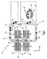
- FIG. 1 Fig. 3 is a plan view of a highly schematic system 10 for unmanned and fully automated picking according to the present invention.
- the system 10 may be constructed, for example, in a building (eg warehouse).
- the system 10 can be used as a storage and / or picking system.
- the system 10 here has a goods receipt area 12, a goods issue area or dispatch area 14, a storage area 16 and a first conveyor 18 in the form of a conveyor gyroscope 19.
- the first conveyor 18 may be realized in the form of eg roller conveyors, belt conveyors, chain conveyors, etc.
- the first conveyor 18 is over branch lines 20, which in the Fig. 1 are indicated in the form of double arrows, directly connected to the storage area 16.
- the conveyor technology sections 20, which function here as infeed and outfeed stitches can be of the same conveyor type as the first conveyor system 18.
- the gyro 19 can also be dissolved and replaced by individual conveyor connections between the individual system components.
- the conveyor system 18 could start, for example, in goods receipt 12 and end in goods issue 14, without goods receipt 12 and goods issue 14 being connected to each other via a conveyor system.
- the storage area 16 can, however, also be connected directly to the goods entrance 12 via a further conveyor 22, in order to be loaded with loading aids, such as e.g. Trays, containers, etc., not cumbersome and long to lead over the gyro 19, the gyro 19 itself can be directly connected via a further conveyor technology section 24 with the goods receipt 12.
- the gyro 19 may also be connected directly to the goods outlet 14, e.g. Storage containers can be sent from the storage area 16 directly to the shipping 14, without a picking (implementation of articles) is required. This may be the case, in particular, for large lots of a similar article type, e.g. entire pallets, containers or trays are ordered with articles of the same type.
- the goods receipt 12 and the goods issue can be directly connected to each other, as indicated by an arrow 28 with a dashed line.
- the gripping unit 30 engages articles that are either directly on the conveyor 18 or are stored in or on loading equipment, the loading equipment itself turn on the first conveyor technology.
- the gripping unit 30 is preferably mounted stationary on a building ceiling. Optionally, it is mounted above the first conveyor 18 on a frame (not shown).
- the gripping unit 30 grips articles and implements them.
- the articles are transferred to or dropped onto a second conveyor 32, eg, another conveyor.
- the second conveyor 32 couples to a plurality of job load aids, such as order containers 34, which may be cached in a job loader buffer 35.
- the buffer 35 is adjacent in the Fig. 1 directly to the second conveyor 32.
- the order loading aids 34 can in turn be transported into the dispatch area 14.
- Warehoused storage load aids are transported back to the storage area 16 or, if they are emptied, back into the goods receipt 12 after passing through the gripping unit 30.
- a unmanned, fully automated picking station is edged.
- the picking station 37 has at least the gripping unit 30.
- the picking station 37 may also have the first conveyor 18, the second conveyor 32 and the order load support buffer 35.
- the heart of the present invention is in the form of the gripping unit 30 in the Fig. 2 schematized shown in a perspective side view.
- the gripper unit 30 has a housing 40 in which a plurality of arms 42 are mounted. In the Fig. 2 For example, three arms 42 are shown.
- the arms 42 are constructed here by way of example in two parts, wherein the members are rotatably connected to each other by means of joints 44.
- the arms 42 are rotatably mounted in the housing 40.
- Opposite ends of the arms 42 are pivotally connected to a gripper 46, which in turn here by way of example two mechanical gripping tongs 48th having.
- Other gripper types, such as pneumatic suction devices, may also be used.
- a fourth arm 50 in the form of a rotary rod 50 is connected to the gripper 46.
- the rotary rod 50 is rotatable about its longitudinal axis, as indicated by a round double arrow.
- a fourth degree of freedom rotation about the Z-axis
- gripped articles are rotatable about a Z-axis.
- the number of degrees of movement could be increased by appropriate precautions. However, this would require additional mechanical elements which would limit the weight, and thus the speed with which the gripper 46 could be moved.
- the gripping unit 30 is able to move individual objects or articles, which can be arbitrarily selected from an article flow (loading aids or article heaps or groups), particularly quickly and precisely from one location to another location.
- An outstanding feature is the speed of the gripping unit 30, thanks to which the gripping unit 30 can provide up to 150 gripping and transfer cycles per minute. High web speeds and excellent positional accuracy are ensured. Appropriate control software enables the gripper unit 30 to follow high-speed conveyor techniques 18 with high accuracy.
- the housing 40 can be mounted either directly on a building ceiling or on a frame such that the first conveyor 18 (cf. Fig. 1 ) can be passed without problems under the gripping unit 30.
- the first conveyor 18 cf. Fig. 1
- the housing 40 can be mounted either directly on a building ceiling or on a frame such that the first conveyor 18 (cf. Fig. 1 ) can be passed without problems under the gripping unit 30.
- the first conveyor 18 cf. Fig. 1
- the gripping unit 30 has a radius of movement of preferably up to 1500 mm, with maximum accelerations of 10 g are possible.
- the greit unit 30 can lift articles of up to 2 kg.
- a control unit 31 may be integrated, which in the Fig. 3 is indicated by a rectangular box from a dashed line.
- the gripping unit 30 is preferably arranged centrally relative to a longitudinal axis of the first conveyor 18, in order to be able to access a maximum area on the first conveyor 18.
- the gripping unit 30 has a virtually circular working area 54.
- the working area 54 represents such positions in space that the gripper 46 (see FIG Fig. 2 ) can reach at maximum extended position of the arms 42.
- the overlapping region of the working area 54 with the first conveyor 18 represents a gripping area 56, which in the Fig. 3 also surrounded by a dashed line.
- the gripping area 56 is similar to a circle, which has been trimmed laterally by two circle segments.
- Fig. 3 Within the right circle segment there are in the Fig. 3 an overlapping area of the working area 54 with the second conveyor 32, which serves for the removal of converted articles 52, 52 ', 52 " Fig. 3 hatched drawn and is designated by the reference numeral 58. It represents a dispensing area 58. Within the dispensing area 58, a delivery point 60 is shown by means of a dashed line, the area of which substantially coincides with the area of an article 52 which is still on the first conveyor 18 within a receiving point 62 also indicated by a dashed line located. If in the following of dispensing or receiving points is spoken, so can so that a surface be meant.
- the article 52 may be, for example, a drug package.
- the gripping unit 30 grips the cuboid article 52 from the receiving point 52, while the first conveyor 18 moves continuously. Once the article 52 is gripped, the gripping unit 30 moves the article 52 out of the gripping area 56 into the storage area 58 and places the article 52 in the delivery point 60 on the second conveyor 32, which is oriented perpendicular to the first conveyor 18. Side of the second conveyor 32 are both left and right a plurality of order containers 34 are arranged, which are cached in buffers 35.
- the second conveyor 32 is realized here in the form of another belt conveyor, which is moved discretely or continuously in the direction of an arrow 64. Subsequently, it is assumed that the belt conveyor 32 is moved continuously in order to keep the throughput as high as possible.
- Each order container 34 is a discharge device 66, here exemplified in the form of a T-shaped slide assigned.
- a superordinated material flow computer or warehouse management computer 69 coordinates the discharge of the article 52 located on the second conveyor 32 into one of the order containers 34 by actuating an associated slider 66.
- the assignment of the article 52 to one of the order containers 34 has already been made in advance and deposited in the computer 69 , A conveyor technology for the removal of in the Fig. 3 Order container 34 shown on the right is not shown for reasons of clarity.
- a conveyor system 36 for delivery and removal of order containers 34 is in the left part of Fig. 3 indicated by a dashed line.
- order containers 34 can be transported into an order container buffer 35 ', which can optionally adjoin directly to the first conveyor 18 and which then lies in the working area 54 of the gripping unit 30.
- These order containers 34 are transferred between the buffer 35 'and the conveyor 36 by means of infeed / outfeed devices 68 (eg, belt ejectors, sliders, etc.).
- infeed / outfeed devices 68 eg, belt ejectors, sliders, etc.
- two order containers 34 of the buffer 35 ' are arranged within a further delivery area 58', which is likewise highlighted in hatched form. It is understood that with skillful placement or arrangement of the order container 34 of the buffer 35 ', more than two order containers 34 can be supplied simultaneously by the gripping unit 30 with articles 52, 52', 52 ".
- the left part of the Fig. 3 represents a modification opposite the right part of the Fig. 3
- the order containers 34 are placed directly in the working area 54 of the gripping unit 30.
- a sequencing stage (second conveyor 32) is eliminated. In order to shorten the time until an article is spent in its associated order container 34.
- the conveyor system 36 could also run directly adjacent parallel or obliquely to the first conveyor 18. In the case of a parallel arrangement can save the input / output devices 68, which in the Fig. 3 are illustrated in the form of double arrows. If the movement processes are suitably coordinated, the order containers 34 or the conveyor system 36 need not be stopped while the working area 54 or the delivery area 58 'of a gripping unit 30 is passed. The gripping unit 30 may deliver the articles directly into the order containers 34, of course assuming that they are so-called "dropable" articles. Fragile items should not be picked in this way. As regards the arrangement of the individual components (conveying techniques 18, 32) in the vertical direction, will be discussed in more detail below.
- the second conveyor 32 is to be arranged almost at the same level as the first conveyor 58.
- the order load conveyor conveyor 36 is disposed at such a level relative to the first conveyor 18 that an upper edge of an order container 34 in the buffer 35 'is at the same height as or below the first conveyor 18.
- Such a vertical arrangement is recommended because the lifting unit 30 in its usual embodiment has only a relatively small stroke, but achieved very high speeds in the horizontal direction of movement.
- the gripping unit 30 and the gripper 46 (see Fig. 2 ), which may also be in the form of a pneumatic nipple, can be accelerated with up to 10 g.
- an additional vertical lifting unit is mounted at the lower end of the arms 42 in the region of the gripper 46 in order to be able to generate an additional stroke.
- the gripper 46 is then preferably in the form of a pneumatic nipple.
- Fig. 4 is a plan view of another embodiment of a picking system 10 'according to the present invention shown.
- two gripping units 30 are arranged serially one behind the other to unload load carriers 70, 72 or to grasp articles directly on the first conveyor 58, as shown at 74, and to translate them to second conveyor techniques 32.
- the storage load supports 70, 72 and an article accumulation 74 are transported on the first conveyor 18 counterclockwise from the goods receipt 12 or the warehouse 16 to the gripping units 30, as shown by an arrow 53.
- an image recognition unit 38 is preferably arranged in each case.
- the image recognition unit 38 can be designed in the form of a camera system that is arranged above the first conveyor 18 and looks down onto the conveyor 18.
- illuminants can be provided below a conveying means (e.g., belt) of the first conveyor, it being then advisable to make the conveying means of the first conveyor 18 translucent.
- the resolution or the contrast can be increased such that an object recognition software itself chaotically arranged articles, such as. may be present in the accumulation 74, with respect to their position and orientation relative to the first conveyor 18 can determine.
- Corresponding software packages are commercially available. The same applies to the camera system.
- Each of the two gripping units 30 of Fig. 4 preferably supplies two secondary conveyor techniques 32 with articles arranged perpendicular to the first conveyor 18.
- Each side of the second conveyor techniques 32 a buffer 35 for one or a plurality of order loading aids, here order container 34, is provided. Conveying techniques with which the order container 34 are transported into the buffer 35 and are transported from the buffers 35 to a goods outlet, not shown here, are not shown for reasons of clarity.
- the discharge devices 66 which are shown by way of example only in the left, second conveyor 32 of the upper fully automated and unmanned picking with the first gripping unit 30.
- the second conveyor techniques 32 are arranged here at the same height as the first conveyor 18. With the in the Fig. 4 As shown, up to forty picking orders can be processed in parallel since each of the buffers 35 has five target locations at which the order containers 34 can be positioned.
- the order loading means 34 could also be transported parallel to the first conveyor 18 in the area of the gripping units 30, preferably at the same speed as the articles on the first conveyor 18. In this case, picking orders could be processed serially by the two gripping units 30.
- the in the Fig. 4 The gripping unit 30 shown above could, in a first cycle, feed all articles from the first conveyor 18 into an order loader 34 which would then be positioned relative to the first conveyor 18 such that the upper edge of the order loader 34 is either at the same height as a top of the first conveyor 18 or less. All articles which the first upper gripping unit 30 fails to create because the articles leave the gripping area can subsequently be transferred from the second gripping unit 30 into the parallel-carried order loading aid 34.
- the bearing 16 is in the Fig. 4 partially cut open.
- a rack aisle 75 is shown, in which a storage and retrieval unit 76 can move along the rack aisle and vertically on the front of the shelf.
- the storage and retrieval unit 76 may have two load handling devices in order to be able to transport two loading aids (container and / or tray) at the same time.
- containers 70 are stored in the upper shelf.
- shelves 72 are stored in the lower shelf.
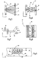
- FIG. 5 a plan view of isolated parts of a further modification is shown.
- the Fig. 5 shows a gripping unit 30 which is disposed above a first conveyor 18 and which can provide a plurality of webs 78 with articles.
- the left ends of the conveyor tracks 78 all end in the working area of the gripping unit 30.
- the opposite ends of the conveyor track 78 terminate at destination points 81, which are arranged here by a conveyor 36 for order containers 34. It is possible that at each of the gripping unit 30 opposite end of the conveyor tracks 78, an order container 34 is positioned at a target point 81, one of which in the Fig. 5 indicated by a dashed line.
- the conveyor tracks 78 may be e.g. to act driven roller conveyors or straps.
- gravity tracks may be used, e.g. in the form of, with respect to a horizontal, slanted slide plate or in the form of, with respect to a horizontal, inclined Losrollenbahn can be formed.
- FIG. 6 a further modification is shown in a plan view.
- a gripping unit 30 is arranged above a first conveyor 18.
- Side of the first conveyor 18 a plurality of accumulation conveyors 80, here a total of five accumulation conveyor 80, coupled to the first conveyor 18.
- the opposite ends of the accumulation conveyor 80 also couple to a conveyor 36 for order containers 34th
- the length of the accumulation conveyor is arbitrary. If the accumulation conveyor 80 are sufficiently long, in each case a liftable and lowerable stop 82 can be provided in the middle thereof, as in Fig. 6 is indicated by a dashed line to divide the accumulation conveyor into several sections or tracks.
- Fig. 6 five parallel adjacent accumulation conveyor are shown, which are divided by the stop 82 in a total of ten storage sections. These ten jam sections are shown in circles with the passing numbers from 0 to 9.
- Articles that are delivered via the first conveyor 18 to the gripping unit 30 can be transferred depending on order picking in one of the five accumulation conveyor 50. It is understood that the accumulation conveyor 80 all have an end which lies in the working area of the gripping unit 30.
- the corresponding stop member 82 of this accumulation conveyor 80 can be raised so as to provide the second jam section for another order picking.
- Ready picked orders can then be accessed and picked up by passing order containers 34.
- FIG. 7 a side view of another embodiment is shown.
- a gripping unit 30 which in turn is arranged above a first conveyor 18, here three secondary conveyor techniques 32-1, 32-2 and 32-3 are arranged vertically one above the other.
- a conveyor 36 for order container 34 is arranged at its gripping unit 30.
- the three conveyor techniques 32-1 to 32-3 are arranged such that arise in the delivery area of the gripping unit 30 vertical dispensing windows, which in the Fig. 7 are indicated by vertical dashed lines.
- the gripper unit 30 To provide articles to the upper conveyor 32-1, the gripper unit 30 must be moved furthest in the X direction. In order to supply articles to the lowermost conveyor system 32-3, the gripping unit 30 has to travel the shortest path in the X direction.
- the middle conveyor 32-3 requires movement of the gripper unit 30 in a central area in the X direction.
- the conveyor techniques 32-1 to 32-3 are driven here to load the articles in the Fig. 7 from left to right in the direction of the order container 34 to move. It It goes without saying that gravity railways can also be used here in order to be able to dispense with a drive.
- the secondary conveyor techniques 32 may further be arranged in the horizontal at an angle to each other, as in the Fig. 5 already shown for the gravity conveyor 78.
- the second conveyor techniques 32 of Fig. 7 Alternatively, they can be arranged in parallel next to each other in larger numbers, as in Fig. 6 is shown.
- a tray 72 is shown as being used to present the full range of articles to the gripper unit 30 in one hour, as discussed above.
- the tray 72 has a circumferential border 90. In the interior of the tray 72 can be provided in the longitudinal direction compartment partitions 92, for example, to define four tablet rows.
- the left tray series is fully stocked with articles 52.
- the subsequent tray series 94 has only one article 52 '.
- the second tray row from the right is itself subdivided into a plurality of tray individual compartments 98 with the aid of further compartment subdivisions 96. Some of these single shelves 98 are equipped with articles 52 " Fig. 8 tray series 94 'shown on the right is empty.
- Fig. 9 will be explained how to use without image recognition unit 38 (in contrast to the Fig. 1 and 4 ) can nevertheless safely and reliably grasp articles from the first conveyor 18 by means of the gripping unit 30.
- imaginary windows 100 are defined on the first conveyor 18 in the control unit.
- the imaginary windows 100 are formed by imaginary fields 102, which in turn are bounded by imaginary halftone dots 104 in their corners.
- the articles 52 are preferably applied individually to appropriately designed article trays 106, 108 set.
- the base area of the article trays 106, 108 preferably corresponds substantially to the base area of the different article types 52, 52 '.
- a cuboid 52 and two cubes 52 ' are each provided on a separate tray 106 and 108, respectively.
- the trays 106, 108 are aligned at the grid points 104 and placed on the grids 102.
- This process takes place, for example, in the area of the goods receipt 12 and / or of the warehouse 16.
- Loading devices provided for this purpose are controlled by the higher-level control unit 69 in such a way that the trays 106, 108 are placed on the grids provided for this purpose.
- the gripping unit 30 thus has absolute position data of the articles 52, 52 'relative to the first conveyor 18. Since the articles 52, 52' are each on a separate loading means 106, 108, it is for the gripper 46, in this case in shape is formed by mechanical pliers, irrelevant which type of article is actually stored on the loading aid 106, 108. A separation of the articles 52, 52 'from the loading equipment 106, 108 takes place at a later date.
- FIG. 10 a flowchart of a method is shown.
- a gripping unit 30 is provided in a first step S1.
- an article stream is conveyed to the gripping unit 30 via the first conveyor 18.
- the gripping unit 30 picks individual predetermined articles from the stream and places them in the delivery area, the gripping unit operating at a rate of up to 1500 items per hour or even up to 4000 items per hour.
- Returned goods are item shipments that are returned by the customer and then have to be returned to the warehouse. Returns consignments are characterized by the fact that many different items are usually contained in small numbers.
- the items of the return shipment can be given to the first conveyor and promoted as a group to a gripping unit.
- An image recognition unit located downstream of the gripping unit captures an image. With appropriate contour resolution algorithms, the positions and orientations of the individual articles can be resolved. This in turn generates control data for the gripping unit, which makes it possible to grasp the articles safely and reliably, even during a continuous conveying operation of the first conveyor system.
- scrapers can be used to break up the stacks and thus produce a single layer of articles.
- a scraper brush-like devices can be used, which are arranged horizontally at sometimes different heights across the first conveyor. It is understood that such stack-dissolving devices can of course also be used when picking normal items, especially when the gripping unit engages directly from the first conveyor, and thus not from loading equipment.
- these articles can be passed to specific article identification devices to be identified in terms of article type. Identified items can be cached until the parent machine has fetched the correct storage bin to then place the cached item into a bin associated with its item type.
Description
Die vorliegende Erfindung betrifft ein System zum vollautomatisierten, mannlosen Kommissionieren von Artikeln, die vorzugsweise in Lagerladehilfsmitteln bevorratet sind, hinein in Auftragsladehilfsmittel, und zwar gemäß einem Kommissionierauftrag.The present invention relates to a system for the fully automated, unmanned picking of articles, which are preferably stored in storage loading equipment, in order loading equipment, according to a picking order.
In der heutigen Zeit gibt es im Wesentlichen zwei Kommissionierstrategien, die durch eine technisch-organisatorische Ausstattung bedingt sind. Bei der ersten Strategie wird nach dem "Mann-zur-Ware"-Prinzip gearbeitet. Bei der zweiten Strategie wird nach dem "Ware-zum-Mann"-Prinzip gearbeitet. Je nach Strategie wird eine zeitlich-räumliche Abarbeitung von Kommissionieraufträgen festgelegt. Ein Kommissionierauftrag umfasst mehrere Positionen (Zeilen) mit verschiedenen Artikeln in unterschiedlichen Anzahlen.At the present time, there are essentially two picking strategies, which are conditioned by a technical-organizational equipment. The first strategy is based on the "man-to-goods" principle. The second strategy is based on the "goods-to-man" principle. Depending on the strategy, a temporal-spatial processing of picking orders is defined. A picking order comprises several items (lines) with different items in different numbers.
Bei einem großen Artikelsortiment, das eine Vielzahl von verschiedenen Artikeltypen umfasst, wird üblicherweise nach dem "Ware-zum-Mann"-Prinzip. Dabei werden z.B. Lagerbehälter aus einem Behälterlager zu einem Kommissionierplatz gefördert, wo eine Kommissionierperson die Artikel händisch aus den Lagerbehältern entnimmt und sie in Auftragsbehälter gibt, die im Bereich des Kommissionierplatzes angeordnet sind. Ein Materialfluss- bzw. Lagerverwaltungsrechner weist den Auftragsbehältern jeweils einen Kommissionierauftrag zu und sorgt dafür, dass die richtigen Lagerbehälter, die die für den jeweiligen Kommissionierauftrag benötigten Artikel enthalten, zu dem Kommissionierplatz gefördert werden, wo der dazu gehörige Auftragsbehälter abgearbeitet wird.With a large assortment of articles comprising a multitude of different types of articles, it is customary to follow the "goods-to-man" principle. In doing so, e.g. Storage containers conveyed from a container storage to a picking station, where a picking person removes the items manually from the storage containers and they are in order container, which are arranged in the picking area. A material flow or warehouse management computer assigns a picking order to the order containers and ensures that the correct storage containers containing the articles required for the respective picking order are conveyed to the order picking station where the associated order container is processed.
Wenn das Artikelsortiment nicht allzu groß ist und wenn die zu kommissionierenden Artikel gut stapelbar und in hohen Anzahlen abgerufen werden, werden üblicherweise sogenannte A-Frames bzw. Kommissionierautomaten eingesetzt. Ein exemplarischer A-Frame ist in dem Dokument
Mit den oben erwähnten herkömmlichen Kommissionierplätzen lassen sich Kommissionierleistungen in der Größenordnung von bis zu 1000 Artikel pro Stunde realisieren. Die Kommissionierperson stellt dabei einen Flaschenhals dar, da sie manuell arbeitet und somit die maximale Anzahl von Zugriffen auf ca. 1000 pro Stunde begrenzt.With the above-mentioned conventional picking stations, order picking performances on the order of up to 1000 articles per hour can be realized. The picking person represents a bottleneck because it works manually and therefore limits the maximum number of accesses to about 1000 per hour.
Trotz - im Vergleich zu Kommissionierautomaten - relativ geringen Kommissionierleistungen müssen herkömmliche Kommissionierplätze eingesetzt werden, da nicht jeder Artikel in einem Automatenschacht bevorratet werden kann. Insbesondere runde Artikel, wie z.B. Flaschen und Ähnliches, sind mit Kommissionierautomaten schwer handhabbar. Gleiches gilt für Artikel mit größeren Abmessungen, von denen dann nur eine geringe Anzahl pro Kommissionierschacht in einem Kommissionierautomaten bevorratet werden kann.Despite - compared to picking machines - relatively low order picking conventional picking must be used because not every item can be stored in a vending machine shaft. In particular, round articles, such as e.g. Bottles and the like, are difficult to handle with order picking machines. The same applies to articles with larger dimensions, of which then only a small number per picking shaft can be stored in a picking machine.
Obwohl der Kommissionierautomat ein vollautomatisiertes und mannlos funktionierendes System darstellt, besteht ein Bedürfnis nach einer weitergehenden Automatisierung, insbesondere im Bereich von Artikeln, welche mit einem Kommissionierautomaten nicht handhabbar sind.Although the picking machine is a fully automated and unmanned system, there is a need for further automation, especially in the field of articles that are not manageable with a picking machine.
Des Weiteren sind Entladeroboter und Beladeroboter bekannt, um insbesondere Paletten mit Artikeln zu bestücken bzw. Artikel von den Paletten zu nehmen. Im Dokument
Abgesehen von dem relativ großen Platz- und Raumbedarf derartiger Roboter sind diese schon aufgrund ihrer geringen Leistung (Greif- und Umsetzvorgänge/Stunde) für den Einsatz in Kommissionieranlagen, insbesondere für den Vorgang des Transferierens von Artikeln aus Lagerladehilfsmitteln in Auftragsladehilfsmittel nicht geeignet. Ein Greifen von kleineren Artikeleinheiten, wie z.B. Schachteln, vermögen diese Roboter nicht zu leisten. Bisherige konventionelle Roboterlösungen sind im Wesentlichen auf die Handhabung von sogenannter Bulk-Ware bzw. Artikel in Kartons oder Umverpackungen (typischerweise vier oder mehr Artikel pro Einheit) beschränkt.Apart from the relatively large space and space requirements of such robots, these are already due to their low performance (gripping and transfer operations / hour) for use in order picking, especially for the process of transferring articles from storage loading equipment in job loader not suitable. A gripping of smaller article units, such as e.g. Nesting, these robots can not afford. Previous conventional robot solutions are essentially limited to the handling of so-called bulk goods or articles in cartons or outer packaging (typically four or more articles per unit).
Verpackungsroboter bzw. Palettierroboter, wie sie oben erwähnt sind, werden in den Dokumenten
Die
Es ist daher eine Aufgabe der vorliegenden Erfindung, eine Vorrichtung zum mannlosen, vollautomatisierten Kommissionieren von Artikeln gemäß Kommissionieraufträgen bereitzustellen, wobei Kommissionierleistungen möglich sein sollen, die signifikant über der Marke von 1000 Zugriffen pro Stunde liegen. Die zu kommissionierenden Artikel sollen auch Artikel enthalten, die mit einem Kommissionierautomaten gar nicht oder nur schlecht handhabbar sind. Dabei soll insbesondere nach dem Prinzip "Ware zum Mann" gearbeitet werden, um Artikel, die in Lagerladehilfsmitteln bevorratet sind, in Auftragsladehilfsmittel umzusetzen.It is therefore an object of the present invention to provide a device for the unmanned, fully automated picking of articles according to picking orders, whereby picking services are to be possible, which are significantly above the mark of 1000 accesses per hour. The articles to be picked should also contain articles that are not or only poorly manageable with a picking machine. In particular, the principle of "goods to man" should be used in order to implement articles stored in storage load equipment in order loading equipment.
Diese Aufgabe wird mit einem Lager- und Kommissioniersystem gemäß dem Anspruch 1This object is achieved with a storage and picking system according to claim 1
Anstatt einer händischen Kommissionierung erfolgt die Kommissionierung nun vollautomatisch mit einer Robotergreifeinheit. Der Roboter übernimmt die Aufgabe des Kommissionierers voll. Er greift die Artikel, was ursprünglich einer der Hauptgründe war, warum man überhaupt Menschen beim Auftragskommissionieren eingesetzt hat, und setzt gegriffene Artikel mit einer wesentlich höheren Geschwindigkeit und Präzision um. Menschen werden in einem erfindungsgemäßen System - zumindest zum Kommissionieren - nicht mehr benötigt. Der Roboter kann ohne Probleme 1500 Artikel pro Stunde von einem Förderband greifen und z.B. auf ein zweites Förderband absetzen, das seitlich zum zweiten Förderband angeordnete Auftragsbehälter mit den gemäß den Kommissionieraufträgen vorbestellten Artikeln versorgt und somit als Sorter dient. Mit einer Kommissionierleistung von sogar bis zu 4000 Stück pro Stunden liegt man also genau im Sektor zwischen der herkömmlichen manuellen Kommissionierung (1.000 Stück pro Stunde) und der klassischen Automatenkommissionierung (10.000 Stück pro Stunde und mehr). Der Roboter macht auch keine Fehler beim Greifen. Die Artikel werden vorzugsweise einzeln umgesetzt, was aufgrund der hohen Geschwindigkeit problemlos möglich ist, so dass immer die richtige Anzahl von Artikeln eines Typs umgesetzt werden, was beim mamuellen Kommissionieren nicht immer der Fall ist.Instead of a manual picking, the picking is now fully automatic with a robotic gripping unit. The robot takes over the task of the order picker fully. He picks up the articles, which was originally one of the main reasons why people have ever been used in order picking, and handles used articles with a much higher speed and precision. People are in a system according to the invention - at least for picking - no longer needed. The robot can easily grab 1500 articles per hour from a conveyor belt and settle on a second conveyor belt, for example, which supplies the order containers arranged laterally to the second conveyor belt with the articles pre-ordered according to the picking orders and thus serves as a sorter. With a picking capacity of even up to 4000 pieces per hour, you are exactly in the sector between the conventional ones manual order picking (1,000 pieces per hour) and classic automatic picking (10,000 pieces per hour and more). The robot also makes no mistakes when gripping. The articles are preferably implemented individually, which is easily possible due to the high speed, so that always the right number of articles of a type are implemented, which is not always the case with manual picking.
Die Anschaffungskosten für einen derartigen Greif- und Umsetzroboter amortisieren sich üblicherweise innerhalb von zwölf bis achtzehn Monaten, und zwar trotz relativ hoher Anschaffungskosten. In diesem Zusammenhang ist zu beachten, dass beim erfindungsgemäßen System kein Personal benötigt wird, so dass man sich über längere Zeit gesehen die Personalkosten vollständig einspart.The initial cost of such a robotic and Umsetzroboter usually pay for itself within twelve to eighteen months, and despite relatively high initial cost. In this context, it should be noted that no staff is needed in the system according to the invention, so that you can save the staff costs completely over a longer period of time.
Ferner ist die Kommissionierfehlerrate auch deshalb bedeutend geringer, weil ein Roboter niemals müde wird, so dass sich der bei Menschen mit zunehmender Arbeitszeit negativ bemerkbar machende Konzentrationsabfall vorliegend nicht ergibt. Mit dem erfindungsgemäßen System kann man an sieben Tagen jeweils vierundzwanzig Stunden arbeiten.Furthermore, the Kommissionierfehlerrate is also significantly lower because a robot never gets tired, so that there is no present in humans with increasing working time negatively affecting concentration drop. With the system according to the invention, it is possible to work for twenty-four hours every seven days.
Das system weist ferner eine Bilderkennungseinheit zum Erfassen und Auswerten einer Position bzw. eines Orts und einer Orientierung eines jeden Artikels in dem Strom auf der ersten Fördertechnik auf, wobei die Bilderkennungseinheit stromaufwärts relativ zur Greifeinheit angeordnet ist und selbst chaotisch orientierte Artikel innerhalb des Stroms auflösen, und insbesondere identifizieren, kann.The system further comprises an image recognition unit for detecting and evaluating a location and an orientation of each article in the stream on the first conveyor, the image recognition unit being located upstream relative to the gripper and even disintegrating chaotically oriented articles within the stream; and in particular, can identify.
Die Bilderkennungseinheit kann ein Kamerasystem sein, mit dem Bilder der Artikelverteilung auf der ersten Fördertechnik aufgenommen werden. Dabei ist es irrelevant, ob die Artikel direkt auf der Fördertechnik oder in Ladehilfsmittel gefördert werden. Die erfindungsgemäß eingesetzte Bildverarbeitungssoftware ist in der Lage selbst Artikel in einer oberen Schicht eines Artikelhaufens bzw. -stapels derart aufzulösen, dass ein jeweiliger Ort (Position) und eine jeweilige Orientierung bekannt sind, um der Greifeinheit entsprechende Positionsdaten (relativ zur Fördertechnik) zum Greifen der Artikel übermitteln zu können. Die Bildverarbeitung vereinfacht sich entsprechend, wenn die Artikel einigermaßen geordnet vorliegen, wie z.B. in einem Behälter oder auf einem Tablar mit Fachunterteilung. Die Bilderkennungseinheit muss dann lediglich den Ort solcher Artikel bestimmen, die tatsächlich vorhanden sind.The image recognition unit may be a camera system with which images of the article distribution on the first conveyor technology are recorded. It is irrelevant whether the items are conveyed directly on the conveyor or in loading equipment. The image processing software used according to the invention is capable of dissolving even articles in an upper layer of an article heap or stack in such a way that a respective location (position) and a respective orientation are known in order to be able to transmit position data corresponding to the gripping unit (relative to the conveyor technology) for gripping the articles. The image processing is simplified accordingly, if the articles are reasonably arranged, such as in a container or on a shelf with compartment division. The image recognition unit then only needs to determine the location of such articles that are actually present.
Weiter ist es bevorzugt, wenn jeder Artikel auf einem eigenen Artikelladehilfsmittel an einer jeweils fest vorgegebenen Position auf der ersten Förderstrecke in den Greifbereich hineingefördert und dort samt dem Artikelladehilfsmittel gegriffen und umgesetzt wird.Further, it is preferred if each article is conveyed on its own article loading aid at a respectively predetermined position on the first conveyor line in the gripping area and gripped there together with the article loading aid and implemented.
Wenn jeder Artikel auf einem separaten Artikelladehilfsmittel, wie z.B. einem Tablar, bereitgestellt wird, kann die Greifvorrichtung ohne Bilderkennung auskommen. Dazu ist es erforderlich, dass diese Tablare an vorbestimmten (Raster-)Punkten relativ zur ersten Förderstrecke, wie z.B. einem Gurtband, ausgerichtet werden, bevor sie in den Arbeits- bzw. Greifbereich der Greifeinheit kommen. Eine übergeordnete Steuereinrichtung, wie z.B. ein Materialflussrechner oder ein Lagerverwaltungsrechner, hat dann Kenntnis darüber, welcher Artikel auf welcher Position des Förderbands angeordnet ist. Aufgrund der Kenntnis der Fördergeschwindigkeit lassen sich somit die Position und Orientierung der zu kommissionierenden Artikel vorhersagen und in Form von Positionssteuerdaten an die Greifeinheit vorab übermitteln. Des Weiteren können die geometrischen Abmessungen der Artikel im System hinterlegt sein, um der Greifeinheit bereits vorab die richtigen Anfahrpositionen (von oben, von links, von rechts, etc) zum Initiieren eines Greifvorganges zu übermitteln.When each article is printed on a separate article loading tool, such as a tray is provided, the gripping device can do without image recognition. For this purpose, it is necessary that these trays are at predetermined (raster) points relative to the first conveyor line, such as e.g. a webbing, before they come into the working or gripping area of the gripping unit. A superordinate control device, such as e.g. a material flow computer or a warehouse management computer, then has knowledge of which article is arranged on which position of the conveyor belt. Due to the knowledge of the conveying speed, the position and orientation of the articles to be picked can thus be predicted and transmitted in advance in the form of position control data to the gripping unit. Furthermore, the geometrical dimensions of the articles can be stored in the system in order to transmit to the gripping unit already in advance the correct starting positions (from above, from left, from right, etc.) for initiating a gripping process.
Trotz der hervorragenden Zuverlässigkeit heutiger Bildverarbeitungsprogramme stellt diese Lösung einen gangbaren Weg dar, wenn man ohne Bilderkennungseinheit auskommen möchte. Dieser Aspekt spielt insbesondere bei der Nachrüstung bzw. Umrüstung von bereits bestehenden Kommissionieranlagen eine Rolle. Die Übermittlung von Steuerdaten für einen Roboter ist mit gängigen Systemen zwar problemlos möglich. Die Berechnung von Anfahrpositionen kann jedoch, insbesondere für alte Systeme, eine größere rechentechnische Herausforderung darstellen, so dass einige Betreiber von Kommissionieranlagen möglicherweise auf eine Bildverarbeitung verzichten wollen. Dies ist auf die oben beschriebene Art möglich.Despite the excellent reliability of today's image processing programs, this solution is a viable option if you want to get along without an image recognition unit. This aspect plays a role especially in the retrofitting or conversion of already existing order picking. The transmission of control data for a robot is without problems with common systems possible. The calculation of approach positions, however, can be a major computational challenge, especially for old systems, so that some operators of picking systems may want to do without image processing. This is possible in the manner described above.
Gemäß einer weiteren bevorzugten Ausführungsform kann die Greifeinheit Artikel mit einem jeweiligen Gesamtgewicht von bis zu 2 kg mit Beschleunigungen von bis zu 150 m/s2 umsetzen. Der Arbeitsbereich hat vorzugsweise einen Durchmesser von 1500 mm, und zwar bei einem Hub von vorzugsweise 60 mm.According to a further preferred embodiment, the gripping unit can implement articles with a respective total weight of up to 2 kg with accelerations of up to 150 m / s 2 . The working area preferably has a diameter of 1500 mm, with a stroke of preferably 60 mm.
Ohne Last kann der Greifroboter, wie er bei der vorliegenden Erfindung eingesetzt wird, Beschleunigungen von bis zu 10 g bewirken. Diese Eigenschaften ermöglichen die enorme Geschwindigkeit beim Umsetzen und somit die Erhöhung der Kommissionierleistung auf eine Größenordnung von sogar bis zu 4000 Artikel pro Stunde.Without load, the gripper robot, as used in the present invention, can cause accelerations of up to 10 g. These features allow for tremendous speed in the process of transfer, increasing order picking to as much as 4,000 items per hour.
Erfindungsgemäß ist zumindest eine zweite Fördertechnik vorgesehen, die im Arbeitsbereich der Greifeinheit schräg, vorzugsweise senkrecht an die erste Fördertechnik koppelt und die mit dem Auftragsladehilfsmittelpuffer, insbesondere mit den Zielstellen, verbunden ist.According to the invention, at least one second conveyor system is provided, which in the working area of the gripper unit connects obliquely, preferably vertically, to the first conveyor system and which is connected to the order loading aid buffer, in particular to the destination locations.
Die zweite Fördertechnik dient dann als Sorter und versorgt eine Vielzahl von Zielstellen bzw. Auftragsladehilfsmitteln, wie z.B. Auftragsbehälter, mit zu kommissionierenden Artikeln. Dies ist besonders von Vorteil, wenn mehrere Greifroboter seriell hintereinander relativ zur ersten Förderstrecke angeordnet sind. Der ersten Greifroboter kann dann solche Artikel aus dem Artikelstrom greifen, die mit unter chaotisch im Artikelstrom angeordnet sind, ohne alle anderen Artikel des Stroms, die nicht Zielstellen der dieser Greifeinheit zugeordneten zweiten Förderstrecke zugewiesen sind, ebenfalls von der ersten Förderstrecke heruntergefördert werden, wie es beispielsweise beim herkömmlichen Einsatz von Linearschiebem, Drehschiebern, Anschlägen, etc. der Fall war. Ein gezielter Zugriff auf beliebig auswählbare Artikel im Artikelstrom auf der ersten Fördertechnik ist mit einer überragenden Geschwindigkeit möglich.The second conveyor then serves as a sorter and provides a variety of destinations or job loading equipment, such as order container, with articles to be picked. This is particularly advantageous if a plurality of gripper robots are arranged serially one behind the other relative to the first conveyor track. The first gripping robot can then grasp such articles from the stream of articles, which are arranged under chaotic in the article flow, without all other articles of the stream, which are not assigned to target points of this gripper unit associated second conveyor line, are also promoted from the first conveyor line, as it For example, in the conventional use of Linearschiebem, rotary valves, attacks, etc. was the case. A targeted access to arbitrary selectable articles in the Article flow on the first conveyor is possible at an outstanding speed.
Gemäß einer weiteren bevorzugten Ausführungsform umfasst die zweite Fördertechnik eine Vielzahl von angetriebenen Stauförderern und/oder Schwerkraftbahnen, von denen jeder bzw. jede in einer Zielstelle enden kann. Der Einsatz von Stauförderern bzw. -bahnen hat sich als besonders vorteilhaft herausgestellt, da dann der Verkehr der Auftragsladehilfsmittel besser fließt, insbesondere wenn die Auftragsladehilfsmittel während ihrer Befüllung auf einer Auftragsladehilfsmittel-Förderstrecke verbleiben, d.h. nicht in einen Puffer ausgeschleust werden. Mit Hilfe der Stauförderer können alle Artikel eines Auftrags gesammelt werden, bevor sie in ein Auftragsladehilfsmittel abgegeben werden. Während die Artikel gesammelt werden, können die Auftragsladehilfsmittel auf der Auftragsladehilfsmittel-Fördertechnik frei an den Staubahnen vorbeitransportiert werden. Nur im Falle einer Übergabe eines gesammelten, und somit abgeschlossenen, Kommissionierauftrags wird der Ladehilfsmittelfluss auf der Auftragsladehilfsmittel-Fördertechnik angehalten. Dies erhöht den Durchsatz an Auftragsladehilfsmitteln im Gesamtsystem.According to a further preferred embodiment, the second conveyor technique comprises a plurality of driven accumulation conveyors and / or gravity tracks, each of which may terminate in a target location. The use of accumulation conveyors or webs has been found to be particularly advantageous, since then the traffic of the order loading aid flows better, especially if the order loading aids remain during their filling on a job load support conveyor line, i. not be dumped into a buffer. With the help of the accumulation conveyors all articles of an order can be collected, before they are put into a job loader. As the articles are being collected, the order loader aids on the order load conveyor conveyance can be transported freely past the dust tracks. Only in the case of a transfer of a collected, and thus completed, picking order, the loading aid flow is stopped on the order loading equipment conveyor. This increases the throughput of job load aids in the overall system.
Bei einer besonderen Ausgestaltung der Erfindung ist die zweite Fördertechnik mit der ersten Fördertechnik auf einer Höhe und/oder darunter angeordnet.In a particular embodiment of the invention, the second conveyor with the first conveyor technology is arranged at a height and / or below.
Da die Greifeinrichtung vorzugsweise nur einen begrenzten Hub hat, ist es von Vorteil, wenn die zweite Fördertechnik annähernd auf der gleichen Höhe wie die erste Fördertechnik angeordnet ist. Bei einer Anordnung, bei der die zweite Fördertechnik unterhalb der ersten Fördertechnik angeordnet ist, können Artikel, die von der Greifeinrichtung gegriffen sind, oberhalb der zweiten Fördertechnik abgeworfen werden. Auf diese Weise ist es möglich, dass man mehrere zweite Fördertechnikstrecken übereinander anordnet, und zwar jeweils mit einem leichten horizontalen Versatz, so dass jede zweite Fördertechnikstrecke ein zugeordnetes Abwurffenster aufweist, damit Artikel auf sie abgeworfen werden können. Dies gilt natürlich nur unter der Voraussetzung, dass die Artikel beim Abwerfen nicht zerbrechen. Schwerkraftbahnen haben den Vorteil, dass für eine Bewegung der auf der Schwerkraftbahn befindlichen Artikel kein Antrieb erforderlich ist. Die Schwerkraftbahnen können beispielsweise in Form von relativ glatten Blechen (Rutschen), Losrollenbahnen, etc. implementiert sein, die von der ersten Fördertechnik hin zu den Auftragsladehilfsmitteln abfallend geneigt sind.Since the gripping device preferably has only a limited stroke, it is advantageous if the second conveyor is arranged approximately at the same height as the first conveyor. In an arrangement in which the second conveyor is arranged below the first conveyor, articles gripped by the gripper may be dropped above the second conveyor. In this way, it is possible that one arranges several second conveyor lines one above the other, each with a slight horizontal offset, so that every second conveyor track has an associated ejection window, so that articles can be dropped onto them. Of course, this only applies on condition that the items do not break when dropped. Gravity trains have the advantage that no drive is required for a movement of the items located on the gravity track. The gravity tracks may be implemented, for example, in the form of relatively smooth sheets (chutes), idler tracks, etc. that are sloped sloping from the first conveyor to the job load tools.
Außerdem hat es sich als vorteilhaft herausgestellt, wenn die Steuereinheit eine Fördergeschwindigkeit der ersten Fördertechnik in Abhängigkeit von einer Artikeldichte auf der ersten Fördertechnik regelt.In addition, it has proven to be advantageous if the control unit regulates a conveying speed of the first conveyor system as a function of an article density on the first conveyor system.
Wenn die Artikeldichte auf der ersten Fördertechnik sehr hoch ist, kann es aus mehreren Gründen von Vorteil sein, wenn man die Fördergeschwindigkeit erniedrigt. Zum einen erleichtert dies im Falle einer computergestützten Bilderkennung (Artikelidentifizierung umfassend Positions- und Orientierungsbestimmung) die Auflösung einzelner Artikel auf der ersten Fördertechnik. Befinden sich sehr viele Artikel auf der ersten Fördertechnik, kann die Verringerung sogar zwingend erforderlich sein, um der Bilderkennungseinheit ausreichend Zeit zu geben, um die für eine Identifizierung erforderliche Rechenzeit zur Verfügung zu stellen. Befinden sich hingegen nur wenig Artikel auf der ersten Fördertechnik, d.h., wenn die Artikeldichte gering ist, kann die erste Fördertechnik ggf. mit einer höheren Fördergeschwindigkeit betrieben werden. Die Greifeinheit ist üblicherweise in der Lage, selbst einem Artikel mit höherer Geschwindigkeit auf der ersten Fördertechnik während des Greifvorgangs zu folgen.If the article density on the first conveyor is very high, it can be advantageous for several reasons to lower the conveyor speed. On the one hand, in the case of computer-aided image recognition (article identification comprising position and orientation determination), this facilitates the resolution of individual articles on the first conveyor. If there are a great many articles on the first conveyor, the reduction may even be necessary in order to give the image recognition unit sufficient time to provide the computing time required for an identification. If, on the other hand, there are only a few articles on the first conveyor system, that is, if the article density is low, the first conveyor system can possibly be operated at a higher conveyor speed. The gripping unit is usually able to follow even a higher speed article on the first conveyor during the gripping process.
Gemäß einer weiteren bevorzugten Ausführungsform ist ferner eine Auftragsladehilfsmittel-Fördertechnik vorgesehen, die im Arbeitsbereich der Greifeinheit unter der ersten Fördertechnik hindurchgeführt ist und/oder die Zielstellen mit einem Versandbereich verbindet.According to a further preferred embodiment, an order loading aid conveyor system is further provided, which is guided in the working area of the gripping unit under the first conveyor and / or connects the destination points with a dispatch area.
Wenn eine Auftragsladehilfsmittel-Fördertechnik, wie z.B. einer Auftragsbehälter-Fördertechnik, direkt unter der ersten Fördertechnik hindurchgeführt wird, und zwar im Bereich der Greifeinheit, kann die Greifeinheit gegriffene Artikel direkt in einen Auftragsbehälter abwerfen. Wenn der Auftragsbehälterfluss und der Artikelfluss entsprechend aufeinander abgestimmt sind, kann der Auftragsbehälter während dem Unterfahren der Greifeinheit mit einem zu kommissionierenden Artikel bestückt werden.When an order load conveyor such as an order container conveyor, is passed directly under the first conveyor, in the area of the gripper unit, the gripping unit can directly gripped articles in one Discard order container. If the order container flow and the flow of articles are correspondingly coordinated with one another, the order container can be equipped with an article to be picked while the gripping unit is being driven under.
Hat man mehrere Greifeinheiten hintereinandergeschaltet und führt man die Auftragsbehälter-Fördertechnik S-förmig unterhalb dieser Vielzahl von Greifeinheiten hindurch, können die Auftragsbehälter während einer kontinuierlichen Fahrt befüllt werden. In diesem Fall ist der S-förmige Auftragsbehälter-Fördertechnikabschnitt als Auftragsladehilfsmittelpuffer anzusehen.If several gripping units have been connected in series and if the order container conveying system is guided in an S-shaped manner below this multiplicity of gripping units, the order containers can be filled during a continuous journey. In this case, the S-shaped order container conveying technique section is to be regarded as an order loading aid buffer.
Eine direkte Verbindung der Auftragsladehilfsmittel-Fördertechnik mit einem Versandbereich ermöglicht einen direkten Transport eines fertig kommissionierten Auftragsbehälters aus dem System der Erfindung heraus. Die Behälter müssen nicht zwischengelagert werden, sondern können direkt in, vorzugsweise wartende, Transportfahrzeuge geladen werden. Dies erhöht wiederum den Durchsatz, weil die Verweildauer eines Auftragsladehilfsmittels innerhalb des erfindungsgemäßen Systems verkürzt wird.A direct connection of the order load conveyor with a shipping area allows a direct transport of a ready picked order container out of the system of the invention. The containers need not be stored, but can be loaded directly into, preferably waiting, transport vehicles. This, in turn, increases throughput because the residence time of an order loader within the system of the invention is shortened.
Die esrten Fördertechnik bis zu 1800 Lagerladehilfsmittel pro Stunde durch den Greifbereich führen, wobei die Lagerladehilfsmittel sortenrein und/oder fachunterteilt sortenrein mit Artikeln bestückt sind.The esrten conveyor technology lead up to 1800 storage loader per hour through the gripping area, the storage load supports are sorted and / or subdivided sorted sorted with items.
Als Lagerladehilfsmittel können z.B. Lagerbehälter, Tablare oder Ähnliches eingesetzt werden. Wenn der Behälter bzw. das Tablar ausschließlich mit Artikeln einer einzigen Sorte bestückt ist, spricht man von einer "sortenreinen" Bestückung. Sowohl Behälter als auch Tablare können jedoch auch unterteilt sein, um Waren unterschiedlicher Typen in ein und demselben Ladehilfsmittel jeweils sortenrein zu lagern. Unterteilt man jeden Behälter bzw. jedes Tablar in vier Bereiche, so können bei einem Durchsatz von 1800 Behältern bzw. Tablaren pro Stunde bis zu 7200 verschiedene Artikeltypen an einer Greifeinheit pro Stunde vorbeigeführt werden. Übliche Artikelsortimente, die mit der vorliegenden Erfindung gehandhabt werden, umfassen zwischen 5000 und 7000 verschiedene Artikeltypen. In diesem Sinne kann das komplette Lager (Artikelsortiment) innerhalb einer Stunde zumindest einmal an der Greifeinheit vorbeigeführt werden. Besonders häufig abgerufene Artikeltypen können dabei mehrfach in, mitunter verschiedenen, Lagerladehilfsmitteln bevorratet werden, so dass diese Artikeltypen öfters an der Greifeinheit vorbeigeführt werden. Artikeltypen, die wiederum weniger häufig abgerufen werden, d.h. weniger häufig in Kommissionieraufträgen erscheinen, können in dementsprechend verringerten Stückzahlen in dem Gesamtartikelsortiment bevorratet werden. Die klassische ABC-Verteilung kann berücksichtigt werden. Es versteht sich, dass die eben genannten Zahlen exemplarischer Natur sind und lediglich zum Zecke einer Veranschaulichung anhand eines Beispiels aus der Praxis gegeben wurden.For example, storage containers, trays or the like can be used as storage loading aids. If the container or the tray is exclusively equipped with articles of a single variety, one speaks of a "sorted" placement. However, both containers and trays can also be subdivided to store different types of goods in the same load carrier each sorted. If each container or tray is divided into four sections, with a throughput of 1,800 containers or trays per hour, up to 7,200 different types of articles can be produced be passed by one gripper per hour. Common article assortments handled with the present invention include between 5000 and 7000 different types of articles. In this sense, the complete warehouse (article assortment) can be guided past the gripping unit at least once within one hour. Particularly frequently retrieved article types can be stored repeatedly in, sometimes different, storage load aids, so that these types of articles are often passed by the gripping unit. Article types, which in turn are less frequently retrieved, ie appear less frequently in picking orders, can be stocked in correspondingly reduced numbers in the overall article range. The classic ABC distribution can be taken into account. It is understood that the above numbers are exemplary in nature and have been given by way of example only for the purpose of illustration by way of example.
Bei einer besonderen Ausgestaltung ist die Steuereinheit angepasst, Aufnahmepunkte während eines kontinuierlichen Förderbetriebs der ersten Fördertechnik derart zu verfolgen, dass die Greifeinheit Artikel von der ersten Fördertechnik greifen kann, ohne dass die erste Fördertechnik angehalten wird.In a particular embodiment, the control unit is adapted to track recording points during a continuous conveying operation of the first conveyor so that the gripping unit can grasp articles of the first conveyor without the first conveyor being stopped.
Diese Maßnahme erhöht wiederum den Durchsatz von Artikeln. Die Greifeinheit ist dazu eingerichtet, Artikel von der ersten Fördertechnik zu greifen, während sich die erste Fördertechnik bewegt. Um derartige Bewegungen durchführen zu können, ist es erforderlich, dass die Greifeinheit über Positionsinformationen des zu greifenden Artikels verfügt. In Kenntnis der Fördergeschwindigkeit der ersten Fördertechnik kann die Steuereinheit einen Aufnahmepunkt, an dem die Greifeinheit den zu greifenden Artikel greift, derart vorherberechnen, dass ein Greifer der Greifeinheit genau zum richtigen Zeitpunkt an diesen vorherberechneten Aufnahmepunkt bewegt wird.This measure in turn increases the throughput of articles. The gripping unit is adapted to grip articles from the first conveyor as the first conveyor moves. In order to perform such movements, it is necessary that the gripping unit has position information of the article to be gripped. With knowledge of the conveying speed of the first conveyor system, the control unit can predict a pick-up point at which the gripping unit grips the article to be gripped in such a way that a gripper of the gripping unit is moved at exactly the right time to this pre-calculated pick-up point.
Es versteht sich, dass die vorstehend genannten und die nachstehend noch zu erläuternden Merkmale nicht nur in der jeweils angegebenen Kombination, sondern auch in anderen Kombinationen oder in Alleinstellung verwendbar sind, ohne den Rahmen der vorliegenden Erfindung zu verlassen.It is understood that the features mentioned above and those yet to be explained below can be used not only in the particular combination given, but also in other combinations or in isolation, without departing from the scope of the present invention.
Ausführungsbeispiele der Erfindung sind in der Zeichnung dargestellt und werden in der nachfolgenden Beschreibung näher erläutert. Es zeigen:
- Fig. 1
- eine Draufsicht auf ein erfindungsgemäßes System;
- Fig. 2
- eine perspektivische Seitenansicht einer Greifeinheit;
- Fig. 3
- eine schematisierte Draufsicht auf einen mannlosen, vollautomatisierten Kommissionierplatz gemäß der vorliegenden Erfindung;
- Fig. 4
- eine Draufsicht auf eine ersten Abwandlung des erfindungsgemäßen Systems;
- Fig. 5
- eine isolierte Draufsicht auf einen abgewandelten Kommissionierplatz gemäß der vorliegenden Erfindung;
- Fig. 6
- eine weitere Draufsicht auf einen noch weiteren Kommissionierplatz gemäß der vorliegenden Erfindung;
- Fig. 7
- eine Seitenansicht auf eine weitere Ausführungsform eines Kommissionierplatzes gemäß der vorliegenden Erfindung;
- Fig. 8
- eine Draufsicht auf ein teilweise bestücktes Tablar, welches fachunterteilt ist;
- Fig. 9
- eine isolierte Draufsicht auf die erste Fördertechnik mit aufgeprägten Rasterpunkten zur Festlegung eines inneren Bezugssystems; und
- Fig.10
- ein Flussdiagramm eines Verfahrens.
- Fig. 1
- a plan view of a system according to the invention;
- Fig. 2
- a side perspective view of a gripping unit;
- Fig. 3
- a schematic plan view of a unmanned, fully automated picking station according to the present invention;
- Fig. 4
- a plan view of a first modification of the system according to the invention;
- Fig. 5
- an isolated plan view of a modified picking station according to the present invention;
- Fig. 6
- a further plan view of yet another picking station according to the present invention;
- Fig. 7
- a side view of another embodiment of a picking station according to the present invention;
- Fig. 8
- a plan view of a partially populated tray, which is compartmentalized;
- Fig. 9
- an isolated top view of the first conveyor technology with embossed grid points for defining an inner reference system; and
- Figure 10
- a flowchart of a method.
In der nachfolgenden Figurenbeschreibung werden ähnliche Merkmale mit gleichen Bezugszeichen versehen. Abwandlungen werden explizit erläutert werden.In the following description of the figures, similar features will be given the same reference numerals. Modifications will be explained explicitly.
In
Das System 10 weist hier einen Wareneingangsbereich 12, einen Warenausgangsbereich bzw. Versandbereich 14, einen Lagerbereich 16 sowie eine erste Fördertechnik 18 in Form eines Fördertechnikkreisels 19 auf. Die erste Fördertechnik 18 kann in Form von z.B. Rollenbahnen, Gurtförderern, Kettenförderern, etc. realisiert sein. Die erste Fördertechnik 18 ist über Stichstrecken 20, die in der
Der Lagerbereich 16 kann aber auch über eine weitere Fördertechnik 22 direkt mit dem Wareneingang 12 verbunden sein, um einzulagernde Ladehilfsmittel, wie z.B. Tablare, Behälter, etc., nicht umständlich und lange über den Kreisel 19 führen zu müssen, wobei der Kreisel 19 selbst über einen weiteren Fördertechnikabschnitt 24 mit dem Wareneingang 12 direkt verbunden sein kann. Der Kreisel 19 kann auch direkt mit dem Warenausgang 14 verbunden sein, um z.B. Lagerbehälter aus dem Lagerbereich 16 direkt in den Versand 14 schicken zu können, ohne dass eine Kommissionierung (Umsetzung von Artikeln) erforderlich ist. Dies kann insbesondere bei Großaufträgen mit großen Stückzahlen eines gleichen Artikeltyps der Fall sein, wenn z.B. ganze Paletten, Behälter oder Tablar mit Artikeln des gleichen Typs bestellt werden.The
Optional können auch der Wareneingang 12 und der Warenausgang direkt miteinander verbunden sein, wie es durch einen Pfeil 28 mit Strichlinie angedeutet ist.Optionally, the
An die erste Fördertechnik 18 koppelt eine Greifeinheit 30. Die Greifeinheit 30 greift Artikel, die sich entweder direkt auf der Fördertechnik 18 befinden oder die in bzw. auf Ladehilfsmitteln gelagert sind, wobei die Ladehilfsmittel selbst wiederum auf der ersten Fördertechnik stehen. Die Greifeinheit 30 ist vorzugsweise an einer Gebäudedecke stationär gelagert. Optional ist über der ersten Fördertechnik 18 an einem Rahmengestell (nicht dargestellt) montiert. Die Greifeinheit 30 greift Artikel und setzt sie um. Im Beispiel der
Abgearbeitete Lagerladehilfsmittel werden nach einem Passieren der Greifeinheit 30 wieder in den Lagerbereich 16 oder, wenn sie geleert sind, in den Wareneingang 12 zurücktransportiert.Warehoused storage load aids are transported back to the
In dem mit dem Bezugszeichen 37 bezeichneten rechteckigen Fenster, welches in der
Das Herzstück der vorliegenden Erfindung ist in Form der Greifeinheit 30 in der
Die Greifereinheit 30 weist ein Gehäuse 40 auf, in welchem mehrere Arme 42 gelagert sind. In der
Neben den drei Armen 42, die eine translatorische Bewegung in allen drei Raumrichtungen (X-, Y- und Z-Richtung) zulassen, ist ein vierter Arm 50 in Form einer Drehstange 50 mit dem Greifer 46 verbunden. Die Drehstange 50 ist um ihre Längsachse drehbar, wie es mit Hilfe eines runden Doppelpfeils angedeutet ist. Mit Hilfe der Drehstange 50 wird ein vierter Freiheitsgrad (Rotation um die Z-Achse) definiert, so dass gegriffene Artikel um eine Z-Achse drehbar sind. Natürlich könnte die Anzahl der Bewegungsgrade durch entsprechende Vorkehrungen erhöht werden. Dazu wären jedoch weitere mechanische Elemente notwendig, die das Gewicht, und somit die Geschwindigkeit, mit der der Greifer 46 bewegt werden kann, einschränken würden.In addition to the three
Die Greifeinheit 30 ist dazu in der Lage, einzelne Objekte bzw. Artikel, die beliebig aus einem Artikelstrom (Ladehilfsmittel oder Artikelhaufen bzw. -gruppierungen) ausgewählt werden können, besonders schnell und präzise von einem Ort an einen anderen Ort zu bewegen. Ein herausragendes Merkmal dabei ist die Geschwindigkeit der Greifeinheit 30, dank derer die Greifeinheit 30 bis zu 150 Greif- und Umsetz-Zyklen pro Minute schaffen kann. Hohe Bahngeschwindigkeiten und eine herausragende Positionsgenauigkeit sind sichergestellt. Eine geeignete Steuerungssoftware ermöglicht es der Greifeinheit 30, schnell laufenden Fördertechniken 18 mit hoher Genauigkeit zu folgen.The gripping
Wie bereits erwähnt, kann das Gehäuse 40 entweder direkt an einer Gebäudedecke oder an einem Gestell derart montiert werden, dass die erste Fördertechnik 18 (vergleiche
Auf einen Wirkungsbereich der Greifeinheit 30 wird nachfolgend in Zusammenhang mit der
Die Greifeinheit 30 hat einen Bewegungsradius von vorzugsweise bis zu 1500 mm, wobei maximale Beschleunigungen von 10 g möglich sind. Die Greiteinheit 30 kann Artikel von bis zu 2 kg heben.The gripping
In der Draufsicht der
Die Greifeinheit 30 ist vorzugsweise mittig zu einer Längsachse der ersten Fördertechnik 18 angeordnet, um auf eine maximale Fläche auf der ersten Fördertechnik 18 zugreifen zu können. Die Greifeinheit 30 weist einen nahezu kreisförmigen Arbeitsbereich 54 auf. Der Arbeitsbereich 54 stellt solche Positionen im Raum dar, die der Greifer 46 (vergleiche
Innerhalb des rechten Kreissegments gibt es in der
Die Greifeinheit 30 greift den quaderförmigen Artikel 52 vom Aufnahmepunkt 52, während sich die erste Fördertechnik 18 kontinuierlich fortbewegt. Sobald der Artikel 52 gegriffen ist, bewegt die Greifeinheit 30 den Artikel 52 aus dem Greifbereich 56 in den Ablagebereich 58 und platziert den Artikel 52 im Abgabepunkt 60 auf der zweiten Fördertechnik 32, die hier senkrecht zur ersten Fördertechnik 18 orientiert ist. Seitlich zur zweiten Fördertechnik 32 sind sowohl links als auch rechts eine Vielzahl von Auftragsbehältern 34 angeordnet, die in Puffern 35 zwischengespeichert sind.The gripping
Die zweite Fördertechnik 32 ist hier in Form eines weiteren Gurtförderers realisiert, der diskret oder kontinuierlich in Richtung eines Pfeils 64 bewegt wird. Nachfolgend wird davon ausgegangen, dass auch der Bandförderer 32 kontinuierlich bewegt wird, um den Durchsatz möglichst hoch zu halten.The
Nachdem die Greifeinheit 30 den Artikel 52 im Abgabepunkt 60 abgestellt hat, wird der Artikel 52 in Richtung der Puffer 35 gefördert. Jedem Auftragsbehälter 34 ist eine Ausschleuseinrichtung 66, hier exemplarisch in Form eines T-förmigen Schiebers, zugeordnet. Ein übergeordneter Materialflussrechner bzw. Lagerverwaltungsrechner 69 koordiniert die Ausschleusung des auf der zweiten Fördertechnik 32 befindlichen Artikels 52 in einen der Auftragsbehälter 34 mittels Betätigung eines zugeordneten Schiebers 66. Die Zuordnung des Artikels 52 zu einem der Auftragsbehälter 34 ist bereits vorab erfolgt und im Rechner 69 hinterlegt. Eine Fördertechnik zum Abtransport der in der
Eine Fördertechnik 36 zum An- und Abtransport von Auftragsbehältern 34 ist jedoch im linken Teil der
Der linke Teil der
Die Fördertechnik 36 könnte auch direkt angrenzend parallel oder schräg zur ersten Fördertechnik 18 verlaufen. Im Falle einer parallelen Anordnung kann man die Ein-/Ausschleuseinrichtungen 68 einsparen, die in der
In der
Bei einer abgewandelten Form der Greifeinheit 30 wird im Bereich des Greifers 46 eine zusätzliche Vertikalhubeinheit am unteren Ende der Arme 42 montiert, um einen zusätzlichen Hub generieren zu können. Bei dieser Ausführungsform ist der Greifer 46 dann vorzugsweise in Form eines pneumatischen Saugers ausgebildet.In a modified form of the gripping
In
Ähnlich wie das System 10 der
Im System 10' sind zwei Greifeinheiten 30 seriell hintereinander angeordnet, um Ladehilfsmittel 70, 72 zu entladen bzw. um direkt auf der ersten Fördertechnik 58 befindliche Artikel, wie sie bei 74 gezeigt sind, zu greifen und diese auf zweite Fördertechniken 32 umzusetzen. Die Lagerladehilfsmittel 70, 72 bzw. eine Artikelansammlung 74 werden auf der ersten Fördertechnik 18 gegen den Uhrzeigersinn vom Wareneingang 12 oder dem Lager 16 zu den Greifeinheiten 30 transportiert, wie es durch einen Pfeil 53 gezeigt ist.In the system 10 ', two gripping
Stromaufwärts zu jeder der Greifeinheiten 30 ist vorzugsweise jeweils eine Bilderkennungseinheit 38 angeordnet. Die Bilderkennungseinheit 38 kann in Form eines Kamerasystems ausgebildet sein, dass über der ersten Fördertechnik 18 angeordnet ist und auf die Fördertechnik 18 hinunterblickt. Zum Zwecke einer besseren Bildauflösung können unterhalb eines Fördermittels (z.B. Band) der ersten Fördertechnik Leuchtmittel vorgesehen werden, wobei es sich dann empfiehlt, das Fördermittel der ersten Fördertechnik 18 lichtdurchlässig auszugestalten. Auf diese Weise kann die Auflösung bzw. der Kontrast derart erhöht werden, dass eine Objekterkennungssoftware selbst chaotisch angeordnete Artikel, wie sie z.B. in der Ansammlung 74 vorhanden sein können, bezüglich ihrer Position und Orientierung relativ zur ersten Fördertechnik 18 bestimmen können. Entsprechende Softwarepakete sind kommerziell erhältlich. Das Gleiche gilt für das Kamerasystem.Upstream of each of the
Jede der zwei Greifeinheiten 30 der
Die zweiten Fördertechniken 32 sind hier auf gleicher Höhe wie die erste Fördertechnik 18 angeordnet. Mit der in der
Ähnlich wie bei der
Zurückkehrend zu der in der
Das Lager 16 ist in der
Bezug nehmend auf
Die
Bei den Förderbahnen 78 kann es sich z.B. um angetriebene Rollenbahnen oder Gurtbänder handeln. Alternativ können auch Schwerkraftbahnen eingesetzt werden, die z.B. in Form eines, gegenüber einer Horizontalen, schräggestellten Rutschblechs oder in Form von, gegenüber einer Horizontalen, schräggestellten Losrollenbahn ausgebildet sein können.The conveyor tracks 78 may be e.g. to act driven roller conveyors or straps. Alternatively, gravity tracks may be used, e.g. in the form of, with respect to a horizontal, slanted slide plate or in the form of, with respect to a horizontal, inclined Losrollenbahn can be formed.
Bezug nehmend auf
Ähnlich wie bei der
Die Länge der Stauförderer ist beliebig wählbar. Wenn die Stauförderer 80 ausreichend lang sind, kann in deren Mitte jeweils ein heb- und senkbarer Anschlag 82 vorgesehen werden, wie er in
In
Artikel, die über die erste Fördertechnik 18 zur Greifeinheit 30 geliefert werden, können je nach Kommissionierauftrag in einen der fünf Stauförderer 50 transferiert werden. Es versteht sich, dass die Stauförderer 80 alle ein Ende aufweisen, welches im Arbeitsbereich der Greifeinheit 30 liegt.Articles that are delivered via the
Sobald alle Artikel eines Auftrags in einem der Stauabschnitt 1 bis 5 gesammelt sind, kann das entsprechende Anschlagselement 82 dieses Stauförderers 80 angehoben werden, um so den zweiten Stauabschnitt für einen weiteren Kommissionierauftrag bereitzustellen.Once all the articles of a job are collected in one of the jam sections 1 to 5, the
Fertig kommissionierte Aufträge können dann durch vorbeifahrende Auftragsbehälter 34 abgerufen und aufgenommen werden.Ready picked orders can then be accessed and picked up by passing
Bezug nehmend auf
Rechts von einer Greifeinheit 30, die wiederum über einer ersten Fördertechnik 18 angeordnet ist, sind hier drei sekundäre Fördertechniken 32-1, 32-2 und 32-3 vertikal übereinander angeordnet. An ihrem der Greifeinheit 30 gegenüber liegenden Ende ist eine Fördertechnik 36 für Auftragsbehälter 34 angeordnet.To the right of a
Die drei Fördertechniken 32-1 bis 32-3 sind derart angeordnet, dass sich im Abgabebereich der Greifeinheit 30 vertikale Abgabefenster ergeben, die in der
Die Fördertechniken 32-1 bis 32-3 sind hier angetrieben, um die Artikel in der
Es versteht sich, dass die in den Figuren gezeigten Varianten der Anordnung der zweiten Fördertechniken 32 beliebig miteinander kombiniert werden können.It is understood that the variants of the arrangement of the second conveying
Bezug nehmend auf
Das Tablar 72 weist eine umlaufende Umrandung 90 auf. Im Innenraum des Tablars 72 können in Längsrichtung Fachunterteilungen 92 vorgesehen sein, um beispielsweise vier Tablarreihen zu definieren. In der
Bezug nehmend auf
Dazu werden auf der ersten Fördertechnik 18 in der Steuereinheit imaginäre Fenster 100 definiert. Die imaginären Fenster 100 werden durch imaginäre Felder 102 gebildet, die wiederum durch imaginäre Rasterpunkte 104 in ihren Ecken begrenzt sind. Die Artikel 52 werden vorzugsweise einzeln auf entsprechend ausgebildete Artikeltablare 106, 108 gesetzt. Die Grundfläche der Artikeltablare 106, 108 entspricht dabei vorzugsweise im Wesentlichen der Grundfläche der verschiedenen Artikeltypen 52, 52'. In der
Die Greifeinheit 30 verfügt somit über absolute Positionsdaten der Artikel 52, 52' relativ zur ersten Fördertechnik 18. Da die Artikel 52, 52' jeweils auf einem eigenen Ladehilfsmittel 106, 108 stehen, ist es für den Greifer 46, der in diesem Fall in Form von mechanischen Zangen ausgebildet ist, unerheblich, welcher Artikeltyp tatsächlich auf dem Ladehilfsmittel 106, 108 gelagert ist. Eine Trennung der Artikel 52, 52' von den Ladehilfsmitteln 106, 108 erfolgt erst zu einem späteren Zeitpunkt.The gripping
Auf diese Weise ist es möglich, sich die Bilderkennungseinheit 38 und den damit verbundenen Rechenaufwand zu sparen. Es versteht sich, dass man die Artikelladehilfsmittel ggf. auch weglassen kann.In this way, it is possible to save the
Bezug nehmend auf
In einem ersten Schritt S1 wird eine Greifeinheit 30 bereitgestellt. In einem zweiten Schritt S2 wird ein Artikelstrom zur Greifeinheit 30 über die erste Fördertechnik 18 befördert. In einem dritten Schritt S3 greift die Greifeinheit 30 einzelne vorbestimmte Artikel aus dem Strom und setzt diese in den Abgabebereich um, wobei die Greifeinheit mit einer Leistung bis zu 1500 Artikel pro Stunde oder sogar bis zu 4000 Artikel pro Stunde arbeitet.In a first step S1, a gripping
Ferner versteht es sich, dass die vorliegende Erfindung auch zum Handhaben von Retourwaren eingesetzt werden kann. Retourwaren sind Artikelsendungen die von Auftraggeber wieder zurückgeschickt werden und dann ins Lager rückgelagert werden müssen. Retourenwarensendungen zeichnen sich dadurch aus, dass viele unterschiedliche Artikel in meist geringen Stückzahlen enthalten sind. Die Artikel der Retourwarensendung können auf die erste Fördertechnik gegeben werden und als Gruppe zu einer Greifeinheit gefördert werden. Eine stromabwärts zur Greifeinheit gelegene Bilderkennungseinheit erfasst ein Bild. Mit entsprechenden Konturauflösungsalgorithmen lassen sich die Positionen und Orientierungen der einzelnen Artikel auflösen. Daraus werden wiederum Steuerdaten für die Greifeinheit erzeugt, die es ermöglichen, selbst während eines kontinuierlichen Förderbetriebs der ersten Fördertechnik die Artikel sicher und zuverlässig zu greifen. Sollen die Artikel in Form von Stapeln auf der ersten Fördertechnik vorliegen, können Abstreifer eingesetzt werden, um die Stapel aufzulösen und somit eine einzige Lage von Artikeln zu erzeugen. Als Abstreifer können bürstenähnliche Vorrichtungen eingesetzt werden, die horizontal in mitunter unterschiedlichen Höhen quer über der ersten Fördertechnik angeordnet sind. Es versteht sich, dass derartige stapelauflösende Vorrichtungen natürlich auch beim Kommissionieren von normalen Artikeln eingesetzt werden können, insbesondere wenn die Greifeinheit direkt von der ersten Fördertechnik, und somit nicht aus Ladehilfsmitteln greift.It will also be understood that the present invention can also be used to handle returned goods. Returned goods are item shipments that are returned by the customer and then have to be returned to the warehouse. Returns consignments are characterized by the fact that many different items are usually contained in small numbers. The items of the return shipment can be given to the first conveyor and promoted as a group to a gripping unit. An image recognition unit located downstream of the gripping unit captures an image. With appropriate contour resolution algorithms, the positions and orientations of the individual articles can be resolved. This in turn generates control data for the gripping unit, which makes it possible to grasp the articles safely and reliably, even during a continuous conveying operation of the first conveyor system. If the articles are to be in the form of stacks on the first conveyor, scrapers can be used to break up the stacks and thus produce a single layer of articles. As a scraper brush-like devices can be used, which are arranged horizontally at sometimes different heights across the first conveyor. It is understood that such stack-dissolving devices can of course also be used when picking normal items, especially when the gripping unit engages directly from the first conveyor, and thus not from loading equipment.
Nach einem erfolgten Umsetzten von Retourartikeln auf eine zweite Fördertechnik können diese Artikel an speziellen Artikelidentifikationsvorrichtungen vorbeigeführt werden, um hinsichtlich des Artikeltyps identifiziert zu werden. Identifizierte Artikel können zwischengespeichert werden, bis der übergeordnete Rechner den richtigen Lagerbehälter herangeholt hat, um den zwischengespeicherten Artikel dann in einen Behälter rückzulagern, der seinem Artikeltyp zugeordnet ist.After a successful transfer of returned articles to a second conveyor technique, these articles can be passed to specific article identification devices to be identified in terms of article type. Identified items can be cached until the parent machine has fetched the correct storage bin to then place the cached item into a bin associated with its item type.
Es versteht sich, dass in der vorstehenden Beschreibung die Behälter jederzeit gegen ein anderes Ladehilfsmittel, wie z.B. ein Tablar, etc., ausgetauscht werden kann, ohne vom Erfindungsgedanken abzuweichen. Das gleiche gilt für die Fördertechnik. Es wurde vorwiegend der Einsatz von Gurtbänder beschrieben. Der Einsatz anderer Typen, wie z.B. Rollenbahnen, Kettenförderern, etc, ist genau so gut möglich.It is understood that in the above description, the container at any time against another loading equipment, such as a tray, etc., can be replaced without departing from the spirit. The same applies to the conveyor technology. It was mainly the use of straps described. The use of other types, such as roller conveyors, chain conveyors, etc, is just as possible.
Claims (10)
- A storage and picking system (10; 10') for picking a plurality of different articles in a fully automated manner, which are stored in storage load supports (70, 72), into order load supports (34) in accordance with a picking order, comprising:an article warehouse;a first conveyor (18) conveying a plurality of the different articles (52), which are to be picked and move continuously, from the article warehouse (16) in said storage load supports as an article stream downstream relative to a manlessly operated order-picking station (37) including at least one fully automated gripping unit (30), wherein the first conveyor (18) can convey up to 1,800 storage load supports each hour through a gripping area (56), wherein the storage load supports (70, 72, 106, 108) are loaded with articles of one sort only and/or are loaded in a compartment-divided manner with articles (52, 52', 52") of one sort only;the at least one gripping unit (30), which can be lifted and lowered and which is particularly mounted to a ceiling, for gripping one, in particular one single, arbitrary article (52) from the continuously moving stream at a receiving point (62) within the gripping area (56) on the first conveyor (18), and for transferring the gripped article (52) to a delivery point (60) outside the gripping area (56), wherein the receiving point (62) and the delivery point (60) are located within a working area (54) of the gripping unit (30), which preferably is almost circular, and wherein the arbitrary article (52) is vertically lifted from the stream, substantially displaced in a horizontal direction, and subsequently moved vertically downwards during the transfer, wherein the gripping unit (30) can grip and transfer up to 1,500 articles each hour;a control unit (31; 69) coordinating the gripping and transferring movements of the gripping unit (30) such that predetermined articles (52) of the continuously moving stream can be gripped and transferred individually; andan order load support buffer (35; 35') for buffering one or more of the order load supports (34) at a corresponding number of destinations, wherein the buffer (35) is coupled to the gripping unit (30);an order load support conveyor (36) for delivering and transporting away the order load supports (34) to and from the order load support buffer (35; 35');an image recognition unit (38) for detecting and evaluating a location and an orientation of each of the articles (52) in the continuously moving stream on the first conveyor (18), wherein the image recognition unit (38) is arranged upstream relative to the gripping unit (30) and is adapted to resolve articles (52, 52', 52") within the stream, even if they are chaotically orientated, and to particularly identify the same;a second conveyor (32) which couples in the working area (54) of the gripping unit (30) obliquely, preferably perpendicular, to the first conveyor (18) and is connected to the order load support buffer (35), in particular to the destinations.
- The storage and picking system of claim 1, wherein each of the articles (52) is conveyed on its own article load support (106, 108) at a respectively fixedly determined position (102) on the first conveyor (18) into the gripping area (56), and there is gripped and transferred together with the article load support (106, 108).
- The storage and picking system of any of the claims 1 or 2, wherein the gripping unit (30) can transfer articles (52, 52', 52") respectively having a total weight of up to 2 kg at accelerations of up to 150 m/s2.
- The storage and picking system of any of the claims 1 to 3, wherein the working area (54) has a diameter of up to 1,500 mm when the lift preferably is up to 60 mm.
- The storage and picking system of claim 1, wherein the second conveyor (32) comprises a plurality of driven accumulation conveyors (80) and/or gravity conveyors (78) each of which ends at one of the destinations (81).
- The storage and picking system of claim 1 or 5, wherein the second conveyor (32; 32-1, 32-2, 32-3) is arranged together with the first conveyor (18) on the same height and/or beneath.
- The storage and picking system of any of the preceding claims, wherein the control unit (31; 69) regulates a conveyor velocity of the first conveyor (18) in dependence on an article density on the first conveyor (18).
- The storage and picking system of any of the preceding claims, further comprising a goods receipt (12) and/or a shipping area (14), which couple to the gripping unit (30) preferably via the first conveyor (18), in particular by means of a circular conveyor system (19).
- The storage and picking system of any of the preceding claims, further comprising an order load support conveyor (36), which runs in the working area (54) of the gripping unit (30) beneath the first conveyor (18) and/or connects the destinations (81) to the shipping area (14).
- The storage and picking system of any of the preceding claims, wherein the control unit (31; 69) is adapted to track receiving points (62) while the first conveyor (18) is continuously operated, such that the gripping unit (30) can grip articles (52) from the first conveyor (18) without stopping the first conveyor (18).
Priority Applications (2)
| Application Number | Priority Date | Filing Date | Title |
|---|---|---|---|
| PL09777437T PL2315714T3 (en) | 2008-08-29 | 2009-07-25 | Device for fully automated commissioning of articles in order bearing means |
| SI200930475T SI2315714T1 (en) | 2008-08-29 | 2009-07-25 | Device for fully automated commissioning of articles in order bearing means |
Applications Claiming Priority (2)
| Application Number | Priority Date | Filing Date | Title |
|---|---|---|---|
| DE102008046325A DE102008046325A1 (en) | 2008-08-29 | 2008-08-29 | Method and device for the unmanned, fully automated picking of articles in order loading equipment |
| PCT/EP2009/005400 WO2010022832A1 (en) | 2008-08-29 | 2009-07-25 | Method and device for unmanned, fully automated commissioning of articles in order loading equipment |
Publications (2)
| Publication Number | Publication Date |
|---|---|
| EP2315714A1 EP2315714A1 (en) | 2011-05-04 |
| EP2315714B1 true EP2315714B1 (en) | 2012-10-17 |
Family
ID=41315363
Family Applications (1)
| Application Number | Title | Priority Date | Filing Date |
|---|---|---|---|
| EP09777437A Not-in-force EP2315714B1 (en) | 2008-08-29 | 2009-07-25 | Device for fully automated commissioning of articles in order bearing means |
Country Status (8)
| Country | Link |
|---|---|
| US (1) | US20110170998A1 (en) |
| EP (1) | EP2315714B1 (en) |
| BR (1) | BRPI0925345A2 (en) |
| DE (1) | DE102008046325A1 (en) |
| ES (1) | ES2396167T3 (en) |
| PL (1) | PL2315714T3 (en) |
| SI (1) | SI2315714T1 (en) |
| WO (1) | WO2010022832A1 (en) |
Cited By (4)
| Publication number | Priority date | Publication date | Assignee | Title |
|---|---|---|---|---|
| US9452894B2 (en) | 2013-04-09 | 2016-09-27 | Knapp Ag | Storage and order-picking system for the fully-automated identification and picking of articles |
| US10962963B2 (en) | 2016-01-14 | 2021-03-30 | Magazino Gmbh | Robot to pick up and transport objects and method using such a robot |
| EP4194376A1 (en) | 2018-03-09 | 2023-06-14 | TGW Logistics Group GmbH | Commissioning station and method for the automatic commissioning of goods |
| DE102022109603A1 (en) | 2022-04-21 | 2023-10-26 | Bayerische Motoren Werke Aktiengesellschaft | Method for transferring at least one object and transport device |
Families Citing this family (28)
| Publication number | Priority date | Publication date | Assignee | Title |
|---|---|---|---|---|
| EP2184653A1 (en) | 2008-11-06 | 2010-05-12 | Montres Breguet S.A. | Spiral with terminal curve elevation in micro-machinable material |
| DE102009038124A1 (en) | 2009-08-17 | 2011-02-24 | SSI Schäfer PEEM GmbH | Storage and picking system with a universally applicable angle load carrier |
| DE102009042161B4 (en) | 2009-09-11 | 2016-09-22 | SSI Schäfer PEEM GmbH | Loading aid with convexly curved bottom, insert for a loading aid, order-picking system and picking process |
| DE102009052345B4 (en) | 2009-10-30 | 2013-02-28 | SSI Schäfer PEEM GmbH | Automated picking device and method for automated picking of books, media, brochures and similar items |
| CN101708611B (en) * | 2009-11-09 | 2011-07-27 | 天津大学 | Parallel mechanism with three-dimensional translation and one-dimensional rotation |
| DE102010015414A1 (en) * | 2010-04-19 | 2011-10-20 | Siemens Aktiengesellschaft | Picking system and method for picking packages |
| AT509950B1 (en) | 2010-06-01 | 2013-01-15 | Knapp Ag | STORAGE AND PICKING SYSTEM |
| ITTO20110405A1 (en) * | 2011-05-06 | 2012-11-07 | Opm S P A | TRANSFER SYSTEM TO TRANSFER PRODUCTS BETWEEN TWO PARALLEL TRANSPORT LINES THROUGH A ROBOT SERIES |
| AT511558B1 (en) * | 2011-05-30 | 2013-04-15 | Knapp Ag | KNICKARMGREIFER |
| DE102011104511B3 (en) | 2011-06-15 | 2012-10-25 | SSI Schäfer PEEM GmbH | Distribution warehouse and process for order-oriented assembly of different articles with a reduced buffer |
| DE102011052193A1 (en) | 2011-07-27 | 2013-01-31 | Dematic Gmbh | Method for storing and picking |
| DE102012006150A1 (en) | 2012-03-28 | 2013-10-02 | Knapp Ag | Central belt system of a picking system |
| EP2818433B1 (en) | 2013-06-25 | 2016-08-10 | SSI Schäfer Peem GmbH | Automated picking cell and method for the automated picking of A+ articles |
| GB201402263D0 (en) * | 2014-02-10 | 2014-03-26 | Ocado Ltd | Intermediate holding facility for picking station |
| JP6387760B2 (en) * | 2014-09-18 | 2018-09-12 | 株式会社安川電機 | Robot system, robot apparatus and work picking method |
| GB201601880D0 (en) * | 2016-02-02 | 2016-03-16 | Ocado Innovation Ltd | Robotic gripping device system and method |
| DE102016107268B4 (en) | 2016-04-20 | 2022-02-10 | Ssi Schäfer Automation Gmbh | Multi-arm robot for complex picking tasks |
| WO2017198280A1 (en) | 2016-05-17 | 2017-11-23 | Liebherr-Verzahntechnik Gmbh | Order-picking system |
| US10994872B2 (en) | 2016-05-17 | 2021-05-04 | Liebherr-Verzahntechnik Gmbh | Order-picking cell |
| JP6370842B2 (en) * | 2016-06-29 | 2018-08-08 | ファナック株式会社 | Article conveying apparatus provided with temporary storage |
| US10246258B2 (en) * | 2016-10-17 | 2019-04-02 | Amazon Technologies, Inc. | Robotic item sortation and optimization along the vertical axis |
| AT520005A1 (en) | 2017-06-02 | 2018-12-15 | Tgw Logistics Group Gmbh | Method and warehouse system for picking goods with efficiently operated dynamic buffer |
| KR102441409B1 (en) * | 2017-11-21 | 2022-09-08 | 풀필 솔루션스, 인크. | Product handling and packaging systems |
| EP3738719A1 (en) | 2019-05-13 | 2020-11-18 | IGZ Ingenieurgesellschaft für logistische Informationssysteme mbH | Mobile picking robot, goods-to-person picking workstation and picking system |
| TWI700129B (en) * | 2019-07-24 | 2020-08-01 | 開必拓數據股份有限公司 | Moving object classification system and method using self-learning technology |
| DE102019135445B3 (en) * | 2019-12-20 | 2021-03-11 | IGZ Ingenieurgesellschaft für logistische Informationssysteme mbH | Reach extension for robot picking systems |
| WO2021178830A1 (en) * | 2020-03-06 | 2021-09-10 | Berkshire Grey, Inc. | Systems and methods for providing order fulfillment using a spiral tower system |
| DE102021121483A1 (en) * | 2021-08-19 | 2023-02-23 | Krones Aktiengesellschaft | Rejection system and process for containers using a tripod robot |
Family Cites Families (33)
| Publication number | Priority date | Publication date | Assignee | Title |
|---|---|---|---|---|
| US3844422A (en) * | 1969-12-29 | 1974-10-29 | I Smith | Pallet loading machine |
| DE2062845A1 (en) * | 1970-12-21 | 1972-07-06 | Pierau E | Picking facility |
| US4641271A (en) * | 1983-11-09 | 1987-02-03 | Hitachi, Ltd. | Piling planning method and piling system of cargoes by palletizing robot |
| DE3408081A1 (en) * | 1984-03-05 | 1985-09-19 | Siemens AG, 1000 Berlin und 8000 München | PICKING DEVICE |
| JPS61134808A (en) * | 1984-12-05 | 1986-06-21 | Mitsubishi Electric Corp | Industrial robot device |
| US4896087A (en) * | 1989-01-31 | 1990-01-23 | Staubli International Ag. | Robotic workcell control system having improved input/output interfacing for better workcell operation |
| US5175692A (en) * | 1989-04-14 | 1992-12-29 | University Of Cincinnati | Method and apparatus for palletizing randomly arriving mixed size and content parcels |
| DE3926261C1 (en) * | 1989-08-09 | 1990-05-10 | Ostma Maschinenbau Gmbh, 5352 Zuelpich, De | |
| GB2236409B (en) * | 1989-08-31 | 1993-11-10 | Mitsubishi Electric Corp | Industrial robot apparatus |
| US5281081A (en) * | 1990-01-10 | 1994-01-25 | Mitsubishi Denki Kabushiki Kaisha | Stowage device for plural species of works |
| US5040056A (en) * | 1990-01-29 | 1991-08-13 | Technistar Corporation | Automated system for locating and transferring objects on a conveyor belt |
| DE4114215A1 (en) * | 1991-05-01 | 1992-11-05 | Focke & Co | DEVICE FOR LOADING PALLETS WITH BOXES |
| IT1245912B (en) * | 1991-05-22 | 1994-10-25 | Gd Spa | SYSTEM FOR THE SELECTIVE PALLETIZATION OF ITEMS OF DIFFERENT CHARACTERISTICS. |
| JP2987053B2 (en) | 1994-05-10 | 1999-12-06 | オークラ輸送機株式会社 | Picking equipment |
| US5873214A (en) * | 1996-11-15 | 1999-02-23 | Lantech, Inc. | Method and apparatus for load building and stretch wrapping |
| DE29701564U1 (en) * | 1997-01-30 | 1997-03-27 | Schubert Gerhard Gmbh | Picker line with opposite tray transport |
| US6011998A (en) * | 1997-05-09 | 2000-01-04 | Lichti; Wayne | High speed picking system |
| DE19815434A1 (en) * | 1998-04-07 | 1999-10-14 | Focke & Co | Lifting device (palletizer) with swivel arm |
| DE19820537C2 (en) * | 1998-05-08 | 2000-08-10 | Rudolf Kerler | Method and device for packaging and sorting elongated objects |
| US6626632B2 (en) * | 1999-12-03 | 2003-09-30 | Motoman, Inc. | Robotic order picking system |
| DE10119679B4 (en) * | 2001-04-20 | 2005-06-30 | Flexlink Systems Gmbh | Device for picking and / or palletizing piece goods and method therefor |
| US6711880B2 (en) * | 2001-05-23 | 2004-03-30 | Sig Pack Systems Ag | Apparatus for, and method of, feeding piece goods to a tubular-bag packaging station |
| MXPA03011877A (en) * | 2001-06-07 | 2004-06-03 | Siemens Ag | Tiered control architecture for material handling. |
| SE525605C2 (en) * | 2002-04-24 | 2005-03-22 | Abb Ab | Packing Machine |
| US7904198B2 (en) * | 2003-10-28 | 2011-03-08 | Aew Delford Systems Limited | Pick and place gripper |
| US7266422B1 (en) * | 2004-04-09 | 2007-09-04 | Fanuc Robotics America, Inc. | Automated palletizing cases having mixed sizes and shapes |
| US8418830B2 (en) * | 2005-11-10 | 2013-04-16 | Mi Robotic Solutions (Mirs) | Robot system and method for removing sticks and/or foreign elements from conveyor belts |
| US20070280814A1 (en) * | 2006-05-17 | 2007-12-06 | Axium Inc. | System and method to build mixed pallet layers from full pallet layers |
| DE102006024900A1 (en) | 2006-05-24 | 2007-11-29 | WINKLER + DüNNEBIER AG | Device and method for handling pallets inside and outside a palletizing cell |
| US8413407B2 (en) * | 2006-07-17 | 2013-04-09 | A. Celli Nonwovens S.P.A. | Automated system for producing and managing rolls of web material |
| EP2170747B1 (en) * | 2007-07-13 | 2014-04-23 | Lars Erik Trygg | Apparatus and method for grouping units |
| CA2639259C (en) * | 2007-09-07 | 2014-03-11 | Dematic Corp. | Conveyor systems |
| US8074431B1 (en) * | 2009-06-01 | 2011-12-13 | Top Tier, Inc. | Hybrid palletizer |
-
2008
- 2008-08-29 DE DE102008046325A patent/DE102008046325A1/en not_active Withdrawn
-
2009
- 2009-07-25 EP EP09777437A patent/EP2315714B1/en not_active Not-in-force
- 2009-07-25 PL PL09777437T patent/PL2315714T3/en unknown
- 2009-07-25 SI SI200930475T patent/SI2315714T1/en unknown
- 2009-07-25 ES ES09777437T patent/ES2396167T3/en active Active
- 2009-07-25 WO PCT/EP2009/005400 patent/WO2010022832A1/en active Application Filing
- 2009-07-25 BR BRPI0925345A patent/BRPI0925345A2/en not_active Application Discontinuation
-
2010
- 2010-12-23 US US12/978,040 patent/US20110170998A1/en not_active Abandoned
Cited By (5)
| Publication number | Priority date | Publication date | Assignee | Title |
|---|---|---|---|---|
| US9452894B2 (en) | 2013-04-09 | 2016-09-27 | Knapp Ag | Storage and order-picking system for the fully-automated identification and picking of articles |
| US10962963B2 (en) | 2016-01-14 | 2021-03-30 | Magazino Gmbh | Robot to pick up and transport objects and method using such a robot |
| EP4194376A1 (en) | 2018-03-09 | 2023-06-14 | TGW Logistics Group GmbH | Commissioning station and method for the automatic commissioning of goods |
| EP4201852A1 (en) | 2018-03-09 | 2023-06-28 | TGW Logistics Group GmbH | Commissioning station for the automatic commissioning of goods |
| DE102022109603A1 (en) | 2022-04-21 | 2023-10-26 | Bayerische Motoren Werke Aktiengesellschaft | Method for transferring at least one object and transport device |
Also Published As
| Publication number | Publication date |
|---|---|
| ES2396167T3 (en) | 2013-02-19 |
| SI2315714T1 (en) | 2013-02-28 |
| WO2010022832A8 (en) | 2010-04-29 |
| EP2315714A1 (en) | 2011-05-04 |
| US20110170998A1 (en) | 2011-07-14 |
| BRPI0925345A2 (en) | 2016-04-26 |
| WO2010022832A1 (en) | 2010-03-04 |
| DE102008046325A1 (en) | 2010-03-11 |
| PL2315714T3 (en) | 2013-03-29 |
Similar Documents
| Publication | Publication Date | Title |
|---|---|---|
| EP2315714B1 (en) | Device for fully automated commissioning of articles in order bearing means | |
| EP3330200B1 (en) | Method for storing and retrieving objects, and storage system for carrying out the method | |
| EP2139793B1 (en) | Automated commissioning system comprising an integrated sorting function, and method for the operation thereof | |
| DE102006057758B4 (en) | Method and device for picking goods and warehouse management system | |
| EP2019798B1 (en) | Method for operating a picking installation | |
| EP2297005B1 (en) | Warehouse system and method for operating the same | |
| EP2032472B1 (en) | Packing station integrated in shelving, and picking method | |
| AT518818B1 (en) | Method for picking articles and picking station | |
| EP1073598B1 (en) | Device for processing bottles | |
| DE102006025617B4 (en) | Workplace and method of packing | |
| EP2976275B1 (en) | Automated order-picking location and corresponding method | |
| EP3762319B1 (en) | Commissioning station and method for automatically commissioning goods | |
| DE102014104470A1 (en) | STAPELKOMMISSIONIERUNG | |
| DE19712839A1 (en) | Picking process, picking system for carrying out the process and sorting buffer for this | |
| EP2602213B1 (en) | Combined picking with picking vehicles and a storage palletizing device | |
| EP3889076B1 (en) | Picking system and picking method | |
| DE102009052345B4 (en) | Automated picking device and method for automated picking of books, media, brochures and similar items | |
| EP3889077B1 (en) | Picking system | |
| EP3459879A1 (en) | Robot-based storage system | |
| EP3592669B1 (en) | Method for removing goods from a storage device in order to fulfill an order | |
| EP2163492B1 (en) | Combined warehouse | |
| WO2023095049A1 (en) | Device for managing the loading of transport units of a conveyor system |
Legal Events
| Date | Code | Title | Description |
|---|---|---|---|
| PUAI | Public reference made under article 153(3) epc to a published international application that has entered the european phase |
Free format text: ORIGINAL CODE: 0009012 |
|
| 17P | Request for examination filed |
Effective date: 20101217 |
|
| AK | Designated contracting states |
Kind code of ref document: A1 Designated state(s): AT BE BG CH CY CZ DE DK EE ES FI FR GB GR HR HU IE IS IT LI LT LU LV MC MK MT NL NO PL PT RO SE SI SK SM TR |
|
| AX | Request for extension of the european patent |
Extension state: AL BA RS |
|
| 17Q | First examination report despatched |
Effective date: 20110823 |
|
| DAX | Request for extension of the european patent (deleted) | ||
| RTI1 | Title (correction) |
Free format text: DEVICE FOR FULLY AUTOMATED COMMISSIONING OF ARTICLES IN ORDER BEARING MEANS |
|
| GRAP | Despatch of communication of intention to grant a patent |
Free format text: ORIGINAL CODE: EPIDOSNIGR1 |
|
| GRAJ | Information related to disapproval of communication of intention to grant by the applicant or resumption of examination proceedings by the epo deleted |
Free format text: ORIGINAL CODE: EPIDOSDIGR1 |
|
| GRAP | Despatch of communication of intention to grant a patent |
Free format text: ORIGINAL CODE: EPIDOSNIGR1 |
|
| GRAS | Grant fee paid |
Free format text: ORIGINAL CODE: EPIDOSNIGR3 |
|
| GRAA | (expected) grant |
Free format text: ORIGINAL CODE: 0009210 |
|
| AK | Designated contracting states |
Kind code of ref document: B1 Designated state(s): AT BE BG CH CY CZ DE DK EE ES FI FR GB GR HR HU IE IS IT LI LT LU LV MC MK MT NL NO PL PT RO SE SI SK SM TR |
|
| REG | Reference to a national code |
Ref country code: GB Ref legal event code: FG4D Free format text: NOT ENGLISH |
|
| REG | Reference to a national code |
Ref country code: CH Ref legal event code: NV Representative=s name: WITTE, WELLER & PARTNER Ref country code: CH Ref legal event code: EP |
|
| REG | Reference to a national code |
Ref country code: IE Ref legal event code: FG4D Free format text: LANGUAGE OF EP DOCUMENT: GERMAN |
|
| REG | Reference to a national code |
Ref country code: AT Ref legal event code: REF Ref document number: 579806 Country of ref document: AT Kind code of ref document: T Effective date: 20121115 |
|
| REG | Reference to a national code |
Ref country code: DE Ref legal event code: R096 Ref document number: 502009005134 Country of ref document: DE Effective date: 20121213 |
|
| REG | Reference to a national code |
Ref country code: SE Ref legal event code: TRGR |
|
| REG | Reference to a national code |
Ref country code: NL Ref legal event code: T3 |
|
| REG | Reference to a national code |
Ref country code: ES Ref legal event code: FG2A Ref document number: 2396167 Country of ref document: ES Kind code of ref document: T3 Effective date: 20130219 |
|
| REG | Reference to a national code |
Ref country code: LT Ref legal event code: MG4D |
|
| REG | Reference to a national code |
Ref country code: PL Ref legal event code: T3 |
|
| PG25 | Lapsed in a contracting state [announced via postgrant information from national office to epo] |
Ref country code: IS Free format text: LAPSE BECAUSE OF FAILURE TO SUBMIT A TRANSLATION OF THE DESCRIPTION OR TO PAY THE FEE WITHIN THE PRESCRIBED TIME-LIMIT Effective date: 20130217 Ref country code: LT Free format text: LAPSE BECAUSE OF FAILURE TO SUBMIT A TRANSLATION OF THE DESCRIPTION OR TO PAY THE FEE WITHIN THE PRESCRIBED TIME-LIMIT Effective date: 20121017 Ref country code: HR Free format text: LAPSE BECAUSE OF FAILURE TO SUBMIT A TRANSLATION OF THE DESCRIPTION OR TO PAY THE FEE WITHIN THE PRESCRIBED TIME-LIMIT Effective date: 20121017 Ref country code: NO Free format text: LAPSE BECAUSE OF FAILURE TO SUBMIT A TRANSLATION OF THE DESCRIPTION OR TO PAY THE FEE WITHIN THE PRESCRIBED TIME-LIMIT Effective date: 20130117 Ref country code: FI Free format text: LAPSE BECAUSE OF FAILURE TO SUBMIT A TRANSLATION OF THE DESCRIPTION OR TO PAY THE FEE WITHIN THE PRESCRIBED TIME-LIMIT Effective date: 20121017 |
|
| PG25 | Lapsed in a contracting state [announced via postgrant information from national office to epo] |
Ref country code: LV Free format text: LAPSE BECAUSE OF FAILURE TO SUBMIT A TRANSLATION OF THE DESCRIPTION OR TO PAY THE FEE WITHIN THE PRESCRIBED TIME-LIMIT Effective date: 20121017 Ref country code: GR Free format text: LAPSE BECAUSE OF FAILURE TO SUBMIT A TRANSLATION OF THE DESCRIPTION OR TO PAY THE FEE WITHIN THE PRESCRIBED TIME-LIMIT Effective date: 20130118 Ref country code: PT Free format text: LAPSE BECAUSE OF FAILURE TO SUBMIT A TRANSLATION OF THE DESCRIPTION OR TO PAY THE FEE WITHIN THE PRESCRIBED TIME-LIMIT Effective date: 20130218 |
|
| PLBI | Opposition filed |
Free format text: ORIGINAL CODE: 0009260 |
|
| PLBI | Opposition filed |
Free format text: ORIGINAL CODE: 0009260 |
|
| PLAB | Opposition data, opponent's data or that of the opponent's representative modified |
Free format text: ORIGINAL CODE: 0009299OPPO |
|
| PG25 | Lapsed in a contracting state [announced via postgrant information from national office to epo] |
Ref country code: DK Free format text: LAPSE BECAUSE OF FAILURE TO SUBMIT A TRANSLATION OF THE DESCRIPTION OR TO PAY THE FEE WITHIN THE PRESCRIBED TIME-LIMIT Effective date: 20121017 Ref country code: CZ Free format text: LAPSE BECAUSE OF FAILURE TO SUBMIT A TRANSLATION OF THE DESCRIPTION OR TO PAY THE FEE WITHIN THE PRESCRIBED TIME-LIMIT Effective date: 20121017 Ref country code: EE Free format text: LAPSE BECAUSE OF FAILURE TO SUBMIT A TRANSLATION OF THE DESCRIPTION OR TO PAY THE FEE WITHIN THE PRESCRIBED TIME-LIMIT Effective date: 20121017 Ref country code: SK Free format text: LAPSE BECAUSE OF FAILURE TO SUBMIT A TRANSLATION OF THE DESCRIPTION OR TO PAY THE FEE WITHIN THE PRESCRIBED TIME-LIMIT Effective date: 20121017 Ref country code: BG Free format text: LAPSE BECAUSE OF FAILURE TO SUBMIT A TRANSLATION OF THE DESCRIPTION OR TO PAY THE FEE WITHIN THE PRESCRIBED TIME-LIMIT Effective date: 20130117 |
|
| 26 | Opposition filed |
Opponent name: KNAPP AG Effective date: 20130705 |
|
| 26 | Opposition filed |
Opponent name: VMT VISION MACHINE TECHNIC BILDVERARBEITUNGSSYSTEM Effective date: 20130716 |
|
| R26 | Opposition filed (corrected) |
Opponent name: VMT VISION MACHINE TECHNIC BILDVERARBEITUNGSSYSTEM Effective date: 20130716 |
|
| PG25 | Lapsed in a contracting state [announced via postgrant information from national office to epo] |
Ref country code: RO Free format text: LAPSE BECAUSE OF FAILURE TO SUBMIT A TRANSLATION OF THE DESCRIPTION OR TO PAY THE FEE WITHIN THE PRESCRIBED TIME-LIMIT Effective date: 20121017 |
|
| PLAX | Notice of opposition and request to file observation + time limit sent |
Free format text: ORIGINAL CODE: EPIDOSNOBS2 |
|
| REG | Reference to a national code |
Ref country code: DE Ref legal event code: R026 Ref document number: 502009005134 Country of ref document: DE Effective date: 20130705 |
|
| PGFP | Annual fee paid to national office [announced via postgrant information from national office to epo] |
Ref country code: SE Payment date: 20130719 Year of fee payment: 5 Ref country code: SI Payment date: 20130624 Year of fee payment: 5 |
|
| PG25 | Lapsed in a contracting state [announced via postgrant information from national office to epo] |
Ref country code: CY Free format text: LAPSE BECAUSE OF FAILURE TO SUBMIT A TRANSLATION OF THE DESCRIPTION OR TO PAY THE FEE WITHIN THE PRESCRIBED TIME-LIMIT Effective date: 20121017 |
|
| PGFP | Annual fee paid to national office [announced via postgrant information from national office to epo] |
Ref country code: PL Payment date: 20130628 Year of fee payment: 5 |
|
| PGFP | Annual fee paid to national office [announced via postgrant information from national office to epo] |
Ref country code: IT Payment date: 20130725 Year of fee payment: 5 |
|
| PLAF | Information modified related to communication of a notice of opposition and request to file observations + time limit |
Free format text: ORIGINAL CODE: EPIDOSCOBS2 |
|
| BERE | Be: lapsed |
Owner name: SSI SCHAFER PEEM GMBH Effective date: 20130731 |
|
| REG | Reference to a national code |
Ref country code: CH Ref legal event code: PFA Owner name: SSI SCHAEFER PEEM GMBH, AT Free format text: FORMER OWNER: SSI SCHAEFER PEEM GMBH, AT |
|
| PLBB | Reply of patent proprietor to notice(s) of opposition received |
Free format text: ORIGINAL CODE: EPIDOSNOBS3 |
|
| PG25 | Lapsed in a contracting state [announced via postgrant information from national office to epo] |
Ref country code: MC Free format text: LAPSE BECAUSE OF FAILURE TO SUBMIT A TRANSLATION OF THE DESCRIPTION OR TO PAY THE FEE WITHIN THE PRESCRIBED TIME-LIMIT Effective date: 20121017 |
|
| REG | Reference to a national code |
Ref country code: IE Ref legal event code: MM4A |
|
| PG25 | Lapsed in a contracting state [announced via postgrant information from national office to epo] |
Ref country code: BE Free format text: LAPSE BECAUSE OF NON-PAYMENT OF DUE FEES Effective date: 20130731 |
|
| PG25 | Lapsed in a contracting state [announced via postgrant information from national office to epo] |
Ref country code: IE Free format text: LAPSE BECAUSE OF NON-PAYMENT OF DUE FEES Effective date: 20130725 |
|
| REG | Reference to a national code |
Ref country code: SE Ref legal event code: EUG |
|
| PG25 | Lapsed in a contracting state [announced via postgrant information from national office to epo] |
Ref country code: IT Free format text: LAPSE BECAUSE OF NON-PAYMENT OF DUE FEES Effective date: 20140725 |
|
| REG | Reference to a national code |
Ref country code: SI Ref legal event code: KO00 Effective date: 20150317 |
|
| PG25 | Lapsed in a contracting state [announced via postgrant information from national office to epo] |
Ref country code: SM Free format text: LAPSE BECAUSE OF FAILURE TO SUBMIT A TRANSLATION OF THE DESCRIPTION OR TO PAY THE FEE WITHIN THE PRESCRIBED TIME-LIMIT Effective date: 20121017 Ref country code: SE Free format text: LAPSE BECAUSE OF NON-PAYMENT OF DUE FEES Effective date: 20140726 Ref country code: SI Free format text: LAPSE BECAUSE OF NON-PAYMENT OF DUE FEES Effective date: 20140726 |
|
| REG | Reference to a national code |
Ref country code: FR Ref legal event code: PLFP Year of fee payment: 7 |
|
| PG25 | Lapsed in a contracting state [announced via postgrant information from national office to epo] |
Ref country code: TR Free format text: LAPSE BECAUSE OF FAILURE TO SUBMIT A TRANSLATION OF THE DESCRIPTION OR TO PAY THE FEE WITHIN THE PRESCRIBED TIME-LIMIT Effective date: 20121017 Ref country code: MT Free format text: LAPSE BECAUSE OF FAILURE TO SUBMIT A TRANSLATION OF THE DESCRIPTION OR TO PAY THE FEE WITHIN THE PRESCRIBED TIME-LIMIT Effective date: 20121017 |
|
| PG25 | Lapsed in a contracting state [announced via postgrant information from national office to epo] |
Ref country code: MK Free format text: LAPSE BECAUSE OF FAILURE TO SUBMIT A TRANSLATION OF THE DESCRIPTION OR TO PAY THE FEE WITHIN THE PRESCRIBED TIME-LIMIT Effective date: 20121017 Ref country code: HU Free format text: LAPSE BECAUSE OF FAILURE TO SUBMIT A TRANSLATION OF THE DESCRIPTION OR TO PAY THE FEE WITHIN THE PRESCRIBED TIME-LIMIT; INVALID AB INITIO Effective date: 20090725 Ref country code: LU Free format text: LAPSE BECAUSE OF NON-PAYMENT OF DUE FEES Effective date: 20130725 |
|
| REG | Reference to a national code |
Ref country code: DE Ref legal event code: R100 Ref document number: 502009005134 Country of ref document: DE |
|
| REG | Reference to a national code |
Ref country code: PL Ref legal event code: LAPE |
|
| PLCK | Communication despatched that opposition was rejected |
Free format text: ORIGINAL CODE: EPIDOSNREJ1 |
|
| PG25 | Lapsed in a contracting state [announced via postgrant information from national office to epo] |
Ref country code: PL Free format text: LAPSE BECAUSE OF NON-PAYMENT OF DUE FEES Effective date: 20140725 |
|
| PLBN | Opposition rejected |
Free format text: ORIGINAL CODE: 0009273 |
|
| STAA | Information on the status of an ep patent application or granted ep patent |
Free format text: STATUS: OPPOSITION REJECTED |
|
| 27O | Opposition rejected |
Effective date: 20151001 |
|
| REG | Reference to a national code |
Ref country code: FR Ref legal event code: PLFP Year of fee payment: 8 |
|
| REG | Reference to a national code |
Ref country code: DE Ref legal event code: R081 Ref document number: 502009005134 Country of ref document: DE Owner name: SSI SCHAEFER AUTOMATION GMBH, AT Free format text: FORMER OWNER: SSI SCHAEFER PEEM GMBH, GRAZ, AT Ref country code: DE Ref legal event code: R082 Ref document number: 502009005134 Country of ref document: DE Representative=s name: WITTE, WELLER & PARTNER PATENTANWAELTE MBB, DE |
|
| REG | Reference to a national code |
Ref country code: FR Ref legal event code: PLFP Year of fee payment: 9 |
|
| PGFP | Annual fee paid to national office [announced via postgrant information from national office to epo] |
Ref country code: GB Payment date: 20170719 Year of fee payment: 9 Ref country code: CH Payment date: 20170719 Year of fee payment: 9 Ref country code: ES Payment date: 20170825 Year of fee payment: 9 Ref country code: FR Payment date: 20170724 Year of fee payment: 9 |
|
| REG | Reference to a national code |
Ref country code: CH Ref legal event code: NV Representative=s name: TROESCH SCHEIDEGGER WERNER AG, CH |
|
| PGFP | Annual fee paid to national office [announced via postgrant information from national office to epo] |
Ref country code: NL Payment date: 20180719 Year of fee payment: 10 |
|
| REG | Reference to a national code |
Ref country code: CH Ref legal event code: PL |
|
| GBPC | Gb: european patent ceased through non-payment of renewal fee |
Effective date: 20180725 |
|
| PG25 | Lapsed in a contracting state [announced via postgrant information from national office to epo] |
Ref country code: LI Free format text: LAPSE BECAUSE OF NON-PAYMENT OF DUE FEES Effective date: 20180731 Ref country code: GB Free format text: LAPSE BECAUSE OF NON-PAYMENT OF DUE FEES Effective date: 20180725 Ref country code: FR Free format text: LAPSE BECAUSE OF NON-PAYMENT OF DUE FEES Effective date: 20180731 Ref country code: CH Free format text: LAPSE BECAUSE OF NON-PAYMENT OF DUE FEES Effective date: 20180731 |
|
| REG | Reference to a national code |
Ref country code: ES Ref legal event code: FD2A Effective date: 20190917 |
|
| PG25 | Lapsed in a contracting state [announced via postgrant information from national office to epo] |
Ref country code: ES Free format text: LAPSE BECAUSE OF NON-PAYMENT OF DUE FEES Effective date: 20180726 |
|
| PG25 | Lapsed in a contracting state [announced via postgrant information from national office to epo] |
Ref country code: NL Free format text: LAPSE BECAUSE OF NON-PAYMENT OF DUE FEES Effective date: 20190801 |
|
| REG | Reference to a national code |
Ref country code: NL Ref legal event code: MM Effective date: 20190801 |
|
| PGFP | Annual fee paid to national office [announced via postgrant information from national office to epo] |
Ref country code: DE Payment date: 20200821 Year of fee payment: 12 |
|
| PGFP | Annual fee paid to national office [announced via postgrant information from national office to epo] |
Ref country code: AT Payment date: 20200722 Year of fee payment: 12 |
|
| REG | Reference to a national code |
Ref country code: DE Ref legal event code: R119 Ref document number: 502009005134 Country of ref document: DE |
|
| REG | Reference to a national code |
Ref country code: AT Ref legal event code: MM01 Ref document number: 579806 Country of ref document: AT Kind code of ref document: T Effective date: 20210725 |
|
| PG25 | Lapsed in a contracting state [announced via postgrant information from national office to epo] |
Ref country code: DE Free format text: LAPSE BECAUSE OF NON-PAYMENT OF DUE FEES Effective date: 20220201 Ref country code: AT Free format text: LAPSE BECAUSE OF NON-PAYMENT OF DUE FEES Effective date: 20210725 |