EP2315337A1 - Appareil ménager et procédé de fonctionnement d'un appareil ménager - Google Patents
Appareil ménager et procédé de fonctionnement d'un appareil ménager Download PDFInfo
- Publication number
- EP2315337A1 EP2315337A1 EP10187836A EP10187836A EP2315337A1 EP 2315337 A1 EP2315337 A1 EP 2315337A1 EP 10187836 A EP10187836 A EP 10187836A EP 10187836 A EP10187836 A EP 10187836A EP 2315337 A1 EP2315337 A1 EP 2315337A1
- Authority
- EP
- European Patent Office
- Prior art keywords
- proximity sensor
- touch
- evaluation unit
- voltage
- state
- Prior art date
- Legal status (The legal status is an assumption and is not a legal conclusion. Google has not performed a legal analysis and makes no representation as to the accuracy of the status listed.)
- Granted
Links
- 238000000034 method Methods 0.000 title claims abstract description 17
- 238000011156 evaluation Methods 0.000 claims abstract description 91
- 230000008859 change Effects 0.000 claims abstract description 65
- 238000012546 transfer Methods 0.000 claims abstract description 21
- 239000003990 capacitor Substances 0.000 claims description 29
- 238000013459 approach Methods 0.000 claims description 11
- 230000008569 process Effects 0.000 claims description 7
- 230000008878 coupling Effects 0.000 claims description 3
- 238000010168 coupling process Methods 0.000 claims description 3
- 238000005859 coupling reaction Methods 0.000 claims description 3
- 230000006870 function Effects 0.000 description 6
- 238000005406 washing Methods 0.000 description 6
- 239000004020 conductor Substances 0.000 description 4
- 230000008901 benefit Effects 0.000 description 3
- 238000005265 energy consumption Methods 0.000 description 3
- 238000002955 isolation Methods 0.000 description 3
- 238000004804 winding Methods 0.000 description 3
- 230000009471 action Effects 0.000 description 2
- 230000001419 dependent effect Effects 0.000 description 2
- 238000010586 diagram Methods 0.000 description 2
- 238000001035 drying Methods 0.000 description 2
- 230000007613 environmental effect Effects 0.000 description 2
- 230000007935 neutral effect Effects 0.000 description 2
- 238000005036 potential barrier Methods 0.000 description 2
- 230000002123 temporal effect Effects 0.000 description 2
- 230000004913 activation Effects 0.000 description 1
- 238000010411 cooking Methods 0.000 description 1
- 230000000694 effects Effects 0.000 description 1
- 230000006872 improvement Effects 0.000 description 1
- 238000012544 monitoring process Methods 0.000 description 1
- 230000003287 optical effect Effects 0.000 description 1
- 239000004065 semiconductor Substances 0.000 description 1
Images

Classifications
-
- H—ELECTRICITY
- H02—GENERATION; CONVERSION OR DISTRIBUTION OF ELECTRIC POWER
- H02J—CIRCUIT ARRANGEMENTS OR SYSTEMS FOR SUPPLYING OR DISTRIBUTING ELECTRIC POWER; SYSTEMS FOR STORING ELECTRIC ENERGY
- H02J9/00—Circuit arrangements for emergency or stand-by power supply, e.g. for emergency lighting
- H02J9/005—Circuit arrangements for emergency or stand-by power supply, e.g. for emergency lighting using a power saving mode
-
- H—ELECTRICITY
- H02—GENERATION; CONVERSION OR DISTRIBUTION OF ELECTRIC POWER
- H02M—APPARATUS FOR CONVERSION BETWEEN AC AND AC, BETWEEN AC AND DC, OR BETWEEN DC AND DC, AND FOR USE WITH MAINS OR SIMILAR POWER SUPPLY SYSTEMS; CONVERSION OF DC OR AC INPUT POWER INTO SURGE OUTPUT POWER; CONTROL OR REGULATION THEREOF
- H02M7/00—Conversion of ac power input into dc power output; Conversion of dc power input into ac power output
- H02M7/02—Conversion of ac power input into dc power output without possibility of reversal
- H02M7/04—Conversion of ac power input into dc power output without possibility of reversal by static converters
- H02M7/05—Capacitor coupled rectifiers
-
- H—ELECTRICITY
- H03—ELECTRONIC CIRCUITRY
- H03K—PULSE TECHNIQUE
- H03K17/00—Electronic switching or gating, i.e. not by contact-making and –breaking
- H03K17/94—Electronic switching or gating, i.e. not by contact-making and –breaking characterised by the way in which the control signals are generated
- H03K17/96—Touch switches
- H03K17/962—Capacitive touch switches
-
- H—ELECTRICITY
- H03—ELECTRONIC CIRCUITRY
- H03K—PULSE TECHNIQUE
- H03K2217/00—Indexing scheme related to electronic switching or gating, i.e. not by contact-making or -breaking covered by H03K17/00
- H03K2217/94—Indexing scheme related to electronic switching or gating, i.e. not by contact-making or -breaking covered by H03K17/00 characterised by the way in which the control signal is generated
- H03K2217/9401—Calibration techniques
- H03K2217/94026—Automatic threshold calibration; e.g. threshold automatically adapts to ambient conditions or follows variation of input
-
- H—ELECTRICITY
- H03—ELECTRONIC CIRCUITRY
- H03K—PULSE TECHNIQUE
- H03K2217/00—Indexing scheme related to electronic switching or gating, i.e. not by contact-making or -breaking covered by H03K17/00
- H03K2217/94—Indexing scheme related to electronic switching or gating, i.e. not by contact-making or -breaking covered by H03K17/00 characterised by the way in which the control signal is generated
- H03K2217/9401—Calibration techniques
- H03K2217/94031—Calibration involving digital processing
Definitions
- the invention relates to a household appliance and a method for operating a household appliance.
- electrical devices can be transferred between an active state and a waiting state (also known as "stand-by"). While in the active state all electrical consumers of a device are turned on, i. electrical energy is provided to operate these consumers, the energy is to be saved in the waiting state. In general, the aim is to reduce the energy consumption of a device in the waiting state to below 1 watt.
- a household appliance comprises a circuit arrangement which has a circuit input with a first and a second input connection for applying an alternating supply voltage.
- a power supply is coupled via an electrical switch to the circuit input, which is designed to provide an operating voltage.
- the household appliance is controlled by means of a control device which can be supplied with the operating voltage.
- the control device is designed to transfer the household appliance from an active state to a waiting state by opening the electrical switch.
- a supply unit capacitively coupled to the circuit input is provided, which is designed to provide a supply extra-low voltage.
- control device - which may include a microprocessor - and other electrical consumers coupled to the power supply consuming the most energy in a household appliance.
- the control device and possibly also other consumers coupled to the power supply unit are switched off in the waiting state by the power supply unit being decoupled from the circuit arrangement.
- the waiting state which thus represents an energy consumption-reduced state compared to the active state, only the alternating supply voltage is thus capacitively decoupled and stored in the form of the supply extra-low voltage in the supply unit.
- the effect according to the invention is achieved on the one hand by a supply unit which picks up electrical energy via a low-loss capacitive coupling at the circuit input and provides a supply extra-low voltage.
- an evaluation unit which is supplied with the supply extra-low voltage in the waiting state, enables the evaluation of a state change signal and, depending on this evaluation, the closing of the electrical switch and thereby the transfer of the household appliance into the active state. It is therefore only the evaluation unit that can consume electrical energy in the waiting state, because it is supplied with the supply extra low voltage.
- the supply unit preferably represents a small transformerless power supply having a rectifier and a buffer capacitor, in which the supply extra low voltage is stored. Then the supply extra low voltage is applied to the buffer capacitor and can be tapped by the evaluation unit.
- the supply unit is preferably capacitively coupled to the circuit input via two separate Y capacitors additionally used in the domestic appliance. Then there is a galvanic isolation between the circuit input and the supply unit, and the safety requirements are met.
- the Y capacitors are thus used by the supply unit as a capacitive series resistors.
- a related circuitry is for other purposes in the document EP 0 689 351 A2 explained.
- the invention is thus based on the recognition that such a circuit arrangement for transferring a domestic appliance between a waiting state and an active state can be used particularly advantageously.
- a domestic appliance is understood as meaning a device which is used for household management. This may be a large household appliance, such as a washing machine, a tumble dryer, a dishwasher, a cooking appliance, a cooker hood, a refrigerator, achengefrierkombination or an air conditioner. But this can also be a small household appliance, such as a coffee machine or a food processor.
- the evaluation unit analyzes the state change signal and transfers the household appliance into the active state as a function of the result of this evaluation.
- the state change signal can be provided by means of an operating device of the household appliance. It has proven to be advantageous if a capacitive touch or proximity sensor is coupled to the evaluation unit, which outputs the state change signal to the evaluation unit.
- the state change signal then changes - be it in amplitude or in frequency depending on the configuration of the touch or proximity sensor - when touched by an operator or when the operator approaches the household appliance.
- the touch or proximity sensor may comprise a transistor, in particular a PNP bipolar transistor, whose collector is coupled to an output of the touch or proximity sensor and thereby to the evaluation unit.
- the touch or proximity sensor may further comprise a capacitor whose capacitance value is variable by proximity of an operator and which is coupled to the control terminal of the transistor. If an operator approaches the capacitor, its capacity changes, which the evaluation unit can recognize by means of the state change signal.
- the control terminal and the emitter of the transistor can be connected to the input of the touch or Proximity sensor and thereby be coupled to an output of the evaluation unit, namely, for example via a respective ohmic resistance.
- the evaluation unit may apply a DC voltage or voltage pulses to the touch or proximity sensor to detect whether or not an operator actuates the touch or proximity sensor based on the state change signal output from the touch or proximity sensor.
- a proximity sensor ensures that the control device can detect the operation of the proximity sensor by an operator particularly easily, namely on the basis of the amplitude of the state change signal.
- a proximity sensor whose operation can be detected by the amplitude of the output signal is already out of the document DE 10 2005 041 113 A1 known. There, a clock signal is output to the proximity sensor whose frequency is in a value range of 10 to 100 kHz. At the output of the proximity sensor then a DC signal is available for the evaluation.
- a particular challenge is this solution according to the publication DE 10 2005 041 113 A1 to be improved so that less energy is consumed in the evaluation of the output signal.
- the evaluation unit at predetermined time intervals in each case causes the touch or proximity sensor with a predetermined number of voltage pulses - for example, with 2 or 3 voltage pulses - from thesupportedskleinwear to the basis of the state change signal of the touch or Proximity sensor to detect whether an operator actuates the touch or proximity sensor or not.
- the evaluation unit can apply at least two voltage pulses every 10 ms to 100 ms to the touch or proximity sensor.
- the duration of a single voltage pulse is preferably in a value range of 10 ⁇ s to 50 ⁇ s; the time interval between two successive voltage pulses is preferably in a value range of 60 .mu.s to 100 .mu.s.
- the proximity sensor in contrast to the subject matter of the document DE 10 2005 041 113 A1 -
- the proximity sensor is acted upon by a clock signal having a frequency of 10 kHz to 100 kHz - each with a few voltage pulses at predetermined time intervals, for example, every 100 ms, are applied.
- a clock signal having a frequency of 10 kHz to 100 kHz - each with a few voltage pulses at predetermined time intervals, for example, every 100 ms.
- a clock signal having a frequency of 10 kHz to 100 kHz - each with a few voltage pulses at predetermined time intervals, for example, every 100 ms.
- the power consumption of the touch or proximity sensor in the waiting state of the household appliance is correspondingly very low. In this way, it is possible to reduce the energy consumed by the household appliance in the waiting state to a minimum.
- the state change signal - ie the output of the touch or proximity sensor - also includes voltage pulses whose magnitude depends on whether or not an operator actuates the touch or proximity sensor.
- the relationship is that the amplitude of the voltage pulses of the state change signal is higher when an operator operates the touch or proximity sensor. It can thus be detected on the basis of the evaluation of the amplitude of the voltage pulses of the state change signal, whether an operator actuates the touch or proximity sensor or not or whether the home appliance to be transferred between the waiting state and the active state or not.
- the evaluation of the state change signal may, for example, be such that the evaluation unit compares the amplitude of the state change signal with a reference signal and, depending on the comparison, detects whether or not an operator actuates the touch or proximity sensor. Since the amplitude of the reference signal in the evaluation unit is known, the absolute amplitude of the state change signal can also be determined or measured by the evaluation unit.
- the evaluation unit can check whether the amplitude of a voltage pulse of the state change signal of the touch or proximity sensor is within a certain range of values. If this amplitude lies within the specific value range, then the evaluation unit can confirm that an operator actuates the touch or proximity sensor. If the amplitude of the voltage pulse lies below the value range, then there is no actuation of the proximity sensor. On the other hand, exceeds the amplitude of the voltage pulse the particular range of values, there is an error case, and the evaluation does not take into account the voltage pulse in such a case. The household appliance is thus transferred from the waiting state to the active state only when the amplitude of the voltage pulse of the state change signal is within the specific range of values.
- the amplitude of the voltage pulses of the state change signal output from the touch or proximity sensor does not depend only on whether or not an operator operates the touch or proximity sensor. This amplitude is also influenced by other factors. For example, the amplitude of the voltage pulses output by the touch or proximity sensor is affected by temperature and other environmental disturbances. In order to take account of all these influences on the amplitude of the state change signal of the touch or proximity sensor in the evaluation of the state change signal, it is provided in one embodiment that the evaluation unit adapts the value range to the amplitude of the state change signal. Namely, after receiving a voltage pulse of the state change signal, the evaluation unit can again determine the value range for the evaluation of subsequent voltage pulses as a function of the amplitude of the received voltage pulse. Then it is ensured that any disturbances can not distort the evaluation of the state change signal.
- the value range is first determined by the evaluation unit. This can be done in such a way that the evaluation unit applies a sequence of voltage pulses to the touch or proximity sensor and measures the amplitude of the voltage pulses of the state change signal of the touch or proximity sensor.
- the lower limit of the range of values is first determined to be slightly larger than the amplitude of the received voltage pulses.
- the upper limit of the value range can be predefined with respect to the lower limit value in the evaluation unit. If, therefore, the lower limit of the value range is determined, the upper limit automatically results from this, so that the entire range of values can be determined by determining only the lower limit value.
- the evaluation unit can begin monitoring the touch or proximity sensor, for example by setting the touch or proximity sensor at predetermined time intervals, each time with a predetermined number of voltage pulses, as stated above from the supply extra-low voltage applied. For each voltage pulse applied to the touch or proximity sensor, a voltage pulse results in the state change signal. The evaluation unit checks whether or not the amplitude of the voltage pulse of the state change signal lies within the specific value range. If this is confirmed by the evaluation, the household appliance is transferred to the active state. If the amplitude of the received voltage pulse is less than the specific value range, then there is no actuation of the touch or proximity sensor.
- the control device determines the range of values again, namely depending on the amplitude of the received voltage pulse of the state change signal.
- Such an adjustment of the range of values may, for example, be such that a difference between the current lower limit of the value range and the amplitude of the currently received voltage pulse is multiplied by a factor less than one and the result of this multiplication is added to the current lower limit of the value range. Then, a new lower limit of the value range results, and the value range is determined again, namely for the evaluation of subsequent voltage pulses.
- this sensor in which a touch or proximity sensor is used, this sensor can also be designed so that the state change signal is an AC voltage whose frequency is changed when touched by an operator or an approach of the operator to the household appliance. This change in frequency can then be detected directly by the evaluation unit, and the evaluation unit can transfer the household appliance into the active state as a function of this change.
- the touch or proximity sensor may here comprise, for example, a resonant circuit which provides the state change signal at a particular frequency. This frequency can then be changed by changing the capacitance of a capacitor of the resonant circuit by an operator.
- the touch or proximity sensor comprises in particular a sensor electrode which is coupled to the evaluation unit.
- a sensor electrode which is coupled to the evaluation unit.
- the capacitance of a capacitor having this sensor electrode changes. This represents a particularly comfortable mode of operation of the household appliance.
- the use of a touch or proximity sensor allows the home appliance to be activated in the background when an operator approaches the household appliance. This can be done, for example, in such a way: An operator approaches the household appliance. Then, the capacitance of a capacitor having the sensor electrode changes. As a result of the change in the capacitance, the amplitude or the frequency of the state change signal is changed as described above, and the evaluation unit evaluates this change. Depending on the result of this evaluation, the evaluation unit causes the closing of the electrical switch and thereby the transfer of the household appliance in the active state. This activation of the household appliance takes place in the background, i. unnoticeable for the operator. After transfer to the active state, an operating device for operating the household appliance and / or a display device can be activated. The household appliance is now ready for operation.
- An advantage of this embodiment is that the operator does not need to activate the household appliance itself, the household appliance activates "itself" without requiring an action on the part of the operator.
- the state change signal of the evaluation unit can be transmitted, for example, from an active sensor device. This can be done, for example, such that the active sensor device recognizes an operator standing next to the household appliance and transmits the status change signal to the evaluation unit directly or after making an input by the operator. Then, the evaluation unit receives the state change signal and transfers the household appliance in the active state.
- an active sensor device can be used for Example include a motion sensor, an ultrasonic sensor, an optical sensor or a microwave sensor.
- the control device is adapted to open the electrical switch after fulfillment of a predetermined criterion and thereby to transfer the household appliance from the active state to the waiting state.
- the controller can open the electrical switch itself and so transfer the household appliance in the waiting state. Then, the controller itself is turned off, and it is consumed no electrical energy through the power supply.
- the predetermined criterion is thus preferably selected so that the household appliance does not unnecessarily remain in the active state.
- the criterion may include, for example, that the controller receives no input signals from an operator over a predetermined time interval. If no action is taken by an operator during the predetermined time interval, then the household appliance is transferred to the waiting state.
- the control device does not have to wait for the predetermined time interval.
- the household appliance can also be converted by the operator into the waiting state. This may, for example, be such that the control device receives a predetermined input signal from an operating device and then transfers the domestic appliance to the waiting state. Such an input signal can be generated, for example, by pressing a button or by another input made by an operator.
- the home appliance can also be put into the waiting state when a process of the household appliance has just been finished.
- the predetermined criterion includes that the controller has completed a process of the home appliance.
- a washing machine can be put into the waiting state immediately after completion of a washing process.
- a clothes dryer can be transferred to the waiting state immediately after completion of a drying process.
- the electrical switch is a bistable switch, namely in particular a bistable relay.
- bistable switch namely in particular a bistable relay.
- the requirements in this regard that an already started process of the household appliance after a Power failure can be completed, can thus be done.
- Such relays can take two stable switching states in the de-energized state. A small supply extra-low voltage is thus sufficient to cause the switch to close by the evaluation unit.
- the electrical switch can alternatively be designed as a monostable switch, namely, for example, as a monostable relay or a semiconductor switch.
- the electrical switch can be designed differently, namely as a simple monostable relay or as a bistable relay.
- the electrical switch may be integrated in the neutral conductor or in the phase conductor of the circuit arrangement; but it can also be two electrical switches - both in the neutral conductor and in the phase conductor - be provided.
- a simple relay with two identically acting contacts so called a so-called all-pole circuit can be used.
- a bistable switch with two equal acting contacts can be used.
- the evaluation unit immediately closes the electrical switch. No bistable switch is required here.
- the control device which is supplied directly with electrical energy after closing the switch, can then maintain the closed switching state, if a previously initiated program of the household appliance was interrupted by this failure of the AC supply voltage. Then the switch remains closed and the program can be completed properly.
- the controller can open the switch and thus turn off itself, so that the household appliance goes back into the waiting state. Information about a possible interrupted by the failure of the AC supply voltage program can be read, for example, from a memory of the controller. In this embodiment, therefore, the household appliance comes without a bistable switch, which has a cost advantage.
- an AC supply voltage is applied to a circuit input of a circuit arrangement.
- a supply extra low voltage is provided by a supply unit capacitively coupled to the input.
- the supply extra voltage supplies an evaluation unit.
- the evaluation unit evaluates a state change signal and closes an electrical switch depending on the evaluation of the state change signal.
- a power supply is coupled to the circuit input, which provides an operating voltage for a control device and thereby transfers the household appliance from a waiting state to an active state.
- the controller checks whether a predetermined criterion is met or not. Upon completion of the predetermined criterion, the controller opens the electrical switch and thereby decouples the power supply from the circuit input. Then, the household appliance is transferred from the active state to the waiting state.
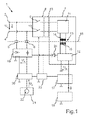
- FIG. 1 illustrated by a block diagram and denoted overall by 1 circuit arrangement is in a household appliance, here for example in a washing machine, arranged and used to operate the household appliance.
- the circuit arrangement 1 comprises a circuit input 2 with a first input terminal 3 and a second input terminal 4. Between the input terminals 3, 4 there is an AC supply voltage U N. With the circuit input 2, two Y-capacitors 5, 6 are coupled. The Y capacitors 5, 6 are used to achieve a galvanic decoupling to the circuit input 2. The Y capacitors 5, 6 can also be made double in both branches.
- a power supply unit 7 can be coupled to the circuit input 2, namely via a switching unit 8.
- the power supply unit 7 is connected to the first input terminal 3 via a first electrical switch 9 of the switching unit 8 and to the second input terminal 4 via a second electrical switch 10 of the switching unit 8 coupled.
- one of the switches 9, 10 can be omitted, for example, only the second switch 10 or only the first switch 9 can be used. It is essential that the power supply 7 can be decoupled from the input 2 and coupled with this again.
- a line filter 43 (EMC filter) is connected.
- the power supply 7 includes a primary circuit 11 and a secondary circuit 12.
- the power supply 7 also includes a transformer 13, the first winding 14 of the primary circuit 11 and the second winding 15 is associated with the secondary circuit 12. So there is a galvanic isolation between the primary circuit 11 and the secondary circuit 12 before, namely by the transformer 13.
- a potential barrier between the network-side primary circuit 11 and the secondary circuit 12 is in Fig. 1 indicated by a dashed line 16.
- the secondary circuit 12 of the power supply 7 may - as is common for power supplies - have a rectifier and a capacitor.
- the power supply 7 provides an operating voltage U B , which is a DC voltage.
- a control device 17 is coupled, which is present in the household appliance for controlling its functions.
- the control device 17 may be formed by a microprocessor or comprise such a microprocessor.
- the power supply 7 and the operating voltage U B and other electrical consumers can be coupled, the in Fig. 1 not shown, namely in particular actuators, sensors and the like.
- An operating device 18 is coupled to the control device 17. By the operating device 18 17 input signals S are transmitted to the control device, for example, after making an input by an operator.
- the operator 18 may include, for example, a program selector for selecting different functions of the washing machine and a display for displaying the selected functions.
- a supply unit 19 is capacitively coupled to the circuit input 2, namely via the Y capacitors 5, 6.
- the supply unit 19 picks up the AC supply voltage U N and converts it into a supply extra low voltage U K.
- This supply extra low voltage U K represents a low DC voltage, which may for example be in a value range between 3 V and 5 V.
- the supply unit 19 comprises a rectifier and a buffer capacitor to which the supply extra low voltage U K is applied.
- the supply unit 19 thus represents a small transformerless power supply.
- the AC supply voltage U N is thus capacitively coupled, rectified and stored asivesskleinwear U K in the buffer capacitor.
- an evaluation unit 20 is coupled, which is supplied with the supply extra low voltage U K.
- the evaluation unit 20 is coupled to a touch or proximity sensor 21, which has a sensor electrode 22.
- a touch or proximity sensor 21 which has a sensor electrode 22.
- the capacitance of a capacitor having this electrode 22 changes. This change in the capacitance is then detected directly by the evaluation unit 20, namely on the basis of the change of a state change signal U z - be it in amplitude or frequency.
- the circuit arrangement 1 comprises a circuit 23, which is coupled both to the evaluation unit 20 and to the control device 17.
- the evaluation unit 20 and the control device 17 can switch the switching unit 8 via the circuit 23, namely by outputting corresponding current pulses.
- the electrical switches 9, 10 are, for example, bistable relays, which can be converted into the respective mechanically stable switching state by applying a current pulse. But they can also be simple relays.
- the circuit 23 is thereby supplied with the supply voltage U K from the supply unit 19 or, when the power supply 7 is turned on, with the operating voltage U B from the power supply 7. This is made possible by a connection of the circuit 23 on the one hand to the supply unit 19 and on the other hand via a diode 24 to the secondary circuit 12 of the power supply 7. This connection is designed in such a way that the supply unit 19 can also be supplied with electrical energy by the secondary circuit 12, namely via the diode 24.
- the control device 17 can convert the household appliance into the waiting state by opening the electrical switches 9, 10. This takes place after fulfillment of a predetermined criterion.
- the controller 17 monitors whether the predetermined criterion is met or not. If no input by an operator via the operating device 18 over a predetermined time interval, the control device 17 transfers the household appliance in the waiting state. With others In words, the control device 17 monitors whether input signals S are transmitted from the operating device 18 or not. If no input signals S are sent by the operating device 18 over the predetermined time interval, the predetermined criterion is fulfilled and the household appliance is put into the waiting state.
- the domestic appliance into the waiting state by sending a predetermined input signal S to the control device 17.
- a predetermined input signal S can be generated, for example, by actuating a button of the operating device 18.
- the household appliance is also put into the waiting state when a process - for example, a washing or drying process - has just finished. If a process is completed, the control device 17 transfers the household appliance into the waiting state by opening the switches 9, 10.
- the control device 17 is switched off. Then only the evaluation unit 20, the electrical switch 9, 10 close again and so transfer the household appliance in the active state. This is done after touching the touch or proximity sensor 21 or when an operator approaches the same sensor 21.
- the evaluation unit 20 can immediately close the electrical switches 9, 10 after the return of a previously failed supply voltage U N.
- the control device 17, which is thus directly supplied with electrical energy, can then either maintain the closed switching state of the switches 9, 10 or open the same switch 9, 10.
- the switches 9, 10 then remain in the closed switching state when a program of the household appliance previously started has been interrupted by the failure of the AC supply voltage U N. Then the program can be completed properly.
- the switches 9, 10 are then opened by the control device 17 if no program of the household appliance was active prior to the failure of the AC supply voltage U N. Then, the controller 17 is turned off, and the home appliance returns to the waiting state.
- Fig. 2 shows in a schematic representation of the evaluation unit 20 and the touch or proximity sensor 21.
- the evaluation unit 20 includes a microcontroller 25, a digital-to-analog converter 26 and an analog comparator 27.
- the negative input of the comparator 27 is connected to an output of the digital-analog Converter 26 is coupled, and the positive input of the comparator 27 is coupled to an output 28 of the touch or proximity sensor 21.
- Via an output 29, the evaluation unit 20 can act on the touch or proximity sensor with voltage pulses, namely from theusedskleinwear U K , this is the output 29 is connected to an input 30 of the touch or proximity sensor 21.
- the state change signal U z is transmitted.
- the capacitive touch or proximity sensor 21 comprises a PNP bipolar transistor 31, the emitter of which is coupled to the input 30 via an ohmic resistor 32.
- a control terminal 33 of the bipolar transistor 31 is coupled via an ohmic resistor 34 to the input 30 and via a resistor 35 to a capacitor 36.
- the sensor electrode 22 of the capacitor 36 is coupled to the input 30 via an ohmic resistor 37.
- the collector of the bipolar transistor 31 is connected to the output 28, as well as coupled via a parallel circuit of a capacitor 38 and an ohmic resistor 39 to a reference potential 40.
- the capacitance value of the capacitor 38 is 1 nF in the embodiment, but this capacitance value may be in a value range of 500 pF to 50 nF, more preferably in a value range of 800 pF to 10 nF. So the capacitance value of the capacitor 38 is relatively low.
- the capacitive touch or proximity sensor 21 will be explained in more detail below. If the capacitive touch or proximity sensor 21 - applied via the input 30 - with a succession of voltage pulses, so generates the contact or proximity sensor 21 at the output 28 also voltage pulses. The amplitude of these voltage pulses is then dependent on the capacitance of the capacitor 36.
- the sensor electrode 22 is an operating element: By approaching an object that leads to a different potential from the reference potential 40, in particular the potential of the earth, the capacitance of the capacitor 36 changed. So an operator can put a finger on the Sensor electrode 22 to change the capacitance of the capacitor 36 and thus to change the amplitude of the output from the touch or proximity sensor 21 voltage pulses.
- the relationship is that the amplitude of the voltage pulses outputted at the output 28 is higher when an operator operates the touch or proximity sensor 21, or when the finger is in the vicinity of the sensor electrode 22.
- the microcontroller 25 loads the touch or proximity sensor 21 at predetermined time intervals each with a predetermined number of voltage pulses, eg with two, three or four voltage pulses.
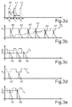
- a sequence of voltage pulses 41 delivered to the touch or proximity sensor 21 is shown in FIG Fig. 3a shown.
- the time t is plotted on the x-axis.
- the amplitude of the voltage pulses 41 is equal to the amplitude of the supply voltage U k .
- three voltage pulses 41 are delivered to the touch or proximity sensor 21 here.
- the pulse width t B in the exemplary embodiment is, for example, 20 ⁇ s.
- the pulse width t B may be in a value range from 10 ⁇ s to 50 ⁇ s.
- the time interval t A between two successive voltage pulses 41 in the exemplary embodiment is 60 ⁇ s.
- the time interval t A may be in a value range of 60 ⁇ s to 100 ⁇ s.
- Such sequence of three voltage pulses 41 is delivered to the touch or proximity sensor 21. Accordingly, the touch or proximity sensor 21 outputs voltage pulses, which are evaluated by the evaluation unit 20.
- the voltage pulses output by the touch or proximity sensor 21 are fed to the positive input of the comparator 27.
- a reference signal U R which is generated by the microcontroller 25. If the amplitude of the voltage pulses output by the touch or proximity sensor 21 (state change signal U z ) is greater than the amplitude of the reference signal U R , the comparator 27 outputs a logical "one". If the amplitude of the voltage pulse is smaller than the amplitude of the reference signal U R , the comparator 27 outputs a logical "zero".
- the reference signal U R is calibrated.
- the sequence of this calibration is in Fig. 3b shown.
- the microcontroller 25 acts on the touch or proximity sensor 21 with a sequence of voltage pulses.
- the touch or proximity sensor 21 accordingly outputs a sequence of voltage pulses 42 according to FIG Fig. 3b out.
- the microcontroller 25 gradually increases the amplitude of the reference signal U R until this amplitude exceeds the amplitude of the voltage pulses 42.
- the microcontroller 25 sets a first reference value R 1 of the reference signal U R.
- This first reference value R 1 is used at the beginning of the operation of the circuit arrangement 1 as a reference for the voltage pulses 42. Namely, depending on the first reference value R 1, a value range whose lower limit value is equal to the first reference value R 1 is determined. The upper limit can be predefined with respect to the lower limit. Thus, at the beginning of the operation of the circuit arrangement 1, a range of values of R 1 to Z 1 is determined.
- the microcontroller 25 checks every 100 ms whether or not an operator operates the touch or proximity sensor 21. Every 100 ms, the microcontroller 25 applies the touch or proximity sensor 21 with, for example, three voltage pulses 41. However, this time does not necessarily have to be 100 ms; It depends on the requirements of the operation as well as the power consumption in the waiting state. This time can be in a range from 5 ms to 200 ms. The microcontroller 25 then checks whether the amplitude of the voltage pulses 42 output by the contact or proximity sensor 21 lies within the specific value range from R 1 to Z 1 . If this is confirmed, then the household appliance is transferred to the active state.
- Fig. 3c An example of a correct actuation is in Fig. 3c shown.
- the microcontroller 25 changes the amplitude of the reference signal U R , namely between the lower limit value R 1 and the upper limit value Z 1 of the value range.
- Out Fig. 3c shows that the amplitude of the voltage pulses 42 is within the range of R 1 to Z 1 .
- the microcontroller 25 thus detects that an operator touch or Proximity sensor 21 is actuated to switch the circuit arrangement 1 in the active state.
- Fig. 3d the case is shown in which there is no actuation of the touch or proximity sensor 21. Namely, the amplitude of the voltage pulses 42 of the state change signal U z is less than the lower limit value R 1 of the value range.
- FIG Fig. 3e An example of improper operation of the touch or proximity sensor 21 is in FIG Fig. 3e displayed. How out Fig. 3e shows, the amplitude of the voltage pulses 42 is above the upper limit Z 1 of the range of values. The microcontroller 25 thus detects that an incorrect operation of the touch or proximity sensor 21 is present, and the circuit arrangement 1 is not transferred to the active state.
- the amplitude of the voltage pulses 42 output by the touch or proximity sensor 21 does not only depend on the capacitance of the capacitor 36 (FIG. Fig. 2 ), but also environmental conditions such as temperature and the like.
- the value range R 1 to Z 1 is adjusted with time; the range of values is thus always changed - thus the limit values are generally referred to below as R x and Z x .
- the lower limit value R x is determined again depending on the amplitude of the received voltage pulses 42.
- the upper limit Z x is then adjusted accordingly.
- R n R n - 1 + K * R n - 1 - A n .
- R n denotes the current lower limit of the value range
- R n-1 the previous lower limit of the range of values
- K a factor less than one
- a household appliance is provided with a circuit arrangement 1, which absorbs very little energy in the waiting state.
- a capacitive touch or proximity sensor 21 with associated evaluation unit 20 has been found that only about 50 mW are consumed in the waiting mode. This represents an improvement over the active state, in which 2 W to 20 W are consumed by the control device 17, as well as in the prior art, in which the power consumption is between 1 W and 3 W.
Landscapes
- Business, Economics & Management (AREA)
- Emergency Management (AREA)
- Engineering & Computer Science (AREA)
- Power Engineering (AREA)
- Electronic Switches (AREA)
Applications Claiming Priority (1)
| Application Number | Priority Date | Filing Date | Title |
|---|---|---|---|
| DE102009045968A DE102009045968A1 (de) | 2009-10-23 | 2009-10-23 | Haushaltsgerät und Verfahren zum Betreiben eines Haushaltsgeräts |
Publications (2)
| Publication Number | Publication Date |
|---|---|
| EP2315337A1 true EP2315337A1 (fr) | 2011-04-27 |
| EP2315337B1 EP2315337B1 (fr) | 2017-03-15 |
Family
ID=43616984
Family Applications (1)
| Application Number | Title | Priority Date | Filing Date |
|---|---|---|---|
| EP10187836.1A Active EP2315337B1 (fr) | 2009-10-23 | 2010-10-18 | Appareil ménager et procédé de fonctionnement d'un appareil ménager |
Country Status (2)
| Country | Link |
|---|---|
| EP (1) | EP2315337B1 (fr) |
| DE (1) | DE102009045968A1 (fr) |
Cited By (3)
| Publication number | Priority date | Publication date | Assignee | Title |
|---|---|---|---|---|
| EP2429078A1 (fr) * | 2010-09-08 | 2012-03-14 | BSH Bosch und Siemens Hausgeräte GmbH | Dispositif de commande capacitif pour un appareil ménager, appareil ménager et procédé de fonctionnement d'un dispositif de commande capacitif dans un appareil ménager |
| DE102012218316A1 (de) * | 2012-10-08 | 2014-04-10 | BSH Bosch und Siemens Hausgeräte GmbH | Bedienvorrichtung für ein Haushaltsgerät, Haushaltsgerät mit einer derartigen Bedienvorrichtung sowie Verfahren einer Bedienvorrichtung |
| CN117578351A (zh) * | 2024-01-16 | 2024-02-20 | 深圳市力生美半导体股份有限公司 | 开关电源及其控制方法、存储介质 |
Families Citing this family (2)
| Publication number | Priority date | Publication date | Assignee | Title |
|---|---|---|---|---|
| DE102015223672A1 (de) * | 2015-11-30 | 2017-06-01 | Lisa Dräxlmaier GmbH | Sensoreinrichtung zur Erkennung einer Betätigung eines Bedienelementes |
| DE102019205623A1 (de) * | 2019-04-17 | 2020-10-22 | BSH Hausgeräte GmbH | Netzfiltervorrichtung für ein Haushaltsgerät, Haushaltsgerät sowie Verfahren |
Citations (7)
| Publication number | Priority date | Publication date | Assignee | Title |
|---|---|---|---|---|
| US5194951A (en) * | 1991-12-16 | 1993-03-16 | Thomson Consumer Electronics, Inc. | Sleep timer arrangement for a television receiver |
| EP0689351A2 (fr) | 1994-06-23 | 1995-12-27 | NOKIA TECHNOLOGY GmbH | Circuit pour le mode de veille d'un dispositif de télécommande |
| EP0746100A1 (fr) * | 1995-06-01 | 1996-12-04 | Sentron Ag | Circuit pour faire fonctionner un capteur résistif, capacitif ou inductif |
| GB2341500A (en) * | 1998-09-14 | 2000-03-15 | Toshiba Kk | A power supply for an electronic device having a standby mode |
| EP1675265A2 (fr) * | 2004-12-22 | 2006-06-28 | Diehl AKO Stiftung & Co. KG | Circuit pour un commutateur capacitif à effleurement |
| DE102005041113A1 (de) | 2005-08-30 | 2007-03-01 | BSH Bosch und Siemens Hausgeräte GmbH | Kapazitiver Annäherungsschalter und Haushaltsgerät mit einem solchen |
| DE202006019991U1 (de) * | 2005-05-20 | 2007-06-28 | E.G.O. Elektro-Gerätebau GmbH | Schaltungsanordnung für einen kapazitiven Näherungsschalter |
Family Cites Families (4)
| Publication number | Priority date | Publication date | Assignee | Title |
|---|---|---|---|---|
| DE9308685U1 (de) * | 1993-06-11 | 1993-08-19 | Loewe Opta GmbH, 96317 Kronach | Fernsehempfangsgerät |
| JP2000123460A (ja) * | 1998-10-21 | 2000-04-28 | Hitachi Ltd | 記録再生装置 |
| DE102005044615A1 (de) * | 2005-09-19 | 2007-03-29 | Thanh Tu Duong | Fernbedienbare Schaltung mit extrem niedrigem Standby-Stromverbrauch im Mikrowatt Bereich |
| JP5104150B2 (ja) * | 2007-09-14 | 2012-12-19 | オムロン株式会社 | 検知装置および方法、並びにプログラム |
-
2009
- 2009-10-23 DE DE102009045968A patent/DE102009045968A1/de not_active Withdrawn
-
2010
- 2010-10-18 EP EP10187836.1A patent/EP2315337B1/fr active Active
Patent Citations (7)
| Publication number | Priority date | Publication date | Assignee | Title |
|---|---|---|---|---|
| US5194951A (en) * | 1991-12-16 | 1993-03-16 | Thomson Consumer Electronics, Inc. | Sleep timer arrangement for a television receiver |
| EP0689351A2 (fr) | 1994-06-23 | 1995-12-27 | NOKIA TECHNOLOGY GmbH | Circuit pour le mode de veille d'un dispositif de télécommande |
| EP0746100A1 (fr) * | 1995-06-01 | 1996-12-04 | Sentron Ag | Circuit pour faire fonctionner un capteur résistif, capacitif ou inductif |
| GB2341500A (en) * | 1998-09-14 | 2000-03-15 | Toshiba Kk | A power supply for an electronic device having a standby mode |
| EP1675265A2 (fr) * | 2004-12-22 | 2006-06-28 | Diehl AKO Stiftung & Co. KG | Circuit pour un commutateur capacitif à effleurement |
| DE202006019991U1 (de) * | 2005-05-20 | 2007-06-28 | E.G.O. Elektro-Gerätebau GmbH | Schaltungsanordnung für einen kapazitiven Näherungsschalter |
| DE102005041113A1 (de) | 2005-08-30 | 2007-03-01 | BSH Bosch und Siemens Hausgeräte GmbH | Kapazitiver Annäherungsschalter und Haushaltsgerät mit einem solchen |
Cited By (4)
| Publication number | Priority date | Publication date | Assignee | Title |
|---|---|---|---|---|
| EP2429078A1 (fr) * | 2010-09-08 | 2012-03-14 | BSH Bosch und Siemens Hausgeräte GmbH | Dispositif de commande capacitif pour un appareil ménager, appareil ménager et procédé de fonctionnement d'un dispositif de commande capacitif dans un appareil ménager |
| DE102012218316A1 (de) * | 2012-10-08 | 2014-04-10 | BSH Bosch und Siemens Hausgeräte GmbH | Bedienvorrichtung für ein Haushaltsgerät, Haushaltsgerät mit einer derartigen Bedienvorrichtung sowie Verfahren einer Bedienvorrichtung |
| CN117578351A (zh) * | 2024-01-16 | 2024-02-20 | 深圳市力生美半导体股份有限公司 | 开关电源及其控制方法、存储介质 |
| CN117578351B (zh) * | 2024-01-16 | 2024-04-05 | 深圳市力生美半导体股份有限公司 | 开关电源及其控制方法、存储介质 |
Also Published As
| Publication number | Publication date |
|---|---|
| EP2315337B1 (fr) | 2017-03-15 |
| DE102009045968A1 (de) | 2011-05-05 |
Similar Documents
| Publication | Publication Date | Title |
|---|---|---|
| EP2315337B1 (fr) | Appareil ménager et procédé de fonctionnement d'un appareil ménager | |
| EP2089653B1 (fr) | Procédé et montage permettant une commande fiable d'actionneurs, de capteurs et/ou de récepteurs dans un appareil électro-ménager les contenant | |
| EP2220737B1 (fr) | Circuit pour faire fonctionner un appareil électroménager | |
| DE10330451B3 (de) | Vorrichtung zum Wecken eines Steuergerätes | |
| EP1226474B1 (fr) | Dispositif de detection d'une coupure de courant dans un appareil domestique | |
| EP2315338B1 (fr) | Agencement de commutation (à l'arrêt) destiné au fonctionnement d'un appareil ménager et procédé correspondant | |
| DE60219240T2 (de) | Steuerungsschaltung für Stromversorgung und Kochvorrichtung | |
| EP2539912B1 (fr) | Configuration de circuit pour faire fonctionner un appareil électroménager, et procédé correspondant | |
| EP3726714B1 (fr) | Dispositif de filtre d4alimentation pour un appareil électroménager, appareil électroménager ainsi que procédé | |
| EP2491845A2 (fr) | Appareil électroménager | |
| EP2385608B1 (fr) | Entraînement de meuble électro-motorisé doté d'un dispositif d'alimentation en énergie | |
| EP2429078B1 (fr) | Dispositif de commande capacitif pour un appareil ménager, appareil ménager et procédé de fonctionnement d'un dispositif de commande capacitif dans un appareil ménager | |
| EP2246959A1 (fr) | Appareil ménager doté d'un dispositif de commutation et procédé correspondant | |
| DE102014216556B4 (de) | Schaltungsanordnung zum Steuern einer elektrisch angetriebenen Verriegelungseinrichtung für eine Tür eines Haushaltsgeräts, Haushaltsgerät sowie Verfahren hierfür | |
| EP3719985A1 (fr) | Appareil électroménager doté d'une unité électrique fonctionnelle ainsi que son procédé de fonctionnement | |
| DE102009010409B4 (de) | Steuervorrichtung | |
| DE10156342B4 (de) | Lastbetriebsanordnung und Betriebsverfahren für einen Lastkreis | |
| AT511125B1 (de) | Intelligentes Schaltgerät zum Sparen von Standby-Energie sowie Verfahren zur Steuerung des Schaltgerätes | |
| DE102016223499B4 (de) | Signalerfassungseinrichtung, Feldgerät, Prozessventilbaueinheit und Verfahren zum Erfassen eines Eingangssignals | |
| DE112022001378T5 (de) | Entstörfilter | |
| EP2538826B1 (fr) | Procédé de prise en compte des fluctuations de tension sur des appareils ménagers et dispositif à cet effet | |
| DE102018123382A1 (de) | Steuern der Entladung einer X-Kapazität | |
| EP2684276B1 (fr) | Appareil ménager ayant un mode de veille ainsi que procédé pour faire fonctionner un tel appareil ménager | |
| WO2016030264A1 (fr) | Convertisseur d'énergie cadencé pour alimenter en énergie une unité de commande électronique d'un appareil ménager | |
| WO2013030156A2 (fr) | Appareil ménager comprenant une circuiterie électrique ayant un mode de veille et un mode de fonctionnement ainsi que procédé pour faire fonctionner une circuiterie d'un appareil ménager |
Legal Events
| Date | Code | Title | Description |
|---|---|---|---|
| PUAI | Public reference made under article 153(3) epc to a published international application that has entered the european phase |
Free format text: ORIGINAL CODE: 0009012 |
|
| AK | Designated contracting states |
Kind code of ref document: A1 Designated state(s): AL AT BE BG CH CY CZ DE DK EE ES FI FR GB GR HR HU IE IS IT LI LT LU LV MC MK MT NL NO PL PT RO RS SE SI SK SM TR |
|
| AX | Request for extension of the european patent |
Extension state: BA ME |
|
| 17P | Request for examination filed |
Effective date: 20111027 |
|
| RAP1 | Party data changed (applicant data changed or rights of an application transferred) |
Owner name: BSH HAUSGERAETE GMBH |
|
| REG | Reference to a national code |
Ref country code: DE Ref legal event code: R079 Ref document number: 502010013300 Country of ref document: DE Free format text: PREVIOUS MAIN CLASS: H02J0009000000 Ipc: H03K0017960000 |
|
| GRAP | Despatch of communication of intention to grant a patent |
Free format text: ORIGINAL CODE: EPIDOSNIGR1 |
|
| RIC1 | Information provided on ipc code assigned before grant |
Ipc: H03K 17/96 20060101AFI20160916BHEP Ipc: H02J 9/00 20060101ALI20160916BHEP |
|
| INTG | Intention to grant announced |
Effective date: 20161021 |
|
| GRAS | Grant fee paid |
Free format text: ORIGINAL CODE: EPIDOSNIGR3 |
|
| GRAA | (expected) grant |
Free format text: ORIGINAL CODE: 0009210 |
|
| AK | Designated contracting states |
Kind code of ref document: B1 Designated state(s): AL AT BE BG CH CY CZ DE DK EE ES FI FR GB GR HR HU IE IS IT LI LT LU LV MC MK MT NL NO PL PT RO RS SE SI SK SM TR |
|
| REG | Reference to a national code |
Ref country code: CH Ref legal event code: EP Ref country code: GB Ref legal event code: FG4D Free format text: NOT ENGLISH |
|
| REG | Reference to a national code |
Ref country code: IE Ref legal event code: FG4D Free format text: LANGUAGE OF EP DOCUMENT: GERMAN |
|
| REG | Reference to a national code |
Ref country code: AT Ref legal event code: REF Ref document number: 876498 Country of ref document: AT Kind code of ref document: T Effective date: 20170415 |
|
| REG | Reference to a national code |
Ref country code: DE Ref legal event code: R096 Ref document number: 502010013300 Country of ref document: DE |
|
| REG | Reference to a national code |
Ref country code: NL Ref legal event code: MP Effective date: 20170315 |
|
| REG | Reference to a national code |
Ref country code: LT Ref legal event code: MG4D |
|
| PG25 | Lapsed in a contracting state [announced via postgrant information from national office to epo] |
Ref country code: GR Free format text: LAPSE BECAUSE OF FAILURE TO SUBMIT A TRANSLATION OF THE DESCRIPTION OR TO PAY THE FEE WITHIN THE PRESCRIBED TIME-LIMIT Effective date: 20170616 Ref country code: LT Free format text: LAPSE BECAUSE OF FAILURE TO SUBMIT A TRANSLATION OF THE DESCRIPTION OR TO PAY THE FEE WITHIN THE PRESCRIBED TIME-LIMIT Effective date: 20170315 Ref country code: HR Free format text: LAPSE BECAUSE OF FAILURE TO SUBMIT A TRANSLATION OF THE DESCRIPTION OR TO PAY THE FEE WITHIN THE PRESCRIBED TIME-LIMIT Effective date: 20170315 Ref country code: NO Free format text: LAPSE BECAUSE OF FAILURE TO SUBMIT A TRANSLATION OF THE DESCRIPTION OR TO PAY THE FEE WITHIN THE PRESCRIBED TIME-LIMIT Effective date: 20170615 Ref country code: FI Free format text: LAPSE BECAUSE OF FAILURE TO SUBMIT A TRANSLATION OF THE DESCRIPTION OR TO PAY THE FEE WITHIN THE PRESCRIBED TIME-LIMIT Effective date: 20170315 |
|
| PG25 | Lapsed in a contracting state [announced via postgrant information from national office to epo] |
Ref country code: LV Free format text: LAPSE BECAUSE OF FAILURE TO SUBMIT A TRANSLATION OF THE DESCRIPTION OR TO PAY THE FEE WITHIN THE PRESCRIBED TIME-LIMIT Effective date: 20170315 Ref country code: SE Free format text: LAPSE BECAUSE OF FAILURE TO SUBMIT A TRANSLATION OF THE DESCRIPTION OR TO PAY THE FEE WITHIN THE PRESCRIBED TIME-LIMIT Effective date: 20170315 Ref country code: RS Free format text: LAPSE BECAUSE OF FAILURE TO SUBMIT A TRANSLATION OF THE DESCRIPTION OR TO PAY THE FEE WITHIN THE PRESCRIBED TIME-LIMIT Effective date: 20170315 Ref country code: BG Free format text: LAPSE BECAUSE OF FAILURE TO SUBMIT A TRANSLATION OF THE DESCRIPTION OR TO PAY THE FEE WITHIN THE PRESCRIBED TIME-LIMIT Effective date: 20170615 |
|
| PG25 | Lapsed in a contracting state [announced via postgrant information from national office to epo] |
Ref country code: NL Free format text: LAPSE BECAUSE OF FAILURE TO SUBMIT A TRANSLATION OF THE DESCRIPTION OR TO PAY THE FEE WITHIN THE PRESCRIBED TIME-LIMIT Effective date: 20170315 |
|
| REG | Reference to a national code |
Ref country code: FR Ref legal event code: PLFP Year of fee payment: 8 |
|
| PG25 | Lapsed in a contracting state [announced via postgrant information from national office to epo] |
Ref country code: CZ Free format text: LAPSE BECAUSE OF FAILURE TO SUBMIT A TRANSLATION OF THE DESCRIPTION OR TO PAY THE FEE WITHIN THE PRESCRIBED TIME-LIMIT Effective date: 20170315 Ref country code: ES Free format text: LAPSE BECAUSE OF FAILURE TO SUBMIT A TRANSLATION OF THE DESCRIPTION OR TO PAY THE FEE WITHIN THE PRESCRIBED TIME-LIMIT Effective date: 20170315 Ref country code: RO Free format text: LAPSE BECAUSE OF FAILURE TO SUBMIT A TRANSLATION OF THE DESCRIPTION OR TO PAY THE FEE WITHIN THE PRESCRIBED TIME-LIMIT Effective date: 20170315 Ref country code: EE Free format text: LAPSE BECAUSE OF FAILURE TO SUBMIT A TRANSLATION OF THE DESCRIPTION OR TO PAY THE FEE WITHIN THE PRESCRIBED TIME-LIMIT Effective date: 20170315 Ref country code: SK Free format text: LAPSE BECAUSE OF FAILURE TO SUBMIT A TRANSLATION OF THE DESCRIPTION OR TO PAY THE FEE WITHIN THE PRESCRIBED TIME-LIMIT Effective date: 20170315 |
|
| PG25 | Lapsed in a contracting state [announced via postgrant information from national office to epo] |
Ref country code: PL Free format text: LAPSE BECAUSE OF FAILURE TO SUBMIT A TRANSLATION OF THE DESCRIPTION OR TO PAY THE FEE WITHIN THE PRESCRIBED TIME-LIMIT Effective date: 20170315 Ref country code: IS Free format text: LAPSE BECAUSE OF FAILURE TO SUBMIT A TRANSLATION OF THE DESCRIPTION OR TO PAY THE FEE WITHIN THE PRESCRIBED TIME-LIMIT Effective date: 20170715 Ref country code: SM Free format text: LAPSE BECAUSE OF FAILURE TO SUBMIT A TRANSLATION OF THE DESCRIPTION OR TO PAY THE FEE WITHIN THE PRESCRIBED TIME-LIMIT Effective date: 20170315 Ref country code: PT Free format text: LAPSE BECAUSE OF FAILURE TO SUBMIT A TRANSLATION OF THE DESCRIPTION OR TO PAY THE FEE WITHIN THE PRESCRIBED TIME-LIMIT Effective date: 20170717 |
|
| REG | Reference to a national code |
Ref country code: DE Ref legal event code: R097 Ref document number: 502010013300 Country of ref document: DE |
|
| PLBE | No opposition filed within time limit |
Free format text: ORIGINAL CODE: 0009261 |
|
| STAA | Information on the status of an ep patent application or granted ep patent |
Free format text: STATUS: NO OPPOSITION FILED WITHIN TIME LIMIT |
|
| PG25 | Lapsed in a contracting state [announced via postgrant information from national office to epo] |
Ref country code: DK Free format text: LAPSE BECAUSE OF FAILURE TO SUBMIT A TRANSLATION OF THE DESCRIPTION OR TO PAY THE FEE WITHIN THE PRESCRIBED TIME-LIMIT Effective date: 20170315 |
|
| 26N | No opposition filed |
Effective date: 20171218 |
|
| PG25 | Lapsed in a contracting state [announced via postgrant information from national office to epo] |
Ref country code: SI Free format text: LAPSE BECAUSE OF FAILURE TO SUBMIT A TRANSLATION OF THE DESCRIPTION OR TO PAY THE FEE WITHIN THE PRESCRIBED TIME-LIMIT Effective date: 20170315 |
|
| PG25 | Lapsed in a contracting state [announced via postgrant information from national office to epo] |
Ref country code: MC Free format text: LAPSE BECAUSE OF FAILURE TO SUBMIT A TRANSLATION OF THE DESCRIPTION OR TO PAY THE FEE WITHIN THE PRESCRIBED TIME-LIMIT Effective date: 20170315 |
|
| REG | Reference to a national code |
Ref country code: CH Ref legal event code: PL |
|
| REG | Reference to a national code |
Ref country code: IE Ref legal event code: MM4A |
|
| PG25 | Lapsed in a contracting state [announced via postgrant information from national office to epo] |
Ref country code: LI Free format text: LAPSE BECAUSE OF NON-PAYMENT OF DUE FEES Effective date: 20171031 Ref country code: LU Free format text: LAPSE BECAUSE OF NON-PAYMENT OF DUE FEES Effective date: 20171018 Ref country code: CH Free format text: LAPSE BECAUSE OF NON-PAYMENT OF DUE FEES Effective date: 20171031 |
|
| REG | Reference to a national code |
Ref country code: BE Ref legal event code: MM Effective date: 20171031 |
|
| PG25 | Lapsed in a contracting state [announced via postgrant information from national office to epo] |
Ref country code: BE Free format text: LAPSE BECAUSE OF NON-PAYMENT OF DUE FEES Effective date: 20171031 |
|
| PG25 | Lapsed in a contracting state [announced via postgrant information from national office to epo] |
Ref country code: MT Free format text: LAPSE BECAUSE OF FAILURE TO SUBMIT A TRANSLATION OF THE DESCRIPTION OR TO PAY THE FEE WITHIN THE PRESCRIBED TIME-LIMIT Effective date: 20170315 |
|
| REG | Reference to a national code |
Ref country code: FR Ref legal event code: PLFP Year of fee payment: 9 |
|
| PG25 | Lapsed in a contracting state [announced via postgrant information from national office to epo] |
Ref country code: IE Free format text: LAPSE BECAUSE OF NON-PAYMENT OF DUE FEES Effective date: 20171018 |
|
| REG | Reference to a national code |
Ref country code: AT Ref legal event code: MM01 Ref document number: 876498 Country of ref document: AT Kind code of ref document: T Effective date: 20171018 |
|
| PG25 | Lapsed in a contracting state [announced via postgrant information from national office to epo] |
Ref country code: AT Free format text: LAPSE BECAUSE OF NON-PAYMENT OF DUE FEES Effective date: 20171018 |
|
| PG25 | Lapsed in a contracting state [announced via postgrant information from national office to epo] |
Ref country code: HU Free format text: LAPSE BECAUSE OF FAILURE TO SUBMIT A TRANSLATION OF THE DESCRIPTION OR TO PAY THE FEE WITHIN THE PRESCRIBED TIME-LIMIT; INVALID AB INITIO Effective date: 20101018 |
|
| PG25 | Lapsed in a contracting state [announced via postgrant information from national office to epo] |
Ref country code: CY Free format text: LAPSE BECAUSE OF NON-PAYMENT OF DUE FEES Effective date: 20170315 |
|
| PG25 | Lapsed in a contracting state [announced via postgrant information from national office to epo] |
Ref country code: MK Free format text: LAPSE BECAUSE OF FAILURE TO SUBMIT A TRANSLATION OF THE DESCRIPTION OR TO PAY THE FEE WITHIN THE PRESCRIBED TIME-LIMIT Effective date: 20170315 |
|
| PG25 | Lapsed in a contracting state [announced via postgrant information from national office to epo] |
Ref country code: AL Free format text: LAPSE BECAUSE OF FAILURE TO SUBMIT A TRANSLATION OF THE DESCRIPTION OR TO PAY THE FEE WITHIN THE PRESCRIBED TIME-LIMIT Effective date: 20170315 |
|
| PGFP | Annual fee paid to national office [announced via postgrant information from national office to epo] |
Ref country code: GB Payment date: 20231025 Year of fee payment: 14 |
|
| PGFP | Annual fee paid to national office [announced via postgrant information from national office to epo] |
Ref country code: TR Payment date: 20231010 Year of fee payment: 14 Ref country code: IT Payment date: 20231031 Year of fee payment: 14 Ref country code: FR Payment date: 20231023 Year of fee payment: 14 Ref country code: DE Payment date: 20231031 Year of fee payment: 14 |