EP2314384B1 - Extruder - Google Patents
Extruder Download PDFInfo
- Publication number
- EP2314384B1 EP2314384B1 EP10180712.1A EP10180712A EP2314384B1 EP 2314384 B1 EP2314384 B1 EP 2314384B1 EP 10180712 A EP10180712 A EP 10180712A EP 2314384 B1 EP2314384 B1 EP 2314384B1
- Authority
- EP
- European Patent Office
- Prior art keywords
- piston rod
- actuating element
- control method
- motor
- control unit
- Prior art date
- Legal status (The legal status is an assumption and is not a legal conclusion. Google has not performed a legal analysis and makes no representation as to the accuracy of the status listed.)
- Active
Links
- 238000000034 method Methods 0.000 claims description 37
- 238000001514 detection method Methods 0.000 claims description 12
- 238000001125 extrusion Methods 0.000 description 8
- 238000010586 diagram Methods 0.000 description 5
- 238000002156 mixing Methods 0.000 description 5
- 239000011888 foil Substances 0.000 description 2
- 238000003780 insertion Methods 0.000 description 2
- 230000037431 insertion Effects 0.000 description 2
- 239000004570 mortar (masonry) Substances 0.000 description 2
- 238000011144 upstream manufacturing Methods 0.000 description 2
- 230000001419 dependent effect Effects 0.000 description 1
- 238000011161 development Methods 0.000 description 1
- 230000018109 developmental process Effects 0.000 description 1
- 230000007613 environmental effect Effects 0.000 description 1
- 230000007257 malfunction Effects 0.000 description 1
- 239000000463 material Substances 0.000 description 1
- 239000000523 sample Substances 0.000 description 1
- 239000000565 sealant Substances 0.000 description 1
- 239000007787 solid Substances 0.000 description 1
- 230000009466 transformation Effects 0.000 description 1
Images

Classifications
-
- B—PERFORMING OPERATIONS; TRANSPORTING
- B29—WORKING OF PLASTICS; WORKING OF SUBSTANCES IN A PLASTIC STATE IN GENERAL
- B29C—SHAPING OR JOINING OF PLASTICS; SHAPING OF MATERIAL IN A PLASTIC STATE, NOT OTHERWISE PROVIDED FOR; AFTER-TREATMENT OF THE SHAPED PRODUCTS, e.g. REPAIRING
- B29C48/00—Extrusion moulding, i.e. expressing the moulding material through a die or nozzle which imparts the desired form; Apparatus therefor
- B29C48/25—Component parts, details or accessories; Auxiliary operations
- B29C48/92—Measuring, controlling or regulating
-
- B—PERFORMING OPERATIONS; TRANSPORTING
- B05—SPRAYING OR ATOMISING IN GENERAL; APPLYING FLUENT MATERIALS TO SURFACES, IN GENERAL
- B05C—APPARATUS FOR APPLYING FLUENT MATERIALS TO SURFACES, IN GENERAL
- B05C17/00—Hand tools or apparatus using hand held tools, for applying liquids or other fluent materials to, for spreading applied liquids or other fluent materials on, or for partially removing applied liquids or other fluent materials from, surfaces
- B05C17/005—Hand tools or apparatus using hand held tools, for applying liquids or other fluent materials to, for spreading applied liquids or other fluent materials on, or for partially removing applied liquids or other fluent materials from, surfaces for discharging material from a reservoir or container located in or on the hand tool through an outlet orifice by pressure without using surface contacting members like pads or brushes
- B05C17/01—Hand tools or apparatus using hand held tools, for applying liquids or other fluent materials to, for spreading applied liquids or other fluent materials on, or for partially removing applied liquids or other fluent materials from, surfaces for discharging material from a reservoir or container located in or on the hand tool through an outlet orifice by pressure without using surface contacting members like pads or brushes with manually mechanically or electrically actuated piston or the like
- B05C17/0103—Hand tools or apparatus using hand held tools, for applying liquids or other fluent materials to, for spreading applied liquids or other fluent materials on, or for partially removing applied liquids or other fluent materials from, surfaces for discharging material from a reservoir or container located in or on the hand tool through an outlet orifice by pressure without using surface contacting members like pads or brushes with manually mechanically or electrically actuated piston or the like with electrically actuated piston or the like
-
- B—PERFORMING OPERATIONS; TRANSPORTING
- B29—WORKING OF PLASTICS; WORKING OF SUBSTANCES IN A PLASTIC STATE IN GENERAL
- B29C—SHAPING OR JOINING OF PLASTICS; SHAPING OF MATERIAL IN A PLASTIC STATE, NOT OTHERWISE PROVIDED FOR; AFTER-TREATMENT OF THE SHAPED PRODUCTS, e.g. REPAIRING
- B29C48/00—Extrusion moulding, i.e. expressing the moulding material through a die or nozzle which imparts the desired form; Apparatus therefor
- B29C48/02—Small extruding apparatus, e.g. handheld, toy or laboratory extruders
-
- F—MECHANICAL ENGINEERING; LIGHTING; HEATING; WEAPONS; BLASTING
- F15—FLUID-PRESSURE ACTUATORS; HYDRAULICS OR PNEUMATICS IN GENERAL
- F15B—SYSTEMS ACTING BY MEANS OF FLUIDS IN GENERAL; FLUID-PRESSURE ACTUATORS, e.g. SERVOMOTORS; DETAILS OF FLUID-PRESSURE SYSTEMS, NOT OTHERWISE PROVIDED FOR
- F15B15/00—Fluid-actuated devices for displacing a member from one position to another; Gearing associated therewith
- F15B15/08—Characterised by the construction of the motor unit
-
- B—PERFORMING OPERATIONS; TRANSPORTING
- B29—WORKING OF PLASTICS; WORKING OF SUBSTANCES IN A PLASTIC STATE IN GENERAL
- B29C—SHAPING OR JOINING OF PLASTICS; SHAPING OF MATERIAL IN A PLASTIC STATE, NOT OTHERWISE PROVIDED FOR; AFTER-TREATMENT OF THE SHAPED PRODUCTS, e.g. REPAIRING
- B29C2948/00—Indexing scheme relating to extrusion moulding
- B29C2948/92—Measuring, controlling or regulating
- B29C2948/92009—Measured parameter
- B29C2948/92076—Position, e.g. linear or angular
-
- B—PERFORMING OPERATIONS; TRANSPORTING
- B29—WORKING OF PLASTICS; WORKING OF SUBSTANCES IN A PLASTIC STATE IN GENERAL
- B29C—SHAPING OR JOINING OF PLASTICS; SHAPING OF MATERIAL IN A PLASTIC STATE, NOT OTHERWISE PROVIDED FOR; AFTER-TREATMENT OF THE SHAPED PRODUCTS, e.g. REPAIRING
- B29C2948/00—Indexing scheme relating to extrusion moulding
- B29C2948/92—Measuring, controlling or regulating
- B29C2948/92504—Controlled parameter
- B29C2948/92542—Energy, power, electric current or voltage
-
- B—PERFORMING OPERATIONS; TRANSPORTING
- B29—WORKING OF PLASTICS; WORKING OF SUBSTANCES IN A PLASTIC STATE IN GENERAL
- B29C—SHAPING OR JOINING OF PLASTICS; SHAPING OF MATERIAL IN A PLASTIC STATE, NOT OTHERWISE PROVIDED FOR; AFTER-TREATMENT OF THE SHAPED PRODUCTS, e.g. REPAIRING
- B29C2948/00—Indexing scheme relating to extrusion moulding
- B29C2948/92—Measuring, controlling or regulating
- B29C2948/92504—Controlled parameter
- B29C2948/92561—Time, e.g. start, termination, duration or interruption
-
- B—PERFORMING OPERATIONS; TRANSPORTING
- B29—WORKING OF PLASTICS; WORKING OF SUBSTANCES IN A PLASTIC STATE IN GENERAL
- B29C—SHAPING OR JOINING OF PLASTICS; SHAPING OF MATERIAL IN A PLASTIC STATE, NOT OTHERWISE PROVIDED FOR; AFTER-TREATMENT OF THE SHAPED PRODUCTS, e.g. REPAIRING
- B29C2948/00—Indexing scheme relating to extrusion moulding
- B29C2948/92—Measuring, controlling or regulating
- B29C2948/92504—Controlled parameter
- B29C2948/92571—Position, e.g. linear or angular
-
- B—PERFORMING OPERATIONS; TRANSPORTING
- B29—WORKING OF PLASTICS; WORKING OF SUBSTANCES IN A PLASTIC STATE IN GENERAL
- B29C—SHAPING OR JOINING OF PLASTICS; SHAPING OF MATERIAL IN A PLASTIC STATE, NOT OTHERWISE PROVIDED FOR; AFTER-TREATMENT OF THE SHAPED PRODUCTS, e.g. REPAIRING
- B29C2948/00—Indexing scheme relating to extrusion moulding
- B29C2948/92—Measuring, controlling or regulating
- B29C2948/92819—Location or phase of control
- B29C2948/92952—Drive section, e.g. gearbox, motor or drive fluids
-
- B—PERFORMING OPERATIONS; TRANSPORTING
- B29—WORKING OF PLASTICS; WORKING OF SUBSTANCES IN A PLASTIC STATE IN GENERAL
- B29C—SHAPING OR JOINING OF PLASTICS; SHAPING OF MATERIAL IN A PLASTIC STATE, NOT OTHERWISE PROVIDED FOR; AFTER-TREATMENT OF THE SHAPED PRODUCTS, e.g. REPAIRING
- B29C31/00—Handling, e.g. feeding of the material to be shaped, storage of plastics material before moulding; Automation, i.e. automated handling lines in plastics processing plants, e.g. using manipulators or robots
- B29C31/02—Dispensing from vessels, e.g. hoppers
-
- F—MECHANICAL ENGINEERING; LIGHTING; HEATING; WEAPONS; BLASTING
- F15—FLUID-PRESSURE ACTUATORS; HYDRAULICS OR PNEUMATICS IN GENERAL
- F15B—SYSTEMS ACTING BY MEANS OF FLUIDS IN GENERAL; FLUID-PRESSURE ACTUATORS, e.g. SERVOMOTORS; DETAILS OF FLUID-PRESSURE SYSTEMS, NOT OTHERWISE PROVIDED FOR
- F15B15/00—Fluid-actuated devices for displacing a member from one position to another; Gearing associated therewith
- F15B15/08—Characterised by the construction of the motor unit
- F15B15/14—Characterised by the construction of the motor unit of the straight-cylinder type
- F15B15/1423—Component parts; Constructional details
- F15B15/1447—Pistons; Piston to piston rod assemblies
Definitions
- the invention relates to a control method for controlling a squeezing device for mass-containing containers according to the preamble of patent claim 1.
- Containers include, for example cartridges with one or more receiving spaces for one or more components of the mass to be applied, the direct or z.
- B. in foil bags are provided in the receiving spaces of the cartridge.
- the term "container” also includes foil bags filled with one or more components of the mass to be delivered, which are inserted into a separate receiving body or arranged on the ejection device.
- a squeezing device for mass-containing container which has a receiving space for the container, a displaceable relative to the receiving space piston rod, a motor for moving the piston rod, an actuating element for generating a control signal upon actuation of the actuating element and a control unit for controlling the motor.
- the mass in the container pressurized and squeezed out through an outlet opening of the container.
- the piston rod is moved back by an arbitrary return travel determined by the control unit at the end of the squeezing operation.
- two control variables must be set by the user, which should be selected in particular with regard to the type of container and the environmental conditions.
- a disadvantage of the known solution is that the user has to make two settings, which needs both hands during the Auspressvorgangs. Next to the elaborate handling is a constant dosage when applying the mass with the known extrusion device is not given. Further, the actuator must be sufficiently solid formed by the arrangement within the connection between the power source and the engine to switch the engine power can.
- a generic control method for a squeezing device for mass-containing container goes from the nearest US2008 / 047974A1 out. Further control methods for extrusion devices for mass-containing containers are US 5,672,155 A , of the US2004 / 045982 A1 and the DE 20 2004 003 925 U1 known.
- the object of the invention is to provide a control method for a squeezing device for mass-containing container, with the damage to the squeezing, especially after inserting a new container, is prevented.
- a control method is characterized in that the position of the at least one piston rod is detected after completion of the forward movement and the return travel to be performed is adjusted according to the maximum available travel, provided that it is smaller than the predetermined return travel.
- control unit includes a power assembly for connecting the motor to a power supply and a separate signal input electrically connected to the actuator, and the power assembly connects the motor to the power supply in accordance with the control signal at the first signal input.
- the control unit comprises a control assembly and acts by means of the actuator and its own logic on the power assembly, which connects the motor to the power supply. Accordingly small and simple, the actuator can be formed.
- the actuator requires only a small space within the housing of the squeezing and is inexpensive to produce. Due to the low current can be used for the electrical connection between the actuator and the control unit cables with a small cross section, which require less space within the housing of the squeezing and are cheap to shop.
- the actuator is z.
- a switch and advantageously a button which are formed, for example, electromechanical.
- the power source includes, for example, a mains cable connected to a power cable or an advantageously rechargeable battery, which is further advantageous exchangeable on a housing of the squeezing device can be arranged.
- the motor is, for example, a brush motor or a brushless motor, which is a DC motor or an AC motor depending on the type of the current drawn and, if necessary, its transformation.
- the actuating element is additionally a speed controller, so that the speed of the motor is adjusted as a function of the distance traveled on actuation of the actuating element.
- the actuator is for this purpose advantageously an electromechanical probe comprising a potentiometer.
- a Dosiereinstelltechnik is provided for adjusting the amount to be applied per completed stroke of the mass, which is electrically connected via a separate signal input to the control unit with this. Since the Dosiereinstelltechnik is directly connected to the control unit and thus located outside the connection between the power source and the motor, it only needs to be supplied with an auxiliary power. Correspondingly small and simple, the Dosiereinstelltechnik be formed.
- the Dosiereinstelltechnik is a potentiometer.
- the Dosiereinstellü advantageously has a position "zero”, in which upon actuation of the actuating element, the motor is not connected to the power source, and a position “infinite”, in which the same when operating the actuating element to the release of the same mass is applied. Intermediate positions can also be set between these two positions on the dosing setting unit, so that a correspondingly defined quantity of the mass to be squeezed out is applied during the actuation of the actuating element by the squeezing device.
- a position detection unit for detecting the position of the at least one piston rod is provided, which is electrically connected via a separate signal input to the control unit with this. Since the position detection unit is connected directly to the control unit and thus arranged outside the connection between the power source and the motor, it only needs to be supplied with an auxiliary current. Accordingly, small and simple, the position detection unit can be formed.
- the position detection unit comprises a potentiometer. On the basis of the position detection unit, the position of the at least one piston rod can be determined at any time during the squeezing process.
- a display unit is provided, which is electrically connected to the control unit and which generates a perceptible by the user signal after reaching the complete stroke.
- the user can determine how much of the mass to be squeezed has already been applied or how much of the mass to be squeezed is still available for further squeezing operations.
- the display unit via a separate signal input to the control unit with this electrically connected.
- the display unit is electrically connected via an electrical component of the extrusion device, for example via the position detection unit to the control unit.
- the display unit generates an acoustic signal which is easily perceivable by the user.
- the display unit comprises a visually perceptible display which can serve as a level indicator.
- the control unit is preceded by at least one voltage regulator, which transforms the current of the current source, for example, from alternating current to direct current, or adapts the current voltage from the current source to the voltage of the components of the expressing device.
- a voltage regulator advantageously limits the voltage from the power source for the control unit.
- a further voltage regulator upstream of the corresponding components can limit the maximum voltage of the following components and can provide additional safety if a pulse width modulation also effective as a voltage regulator should be faulty.
- a fuse advantageously an electronic fuse provided, which monitors the maximum voltage within the extrusion device.
- the arrangement of an upstream voltage regulator can use a battery with a voltage which is greater than the voltage of the components of the squeezing device for which it is designed.
- longer operating times of a battery-operated squeezing device can be realized and prevented in the event of a falling operating voltage, for example of the battery, which leads to power losses or characteristic changes in the connected motor.
- the at least one piston rod is thus automatically retracted when the forward movement or the advance of the at least one piston rod until to generate an overpressure in the container took.
- the predetermined return travel is particularly dependent on the geometric conditions of the container and the Auspress the mass to be squeezed out.
- the predetermined period of time is determined according to the Auspress the mass to be squeezed out.
- the predetermined time period advantageously corresponds to the time during the squeezing process, in which a pressure is built up in the container, which would lead to a subsequent flow of the mass to be squeezed out after the end of the squeezing process.
- the predetermined period of time is advantageously in the range of 0.8 to 2-0 seconds.
- the position of the at least one piston rod is detected after completion of the forward movement and adapted to be performed return path corresponding to the maximum available path, if this is smaller than the predetermined return path.
- the squeezing device has a rear wall section which delimits the receiving space and through which the at least one piston rod passes. Without the adjustment of the return path, the at least one piston rod could jam with this wall portion, so that the wall portion and / or the at least one piston rod are damaged. If necessary, this leads to malfunctions up to a total failure of the squeezing device.
- the amount of mass to be applied per stroke completed is preferably set via the dosing setting unit, and upon renewed actuation of the actuating element, the at least one piston rod is advanced by the sum of the path resulting from the presetting and the previous return travel. This ensures the application of a reproducible amount of the curable composition over the entire Auspressvorgang.
- the at least one piston rod is advanced by a maximum of the sum of the remaining distance remaining and the eventual return path.
- the dosing process is restarted, with a possibly performed return travel is added and the at least one piston rod is advanced by the way out of the sum.
- the actuation time of the actuating element is detected only after at least one actuation of the actuating element twice.
- Versch the mass to be squeezed out to ensure a sufficient quality of the applied mass at the application site.
- Versch a certain amount
- this process is first filled prior to the effective dispensing of the mass and thus the adequate mixing z. As a multi-component mass ensured.
- the motor upon detecting a stoppage of forward movement of the at least one piston rod prior to completion of the complete stroke, the motor is automatically reversed for returning the at least one piston rod by a predetermined return travel, thereby overloading the engine and / or powertrain as well as the at least one Piston rod is avoided.
- the magnitude of the current drawn by the motor is monitored and, after exceeding a certain value, the switching operation is performed by the control unit.
- a standstill of the forward movement of the at least one piston rod is detected by a position detection unit, which sends a control signal to the control unit in the case of standstill.
- the return path at a standstill of the piston rod before the completion of the completed stroke greater than the return path at a predetermined time exceeding operating time of the actuating element, whereby the relatively large pressure in the container is advantageously reduced.
- the power module of the control unit only connects the motor to the power supply when a predefined threshold value is exceeded during the actuation of the actuating element, whereby a safety function against unintentional actuation of the ejection device is provided.
- the control unit detects the actuation of the actuation element actuated path and only after an actuation of, for example, 1 mm to 4 mm, the power assembly connected to connect the motor to the power supply.
- the actuator includes a potentiometer z.
- the threshold value can be set according to an electrical resistance detected by the control unit.
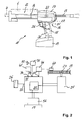
- the in the FIG. 1 illustrated squeezing device 11 for mass-containing container 6 has a receiving space 12 for the container 6, a relative to the receiving space 12 displaceable piston rod 13 and an electrically actuated squeezing device 16.
- a pressure piston 14 is provided for acting on the container 6 and the mass therein.
- the piston rod 13 is advanced into the receiving space 12 while the mass located in the container 6 is pressurized, so that it is pressed out through the outlet opening 7 of the container 6.
- the mass contained in the containing container 6 comprises one or more components.
- a mixing element is provided, which ensures complete mixing of the components for the exit from the outlet opening 7.
- the squeezing device 16 is arranged in a housing 17, from which a handle 18 extends. At the free end of the handle 18, a battery pack as a power supply 19 is releasably fixed.
- the ejection device 16 comprises a motor 21, which moves the piston rod 13 via a gear arrangement 22 with a toothing on the piston rod 13 meshing drive wheel 23.
- a button as an actuating element 26 for generating a control signal when operating the actuating element 26 is provided on the handle 18.
- a control unit 31 is further provided, which has a power unit 32 for connecting the motor 21 to the power supply 19 and a plurality of signal inputs 33, 34, 35, 36.
- the actuator 26 is electrically connected via a first signal input 33 to the control unit 31.
- the actuator 26 includes a potentiometer and is thus in addition to an on / off switch additionally a speed controller.
- a Dosiereinstelltechnik 41 is provided for adjusting the amount of mass to be applied per completed stroke, which is electrically connected via a second signal input 34 to the control unit 31 with this.
- the Dosiereinstelltechnik 41 comprises a potentiometer and has next to a position "zero", in which upon actuation of the actuating element 26, the motor 21 is not connected to the power supply 19 and thus no mass is applied, and a position "infinite", in which corresponding to the duration the operation of the actuating element 26 of the motor 21 is connected to the power supply 19, a plurality of adjustment options for applying a correspondingly defined amount of mass to be squeezed.
- a position detection unit 46 is provided for detecting the position of the piston rod 13, which comprises a sensor 47 arranged at the piston rod 13 and which is electrically connected to the control unit 31 via a third signal input 35.
- a display unit 51 is provided, which is electrically connected via a fourth signal input 36 to the control unit 31 with this and which after reaching the fully implemented hubs generates a user perceived signal.
- the display unit 51 comprises a loudspeaker 52 for generating an acoustic signal.
- the control unit 31 is preceded by a voltage regulator 56 which transforms the current voltage of the power supply 19 to the voltage for energizing the motor 21.
- a voltage regulator 56 which transforms the current voltage of the power supply 19 to the voltage for energizing the motor 21.
- an advantageous electronic voltage fuse is provided.
- the Verschs Dosiereinstelltechnik 41 is advantageously set to the "infinite" position and the actuator 26 is actuated until the quality of the discharged mass corresponds to the desired requirements. Usually, two to three consecutive advances of the piston rod 13 to do so.
- the desired dosage is set at Dosiereinstelltechnik 41 directly at the beginning and deployed by means of two to four strokes of Versch with the squeezing device 11.
- the quantity of the mass to be delivered per complete stroke is then set by means of the metering setting unit 41.
- the required travel W1 by which the piston rod 13 must be advanced, is determined by the control unit 31 in accordance with this presetting.
- the control unit 31 Upon actuation of the actuating element 26, this sends a control signal to the control unit 31, whereupon the power unit 32 connects the motor 21 to the power supply 19.
- the output shaft of the motor 21 drives via the gear assembly to the toothing of the piston rod 13 meshing drive wheel 23, whereupon the piston rod 13 to the way W1 is advanced (see Fig. 3 ).
- the power module 32 of the control unit 31 only then connects the motor 26 to the power supply 19 if, during the actuation of the actuating element 26, a predefined threshold value is exceeded.
- the actuation time of the actuating element 26, which corresponds to the duration of the holding down of the actuating element 26, is detected in this example only after the application of the Verschs by the control unit 31. If the actuation time of the actuating element 26 exceeds a predetermined time duration of, for example, one second, the piston rod 13 is retracted by automatic switching of the motor 21 by a defined return path S1 after reaching the path W1. In this case, the excess pressure generated in the container 6 is reduced in the Auspressvorgang and prevents overflow of the mass to be squeezed after completion of this Auspressvorgangs from the outlet opening 7.
- the piston rod 13 Upon a renewed actuation of the actuating element 26, the piston rod 13 is moved forward by the sum of the presetting resulting from the path W1 and the previously made return path S1, which despite the previously performed retraction of the piston rod 13, the defined according to the default amount of the mass to be squeezed out ,
- the position of the piston rod 13 is detected by the position detection unit 46 after completion of each forward movement.
- the first Auspressvorgang T1 is carried out and then the second Auspressvorgang T2 by the user z. B. interrupted by releasing the actuator 26, after which the piston rod 13 has completed the sum of the previously made return path S1 and W2 and before the stroke is completed. Only a partial pressing operation T21 of the entire pressing operation T2 was performed. Since the actuator 26 has been operated in the partial pressing operation T21 longer than the predetermined period of time, the piston rod 13 is moved back by the predetermined return path S1.
- the piston rod 13 is advanced by the sum of the previous return travel S1 and W3, when the user releases the actuating element 26 again. Only a partial pressing operation T22 of the entire pressing operation T2 was performed. Since the actuation time of the actuator 26 was below the value of the predetermined period of time, no relief of the container is required and there is no automatic retraction of the piston rod thirteenth
- the piston rod 13 is driven only to the W4, since then the path defined by the setting of Dosiereinstelltechnik 41 W1 was completely carried out by the piston rod 13 during the Auspressvorgangs T2 and thus deployed the desired amount of mass to be squeezed out is. Since the actuation time of the actuating element 26 has exceeded the predetermined period of time in the partial extrusion process T23, the piston rod 13 is automatically returned by the amount of the return travel S1.
- FIG. 5 the control method is shown when during a Auspressvorgang T2 z. B. from the position detection unit 46, a standstill of the forward movement of the piston rod 13 was detected before the completion of the fully performed stroke during the second Auspressvorgangs T2 (platform P) was.
- the motor 26 is automatically reversed for a return movement of the piston rod 13 by a predetermined return path S2, this return path S2 is greater than the predetermined return path S1, which is automatically executed when the predetermined time duration of the actuation time of the actuating element 26 is exceeded.
- the piston rod 13 is then advanced by the sum of the remaining distance W5 and the return path S2, so that after completion of the Auspressvorgangs T2, the desired amount of the mass to be squeezed is applied.
Description
Die Erfindung betrifft ein Steuerverfahren zum Steuern einer Auspressvorrichtung für Massen enthaltende Gebinde gemäss dem Oberbegriff des Patentanspruchs 1.The invention relates to a control method for controlling a squeezing device for mass-containing containers according to the preamble of patent claim 1.
Eine derartige Auspressvorrichtung dient dem Ausbringen von in Gebinden verpackten Massen, wie Mörtel- oder Dichtmassen, an einem Applikationsort. Gebinde umfassen beispielsweise Kartuschen mit einem oder mehreren Aufnahmeräumen für eine oder mehrere Komponenten der auszubringenden Masse, die direkt oder z. B. in Folienbeutel verpackt in den Aufnahmeräumen der Kartusche vorgesehen sind. Der Begriff "Gebinde" umfasst zudem mit einer oder mehreren Komponenten der auszubringenden Masse befüllte Folienbeutel, die in einen separaten oder an der Auspressvorrichtung angeordneten Aufnahmekörper eingesetzt werden.Such a squeezing device serves to dispense packaged masses, such as mortar or sealants, at an application site. Containers include, for example cartridges with one or more receiving spaces for one or more components of the mass to be applied, the direct or z. B. in foil bags are provided in the receiving spaces of the cartridge. The term "container" also includes foil bags filled with one or more components of the mass to be delivered, which are inserted into a separate receiving body or arranged on the ejection device.
Aus der
Nachteilig an der bekannten Lösung ist, dass der Anwender zwei Einstellungen vornehmen muss, welche während des Auspressvorgangs beide Hände braucht. Neben dem aufwändigen Handling ist eine konstante Dosierung beim Ausbringen der Masse mit der bekannten Auspressvorrichtung nicht gegeben. Weiter muss das Betätigungselement durch die Anordnung innerhalb der Verbindung zwischen der Stromquelle und dem Motor ausreichend massiv ausgebildet werden, um die Motorleistung schalten zu können.A disadvantage of the known solution is that the user has to make two settings, which needs both hands during the Auspressvorgangs. Next to the elaborate handling is a constant dosage when applying the mass with the known extrusion device is not given. Further, the actuator must be sufficiently solid formed by the arrangement within the connection between the power source and the engine to switch the engine power can.
Ein gattungsgemässes Steuerverfahren für eine Auspressvorrichtung für Massen enthaltende Gebinde geht aus der nächstkommenden
Aufgabe der Erfindung ist es, ein Steuerverfahren für eine Auspressvorrichtung für Massen enthaltende Gebinde zu schaffen, mit dem eine Beschädigung der Auspressvorrichtung, insbesondere nach dem Einlegen eines neuen Gebindes, verhindert wird.The object of the invention is to provide a control method for a squeezing device for mass-containing container, with the damage to the squeezing, especially after inserting a new container, is prevented.
Die Aufgabe wird durch die Merkmale des Anspruchs 1 gelöst. Vorteilhafte Weiterbildungen sind in den Unteransprüchen dargelegt.The object is solved by the features of claim 1. Advantageous developments are set forth in the subclaims.
Ein erfindungsgemässes Steuerverfahren ist dadurch gekennzeichnet, dass die Position der zumindest einen Kolbenstange nach Beendigung der Vorwärtsbewegung erfasst wird und der durchzuführende Rückfahrweg entsprechend dem maximal zur Verfügung stehenden Weg angepasst wird, sofern dieser kleiner als der vorbestimmte Rückfahrweg ist.A control method according to the invention is characterized in that the position of the at least one piston rod is detected after completion of the forward movement and the return travel to be performed is adjusted according to the maximum available travel, provided that it is smaller than the predetermined return travel.
Gemäss der Erfindung weist die Steuereinheit eine Leistungsbaugruppe zum Verbinden des Motors mit einer Stromversorgung sowie einen separaten Signaleingang aufweist, der mit dem Betätigungselement elektrisch verbunden ist, und die Leistungsbaugruppe verbindet entsprechend auf das Steuersignal am ersten Signaleingang den Motor mit der Stromversorgung.In accordance with the invention, the control unit includes a power assembly for connecting the motor to a power supply and a separate signal input electrically connected to the actuator, and the power assembly connects the motor to the power supply in accordance with the control signal at the first signal input.
Da das Betätigungselement direkt mit der Steuereinheit verbunden und somit ausserhalb der Verbindung zwischen der Stromquelle und dem Motor angeordnet ist, muss dieser nur mit einer Hilfsspannung versorgt werden. Die Steuereinheit umfasst eine Steuerbaugruppe und wirkt mittels dem Betätigungselementes und einer eigenen Logik auf die Leistungsbaugruppe ein, welche den Motor mit der Stromversorgung verbindet. Entsprechend klein und einfach kann das Betätigungselement ausgebildet werden. Das Betätigungselement, benötigt nur einen kleinen Bauraum innerhalb des Gehäuses der Auspressvorrichtung und ist kostengünstig herstellbar. Aufgrund des geringen Stroms können für die elektrische Verbindung zwischen dem Betätigungselement und der Steuereinheit Kabel mit einem kleinen Querschnitt verwendet werden, welche weniger Bauraum innerhalb des Gehäuses der Auspressvorrichtung benötigen und günstig im Einkauf sind.Since the actuating element is connected directly to the control unit and thus arranged outside the connection between the power source and the motor, it only needs to be supplied with an auxiliary voltage. The control unit comprises a control assembly and acts by means of the actuator and its own logic on the power assembly, which connects the motor to the power supply. Accordingly small and simple, the actuator can be formed. The actuator, requires only a small space within the housing of the squeezing and is inexpensive to produce. Due to the low current can be used for the electrical connection between the actuator and the control unit cables with a small cross section, which require less space within the housing of the squeezing and are cheap to shop.
Das Betätigungselement ist z. B. ein Schalter und vorteilhaft ein Taster, die beispielsweise elektromechanisch ausgebildet sind. Die Stromquelle umfasst beispielsweise ein mit einem Stromnetz verbundenes Netzkabel oder eine vorteilhaft wiederaufladbare Batterie, welche weiter vorteilhaft auswechselbar an einem Gehäuse der Auspressvorrichtung anordnenbar ist. Der Motor ist beispielsweise ein Bürstenmotor oder ein bürstenloser Motor, der in Abhängigkeit der Art des bezogenen Stroms und gegebenenfalls dessen Transformierung ein Gleichstrommotor oder ein Wechselstrommotor ist.The actuator is z. As a switch and advantageously a button, which are formed, for example, electromechanical. The power source includes, for example, a mains cable connected to a power cable or an advantageously rechargeable battery, which is further advantageous exchangeable on a housing of the squeezing device can be arranged. The motor is, for example, a brush motor or a brushless motor, which is a DC motor or an AC motor depending on the type of the current drawn and, if necessary, its transformation.
Vorzugsweise ist das Betätigungselement zusätzlich ein Geschwindigkeitsregler, so dass in Abhängigkeit des beim Betätigen des Betätigungselementes zurückgelegten Weges die Drehzahl des Motors angepasst wird. Dies ermöglicht dem Anwender bedarfsweise mit hoher Geschwindigkeit eine grosse Menge der auszupressenden Masse auszubringen oder z. B. für präzise Anwendungen mit geringer Geschwindigkeit gezielt kleine Mengen der der auszupressenden Masse auszubringen. Das Betätigungselement ist zu diesem Zweck vorteilhaft ein elektromechanischer Taster, der ein Potentiometer umfasst.Preferably, the actuating element is additionally a speed controller, so that the speed of the motor is adjusted as a function of the distance traveled on actuation of the actuating element. This allows the user, if necessary, at high speed to dispense a large amount of mass to be squeezed or z. B. for precise applications at low speed purposefully deploy small amounts of the mass to be squeezed out. The actuator is for this purpose advantageously an electromechanical probe comprising a potentiometer.
Bevorzugt ist eine Dosiereinstelleinheit zur Einstellung der pro vollständig durchgeführten Hub auszubringenden Menge der Masse vorgesehen, welche über einen separaten Signaleingang an der Steuereinheit mit dieser elektrisch verbunden ist. Da die Dosiereinstelleinheit direkt mit der Steuereinheit verbunden und somit ausserhalb der Verbindung zwischen der Stromquelle und dem Motor angeordnet ist, muss diese nur mit einem Hilfsstrom versorgt werden. Entsprechend klein und einfach kann die Dosiereinstelleinheit ausgebildet werden. Vorteilhaft ist die Dosiereinstelleinheit ein Potentiometer. Die Dosiereinstelleinheit weist vorteilhaft eine Stellung "Null", in welcher bei Betätigung des Betätigungselementes der Motor nicht mit der Stromquelle verbunden wird, und eine Stellung "unendlich" auf, in welcher beim Betätigen des Betätigungselementes bis zum Freigeben desselben permanent Masse ausgebracht wird. Zwischen diesen beiden Stellungen können an der Dosiereinstelleinheit auch Zwischenstellungen eingestellt werden, so dass bei der Betätigung des Betätigungselementes von der Auspressvorrichtung eine entsprechend definierte Menge der auszupressenden Masse ausgebracht wird.Preferably, a Dosiereinstelleinheit is provided for adjusting the amount to be applied per completed stroke of the mass, which is electrically connected via a separate signal input to the control unit with this. Since the Dosiereinstelleinheit is directly connected to the control unit and thus located outside the connection between the power source and the motor, it only needs to be supplied with an auxiliary power. Correspondingly small and simple, the Dosiereinstelleinheit be formed. Advantageously, the Dosiereinstelleinheit is a potentiometer. The Dosiereinstelleinheit advantageously has a position "zero", in which upon actuation of the actuating element, the motor is not connected to the power source, and a position "infinite", in which the same when operating the actuating element to the release of the same mass is applied. Intermediate positions can also be set between these two positions on the dosing setting unit, so that a correspondingly defined quantity of the mass to be squeezed out is applied during the actuation of the actuating element by the squeezing device.
Vorzugsweise ist eine Positionserfassungseinheit zum Erfassen der Position der zumindest einen Kolbenstange vorgesehen, welche über einen separaten Signaleingang an der Steuereinheit mit dieser elektrisch verbunden ist. Da die Positionserfassungseinheit direkt mit der Steuereinheit verbunden und somit ausserhalb der Verbindung zwischen der Stromquelle und dem Motor angeordnet ist, muss diese nur mit einem Hilfsstrom versorgt werden. Entsprechend klein und einfach kann die Positionserfassungseinheit ausgebildet werden. Vorteilhaft umfasst die Positionserfassungseinheit ein Potentiometer. Anhand der Positionserfassungseinheit kann zu jedem Zeitpunkt des Auspressvorgangs die Position der zumindest einen Kolbenstange festgestellt werden.Preferably, a position detection unit for detecting the position of the at least one piston rod is provided, which is electrically connected via a separate signal input to the control unit with this. Since the position detection unit is connected directly to the control unit and thus arranged outside the connection between the power source and the motor, it only needs to be supplied with an auxiliary current. Accordingly, small and simple, the position detection unit can be formed. Advantageously, the position detection unit comprises a potentiometer. On the basis of the position detection unit, the position of the at least one piston rod can be determined at any time during the squeezing process.
Bevorzugt ist eine Anzeigeeinheit vorgesehen, welche mit der Steuereinheit elektrisch verbunden ist und welche nach Erreichen des vollständig durchgeführten Hubs ein von dem Anwender wahrnehmbares Signal erzeugt. Somit kann der Anwender feststellen, wie viel der auszupressenden Masse bereits ausgebracht wurde beziehungsweise wie viel der auszupressenden Masse noch für weitere Auspressvorgänge zur Verfügung steht. Vorteilhaft ist die Anzeigeeinheit über einen separaten Signaleingang an der Steuereinheit mit dieser elektrisch verbunden. Alternativ ist die Anzeigeeinheit indirekt über ein elektrisches Bauteil der Auspressvorrichtung, beispielsweise über die Positionserfassungseinheit mit der Steuereinheit elektrisch verbunden.Preferably, a display unit is provided, which is electrically connected to the control unit and which generates a perceptible by the user signal after reaching the complete stroke. Thus, the user can determine how much of the mass to be squeezed has already been applied or how much of the mass to be squeezed is still available for further squeezing operations. Advantageously, the display unit via a separate signal input to the control unit with this electrically connected. Alternatively, the display unit is electrically connected via an electrical component of the extrusion device, for example via the position detection unit to the control unit.
Vorzugsweise erzeugt die Anzeigeeinheit ein akustisches Signal, welches einfach vom Anwender wahrnehmbar ist. Alternativ oder ergänzend dazu umfasst die Anzeigeeinheit eine visuell wahrnehmbare Anzeige, welche als eine Füllstandsanzeige dienen kann.Preferably, the display unit generates an acoustic signal which is easily perceivable by the user. Alternatively or additionally, the display unit comprises a visually perceptible display which can serve as a level indicator.
Bevorzugt ist der Steuereinheit zumindest ein Spannungsregler vorgeschaltet, welche den Strom der Stromquelle beispielsweise von Wechselstrom auf Gleichstrom umtransformiert oder die Stromspannung aus der Stromquelle auf die Stromspannung der Bauteile der Auspressvorrichtung anpasst. Ein Spannungsregler begrenzt vorteilhaft die Spannung aus der Stromquelle für die Steuereinheit. Des Weiteren kann ein weiterer den entsprechenden Bauteilen vorgeschalteter Spannungsregler die maximale Spannung der nachfolgenden Bauteile begrenzen und eine zusätzliche Sicherheit darstellen, falls eine ebenfalls als Spannungsregler wirksame Pulsweitenmodulation fehlerhaft sein sollte. Vorteilhaft ist zudem eine Sicherung, vorteilhaft eine elektronische Sicherung, vorgesehen, die die maximale Spannung innerhalb der Auspressvorrichtung überwacht. Ist die Auspressvorrichtung batteriebetrieben Auspressvorrichtung, kann durch die Anordnung eines vorgeschalteten Spannungsreglers eine Batterie mit einer Stromspannung verwendet werden, welche grösser als die Stromspannung der Bauteile der Auspressvorrichtung ist, für welche sie ausgelegt sind. Dadurch lassen sich längere Betriebszeiten einer batteriebetriebenen Auspressvorrichtung realisieren und bei einer fallenden Betriebsspannung beispielsweise der Batterie, welche zu Leistungseinbussen oder Charakteristikveränderungen des angeschlossenen Motors führen, verhindert werden.Preferably, the control unit is preceded by at least one voltage regulator, which transforms the current of the current source, for example, from alternating current to direct current, or adapts the current voltage from the current source to the voltage of the components of the expressing device. A voltage regulator advantageously limits the voltage from the power source for the control unit. Furthermore, a further voltage regulator upstream of the corresponding components can limit the maximum voltage of the following components and can provide additional safety if a pulse width modulation also effective as a voltage regulator should be faulty. Also advantageous is a fuse, advantageously an electronic fuse provided, which monitors the maximum voltage within the extrusion device. If the squeezing device is a battery-operated squeezing device, the arrangement of an upstream voltage regulator can use a battery with a voltage which is greater than the voltage of the components of the squeezing device for which it is designed. As a result, longer operating times of a battery-operated squeezing device can be realized and prevented in the event of a falling operating voltage, for example of the battery, which leads to power losses or characteristic changes in the connected motor.
Das gattungsgemässe Steuerverfahren zum Steuern einer Auspressvorrichtung für Massen enthaltende Gebinde, mit einem Aufnahmeraum für das Gebinde, mit zumindest einer gegenüber dem Aufnahmeraum verschiebbaren Kolbenstange, mit einem Motor zum Bewegen der zumindest einen Kolbenstange, mit einem Betätigungselement zum Erzeugen eines Steuersignals beim Betätigen des Betätigungselementes und mit einer Steuereinheit zum Steuern des Motors, welche eine Leistungsbaugruppe zum Verbinden des Motors mit einer Stromversorgung sowie einen separaten Signaleingang aufweist, der mit dem Betätigungselement elektrisch verbunden ist, wobei die Leistungsbaugruppe entsprechend auf das Steuersignal an diesem Signaleingang den Motor mit der Stromversorgung verbindet, umfasst die folgenden Schritte:
- a) Erfassen der Betätigungszeit, des Betätigungselementes durch die Steuereinheit und
- b) automatisches Ansteuern des Motors durch die Steuereinheit zum Zurückbewegen der zumindest einen Kolbenstange um einen vorbestimmten Rückfahrweg, sofern die Betätigungszeit eine vorbestimmte Zeitdauer überschreitet.
- a) detecting the actuation time, the actuating element by the control unit and
- b) automatic control of the motor by the control unit for moving back the at least one piston rod by a predetermined return path, if the actuation time exceeds a predetermined period of time.
Die zumindest eine Kolbenstange wird somit automatisch zurückgefahren, wenn die Vorwärtsbewegung beziehungsweise der Vorschub der zumindest einen Kolbenstange bis zur Erzeugung eines Überdrucks im Gebinde dauerte. Durch das Zurückfahren der zumindest einen Kolbenstange wird der unter Druck stehenden Masse ein Freiraum, an der der Auspressöffnung gegenüberliegenden Seite des Gebindes zur Verfügung gestellt, so dass sich die unter Druck stehende Masse in die Richtung dieser Seite ausdehnen kann und der Überdruck im Gebinde sich sofort abbaut. Dadurch wird ein Nachfliessen der auszupressenden Masse nach Beendigung des Auspressvorgangs sicher verhindert.The at least one piston rod is thus automatically retracted when the forward movement or the advance of the at least one piston rod until to generate an overpressure in the container took. By returning the at least one piston rod of the pressurized mass is a free space, provided at the opposite side of the Auspressöffnung the container, so that the pressurized mass can expand in the direction of this page and the pressure in the container immediately degrades. As a result, a subsequent flow of the mass to be squeezed out after completion of the squeezing process is reliably prevented.
Der vorbestimmte Rückfahrweg ist insbesondere von den geometrischen Verhältnissen des Gebindes sowie von dem Auspressverhalten der auszupressenden Masse abhängig.The predetermined return travel is particularly dependent on the geometric conditions of the container and the Auspressverhalten the mass to be squeezed out.
Die vorbestimmte Zeitdauer wird entsprechend dem Auspressverhalten der auszupressenden Masse bestimmt. Die vorbestimmte Zeitdauer entspricht vorteilhaft der Zeit beim Auspressvorgang, bei welcher ein Druck im Gebinde aufgebaut wird, der nach Beendigung des Auspressvorgangs zu einem Nachfliessen der auszupressenden Masse führen würde. Bei einer viskosen Mörtelmasse liegt die vorbestimmte Zeitdauer vorteilhaft im Bereich von 0.8 bis 2-0 Sekunden.The predetermined period of time is determined according to the Auspressverhalten the mass to be squeezed out. The predetermined time period advantageously corresponds to the time during the squeezing process, in which a pressure is built up in the container, which would lead to a subsequent flow of the mass to be squeezed out after the end of the squeezing process. For a viscous mortar composition, the predetermined period of time is advantageously in the range of 0.8 to 2-0 seconds.
Erfindungsgemäss wird die Position der zumindest einen Kolbenstange nach Beendigung der Vorwärtsbewegung erfasst und der durchzuführende Rückfahrweg entsprechend dem maximal zur Verfügung stehenden Weg angepasst, sofern dieser kleiner als der vorbestimmte Rückfahrweg ist. Damit wird eine Beschädigung der Auspressvorrichtung insbesondere nach dem Einlegen eines neuen Gebindes verhindert, wenn sich die zumindest eine Kolbenstange in Bezug auf ihre Vorwärtsbewegung in ihrer hintersten Stellung befindet. Oftmals weist die Auspressvorrichtung einen rückseitigen Wandabschnitt auf, welcher den Aufnahmeraum begrenzt und durch welchen die zumindest eine Kolbenstange hindurchgeführt ist. Ohne die Anpassung des Rückfahrweges könnte die zumindest eine Kolbenstange sich mit diesem Wandabschnitt verklemmen, so dass der Wandabschnitt und/oder die zumindest eine Kolbenstange beschädigt werden. Dies führt gegebenenfalls zu Funktionsstörungen bis zu einem Totalausfall der Auspressvorrichtung.According to the invention, the position of the at least one piston rod is detected after completion of the forward movement and adapted to be performed return path corresponding to the maximum available path, if this is smaller than the predetermined return path. This prevents damage to the squeezing device, in particular after the insertion of a new container, when the at least one piston rod is in its rearmost position with respect to its forward movement. Often, the squeezing device has a rear wall section which delimits the receiving space and through which the at least one piston rod passes. Without the adjustment of the return path, the at least one piston rod could jam with this wall portion, so that the wall portion and / or the at least one piston rod are damaged. If necessary, this leads to malfunctions up to a total failure of the squeezing device.
Bevorzugt wird über die Dosiereinstelleinheit die pro vollständig durchgeführten Hub auszubringende Menge der Masse eingestellt und bei einer erneuten Betätigung des Betätigungselementes die zumindest eine Kolbenstange um die Summe aus dem aus der Voreinstellung resultierenden Weg und dem zuvor erfolgten Rückfahrweg vorwärtsbewegt. Dadurch wird das Ausbringen einer reproduzierbaren Menge der aushärtbaren Masse über den gesamten Auspressvorgang gewährleistet.The amount of mass to be applied per stroke completed is preferably set via the dosing setting unit, and upon renewed actuation of the actuating element, the at least one piston rod is advanced by the sum of the path resulting from the presetting and the previous return travel. This ensures the application of a reproducible amount of the curable composition over the entire Auspressvorgang.
Vorzugsweise wird nach dem Loslassen des Betätigungselementes, bevor der Hub vollständig durchgeführt ist, bei einer erneuten Betätigung des Betätigungselementes die zumindest eine Kolbenstange maximal um die Summe aus dem verbleibenden Restweg sowie dem etwaig durchgeführten Rückfahrweg vorgeschoben. Dadurch sind eine beliebige Anzahl von Unterbrechungen während einem Dosiervorgang möglich, wobei nach dem Erreichen der vorbestimmten Menge der auszupressenden Masse der Auspressvorgang automatisch gestoppt wird.Preferably, after releasing the actuating element, before the stroke is completely carried out, in a renewed actuation of the actuating element, the at least one piston rod is advanced by a maximum of the sum of the remaining distance remaining and the eventual return path. As a result, any number of interruptions during a dosing process are possible, wherein after reaching the predetermined amount of the mass to be squeezed, the squeezing process is automatically stopped.
Alternativ dazu wird nach einem Unterbruch, der vor der Ausführung des kompletten Hubs erfolgt, der Dosiervorgang erneut gestartet, wobei ein etwaig durchgeführter Rückfahrweg aufaddiert und die zumindest eine Kolbenstange um den Weg aus der Summe vorwärtsbewegt wird.Alternatively, after an interruption, which takes place before the execution of the complete stroke, the dosing process is restarted, with a possibly performed return travel is added and the at least one piston rod is advanced by the way out of the sum.
Vorteilhaft wird nach dem Einlegen eines Gebindes in den Aufnahmeraum der Auspressvorrichtung die Betätigungszeit des Betätigungselementes erst nach zumindest einer zweimaligen Betätigung des Betätigungselementes erfasst. Zu Beginn des Auspressvorgangs kann zuerst eine bestimmte Menge, auch Verwurf genannt, der auszupressenden Masse ausgebracht werden, um eine ausreichende Qualität der ausgebrachten Masse am Applikationsort zu gewährleisten. Ist an der Auspressöffnung ein Mischelement vorgesehen, wird bei diesem Vorgang zuerst dieses vor dem effektiven Ausbringen der Masse gefüllt und dadurch die ausreichende Durchmischung z. B. einer mehrkomponentigen Masse sichergestellt.Advantageously, after the insertion of a container into the receiving space of the ejection device, the actuation time of the actuating element is detected only after at least one actuation of the actuating element twice. At the beginning of the Auspressvorgangs first a certain amount, also known as Verwurf, the mass to be squeezed out to ensure a sufficient quality of the applied mass at the application site. If a mixing element is provided at the ejection opening, this process is first filled prior to the effective dispensing of the mass and thus the adequate mixing z. As a multi-component mass ensured.
Vorzugsweise wird bei Erfassen eines Stillstandes der Vorwärtsbewegung der zumindest einen Kolbenstange vor der Beendigung des vollständig durchgeführten Hubs der Motor für eine Zurückbewegung der zumindest einen Kolbenstange um einem vorbestimmten Rückfahrweg automatisch umgeschaltet, womit eine Überlast des Motors und/oder des Antriebsstrangs wie auch der zumindest einen Kolbenstange vermieden wird. Beispielsweise wird die Grösse des von dem Motor bezogenen Stroms überwacht und nach dem Überschreiten eines bestimmten Wertes der Umschaltvorgang durch die Steuereinheit vorgenommen wird. Alternativ wird ein Stillstand der Vorwärtsbewegung der zumindest einen Kolbenstange von einer Positionserfassungseinheit erfasst, welche im Fall des Stillstands ein Steuersignal an die Steuereinheit sendet.Preferably, upon detecting a stoppage of forward movement of the at least one piston rod prior to completion of the complete stroke, the motor is automatically reversed for returning the at least one piston rod by a predetermined return travel, thereby overloading the engine and / or powertrain as well as the at least one Piston rod is avoided. By way of example, the magnitude of the current drawn by the motor is monitored and, after exceeding a certain value, the switching operation is performed by the control unit. Alternatively, a standstill of the forward movement of the at least one piston rod is detected by a position detection unit, which sends a control signal to the control unit in the case of standstill.
Bevorzugt ist der Rückfahrweg bei einem Stillstand der Kolbenstange vor der Beendigung des vollständig durchgeführten Hubs grösser als der Rückfahrweg bei einer die vorbestimmte Zeitdauer überschreitenden Betätigungszeit des Betätigungselementes, womit der verhältnismässig grosse Überdruck im Gebinde vorteilhaft abgebaut wird.Preferably, the return path at a standstill of the piston rod before the completion of the completed stroke greater than the return path at a predetermined time exceeding operating time of the actuating element, whereby the relatively large pressure in the container is advantageously reduced.
Vorzugsweise verbindet die Leistungsbaugruppe der Steuereinheit erst dann den Motor mit der Stromversorgung, wenn bei der Betätigung des Betätigungselementes ein vordefinierter Schwellwert überschritten wird, womit eine Sicherungsfunktion gegen eine unbeabsichtigte Betätigung der Auspressvorrichtung geschaffen ist. Beispielsweise wird von der Steuereinheit der bei der Betätigung des Betätigungselementes betätigte Weg erfasst und erst nach einem Betätigungsweg von beispielsweise 1 mm bis 4 mm, die Leistungsbaugruppe zum Verbinden des Motors mit der Stromversorgung geschaltet. Umfasst das Betätigungselement ein Potentiometer z. B. zur Geschwindigkeitsregulierung, kann der Schwellwert entsprechend eines von der Steuereinheit erfassten elektrischen Widerstandes festgelegt werden.Preferably, the power module of the control unit only connects the motor to the power supply when a predefined threshold value is exceeded during the actuation of the actuating element, whereby a safety function against unintentional actuation of the ejection device is provided. For example, the control unit detects the actuation of the actuation element actuated path and only after an actuation of, for example, 1 mm to 4 mm, the power assembly connected to connect the motor to the power supply. Does the actuator includes a potentiometer z. As for speed regulation, the threshold value can be set according to an electrical resistance detected by the control unit.
Die Erfindung wird nachstehend anhand eines Ausführungsbeispiels näher erläutert. Es zeigen:
- Fig. 1
- Eine Auspressvorrichtung in Seitenansicht;
- Fig. 2
- ein vereinfachtes Schaltschema der Auspressvorrichtung;
- Fig. 3
- ein schematisches Diagramm eines Auspressvorgangs;
- Fig. 4
- ein schematisches Diagramm eines Auspressvorgangs in einzelnen Teilschritten; und
- Fig. 5
- ein schematisches Diagramm eines Auspressvorgangs bei einem Stillstand der Kolbenstange während dem Auspressvorgang.
- Fig. 1
- A squeezing device in side view;
- Fig. 2
- a simplified circuit diagram of the squeezing device;
- Fig. 3
- a schematic diagram of a Auspressvorgangs;
- Fig. 4
- a schematic diagram of a Auspressvorgangs in individual substeps; and
- Fig. 5
- a schematic diagram of a Auspressvorgangs at a standstill of the piston rod during the Auspressvorgang.
Grundsätzlich sind in den Figuren gleiche Teile mit den gleichen Bezugszeichen versehen.Basically, the same parts are provided with the same reference numerals in the figures.
Die in der
Die Auspresseinrichtung 16 ist in einem Gehäuse 17 angeordnet, von dem sich ein Handgriff 18 erstreckt. Am freien Ende des Handgriffs 18 ist ein Batteriepack als Stromversorgung 19 lösbar festgelegt. Die Auspresseinrichtung 16 umfasst einen Motor 21, der über eine Getriebeanordnung 22 ein mit einer Zahnung an der Kolbenstange 13 kämmenden Antriebsrad 23 die Kolbenstange 13 bewegt.The squeezing
Weiter ist am Handgriff 18 ein Taster als Betätigungselement 26 zum Erzeugen eines Steuersignals beim Betätigen des Betätigungselementes 26 vorgesehen. Zum Steuern des Motors 21 ist weiter eine Steuereinheit 31 vorgesehen, die eine Leistungsbaugruppe 32 zum Verbinden des Motors 21 mit der Stromversorgung 19 sowie mehrere Signaleingänge 33, 34, 35, 36 aufweist.Further, a button as an
Wie in der
Weiter ist eine Dosiereinstelleinheit 41 zur Einstellung der pro vollständig durchgeführten Hub auszubringenden Menge der Masse vorgesehen, welche über einen zweiten Signaleingang 34 an der Steuereinheit 31 mit dieser elektrisch verbunden ist. Die Dosiereinstelleinheit 41 umfasst einen Potentiometer und weist neben einer Stellung "Null", in welcher bei Betätigung des Betätigungselementes 26 der Motor 21 nicht mit der Stromversorgung 19 verbunden und somit keine Masse ausgebracht wird, sowie einer Stellung "unendlich", in welcher entsprechend der Dauer der Betätigung des Betätigungselementes 26 der Motor 21 mit der Stromversorgung 19 verbunden ist, mehrere Einstellmöglichkeiten für das Ausbringen einer entsprechend definierten Menge der auszupressenden Masse auf.Further, a
Zudem ist eine Positionserfassungseinheit 46 zum Erfassen der Position der Kolbenstange 13 vorgesehen, die einen bei der Kolbenstange 13 angeordneten Sensor 47 umfasst und die über einen dritten Signaleingang 35 an der Steuereinheit 31 mit dieser elektrisch verbunden ist.In addition, a
Weiter ist eine Anzeigeeinheit 51 vorgesehen, welche über einen vierten Signaleingang 36 an der Steuereinheit 31 mit dieser elektrisch verbunden ist und welche nach Erreichen des vollständig durchgeführten Hubs ein von dem Anwender wahrnehmbares Signal erzeugt. Die Anzeigeeinheit 51 umfasst einen Lautsprecher 52 zum Erzeugen eines akustischen Signals.Further, a
Der Steuereinheit 31 ist ein Spannungsregler 56 vorgeschaltet, welcher die Stromspannung der Stromversorgung 19 auf die Stromspannung zur Bestromung des Motors 21 transformiert. Alternativ oder ergänzend zu einem oder mehrerer Spannungsregler 56 eine vorteilhaft elektronische Spannungssicherung vorgesehen.The
Das Steuerverfahren zum Steuern der Auspressvorrichtung 11 wird nachfolgend mit Bezug auf die
Nach dem Einlegen eines neuen oder eines teilgebrauchten Gebindes 6 in den Aufnahmeraum 12 der Auspressvorrichtung 11 wird vor dem eigentlichen Ausbringen der auszupressenden Masse am Applikationsort eine Menge derselben ausgebracht. Dieser vorgängig ausgebrachte Anteil beziehungsweise Verwurf der auszupressenden Masse dient insbesondere dem Füllen der Austrittsöffnung 7 und z. B. eines darin befindlichen Mischelementes.After inserting a new or a partially used container 6 in the receiving
Zum Ausbringen des Verwurfs wird die Dosiereinstelleinheit 41 vorteilhaft auf die Stellung "unendlich" gestellt und das Betätigungselement 26 solange betätigt, bis die Qualität der ausgebrachten Masse den gewünschten Erfordernissen entspricht. Üblicherweise reichen zwei bis drei hintereinander erfolgende Vorschübe der Kolbenstange 13 dazu aus.For dispensing the
Alternativ wird an der Dosiereinstelleinheit 41 direkt zu Beginn die gewünschte Dosierung eingestellt und mittels zwei bis vier Hüben der Verwurf mit der Auspressvorrichtung 11 ausgebracht.Alternatively, the desired dosage is set at
Wurde der Verwurf auf der Stellung "unendlich" der Dosiereinstelleinheit 41 ausgebracht, wird anschliessend mittels der Dosiereinstelleinheit 41 die pro vollständig ausgeführten Hub auszubringende Menge der Masse eingestellt. Aufgrund der bekannten Abmessungen des Gebindes und der bekannten Eigenschaften der auszupressenden Masse wird entsprechend dieser Voreinstellung von der Steuereinheit 31 der erforderliche Weg W1 bestimmt, um welchen die Kolbenstange 13 vorgeschoben werden muss. Bei der Betätigung des Betätigungselementes 26 sendet dieses ein Steuersignal an die Steuereinheit 31, worauf die Leistungsbaugruppe 32 den Motor 21 mit der Stromversorgung 19 verbindet. Die Abtriebswelle des Motors 21 treibt über die Getriebeanordnung das mit der Zahnung der Kolbenstange 13 kämmende Antriebsrad 23 an, worauf die Kolbenstange 13 um den Weg W1 vorgeschoben wird (siehe
Die Betätigungszeit des Betätigungselementes 26, welche der Dauer des Gedrückthaltens des Betätigungselementes 26 entspricht, wird in diesem Beispiel erst nach dem Ausbringen des Verwurfs durch die Steuereinheit 31 erfasst. Überschreitet dabei die Betätigungszeit des Betätigungselementes 26 eine vorbestimmte Zeitdauer von beispielsweise einer Sekunde, wird nach Erreichen des Weges W1 die Kolbenstange 13 durch automatisches Umschalten des Motors 21 um einen definierten Rückfahrweg S1 zurückgefahren. Dabei wird der beim Auspressvorgang erzeugte Überdruck im Gebinde 6 abgebaut und ein Nachfliessen der auszupressenden Masse nach Beendigung dieses Auspressvorgangs aus der Austrittsöffnung 7 verhindert.The actuation time of the
Bei einer erneuten Betätigung des Betätigungselementes 26 wird die Kolbenstange 13 um die Summe aus dem aus der Voreinstellung resultierenden Weg W1 und dem zuvor erfolgten Rückfahrweg S1 vorwärtsbewegt, womit trotz dem vorgängig durchgeführten Zurückfahren der Kolbenstange 13 die entsprechend der Voreinstellung definierte Menge der auszupressenden Masse ausgebracht wird.Upon a renewed actuation of the
Die vorgenannten Schritte werden solange wiederholt, bis die gewünschte Totalmenge der auszupressenden Masse ausgebracht ist.The above steps are repeated until the desired total amount of mass to be squeezed is applied.
Die Position der Kolbenstange 13 wird über die Positionserfassungseinheit 46 nach Beendigung jeder Vorwärtsbewegung erfasst. Wurde die Kolbenstange 13, z. B. zum Einlegen eines neuen Gebindes 6 in den Aufnahmeraum 12 der Auspressvorrichtung 11 ganz zurückgezogen und wurde bei der Betätigung des Betätigungselementes 26 die Kolbenstange 13 nur um einen geringen Weg vorgeschoben, wird der dann durchzuführende Rückfahrweg entsprechend dem maximal zur Verfügung stehenden Weg durch die Steuereinheit 31 angepasst, sofern dieser kleiner als der vorbestimmte Rückfahrweg S1 ist. Dadurch wird verhindert, dass sich die Kolbenstange 13 und insbesondere das Druckstück 14 sich mit dem Gehäuse 17 verklemmt beziehungsweise mit diesem verspannt.The position of the
Gemäss der
Bei einer erneuten Betätigung des Betätigungselementes 26 wird die Kolbenstange 13 um die Summe aus dem zuvor erfolgten Rückfahrweg S1 und W3 vorgefahren, als der Anwender das Betätigungselement 26 wieder loslässt. Es wurde nur ein Teilauspressvorgang T22 des gesamten Auspressvorgangs T2 durchgeführt. Da hier die Betätigungszeit des Betätigungselementes 26 unter dem Wert der vorbestimmten Zeitdauer lag, ist keine Entlastung des Gebindes erforderlich und es erfolgt kein automatisches Zurückfahren der Kolbenstange 13.Upon renewed actuation of the
Bei einer weiteren Betätigung des Betätigungselementes 26 wird die Kolbenstange 13 nur noch um den W4 vorgefahren, da dann der über die Einstellung der Dosiereinstelleinheit 41 definierte Weg W1 vollständig von der Kolbenstange 13 während dem Auspressvorgangs T2 durchgeführt wurde und somit die gewünschte Menge der auszupressenden Masse ausgebracht ist. Da beim Teilauspressvorgang T23 die Betätigungszeit des Betätigungselementes 26 die vorbestimmte Zeitdauer überschritten hat, erfolgt wieder ein automatisches Zurückfahren der Kolbenstange 13 um den Betrag des Rückfahrwegs S1.In a further actuation of the
Anschliessend wird bei einer erneuten Betätigung des Betätigungselementes 26 ein weiterer Auspressvorgang TX gestartet, der in einmal, wie beim Auspressvorgang T1 oder auch in mehreren Teilschritten wie der Auspressvorgang T2 erfolgen kann.Subsequently, upon another actuation of the
In der
In den Diagrammen wurden jeweils die Varianten des Steuerverfahrens beispielhaft anhand des zweiten Auspressvorgangs T2 dargelegt. Selbstverständlich erfolgen diese Varianten des Steuerverfahrens auch bei dem ersten oder einem der nachfolgenden Auspressvorgänge TX, wenn eine oder mehrere der vorgenannten Situationen auftreten.In the diagrams, in each case the variants of the control method were explained by way of example with reference to the second expressing process T2. Of course, these variants of the control method also take place during the first or one of the subsequent extrusion processes TX when one or more of the aforementioned situations occur.
Claims (12)
- Control method for controlling a dispensing device for paste containers (6) with a receiving space (12) for the container (6),
with at least one piston rod (13) displaceable with respect to the receiving space (12),
with a motor (21) for moving the at least one piston rod (13),
with an actuating element (26) for generating a control signal upon actuation of the actuating element (26), and
with a control unit (31) for controlling the motor (21), comprising a power unit (32) for connecting the motor (21) to a power supply (19) and a separate signal input (33) electrically connected to the actuating element (26), the power unit (32) connecting the motor (21) to the power supply (19) in response to the control signal at this signal input (33),
wherein the control method comprises the following steps:a) recording of the actuation time of the actuating element (26) by the control unit (31);b) automatic triggering of the motor (21) by the control unit (31) to retract the at least one piston rod (13) by a predetermined reverse travel (S1), if the actuation time exceeds a predetermined time period,characterized in that
the position of the at least one piston rod (13) after completing its forwards movement is detected and the reverse travel (S1) to be effected is adjusted to suit the maximum distance available if the latter is smaller than the predetermined reverse travel (S1). - Control method according to Claim 1, characterized in that the actuating element (26) is also a speed regulator.
- Control method according to Claim 1 or Claim 2, characterized in that a dosage setting unit (41) is provided for setting the quantity of paste to be dispensed per fully completed stroke, and is electrically connected to the control unit (31) via a separate signal input (34).
- Control method according to any one of Claims 1 to 3, characterized in that a position detection unit (46) is provided for detecting the position of the at least one piston rod (13), and is electrically connected to the control unit (31) via a separate signal input (35).
- Control method according to any one of Claims 1 to 4, characterized in that a display unit (51) is provided which is electrically connected to the control unit (31) and generates a signal to the user upon culmination of the full stroke.
- Control method according to Claim 5, characterized in that the display unit (51) generates an audible signal.
- Control method according to any one of Claims 1 to 6, characterized in that a voltage regulator (56) is connected ahead of the control unit (31).
- Control method according to Claim 3, characterized in that the quantity of paste to be dispensed per fully completed stroke is set by the dosage setting unit (41) and upon renewed actuation of the actuating element (26) the at least one piston rod (13) is moved forwards by the sum of the distance (W1) resulting from the initial setting and the reverse distance (S1) travelled.
- Control method according to Claim 8, characterized in that once the actuating element (26) has been released before a stroke has been fully completed, renewed actuation of the actuating element (26) advances the at least one piston rod (13) by not more than the sum of the residual travel remaining and any reverse distance travelled.
- Control method according to any one of Claims 1 to 9, characterized in that upon detection of a stop of the forwards motion of the at least one piston rod (13) before culmination of a full stroke, the motor (21) is automatically switched to reverse the at least one piston rod (13) through a predetermined reverse travel.
- Control method according to Claim 10, characterized in that the reverse travel due to a stop of the piston rod (13) before culmination of a full stroke is greater than that due to an actuation of the actuating element (26) for a time exceeding the predetermined time period.
- Control method according to any one of Claims 1 to 11, characterized in that the power unit (32) of the control unit (31) does not connect the motor (21) to the power supply (19) until a predefined threshold value has been exceeded upon actuation of the actuating element (26).
Applications Claiming Priority (1)
| Application Number | Priority Date | Filing Date | Title |
|---|---|---|---|
| DE102009045891A DE102009045891A1 (en) | 2009-10-21 | 2009-10-21 | squeezing |
Publications (2)
| Publication Number | Publication Date |
|---|---|
| EP2314384A1 EP2314384A1 (en) | 2011-04-27 |
| EP2314384B1 true EP2314384B1 (en) | 2014-12-31 |
Family
ID=43568747
Family Applications (1)
| Application Number | Title | Priority Date | Filing Date |
|---|---|---|---|
| EP10180712.1A Active EP2314384B1 (en) | 2009-10-21 | 2010-09-28 | Extruder |
Country Status (7)
| Country | Link |
|---|---|
| US (2) | US20110151042A1 (en) |
| EP (1) | EP2314384B1 (en) |
| JP (1) | JP5749913B2 (en) |
| CN (1) | CN102039260B (en) |
| CA (1) | CA2718324C (en) |
| DE (1) | DE102009045891A1 (en) |
| ES (1) | ES2529202T3 (en) |
Families Citing this family (14)
| Publication number | Priority date | Publication date | Assignee | Title |
|---|---|---|---|---|
| US8646657B2 (en) * | 2012-04-17 | 2014-02-11 | Techway Industrial Co., Ltd. | Electric caulking gun |
| US20140159263A1 (en) * | 2012-12-04 | 2014-06-12 | Karen Lozano | Portable apparatuses and methods for the production of microfibers and nanofibers |
| EP2923774B1 (en) * | 2014-03-24 | 2019-02-13 | Sulzer Mixpac AG | Dispenser |
| US10005098B2 (en) * | 2016-07-11 | 2018-06-26 | Techway Industrial Co., Ltd. | Power operated dispensing tool |
| CN107234796B (en) * | 2017-07-17 | 2023-08-29 | 安徽国风塑业股份有限公司 | Extruder protection device and protection method of plastic film recycling system |
| CN110446559B (en) * | 2018-09-14 | 2022-03-11 | 南京德朔实业有限公司 | Electric glue gun and control method thereof |
| WO2020052076A1 (en) * | 2018-09-14 | 2020-03-19 | 南京德朔实业有限公司 | Electric glue gun and control method therefor |
| CN111790577B (en) * | 2019-04-04 | 2023-08-04 | 南京泉峰科技有限公司 | Electric glue gun and control method thereof |
| US11478818B2 (en) | 2019-04-04 | 2022-10-25 | Nanjing Chervon Industry Co., Ltd. | Electric glue gun and control method for the same |
| CN110681540B (en) * | 2019-09-30 | 2023-10-20 | 浙江普莱得电器有限公司 | Electric glue gun |
| DE102020205308A1 (en) | 2020-04-27 | 2021-10-28 | Festool Gmbh | Hand tool, method and attachment |
| EP4011507A1 (en) * | 2020-12-10 | 2022-06-15 | Hilti Aktiengesellschaft | A dispenser and a control method of the dispenser |
| EP4011506A1 (en) * | 2020-12-10 | 2022-06-15 | Hilti Aktiengesellschaft | A dispenser and a control method of the dispenser |
| CN115415116B (en) * | 2022-09-26 | 2023-07-18 | 山东力诺阳光电力科技有限公司 | Double-roller type temperature control automatic glue extruding device and glue extruding method |
Family Cites Families (12)
| Publication number | Priority date | Publication date | Assignee | Title |
|---|---|---|---|---|
| JPS6125664A (en) * | 1984-07-13 | 1986-02-04 | Matsushita Electric Works Ltd | Viscous agent extruding device |
| JPS61197068A (en) * | 1985-02-22 | 1986-09-01 | Matsushita Electric Works Ltd | Viscous agent extruder |
| JPH08206568A (en) * | 1994-09-26 | 1996-08-13 | I T W Dynatec Kk | Method for detecting clogging of melt discharge nozzle and device therefor |
| US5672155A (en) * | 1996-06-14 | 1997-09-30 | Riley; Robert Q. | Fluid transfer apparatus |
| JP3411476B2 (en) | 1997-06-23 | 2003-06-03 | 健 高地 | Dispensing device |
| JPH11235546A (en) * | 1998-02-23 | 1999-08-31 | Seiko Precision Inc | Hand held type small-sized dispenser |
| US6447279B1 (en) * | 1998-04-10 | 2002-09-10 | Guill Tool & Engineering Co., Inc. | Extrusion die with rotating components |
| US7116071B2 (en) * | 2000-12-06 | 2006-10-03 | Milwaukee Electric Tool Corporation | Power tool and motor controller |
| US6889872B2 (en) * | 2002-06-28 | 2005-05-10 | Meritool, L.L.C. | Electric two-part material dispenser |
| DE202004003925U1 (en) * | 2004-03-13 | 2004-05-27 | Kullik, Wolfgang | Joint filling device driven by a freely programmable electric stepping motor comprises a tubular element with an outlet nozzle for holding a cartridge with a filler material, a drive unit and a control system |
| JP4852344B2 (en) * | 2005-05-30 | 2012-01-11 | 光一 軍司 | Electric viscous material suction / discharge device and viscous material construction method using the same |
| JP5344853B2 (en) * | 2007-06-07 | 2013-11-20 | 光一 軍司 | Electric viscous material suction / discharge device |
-
2009
- 2009-10-21 DE DE102009045891A patent/DE102009045891A1/en not_active Ceased
-
2010
- 2010-09-28 EP EP10180712.1A patent/EP2314384B1/en active Active
- 2010-09-28 ES ES10180712.1T patent/ES2529202T3/en active Active
- 2010-10-19 JP JP2010234891A patent/JP5749913B2/en active Active
- 2010-10-20 CN CN201010512621.XA patent/CN102039260B/en active Active
- 2010-10-21 US US12/925,431 patent/US20110151042A1/en not_active Abandoned
- 2010-10-21 CA CA2718324A patent/CA2718324C/en active Active
-
2017
- 2017-05-30 US US15/607,719 patent/US20170259485A1/en not_active Abandoned
Also Published As
| Publication number | Publication date |
|---|---|
| JP2011088674A (en) | 2011-05-06 |
| CN102039260B (en) | 2015-08-19 |
| JP5749913B2 (en) | 2015-07-15 |
| CA2718324C (en) | 2017-04-25 |
| CA2718324A1 (en) | 2011-04-21 |
| EP2314384A1 (en) | 2011-04-27 |
| DE102009045891A1 (en) | 2011-04-28 |
| CN102039260A (en) | 2011-05-04 |
| ES2529202T3 (en) | 2015-02-17 |
| US20110151042A1 (en) | 2011-06-23 |
| US20170259485A1 (en) | 2017-09-14 |
Similar Documents
| Publication | Publication Date | Title |
|---|---|---|
| EP2314384B1 (en) | Extruder | |
| EP2794121B1 (en) | Driving device for dosing and mixing apparatus | |
| EP2794122B1 (en) | Driving equipment for dosing and mixing apparatus | |
| EP2794120B1 (en) | Driving equipment for dosing and mixing apparatus | |
| EP1279379B9 (en) | Method and device for obtaining a multicomponent mass, especially for dental purposes | |
| EP2654972B1 (en) | Metering and mixing device for multi-component substances | |
| EP0463990B1 (en) | Electrically driven dispensing apparatus | |
| EP2059185B1 (en) | Device for producing a multi-component compound | |
| EP0985419A1 (en) | Pressure monitoring of fluid delivered in doses during infusion or injection | |
| WO2005120721A1 (en) | Device and method for delivering material to be processed | |
| CH702075A1 (en) | Occlusion in an administration unit. | |
| WO2011006996A1 (en) | Dispensing system for dispensing liquid or viscous materials | |
| EP1858649B1 (en) | Compact grouting device | |
| DE102011075873A1 (en) | Squeeze gun for pressing container by using two separate film cartridges, has pistons, which are connected to drive of feed device via transmission unit, where speed of respective piston is set by transmission units | |
| EP3718501B1 (en) | Dispenser for dental materials | |
| DE102006046457A1 (en) | Dosing device for metering out free-flowing substances has a flexible membrane to apply pressure onto a substance to be dosed out along with a storage device and a pulsation absorber | |
| EP2198978A1 (en) | Dispensing tool for pasty substances | |
| EP1903976B1 (en) | Method and device for producing a multicomponent compound | |
| EP1906863A1 (en) | Method and device for producing a multicomponent compound | |
| DE102021121588A1 (en) | Device for the exact dosing of a fluid, dosing system and method for the exact dosing of a fluid | |
| EP2650061A2 (en) | Method for operating a riveting device | |
| EP3740827B1 (en) | Method for operating a packaging machine | |
| EP1575445A1 (en) | Device for dispensing a mixed multi-component compound | |
| EP0639671A1 (en) | Spreader unit for thawing or granular material | |
| WO2010142048A1 (en) | Occlusion monitoring in an administering device |
Legal Events
| Date | Code | Title | Description |
|---|---|---|---|
| PUAI | Public reference made under article 153(3) epc to a published international application that has entered the european phase |
Free format text: ORIGINAL CODE: 0009012 |
|
| AK | Designated contracting states |
Kind code of ref document: A1 Designated state(s): AL AT BE BG CH CY CZ DE DK EE ES FI FR GB GR HR HU IE IS IT LI LT LU LV MC MK MT NL NO PL PT RO SE SI SK SM TR |
|
| AX | Request for extension of the european patent |
Extension state: BA ME RS |
|
| 17P | Request for examination filed |
Effective date: 20111027 |
|
| 17Q | First examination report despatched |
Effective date: 20130715 |
|
| 17Q | First examination report despatched |
Effective date: 20140113 |
|
| GRAP | Despatch of communication of intention to grant a patent |
Free format text: ORIGINAL CODE: EPIDOSNIGR1 |
|
| INTG | Intention to grant announced |
Effective date: 20140922 |
|
| GRAS | Grant fee paid |
Free format text: ORIGINAL CODE: EPIDOSNIGR3 |
|
| GRAA | (expected) grant |
Free format text: ORIGINAL CODE: 0009210 |
|
| AK | Designated contracting states |
Kind code of ref document: B1 Designated state(s): AL AT BE BG CH CY CZ DE DK EE ES FI FR GB GR HR HU IE IS IT LI LT LU LV MC MK MT NL NO PL PT RO SE SI SK SM TR |
|
| REG | Reference to a national code |
Ref country code: CH Ref legal event code: EP Ref country code: GB Ref legal event code: FG4D Free format text: NOT ENGLISH |
|
| REG | Reference to a national code |
Ref country code: IE Ref legal event code: FG4D Free format text: LANGUAGE OF EP DOCUMENT: GERMAN |
|
| REG | Reference to a national code |
Ref country code: AT Ref legal event code: REF Ref document number: 704060 Country of ref document: AT Kind code of ref document: T Effective date: 20150215 |
|
| REG | Reference to a national code |
Ref country code: ES Ref legal event code: FG2A Ref document number: 2529202 Country of ref document: ES Kind code of ref document: T3 Effective date: 20150217 |
|
| REG | Reference to a national code |
Ref country code: DE Ref legal event code: R096 Ref document number: 502010008606 Country of ref document: DE Effective date: 20150219 |
|
| REG | Reference to a national code |
Ref country code: SE Ref legal event code: TRGR |
|
| PG25 | Lapsed in a contracting state [announced via postgrant information from national office to epo] |
Ref country code: NO Free format text: LAPSE BECAUSE OF FAILURE TO SUBMIT A TRANSLATION OF THE DESCRIPTION OR TO PAY THE FEE WITHIN THE PRESCRIBED TIME-LIMIT Effective date: 20150331 Ref country code: FI Free format text: LAPSE BECAUSE OF FAILURE TO SUBMIT A TRANSLATION OF THE DESCRIPTION OR TO PAY THE FEE WITHIN THE PRESCRIBED TIME-LIMIT Effective date: 20141231 Ref country code: LT Free format text: LAPSE BECAUSE OF FAILURE TO SUBMIT A TRANSLATION OF THE DESCRIPTION OR TO PAY THE FEE WITHIN THE PRESCRIBED TIME-LIMIT Effective date: 20141231 |
|
| REG | Reference to a national code |
Ref country code: NL Ref legal event code: VDEP Effective date: 20141231 |
|
| REG | Reference to a national code |
Ref country code: LT Ref legal event code: MG4D |
|
| PG25 | Lapsed in a contracting state [announced via postgrant information from national office to epo] |
Ref country code: HR Free format text: LAPSE BECAUSE OF FAILURE TO SUBMIT A TRANSLATION OF THE DESCRIPTION OR TO PAY THE FEE WITHIN THE PRESCRIBED TIME-LIMIT Effective date: 20141231 Ref country code: GR Free format text: LAPSE BECAUSE OF FAILURE TO SUBMIT A TRANSLATION OF THE DESCRIPTION OR TO PAY THE FEE WITHIN THE PRESCRIBED TIME-LIMIT Effective date: 20150401 Ref country code: LV Free format text: LAPSE BECAUSE OF FAILURE TO SUBMIT A TRANSLATION OF THE DESCRIPTION OR TO PAY THE FEE WITHIN THE PRESCRIBED TIME-LIMIT Effective date: 20141231 |
|
| PG25 | Lapsed in a contracting state [announced via postgrant information from national office to epo] |
Ref country code: NL Free format text: LAPSE BECAUSE OF FAILURE TO SUBMIT A TRANSLATION OF THE DESCRIPTION OR TO PAY THE FEE WITHIN THE PRESCRIBED TIME-LIMIT Effective date: 20141231 |
|
| PG25 | Lapsed in a contracting state [announced via postgrant information from national office to epo] |
Ref country code: CZ Free format text: LAPSE BECAUSE OF FAILURE TO SUBMIT A TRANSLATION OF THE DESCRIPTION OR TO PAY THE FEE WITHIN THE PRESCRIBED TIME-LIMIT Effective date: 20141231 Ref country code: RO Free format text: LAPSE BECAUSE OF FAILURE TO SUBMIT A TRANSLATION OF THE DESCRIPTION OR TO PAY THE FEE WITHIN THE PRESCRIBED TIME-LIMIT Effective date: 20141231 Ref country code: SK Free format text: LAPSE BECAUSE OF FAILURE TO SUBMIT A TRANSLATION OF THE DESCRIPTION OR TO PAY THE FEE WITHIN THE PRESCRIBED TIME-LIMIT Effective date: 20141231 |
|
| PG25 | Lapsed in a contracting state [announced via postgrant information from national office to epo] |
Ref country code: IS Free format text: LAPSE BECAUSE OF FAILURE TO SUBMIT A TRANSLATION OF THE DESCRIPTION OR TO PAY THE FEE WITHIN THE PRESCRIBED TIME-LIMIT Effective date: 20150430 Ref country code: PL Free format text: LAPSE BECAUSE OF FAILURE TO SUBMIT A TRANSLATION OF THE DESCRIPTION OR TO PAY THE FEE WITHIN THE PRESCRIBED TIME-LIMIT Effective date: 20141231 |
|
| REG | Reference to a national code |
Ref country code: DE Ref legal event code: R097 Ref document number: 502010008606 Country of ref document: DE |
|
| PG25 | Lapsed in a contracting state [announced via postgrant information from national office to epo] |
Ref country code: EE Free format text: LAPSE BECAUSE OF FAILURE TO SUBMIT A TRANSLATION OF THE DESCRIPTION OR TO PAY THE FEE WITHIN THE PRESCRIBED TIME-LIMIT Effective date: 20141231 Ref country code: DK Free format text: LAPSE BECAUSE OF FAILURE TO SUBMIT A TRANSLATION OF THE DESCRIPTION OR TO PAY THE FEE WITHIN THE PRESCRIBED TIME-LIMIT Effective date: 20141231 |
|
| PLBE | No opposition filed within time limit |
Free format text: ORIGINAL CODE: 0009261 |
|
| STAA | Information on the status of an ep patent application or granted ep patent |
Free format text: STATUS: NO OPPOSITION FILED WITHIN TIME LIMIT |
|
| 26N | No opposition filed |
Effective date: 20151001 |
|
| PG25 | Lapsed in a contracting state [announced via postgrant information from national office to epo] |
Ref country code: SI Free format text: LAPSE BECAUSE OF FAILURE TO SUBMIT A TRANSLATION OF THE DESCRIPTION OR TO PAY THE FEE WITHIN THE PRESCRIBED TIME-LIMIT Effective date: 20141231 |
|
| PG25 | Lapsed in a contracting state [announced via postgrant information from national office to epo] |
Ref country code: MC Free format text: LAPSE BECAUSE OF FAILURE TO SUBMIT A TRANSLATION OF THE DESCRIPTION OR TO PAY THE FEE WITHIN THE PRESCRIBED TIME-LIMIT Effective date: 20141231 Ref country code: LU Free format text: LAPSE BECAUSE OF FAILURE TO SUBMIT A TRANSLATION OF THE DESCRIPTION OR TO PAY THE FEE WITHIN THE PRESCRIBED TIME-LIMIT Effective date: 20150928 |
|
| REG | Reference to a national code |
Ref country code: IE Ref legal event code: MM4A |
|
| PG25 | Lapsed in a contracting state [announced via postgrant information from national office to epo] |
Ref country code: IE Free format text: LAPSE BECAUSE OF NON-PAYMENT OF DUE FEES Effective date: 20150928 |
|
| REG | Reference to a national code |
Ref country code: FR Ref legal event code: PLFP Year of fee payment: 7 |
|
| PG25 | Lapsed in a contracting state [announced via postgrant information from national office to epo] |
Ref country code: MT Free format text: LAPSE BECAUSE OF FAILURE TO SUBMIT A TRANSLATION OF THE DESCRIPTION OR TO PAY THE FEE WITHIN THE PRESCRIBED TIME-LIMIT Effective date: 20141231 |
|
| PG25 | Lapsed in a contracting state [announced via postgrant information from national office to epo] |
Ref country code: BG Free format text: LAPSE BECAUSE OF FAILURE TO SUBMIT A TRANSLATION OF THE DESCRIPTION OR TO PAY THE FEE WITHIN THE PRESCRIBED TIME-LIMIT Effective date: 20141231 Ref country code: HU Free format text: LAPSE BECAUSE OF FAILURE TO SUBMIT A TRANSLATION OF THE DESCRIPTION OR TO PAY THE FEE WITHIN THE PRESCRIBED TIME-LIMIT; INVALID AB INITIO Effective date: 20100928 Ref country code: SM Free format text: LAPSE BECAUSE OF FAILURE TO SUBMIT A TRANSLATION OF THE DESCRIPTION OR TO PAY THE FEE WITHIN THE PRESCRIBED TIME-LIMIT Effective date: 20141231 |
|
| PG25 | Lapsed in a contracting state [announced via postgrant information from national office to epo] |
Ref country code: CY Free format text: LAPSE BECAUSE OF FAILURE TO SUBMIT A TRANSLATION OF THE DESCRIPTION OR TO PAY THE FEE WITHIN THE PRESCRIBED TIME-LIMIT Effective date: 20141231 |
|
| PG25 | Lapsed in a contracting state [announced via postgrant information from national office to epo] |
Ref country code: BE Free format text: LAPSE BECAUSE OF NON-PAYMENT OF DUE FEES Effective date: 20150930 |
|
| REG | Reference to a national code |
Ref country code: FR Ref legal event code: PLFP Year of fee payment: 8 |
|
| PG25 | Lapsed in a contracting state [announced via postgrant information from national office to epo] |
Ref country code: TR Free format text: LAPSE BECAUSE OF FAILURE TO SUBMIT A TRANSLATION OF THE DESCRIPTION OR TO PAY THE FEE WITHIN THE PRESCRIBED TIME-LIMIT Effective date: 20141231 |
|
| PG25 | Lapsed in a contracting state [announced via postgrant information from national office to epo] |
Ref country code: MK Free format text: LAPSE BECAUSE OF FAILURE TO SUBMIT A TRANSLATION OF THE DESCRIPTION OR TO PAY THE FEE WITHIN THE PRESCRIBED TIME-LIMIT Effective date: 20141231 |
|
| PG25 | Lapsed in a contracting state [announced via postgrant information from national office to epo] |
Ref country code: PT Free format text: LAPSE BECAUSE OF FAILURE TO SUBMIT A TRANSLATION OF THE DESCRIPTION OR TO PAY THE FEE WITHIN THE PRESCRIBED TIME-LIMIT Effective date: 20141231 |
|
| REG | Reference to a national code |
Ref country code: FR Ref legal event code: PLFP Year of fee payment: 9 |
|
| PG25 | Lapsed in a contracting state [announced via postgrant information from national office to epo] |
Ref country code: AL Free format text: LAPSE BECAUSE OF FAILURE TO SUBMIT A TRANSLATION OF THE DESCRIPTION OR TO PAY THE FEE WITHIN THE PRESCRIBED TIME-LIMIT Effective date: 20141231 |
|
| P01 | Opt-out of the competence of the unified patent court (upc) registered |
Effective date: 20230830 |
|
| PGFP | Annual fee paid to national office [announced via postgrant information from national office to epo] |
Ref country code: GB Payment date: 20230920 Year of fee payment: 14 Ref country code: AT Payment date: 20230921 Year of fee payment: 14 |
|
| PGFP | Annual fee paid to national office [announced via postgrant information from national office to epo] |
Ref country code: SE Payment date: 20230920 Year of fee payment: 14 Ref country code: FR Payment date: 20230928 Year of fee payment: 14 Ref country code: DE Payment date: 20230920 Year of fee payment: 14 |
|
| PGFP | Annual fee paid to national office [announced via postgrant information from national office to epo] |
Ref country code: ES Payment date: 20231123 Year of fee payment: 14 |
|
| PGFP | Annual fee paid to national office [announced via postgrant information from national office to epo] |
Ref country code: IT Payment date: 20230927 Year of fee payment: 14 Ref country code: CH Payment date: 20231001 Year of fee payment: 14 |