EP1279379B9 - Method and device for obtaining a multicomponent mass, especially for dental purposes - Google Patents
Method and device for obtaining a multicomponent mass, especially for dental purposes Download PDFInfo
- Publication number
- EP1279379B9 EP1279379B9 EP01118143A EP01118143A EP1279379B9 EP 1279379 B9 EP1279379 B9 EP 1279379B9 EP 01118143 A EP01118143 A EP 01118143A EP 01118143 A EP01118143 A EP 01118143A EP 1279379 B9 EP1279379 B9 EP 1279379B9
- Authority
- EP
- European Patent Office
- Prior art keywords
- measured
- mixer
- cartridges
- pressing
- components
- Prior art date
- Legal status (The legal status is an assumption and is not a legal conclusion. Google has not performed a legal analysis and makes no representation as to the accuracy of the status listed.)
- Expired - Lifetime
Links
Images


Classifications
-
- B—PERFORMING OPERATIONS; TRANSPORTING
- B05—SPRAYING OR ATOMISING IN GENERAL; APPLYING FLUENT MATERIALS TO SURFACES, IN GENERAL
- B05C—APPARATUS FOR APPLYING FLUENT MATERIALS TO SURFACES, IN GENERAL
- B05C17/00—Hand tools or apparatus using hand held tools, for applying liquids or other fluent materials to, for spreading applied liquids or other fluent materials on, or for partially removing applied liquids or other fluent materials from, surfaces
- B05C17/005—Hand tools or apparatus using hand held tools, for applying liquids or other fluent materials to, for spreading applied liquids or other fluent materials on, or for partially removing applied liquids or other fluent materials from, surfaces for discharging material from a reservoir or container located in or on the hand tool through an outlet orifice by pressure without using surface contacting members like pads or brushes
- B05C17/01—Hand tools or apparatus using hand held tools, for applying liquids or other fluent materials to, for spreading applied liquids or other fluent materials on, or for partially removing applied liquids or other fluent materials from, surfaces for discharging material from a reservoir or container located in or on the hand tool through an outlet orifice by pressure without using surface contacting members like pads or brushes with manually mechanically or electrically actuated piston or the like
- B05C17/0103—Hand tools or apparatus using hand held tools, for applying liquids or other fluent materials to, for spreading applied liquids or other fluent materials on, or for partially removing applied liquids or other fluent materials from, surfaces for discharging material from a reservoir or container located in or on the hand tool through an outlet orifice by pressure without using surface contacting members like pads or brushes with manually mechanically or electrically actuated piston or the like with electrically actuated piston or the like
-
- A—HUMAN NECESSITIES
- A61—MEDICAL OR VETERINARY SCIENCE; HYGIENE
- A61C—DENTISTRY; APPARATUS OR METHODS FOR ORAL OR DENTAL HYGIENE
- A61C5/00—Filling or capping teeth
- A61C5/60—Devices specially adapted for pressing or mixing capping or filling materials, e.g. amalgam presses
- A61C5/62—Applicators, e.g. syringes or guns
- A61C5/64—Applicators, e.g. syringes or guns for multi-component compositions
-
- A—HUMAN NECESSITIES
- A61—MEDICAL OR VETERINARY SCIENCE; HYGIENE
- A61C—DENTISTRY; APPARATUS OR METHODS FOR ORAL OR DENTAL HYGIENE
- A61C9/00—Impression cups, i.e. impression trays; Impression methods
- A61C9/0026—Syringes or guns for injecting impression material; Mixing impression material for immediate use
-
- B—PERFORMING OPERATIONS; TRANSPORTING
- B05—SPRAYING OR ATOMISING IN GENERAL; APPLYING FLUENT MATERIALS TO SURFACES, IN GENERAL
- B05C—APPARATUS FOR APPLYING FLUENT MATERIALS TO SURFACES, IN GENERAL
- B05C17/00—Hand tools or apparatus using hand held tools, for applying liquids or other fluent materials to, for spreading applied liquids or other fluent materials on, or for partially removing applied liquids or other fluent materials from, surfaces
- B05C17/005—Hand tools or apparatus using hand held tools, for applying liquids or other fluent materials to, for spreading applied liquids or other fluent materials on, or for partially removing applied liquids or other fluent materials from, surfaces for discharging material from a reservoir or container located in or on the hand tool through an outlet orifice by pressure without using surface contacting members like pads or brushes
- B05C17/00553—Hand tools or apparatus using hand held tools, for applying liquids or other fluent materials to, for spreading applied liquids or other fluent materials on, or for partially removing applied liquids or other fluent materials from, surfaces for discharging material from a reservoir or container located in or on the hand tool through an outlet orifice by pressure without using surface contacting members like pads or brushes with means allowing the stock of material to consist of at least two different components
Landscapes
- Health & Medical Sciences (AREA)
- Life Sciences & Earth Sciences (AREA)
- Mechanical Engineering (AREA)
- Oral & Maxillofacial Surgery (AREA)
- Dentistry (AREA)
- Epidemiology (AREA)
- Engineering & Computer Science (AREA)
- Animal Behavior & Ethology (AREA)
- General Health & Medical Sciences (AREA)
- Public Health (AREA)
- Veterinary Medicine (AREA)
- Processing And Handling Of Plastics And Other Materials For Molding In General (AREA)
- Mixers Of The Rotary Stirring Type (AREA)
Description
Die Erfindung betrifft ein Verfahren und eine Vorrichtung zum Erzeugen einer Mehrkomponentenmasse, insbesondere für Dentalzwecke, durch Auspressen ihrer Komponenten aus nebeneinander angeordneten austauschbaren Kartuschen, die in einem Mischer münden, durch gemeinsamen Vorschub ihrer Kolben mittels eines Elektroantriebs, bei dem Messwerte des Auspressverhaltens mit Sensoren bestimmt werden und die Vorschubgeschwindigkeit geregelt wird.The invention relates to a method and a device for producing a multicomponent mass, in particular for dental purposes, by extruding its components from juxtaposed exchangeable cartridges, which open in a mixer, by jointly advancing their pistons by means of an electric drive, in which measured values of the extrusion behavior are determined by sensors and the feed rate is controlled.
Bei einem bekannten Verfahren und einer bekannten Vorrichtung (EP 1 010 401 A1) findet zunächst schneller Vorschub der Kolben statt. Findet dann Berührung mit den Komponenten statt, so erhöht sich der Widerstand, was detektiert wird. Anschließend wird dann die vorschubgeschwindigkeit auf einen niedrigeren konstanten Wert geregelt, um sicher zu stellen, daß die Komponenten mit gleichförmiger Geschwindigkeit ausgepreßt werden. Es hat sich nun aber herausgestellt, daß es in vielen Fällen nicht ausreicht, die Vorschubgeschwindigkeit auf einen konstanten Wert zu regeln, vielmehr muß dabei auch noch die geeignete Vorschubgeschwindigkeit gewählt werden. Dies kann der Zahnarzt zwar durch Einstellung an vorbekannten Geräten erreichen. Es wird ihm aber in den meisten Fällen nicht gelingen, die optimale Vorschubgeschwindigkeit einzustellen. Unterschiedliche Materialtypen haben unterschiedlichste Viskositäten oder benötigen verarbeitungsbedingt spezielle Geschwindigkeiten. Mit einer universellen Abstimmung ist der Vielzahl der Materialtypen nicht genügend Rechnung getragen. Je nach Eigenschaften des Materials gibt es einen optimalen Vorschub und ein gutes und reproduzierbares Ergebnis der Arbeit. Dies gilt um so mehr, wenn kein statischer Mischer, sondern ein dynamischer Mischer für die beiden zusammen geführten Komponenten verwendet wird, der von einem Elektromotor angetrieben wird. Auch die Drehzahl dieses Elektromotors muß dann den speziellen Eigenschaften der Komponenten angepaßt werden, damit die Mehrkomponentenmasse die optimalen Eigenschaften hat.In a known method and a known device (EP 1 010 401 A1) initially faster feed of the piston takes place. Then contact with the components takes place, so the resistance increases, which is detected. Subsequently, the feed rate is then controlled to a lower constant value to ensure that the components are squeezed out at a uniform rate. However, it has now been found that in many cases it is not sufficient to regulate the feed rate to a constant value, but in the process the appropriate feed rate must also be selected. Although the dentist can achieve this by adjusting to previously known devices. However, in most cases he will not be able to set the optimum feed rate. Have different material types different viscosities or special processing speeds require special speeds. With a universal vote, the variety of material types is not sufficiently taken into account. Depending on the properties of the material, there is an optimum feed and a good and reproducible result of the work. This is all the more true when no static mixer, but a dynamic mixer for the two components together is used, which is driven by an electric motor. The speed of this electric motor must then be adapted to the special properties of the components, so that the multi-component mass has the optimum properties.
Ist der Vorschub und/oder die Drehzahl des Mischermotors nicht optimal eingestellt, so können folgende Probleme auftreten.
- 1. Ein unangepaßtes Verhältnis der Drehzahlen von Vorschub und Mischwelle ergibt eine nicht optimale Vermischung der Komponenten. Somit werden Vorgaben wie Verarbeitungszeiten und Festigkeiten der Abformung nur teilweise oder schlecht erreicht.
- 2. Je nach Viskosität des Materialtypus kann durch falsche Drehzahl der Mischwelle eine ungewollt hohe Scherung erzeugt werden, die das Abbindeverhalten der Massen unkontrolliert ansteigen läßt.
- 3. Sind die Komponenten in ihrem Fließverhalten unterschiedlich, werden durch eine starre Drehzahl Fehlmengen gespendet. Diese führen zu Teilerhärtung oder Verzögerungen der Abformung. Dies läßt sich durch Anfahr- und Stoprampen ausgleichen oder erheblich verbessern.
- 4. Werden Massen zu schnell gespendet, ist mit einer Verformung der Druckbehälter oder Kartuschen zu rechnen. Die Verformung führt hierbei zur Veränderung der Volumen und somit zur Fehldosierung der Komponenten. Dies ist um so problematischer, wenn z.B. ein Behälter sich stärker verformt als die zweite Komponente. Der Fehler kann die mechanischen Werte der Abformung beeinträchtigen als auch zu Teilaushärtung führen.
- 5. Werden Massen verwendet, die präzise und wohldosiert plaziert werden müssen, ist eine ideale Spendegeschwindigkeit hilfreich. Hierdurch werden Lufteinschlüsse und Überdosierungen vermieden.
- 1. An unadjusted ratio of the speeds of feed and mixing shaft results in a non-optimal mixing of the components. Thus, specifications such as processing times and strengths of the impression are achieved only partially or poorly.
- 2. Depending on the viscosity of the material type can be generated by incorrect rotational speed of the mixing shaft, an unintentionally high shear, which increases the setting behavior of the masses uncontrolled.
- 3. If the components differ in their flow behavior, shortages are donated by a fixed speed. These lead to Teilerhärtung or delays of the impression. This can be achieved by starting and stopping ramps compensate or significantly improve.
- 4. If masses are dispensed too quickly, the pressure vessels or cartridges may be deformed. The deformation leads here to change the volume and thus the incorrect metering of the components. This is all the more problematic if, for example, a container deforms more than the second component. The error can affect the mechanical values of the impression as well as lead to partial hardening.
- 5. When using masses that need to be placed accurately and well-dosed, an ideal dispensing rate is helpful. As a result, air pockets and overdoses are avoided.
Bei einer Vorrichtung der eingangs genannten Art (US 6,126,039) sind Sensoren vorgesehen, mit Hilfe derer durch Rückkopplung sichergestellt wird, dass die Austrittsgeschwindigkeiten proportional zur Umdrehungsgeschwindigkeit der Pumpe sind. Dies geschieht, ohne dass die Viskosität der Materialien berücksichtigt wird.In a device of the type mentioned (US 6,126,039) sensors are provided by means of which it is ensured by feedback that the exit velocities are proportional to the rotational speed of the pump. This is done without taking into account the viscosity of the materials.
Die Aufgabe der Erfindung besteht in der Schaffung eines Verfahrens und einer Vorrichtung, mit der automatisch die Vorschubgeschwindigkeit auf einen für das entsprechende Material gut geeigneten Wert geregelt wird. Die erfindungsgemäße Lösung besteht darin, daß die Regelung der Vorschubgeschwindigkeit in Abhängigkeit vom Auspreßverhalten der Komponenten, das mit gespeicherten oder berechneten Werten für bekannte Materialien verglichen wird, erfolgt.The object of the invention is to provide a method and a device with which automatically the feed rate is controlled to a value well suited to the corresponding material. The solution according to the invention is that the control of the feed rate in dependence on the Auspreßverhalten the components, which is compared with stored or calculated values for known materials, takes place.
Es wird also das Auspreßverhalten gemessen. Tritt z.B. beim Auspressen nur ein verhältnismäßig geringer Widerstand auf, so handelt es sich offensichtlich um Komponenten mit geringer Viskosität, was schon Rückschlüsse auf das verwendete Material erlaubt, wenn der gemessene Auspreßdruck bzw. die Kraft mit gespeicherten Werten von verschiedenen Materialien verglichen wird. Die Vorschubgeschwindigkeit kann dann, nachdem das Material so identifiziert worden ist, auf den optimalen Wert für dieses Material eingestellt werden. Die Kraft oder der Druck, der zum Auspressen erforderlich ist, kann dabei über die Stromaufnahme oder das Drehmoment des Elektroantriebs für den Vorschub gemessen werden.It is therefore measured the Auspreßverhalten. If, for example, only a relatively low resistance occurs during pressing out, then obviously these are components with less Viscosity, which allows conclusions about the material used, when the measured extrusion pressure or the force with stored values of different materials is compared. The feed rate can then, after the material has been identified to be set to the optimum value for this material. The force or pressure required for pressing can be measured via the current consumption or the torque of the electric drive for the feed.
Bei einer vorteilhaften Ausführungsform wird der Auspreßdruck einer oder aller Komponenten gemessen. Statt des Drucks kann natürlich bei bekanntem Querschnitt der Kolben auch die Auspreßkraft gemessen werden. Diese Auspreßkraft ist stark materialabhängig. Die Auspreßkraft bei einem bestimmten Gerät ist z.B. für das Material Honigum bei der Basiskomponente 283 N und bei der Katalysatorkomponente 1124 N. Beim Material Silagum sind diese Kräfte bei der Basiskomponente 1014 N und bei der Katalysatorkomponente 1234 N. Werden diese Kräfte gemessen und mit den gespeicherten Werte für diese Materialien verglichen, so kann automatisch festgestellt werden, welches Material verarbeitet werden soll, so daß die Vorschubgeschwindigkeit und auch ggf. die Mischgeschwindigkeit entsprechend optimal eingeregelt werden können.In an advantageous embodiment, the squeezing pressure of one or all components is measured. Instead of the pressure can of course be measured at a known cross-section of the piston and the Auspreßkraft. This extrusion force is strongly dependent on the material. The squeezing force on a particular device is e.g. for the material Honigum for the base component 283 N and for the catalyst component 1124 N. For the material Silagum, these forces are 1014 N for the base component and 1234 N for the catalyst component. If these forces are measured and compared with the stored values for these materials, then be automatically determined, which material should be processed, so that the feed rate and possibly also the mixing speed can be adjusted according to optimal.
Wird die Vorschubgeschwindigkeit zusammen mit der Stromaufnahme oder dem Drehmoment des Elektroantriebs für den Vorschub gemessen, so können daraus Werte für die Fließfähigkeit der Materialien bestimmt werden, die ebenfalls mit bekannten gespeicherten Werten verglichen und zur Regelung herangezogen werden können.If the feed rate is measured together with the current input or the torque of the electric drive for the feed, then it can be used to determine values for the flowability of the materials, which can also be compared with known stored values and used for the regulation.
Andererseits kann die Verformung einer oder aller Kartuschen oder aber die Verformung der Kartuschenaufnahme gemessen werden, was ebenfalls Aussagen über das Fließverhalten erlaubt und dadurch zur Identifizierung des verwendeten Materials und optimalen Regelung herangezogen werden kann.On the other hand, the deformation of one or all of the cartridges or the deformation of the cartridge receptacle can be measured, which also allows statements about the flow behavior and thereby can be used to identify the material used and optimal control.
Ist ein mit einem Elektromotor angetriebener Mischer vorgesehen, so kann die Stromaufnahme oder das Drehmoment des Elektromotors gemessen werden, was ebenfalls Aussagen über die Viskosität des Materials und damit durch Vergleich mit gespeicherten Werten darüber erlaubt, um welches Material es sich handelt. Die Umdrehungsgeschwindigkeit für den Elektromotor des Mischers kann dann ebenfalls auf einen geeigneten Wert geregelt werden.If a mixer driven by an electric motor is provided, then the current consumption or the torque of the electric motor can be measured, which also allows statements about the viscosity of the material and thus by comparison with stored values about which material is concerned. The rotational speed for the electric motor of the mixer can then also be regulated to an appropriate value.
Die Viskosität oder Fließfähigkeit der Materialien hängt häufig kritisch von der Temperatur ab. Es wird daher vorteilhafterweise vorgesehen, daß auch die Temperatur gemessen wird, und zwar entweder die Temperatur der Komponenten vor dem Mischen oder aber die Temperatur im Mischer. Durch Messung des Auspreßverhaltens und Vergleich mit bekannten Auspreßdaten kann also das Material, das verwendet wird, identifiziert werden und die Auspreßgeschwindigkeit und ggf. die Umdrehungszahl des Mischermotors optimal eingestellt werden. Durch das erfindungsgemäße Verfahren und die erfindungsgemäße Vorrichtung können dabei auch Übergänge von einem Verhalten zu einem anderen festgestellt, verglichen und zum Regeln herangezogen werden, wie z.B. die Thixotropie-Kennlinie. Die Messungen können dabei nicht nur zur Regelung herangezogen werden, sondern können auch dazu dienen, Überlastung zu vermeiden. Zusätzlich kann auch die Möglichkeit vorgesehen werden, daß der Zahnarzt eine Geschwindigkeit einstellt, die er selbst für optimal hält. Stimmt diese nicht mit der optimalen Vorschubgeschwindigkeit überein, die vom Gerät festgestellt wurde, so kann entweder eine Warnanzeigen erfolgen oder aber ein "Kompromiß" zwischen der eingestellten Geschwindigkeit und der automatisch bestimmten Geschwindigkeit gewählt werden.The viscosity or fluidity of the materials often depends critically on the temperature. It is therefore advantageously provided that also the temperature is measured, either the temperature of the components before mixing or the temperature in the mixer. By measuring the Auspreßverhaltens and comparison with known Auspreßdaten so the material that is used can be identified and the Auspreßgeschwindigkeit and possibly the number of revolutions of the mixer motor can be optimally adjusted. By means of the method according to the invention and the apparatus according to the invention, transitions from one behavior to another can also be determined, compared and used for the regulation, for example the thixotropy characteristic. The measurements can not only be used for control, but can also serve to avoid overloading. In addition, the possibility can be provided that the dentist sets a speed that he considers himself optimal. If this does not correspond to the optimum feed rate determined by the device, then either a warning display can be made or a "compromise" between the set speed and the automatically determined speed can be selected.
Die Regelung der Umdrehungsgeschwindigkeit für den Vorschubmotor und ggf. für den Mischermotor erfolgt nach bekannten Techniken. Vorzugsweise werden Gleichstrommotoren mit einem Spannungsbereich von 12 bis 24 Volt verwendet, deren Drehzahl von der Spannung abhängig ist. Die Motoren können auch durch eine Pulsbreitenmodulation in ihrer Drehzahl beeinflußt werden, wobei das Drehmoment weitgehend konstant bleibt. Die Erfindung wird im folgenden anhand von vorteilhaften Ausführungsformen unter Bezugnahme auf die beigefügten Zeichnungen beschrieben. Es zeigen:
- Fig. 1
- in perspektivischer Ansicht im geöffneten Zustand ein vorbekanntes Gerät;
- Fig. 2
- ein Gerät der in Fig. 1 gezeigten Art, bei dem erfindungsgemäß Meßeinrichtungen vorgesehen sind, die bei III bis VIII detaillierter dargestellt sind; und
- Fig. 3
bis 8 - die Teildarstellungen III bis VIII von Fig. 2 im vergrößerten Maßstab.
- Fig. 1
- in a perspective view in the open state, a previously known device;
- Fig. 2
- a device of the type shown in Figure 1, in which according to the invention measuring means are provided, which are shown in more detail in III to VIII; and
- Fig. 3 to 8
- the partial views III to VIII of FIG. 2 on an enlarged scale.
Es soll zunächst im Zusammenhang mit Fig. 1 ein bekanntes Gerät (EP 1 010 401 A1) beschrieben werden, bei dem die Erfindung Anwendung finden kann.A known device (EP 1 010 401 A1) will first be described in connection with FIG. 1, in which the invention can be applied.
Von einem Fußteil 1 erheben sich Trägerplatten 2, 3. An letzterer ist eine Halterung 4 für strichpunktiert angedeutete Kartuschen 5 vorgesehen. Es spielt in diesem Zusammenhang keine Rolle, ob die Kartuschen, die vorzugsweise zylindrisch ausgebildet sind, unmittelbar mit den Komponenten befüllt sind oder einen ggf. auswechselbaren, die Komponente enthaltenden Schlauchbeutel aufnehmen.From a foot part 1
Die Halterung 4 umfaßt eine hintere Halterungsplatte 6 und eine vordere Halterungsplatte 7, die durch Anker 8 zusammengehalten sind. Die Kartuschen 5 können dazwischen passend eingesetzt werden. Es können weitere, nicht gezeigte Halterungsmittel vorgesehen sein, die ihre seitliche Positionierung bewirken.The
An der vorderen Halterungsplatte 7 ist eine nicht dargestellte Einrichtung zum Anbringen einer strichpunktiert angedeuteten Mischdüse 10 vorgesehen. Diese weist an ihrem der Halterungsplatte 7 zugewendeten Ende zwei Einlaßöffnungen auf, die in bekannter Weise mit den Auslaßöffnungen der Kartuschen 5 direkt oder indirekt kommunizieren. Das Merkmal, daß die Kartuschen nebeneinander angeordnet sind, soll nur besagen, daß sie so angeordnet sind, daß sie gleichzeitig und synchron betätigt werden können. Eine darüber hinausgehende Positionsbeschränkung, beispielsweise auf parallele Anordnung, ist damit nicht beabsichtigt, obwohl diese offensichtlich vorteilhaft ist.At the
Die Kartuschen 5 enthalten Kolben. Diese können ggf. dann entfallen, wenn die Kartuschen Folienbeutel enthalten. Die Stempel treten dann an die Stelle der im Anspruch genannten Kolben. Für den Vorschub der Kolben bzw. der hinteren Beutelstirnfläche sind in dem Gerät Stempel 11 vorgesehen, die in der Zeichnung in dem Zustand gezeigt sind, in welchem sie zum Zwecke des Kartuschenaustauschs in die hintere Halterungsplatte 6 zurückgezogen sind. Sie sind am vorderen Ende von Stempelstangen 12 angeordnet, deren hintere Enden starr in einem Querriegel 13 befestigt sind, der mittels einer Gewindespindel 14 in Richtung zur Mischdüse vorgeschoben oder in Gegenrichtung zurückgezogen werden kann. Die Stempel 11 können ggf. ausgetauscht werden, wenn Kartuschen unterschiedlichen Durchmessers einzusetzen sind. Auch ihr Abstand voneinander kann veränderbar sein. Wenn die Kartuschen 5 in das Gerät eingelegt sind, werden die Stempel 11 durch Vorschub des Querriegels 13 vorgeschoben, bis sie die Kolben in den Kartuschen 5 erreichen. Diese Vorschubbewegung kann automatisch durch das Einlegen der Kartuschen oder manuell durch das Einschalten des Geräts ausgelöst werden.The
Für den Vorschub und Rückzugsantrieb der Gewindespindel 14 ist ein Motor 15 mit Getriebe 16 vorgesehen, dessen Antriebsbewegung durch einen Riementrieb 17 auf die Gewindespindel 14 übertragen wird. Für die Lagerung der Gewindespindel 14 und der zum Riementrieb 17 gehörigen Ringscheiben sind nicht dargestellte Einrichtungen vorgesehen, die an der Platte 3 und einer weiteren Gestellplatte 20 angeordnet sind, die über Säulen 21 starr mit der Platte 3 verbunden ist.For the feed and retraction drive of the threaded
Ein weiterer Motor 22 ist an der Platte 20 angeordnet und in nicht gezeigter Weise antriebsmäßig verbunden mit einer Mischerantriebswelle 23, die zwischen den Platten 3 und 20 koaxial innerhalb der Gewindespindel 14 liegt, zwischen den Kartuschen 5 von der hinteren Halterungsplatte 6 zur vorderen Halterungsplatte 7 geführt und in dieser gelagert ist. Sie schaut aus der vorderen Halterungsplatte 7 in Form eines Ansatzes 24 heraus, der zum Zwecke der Drehverbindung mit der nicht gezeigten Mischerwelle beispielsweise mehrkantig (nicht gezeigt) ausgebildet ist. Der Wellenansatz 24 kann gegen Federkraft zurückgeschoben werden, bis er nicht mehr aus der vorderen Halterungsplatte 7 herausschaut. Es kann auch vorgesehen sein, daß dann, wenn die Stempel 11 zum Zwecke des Kartuschenaustausches gänzlich zurückgezogen sind, er gleichfalls in die vordere Halterungsplatte 7 zurückgezogen ist, um das Ansetzen einer neuen Mischerdüse 10 zu erleichtern.Another
Es ist eine bei 30 schematisch angedeutete elektronische Einheit 30 vorgesehen. Die erste Funktion dieser elektronischen Einheit besteht darin, die Drehzahl des Motors dann, wenn er sich im Auspreßbetrieb unter Last befindet, auf einem vorbestimmten Wert konstant zu regeln . Dies ist die Funktion, die das konstante Mischergebnis sichert.It is provided at 30 schematically indicated
Eine zweite Funktion der elektronischen Einheit 30 besteht darin, durch Messung der Stromaufnahme des Motors 15 festzustellen, ob er sich unter Last befindet oder nicht. Im ersteren Fall ist anzunehmen, daß die Stempel 11 sich in Anlage an den Zylindern der Kartuschen 5 befinden und der Auspreßwiderstand der Kartuschen die von der Einheit 30 gemessene hohe Stromaufnahme veranlaßt. In diesem Fall sorgt die elektronische Einheit 30 dafür, daß der Motor 15 mit der vorbestimmten Vorschubgeschwindigkeit betrieben wird.A second function of the
Stellt die elektronische Einheit hingegen fest, daß die Stromaufnahme unterhalb eines Wertes liegt, der normalerweise nur dann erreicht wird, wenn der Antrieb unter Last ist, sorgt sie dafür, daß der Motor 15 mit höherer (beispielsweise der zehnfachen) Geschwindigkeit betrieben wird. Dies gilt unabhängig von der Drehrichtung des Motors 15.On the other hand, if the electronic unit detects that the current draw is below a value that is normally only reached when the drive is under load, it will cause the
Drittens sorgt die elektronische Einheit 30 dafür, daß der Motor 22 mit hoher Mischgeschwindigkeit betrieben wird, wenn sich der Antrieb 15 unter Last befindet. Umgekehrt sorgt sie dafür, daß der Motor 22 mit wesentlich geringerer (beispielsweise mit einem Zehntel oder Zwanzigstel der Mischgeschwindigkeit) betrieben wird, wenn der Motor 15 im Vorwärtslauf nicht unter Last ist. Beim Rücklauf wird der Antrieb des Mischers automatisch gestoppt.Third, the
Ein (nicht gezeigter) Sensor ist so angeordnet, daß er dann anspricht, wenn die Vorschubstempel 11 ihre am weitesten vorgeschobene Stellung erreichen, die der vollständigen Entleerung der Kartuschen 5 zugeordnet ist. Wenn der Sensor in dieser Stellung anspricht, veranlaßt er die elektronische Einheit 30 dazu, die Drehrichtung des Motors 15 umzukehren, so daß die Stempel 11 aus den Kartuschen zurückgezogen werden, und zwar im Eilgang, weil sie sich dabei nicht unter Last befinden. Ein zweiter Sensor (nicht gezeigt) stellt fest, wann die Stempel 11 ihre in der Figur dargestellte, vollständig zurückgezogene Position erreicht haben. Er veranlaßt dann den Motor 15 zu stoppen. Der Rückzug der Stempel 11 kann auch manuell durch einen (nicht gezeigten) Schalter ausgelöst werden, wenn Kartuschen ausgetauscht werden sollen, bevor sie entleert sind.A sensor (not shown) is arranged to respond when the feed punches 11 reach their most advanced position associated with complete emptying of the
Wenn die Stempel 11 zurückgezogen sind, können die Kartuschen 5 ausgetauscht werden. Selbsttätig nach dem Einlegen der neuen Kartuschen oder durch manuelle Veranlassung wird der Motor 15 wieder eingeschaltet. Da die Stempel 11 sich zunächst nicht unter Last befinden, laufen sie im Eilgang vor, bis sie die Kolben der Kartuschen 5 erreichen. Die Stromaufnahme steigt dann an, und die elektronische Einheit 30 schaltet den Motor 15 auf seine niedrige, konstant zu haltende Drehgeschwindigkeit um.When the punches 11 are withdrawn, the
Wenn die Stempel 11 zurückgezogen sind, ist zweckmäßigerweise auch der Ansatz 24 der Mischerantriebswelle 23 zurückgezogen, so daß die Mischdüse 10 leicht ausgewechselt werden kann. Wenn nach dem Austausch der Kartuschen der Stempelvorschub 11 beginnt, wird auch der Motor 22 wieder in Gang gesetzt, und zwar zunächst mit geringer Geschwindigkeit, solange die elektronische Einheit 30 noch keinen Lastzustand feststellt. Der Wellenansatz 24 der Mischerantriebswelle 23 hat dann genügend Zeit, die zutreffende Einraststellung im Verhältnis zu dem Kupplungsteil der Mischerwelle zu finden und aufgrund des auf ihn lastenden Federdrucks in die Kupplungsstellung einzurükken. Erst wenn die Stempel 11 die Kolben der Kartuschen 5 erreicht haben und die elektronische Einheit 30 demzufolge den Lastzustand feststellt, wird der Motor 22 auf die hohe Drehzahl beschleunigt, die dem Mischerbetrieb zugeordnet ist. Zum Ende einer Applikation wird der Vorlauf per Knopfdruck gestoppt, dadurch wird gleichzeitig ein geringer Rücklauf des Motors 15 ausgelöst, der eine Entlastung des Systems gewährleistet.When the punches 11 are withdrawn, the
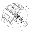
In Fig. 2 ist ein Gerät gezeigt, das erfindungsgemäß mit Sensoren bestückt ist. Es ist dabei eine größere Anzahl von Sensoren dargestellt, was aber nicht bedeutet, daß alle Sensoren immer vorhanden sein müssen. Diese Sensoren sind vielmehr nur der Übersichtlichkeit halber in einer einzigen Zeichnung dargestellt. Die Einzelheiten der mit III bis VIII dargestellten Sensoranordnungen sind in den Fig. 3 bis 8 im größeren Maßstab dargestellt. Entscheidend ist aber die zentrale Elektronikeinheit 30, in der Daten über das Auspreßverhalten von bekannten Komponenten gespeichert sind, die diese gespeicherten Daten mit gemessenen Daten vergleicht, ggf. auch noch Berechnungen zur Berücksichtigung unterschiedlicher Parameter durchführt und dann die Geschwindigkeit des Vorschubmotors und/oder des Mischermotors auf einem günstigen Weg regelt.In Fig. 2, a device is shown, which is equipped according to the invention with sensors. It is shown a larger number of sensors, but this does not mean that all sensors must always be present. Rather, these sensors are only shown in a single drawing for the sake of clarity. The details of the sensor arrangements shown in III to VIII are shown in Figs. 3 to 8 on a larger scale. Decisive, however, is the central
In Fig. 3 ist ein Thermoelement 31 gezeigt, das an der Außenwand der Mischerdüse 10 angebracht ist und dabei die Temperatur der Mehrkomponentenmasse mißt.In Fig. 3, a
In Fig. 4 ist eine Tachoscheibe 32 mit Schlitzen und eine Lichtschranke 33 gezeigt, mit denen die Umdrehungsgeschwindigkeit des Vorschubmotors 15 gemessen werden. Ferner dargestellt ist eine Drehmomentmeßzelle 37 zur Messung des von dem Vorschubmotor 15 aufgebrachten Antriebsmoments.In Fig. 4, a
In Fig. 5 ist ein Dehnungsmeßstreifen 34 gezeigt, der sich radial um die Kartusche 5 erstreckt, um die Verformung der Kartusche in Umfangsrichtung zu messen.In Fig. 5, a
In Fig. 6 ist der Dehnungsstreifen 34 in Axialrichtung angebracht, um in dieser Richtung die Dehnung zu messen.In Fig. 6, the
In Fig. 7 sind Druckmeßzellen 35 dargestellt, die den Druck messen, mit dem die Stempel 11 über die Stempelstangen 12 beaufschlagt werden. Im unteren Teil der Fig. 7 ist dabei eine Ansicht von der Seite parallel zur Ebene der Darstellung des oberen Teils der Fig. 7 gezeigt.In Fig. 7
In Fig. 8 ist schließlich eine Meßzelle 36 dargestellt, mit der das Drehmoment der Mischantriebswelle 23 gemessen wird.In Fig. 8, finally, a measuring
Die Meßsensoren der Fig. 3 bis 8 sind dabei auf nicht gezeigte Weise mit der zentralen Elektronik 30 verbunden, um so Signale über das Auspreßverhalten an die Einheit 30 abzugeben, die dann die Regelung der Antriebsgeschwindigkeiten der Motoren 15 und 22 bewirkt.The measuring sensors of Figs. 3 to 8 are connected in a manner not shown to the
Claims (18)
- Method for generating a multi-component compound, in particular for dental purposes, by pressing its components out from exchangeable cartridges, which are arranged alongside one another and open into a mixer, by jointly advancing their plungers by means of an electric drive, in which measured values of the pressing-out behaviour are determined by sensors and the advance speed is regulated, characterized in that the measured values are compared with corresponding stored or calculated values for known materials, the material is identified on the basis of this comparison, and the advance speed is adjusted to the value suitable for this material.
- Method according to Claim 1, characterized in that the current consumption or the torque of the electric drive for the advance is measured.
- Method according to either of Claims 1 and 2, characterized in that the pressing-out pressure of one or all of the components is measured.
- Method according to either of Claims 2 and 3, characterized in that the advance speed is measured.
- Method according to one of Claims 1 to 4,
characterized in that the deformation of one or all of the cartridges is measured. - Method according to one of Claims 1 to 5,
characterized in that the deformation of the cartridge holder is measured. - Method according to one of Claims 1 to 6,
characterized in that the components are mixed using a mixer driven by an electric motor, and the current consumption or the torque of this electric motor is measured. - Method according to Claim 7, characterized in that the speed of rotation of the electric motor for the mixer is regulated.
- Method according to one of Claims 1 to 8,
characterized in that the temperature of one or all of the components is measured. - Device for generating a multi-component compound, in particular for dental purposes, by pressing out and mixing its components from cartridges (5), which open into a mixer (10) and are arranged in an exchangeable manner in the apparatus which has an electric motor (15) for the joint advance of the plungers assigned to the cartridges (5) and has sensors (III to VIII) for measured values of the pressing-out behaviour, the advance speed being regulated, characterized in that it has storage means (30) for storing the pressing-out behaviour of known materials and the measured values of known materials determined by the sensors (III to VIII), comparing and calculating means (30) for stored and measured values for identification of the material on the basis of the comparison, and regulating means (30) for regulating the advance speed to the value measured for this material.
- Device according to Claim 10, characterized in that it has means for measuring the current consumption or the torque (37) of the electric drive (15) for the advance.
- Device according to either of Claims 10 and 11, characterized in that it has means (34) for measuring the pressing-out pressure of one or all of the components.
- Device according to one of Claims 10 to 12,
characterized in that it has means for measuring the advance speed (32, 33). - Device according to one of Claims 10 to 13,
characterized in that it has means (34) for measuring the deformation of one or all of the cartridges. - Device according to one of Claims 10 to 14,
characterized in that it has means for measuring the deformation of the cartridge holder. - Device according to one of Claims 10 to 15,
characterized in that it has a mixer (10), driven by an electric motor (22), and means for measuring the current consumption or the torque (36) of the electric motor (22). - Device according to one of Claims 10 to 16,
characterized in that it has means (30) for regulating the speed of rotation of the electric motor (22) for the mixer. - Device according to one of Claims 10 to 17,
characterized in that it has temperature measurement means (31).
Priority Applications (3)
| Application Number | Priority Date | Filing Date | Title |
|---|---|---|---|
| DE50110155T DE50110155D1 (en) | 2001-07-26 | 2001-07-26 | Method and device for producing a multicomponent mass |
| EP01118143A EP1279379B9 (en) | 2001-07-26 | 2001-07-26 | Method and device for obtaining a multicomponent mass, especially for dental purposes |
| US10/200,356 US6932237B2 (en) | 2001-07-26 | 2002-07-22 | Method and device for generating a multi-component compound |
Applications Claiming Priority (1)
| Application Number | Priority Date | Filing Date | Title |
|---|---|---|---|
| EP01118143A EP1279379B9 (en) | 2001-07-26 | 2001-07-26 | Method and device for obtaining a multicomponent mass, especially for dental purposes |
Publications (3)
| Publication Number | Publication Date |
|---|---|
| EP1279379A1 EP1279379A1 (en) | 2003-01-29 |
| EP1279379B1 EP1279379B1 (en) | 2006-06-14 |
| EP1279379B9 true EP1279379B9 (en) | 2006-12-13 |
Family
ID=8178146
Family Applications (1)
| Application Number | Title | Priority Date | Filing Date |
|---|---|---|---|
| EP01118143A Expired - Lifetime EP1279379B9 (en) | 2001-07-26 | 2001-07-26 | Method and device for obtaining a multicomponent mass, especially for dental purposes |
Country Status (3)
| Country | Link |
|---|---|
| US (1) | US6932237B2 (en) |
| EP (1) | EP1279379B9 (en) |
| DE (1) | DE50110155D1 (en) |
Cited By (1)
| Publication number | Priority date | Publication date | Assignee | Title |
|---|---|---|---|---|
| CN104010736A (en) * | 2011-12-21 | 2014-08-27 | Sika技术股份公司 | Driving device of a dosing and mixing device |
Families Citing this family (31)
| Publication number | Priority date | Publication date | Assignee | Title |
|---|---|---|---|---|
| EP1599292B1 (en) * | 2003-03-06 | 2007-08-15 | Dentsply International, Inc. | Dispensing and mixing tip |
| EP1570805A1 (en) * | 2004-03-01 | 2005-09-07 | 3M Espe AG | Device and method for generating a multi-component compound |
| EP1657804A1 (en) * | 2004-11-09 | 2006-05-17 | 3M Espe Ag | Method of mixing and extruding viscous materials and gearbox for dispensing the same |
| DE102005033260A1 (en) | 2005-07-15 | 2007-02-08 | Ernst Mühlbauer Gmbh & Co. Kg | Method and device for producing a multicomponent mass |
| DE102005033261B4 (en) | 2005-07-15 | 2018-08-16 | Ernst Mühlbauer Gmbh & Co. Kg | Method and device for producing a multicomponent mass |
| DE202006014187U1 (en) * | 2006-02-24 | 2007-01-18 | Vosschemie Gmbh | Device for mixing binder and hardener in machine for preparing filler, e.g. for automobile bodywork, comprises binder and hardener supply controlled so that small amount of hardener is pre-injected |
| DE202006007425U1 (en) * | 2006-05-10 | 2006-10-12 | Vosschemie Gmbh | Continually operated mixer assembly for semi-liquid crack filling agent has fixed cylinder separated from inner rotor by annular chamber with mixer teeth |
| EP1836992A1 (en) | 2006-03-10 | 2007-09-26 | 3M Innovative Properties Company | Mixing device and drive for the mixing device |
| EP1834603A1 (en) * | 2006-03-10 | 2007-09-19 | 3M Innovative Properties Company | Dispenser and method for dispensing dental material |
| DE102006038897B4 (en) * | 2006-08-18 | 2014-10-16 | Mühlbauer Technology Gmbh | Apparatus for generating a multicomponent mass |
| CH699611B1 (en) * | 2007-05-01 | 2010-04-15 | Sulzer Mixpac Ag | Tabletop device for mixing and dispensing of multicomponent compositions. |
| DK2209561T3 (en) * | 2007-11-12 | 2011-10-24 | Zhermack Spa | Dispensing device for two-component substances |
| WO2009097892A1 (en) * | 2008-02-04 | 2009-08-13 | Coltene Whaledent Ag | Mixing device |
| EP2198949A1 (en) * | 2008-12-18 | 2010-06-23 | Sika Technology AG | Dispensing tool for multi-component substances |
| GB0915008D0 (en) * | 2009-08-28 | 2009-09-30 | 3M Innovative Properties Co | Device for dispensing a dental material |
| DE202010001096U1 (en) * | 2010-01-18 | 2010-04-15 | Renfert Gmbh | Dental device for producing a multicomponent mass |
| DE102011081137B4 (en) * | 2011-08-17 | 2015-03-12 | Henkel Ag & Co. Kgaa | output system |
| EP2606985A1 (en) * | 2011-12-21 | 2013-06-26 | Sika Technology AG | Driving equipment for dosing and mixing apparatus |
| EP2606986A1 (en) * | 2011-12-21 | 2013-06-26 | Sika Technology AG | Driving equipment for dosing and mixing apparatus |
| BR112014016964B1 (en) | 2012-01-12 | 2020-09-01 | Sulzer Mixpac Ag | MOTORIZED DISPENSER OF VISCOSE MATERIAL AND METHOD OF OPERATING A DISPENSER |
| BR112015000149A2 (en) * | 2012-07-03 | 2017-06-27 | 3M Innovative Properties Co | system and device for dispensing dental material and cartridge for use with the system or device |
| US20140036616A1 (en) * | 2012-08-04 | 2014-02-06 | Common Sense, Llc | Dispensing and mixing systems |
| DE102013109265A1 (en) * | 2013-08-27 | 2015-03-05 | Krones Ag | Device and method for emptying containers with control of a drive torque |
| ES2726179T3 (en) * | 2014-03-24 | 2019-10-02 | Sulzer Mixpac Ag | Dispenser |
| GB2530476A (en) * | 2014-07-15 | 2016-03-30 | Cox Ltd | Multicomponent dispenser |
| DE102015104440A1 (en) * | 2015-03-24 | 2016-09-29 | Heraeus Kulzer Gmbh | Process for producing dental prostheses and ready-to-use dental material and kit containing the dental material |
| US10717095B2 (en) * | 2016-02-05 | 2020-07-21 | Bae Systems Plc | End effector for a robot |
| US20190091720A1 (en) * | 2016-03-16 | 2019-03-28 | Henkel Ag & Co. Kgaa | Battery powered dispenser for one and two component foils and cartridges |
| KR101800249B1 (en) * | 2016-12-23 | 2017-12-20 | 주식회사 티앤알바이오팹 | Mixing Device for Cell-printing Composition |
| DE102017112440A1 (en) * | 2017-06-06 | 2018-12-06 | Shin-Etsu Silicones Europe B.V. | Container and dosing device for viscous materials |
| EP3666401A1 (en) * | 2018-12-14 | 2020-06-17 | Hilti Aktiengesellschaft | Pressing system and method for operating a pressing system |
Family Cites Families (12)
| Publication number | Priority date | Publication date | Assignee | Title |
|---|---|---|---|---|
| US4341327A (en) * | 1980-02-28 | 1982-07-27 | Vernon Zeitz | Digital proportional metering pumping system |
| US4493286A (en) * | 1983-07-25 | 1985-01-15 | Koppers Company, Inc. | Method and apparatus for applying a multi-component adhesive |
| DE3705741A1 (en) * | 1987-02-23 | 1988-09-01 | Hilti Ag | DISPENSING DEVICE FOR FLOWABLE MEASURES |
| US5020693A (en) * | 1989-06-30 | 1991-06-04 | Illinois Tool Works Inc. | Dosage control for adhesive dispenser |
| US5605252A (en) * | 1991-03-26 | 1997-02-25 | The United States Of America As Represented By The Secretary Of The Navy | Metering system for compressible fluids |
| US5370273A (en) * | 1991-10-16 | 1994-12-06 | Minnesota Mining And Manufacturing Company | Multi-component applicator assembly |
| US5816445A (en) * | 1996-01-25 | 1998-10-06 | Stainless Steel Coatings, Inc. | Method of and apparatus for controlled dispensing of two-part bonding, casting and similar fluids and the like |
| US5857589A (en) * | 1996-11-20 | 1999-01-12 | Fluid Research Corporation | Method and apparatus for accurately dispensing liquids and solids |
| US6047861A (en) * | 1998-04-15 | 2000-04-11 | Vir Engineering, Inc. | Two component fluid dispenser |
| DE59807131D1 (en) * | 1998-11-11 | 2003-03-13 | Muehlbauer Ernst Gmbh & Co Kg | Method and device for producing a multi-component mass, in particular for dental purposes |
| DE29822967U1 (en) * | 1998-12-23 | 2000-05-11 | Espe Dental Ag | Device for spreading flowable masses |
| DE19951504C2 (en) | 1999-10-26 | 2002-02-21 | 3M Espe Ag | Mixing device and method |
-
2001
- 2001-07-26 EP EP01118143A patent/EP1279379B9/en not_active Expired - Lifetime
- 2001-07-26 DE DE50110155T patent/DE50110155D1/en not_active Expired - Lifetime
-
2002
- 2002-07-22 US US10/200,356 patent/US6932237B2/en not_active Expired - Lifetime
Cited By (2)
| Publication number | Priority date | Publication date | Assignee | Title |
|---|---|---|---|---|
| CN104010736A (en) * | 2011-12-21 | 2014-08-27 | Sika技术股份公司 | Driving device of a dosing and mixing device |
| CN104010736B (en) * | 2011-12-21 | 2016-11-16 | Sika技术股份公司 | Dispensing and the driving means of mixing apparatus |
Also Published As
| Publication number | Publication date |
|---|---|
| DE50110155D1 (en) | 2006-07-27 |
| EP1279379B1 (en) | 2006-06-14 |
| EP1279379A1 (en) | 2003-01-29 |
| US20030022128A1 (en) | 2003-01-30 |
| US6932237B2 (en) | 2005-08-23 |
Similar Documents
| Publication | Publication Date | Title |
|---|---|---|
| EP1279379B1 (en) | Method and device for obtaining a multicomponent mass, especially for dental purposes | |
| EP1010401B1 (en) | Method and device for obtaining a multicomponent mass, especially for dental purposes | |
| EP1929253B1 (en) | Method for controlling a dosing apparatus for liquid or pasty media | |
| DE60129346T2 (en) | Mixing, storage and dispensing device for multiple components | |
| EP2314384B1 (en) | Extruder | |
| DE102010045935B4 (en) | Container, container system, method for applying a pasty mass from this container and method for mixing a plurality of masses from this container | |
| EP2059185B1 (en) | Device for producing a multi-component compound | |
| EP2794120B1 (en) | Driving equipment for dosing and mixing apparatus | |
| EP2744603B1 (en) | Discharging system | |
| EP2794121A1 (en) | Drive device of a metering and mixing device | |
| EP1328238B1 (en) | Device for determining the end of the processing time for hardening dental masses | |
| WO2013092334A1 (en) | Driving device of a metering and mixing apparatus for multi-component substances | |
| DE10335146B4 (en) | Apparatus and method for the metered dispensing of a viscous medium | |
| DE102006043710B4 (en) | Device for dispensing and mixing highly viscous or pasty masses | |
| DE102011075873A1 (en) | Squeeze gun for pressing container by using two separate film cartridges, has pistons, which are connected to drive of feed device via transmission unit, where speed of respective piston is set by transmission units | |
| WO2011006996A1 (en) | Dispensing system for dispensing liquid or viscous materials | |
| WO2010070106A1 (en) | Dispensing tool for multicomponent substances | |
| EP1906863B1 (en) | Method and device for producing a multicomponent compound | |
| EP1575445B9 (en) | Device for dispensing a mixed multi-component compound | |
| EP0589827B1 (en) | Cartridge and bags containing hardenable mortar masses | |
| EP3718501B1 (en) | Dispenser for dental materials | |
| EP1903976B1 (en) | Method and device for producing a multicomponent compound | |
| DE102021103845A1 (en) | Device for providing printing ink and printing unit with such a device | |
| DE2439269C2 (en) | Drug injection device | |
| DE102021103846A1 (en) | Ink supply system for supplying printing ink to an inking unit, printing unit with such an inking unit and method for supplying printing ink to an ink master space of an inking unit |
Legal Events
| Date | Code | Title | Description |
|---|---|---|---|
| PUAI | Public reference made under article 153(3) epc to a published international application that has entered the european phase |
Free format text: ORIGINAL CODE: 0009012 |
|
| AK | Designated contracting states |
Designated state(s): AT BE CH CY DE DK ES FI FR GB GR IE IT LI LU MC NL PT SE TR |
|
| AX | Request for extension of the european patent |
Extension state: AL LT LV MK RO SI |
|
| 17P | Request for examination filed |
Effective date: 20030701 |
|
| AKX | Designation fees paid |
Designated state(s): CH DE LI |
|
| 17Q | First examination report despatched |
Effective date: 20040729 |
|
| GRAP | Despatch of communication of intention to grant a patent |
Free format text: ORIGINAL CODE: EPIDOSNIGR1 |
|
| GRAS | Grant fee paid |
Free format text: ORIGINAL CODE: EPIDOSNIGR3 |
|
| GRAA | (expected) grant |
Free format text: ORIGINAL CODE: 0009210 |
|
| AK | Designated contracting states |
Kind code of ref document: B1 Designated state(s): CH DE LI |
|
| REG | Reference to a national code |
Ref country code: CH Ref legal event code: EP |
|
| REG | Reference to a national code |
Ref country code: CH Ref legal event code: NV Representative=s name: TROESCH SCHEIDEGGER WERNER AG |
|
| REF | Corresponds to: |
Ref document number: 50110155 Country of ref document: DE Date of ref document: 20060727 Kind code of ref document: P |
|
| PLBE | No opposition filed within time limit |
Free format text: ORIGINAL CODE: 0009261 |
|
| STAA | Information on the status of an ep patent application or granted ep patent |
Free format text: STATUS: NO OPPOSITION FILED WITHIN TIME LIMIT |
|
| 26N | No opposition filed |
Effective date: 20070315 |
|
| PGFP | Annual fee paid to national office [announced via postgrant information from national office to epo] |
Ref country code: DE Payment date: 20190920 Year of fee payment: 19 |
|
| PGFP | Annual fee paid to national office [announced via postgrant information from national office to epo] |
Ref country code: CH Payment date: 20190725 Year of fee payment: 19 |
|
| REG | Reference to a national code |
Ref country code: DE Ref legal event code: R119 Ref document number: 50110155 Country of ref document: DE |
|
| REG | Reference to a national code |
Ref country code: CH Ref legal event code: PL |
|
| PG25 | Lapsed in a contracting state [announced via postgrant information from national office to epo] |
Ref country code: LI Free format text: LAPSE BECAUSE OF NON-PAYMENT OF DUE FEES Effective date: 20200731 Ref country code: CH Free format text: LAPSE BECAUSE OF NON-PAYMENT OF DUE FEES Effective date: 20200731 |
|
| PG25 | Lapsed in a contracting state [announced via postgrant information from national office to epo] |
Ref country code: DE Free format text: LAPSE BECAUSE OF NON-PAYMENT OF DUE FEES Effective date: 20210202 |