EP2313270B1 - Employing secondary back exposure of flexographic plate - Google Patents
Employing secondary back exposure of flexographic plate Download PDFInfo
- Publication number
- EP2313270B1 EP2313270B1 EP09788958A EP09788958A EP2313270B1 EP 2313270 B1 EP2313270 B1 EP 2313270B1 EP 09788958 A EP09788958 A EP 09788958A EP 09788958 A EP09788958 A EP 09788958A EP 2313270 B1 EP2313270 B1 EP 2313270B1
- Authority
- EP
- European Patent Office
- Prior art keywords
- mask
- printing plate
- flexographic printing
- plate precursor
- mask image
- Prior art date
- Legal status (The legal status is an assumption and is not a legal conclusion. Google has not performed a legal analysis and makes no representation as to the accuracy of the status listed.)
- Not-in-force
Links
- 239000002243 precursor Substances 0.000 claims description 80
- 230000005855 radiation Effects 0.000 claims description 72
- 239000000463 material Substances 0.000 claims description 68
- 238000000034 method Methods 0.000 claims description 35
- 239000000758 substrate Substances 0.000 claims description 26
- 238000010030 laminating Methods 0.000 claims description 6
- 239000010410 layer Substances 0.000 description 36
- 238000003384 imaging method Methods 0.000 description 32
- 230000008569 process Effects 0.000 description 18
- 238000010586 diagram Methods 0.000 description 14
- 230000007246 mechanism Effects 0.000 description 10
- 239000011230 binding agent Substances 0.000 description 7
- 238000011161 development Methods 0.000 description 7
- -1 polyethylene terephthalate Polymers 0.000 description 7
- 229920000642 polymer Polymers 0.000 description 7
- 239000000178 monomer Substances 0.000 description 6
- 229920005989 resin Polymers 0.000 description 5
- 239000011347 resin Substances 0.000 description 5
- 239000006096 absorbing agent Substances 0.000 description 4
- 239000007789 gas Substances 0.000 description 4
- PLXMOAALOJOTIY-FPTXNFDTSA-N Aesculin Natural products OC[C@@H]1[C@@H](O)[C@H](O)[C@@H](O)[C@H](O)[C@H]1Oc2cc3C=CC(=O)Oc3cc2O PLXMOAALOJOTIY-FPTXNFDTSA-N 0.000 description 3
- 239000011248 coating agent Substances 0.000 description 3
- 238000000576 coating method Methods 0.000 description 3
- 239000003086 colorant Substances 0.000 description 3
- 238000005516 engineering process Methods 0.000 description 3
- 238000002474 experimental method Methods 0.000 description 3
- 230000014759 maintenance of location Effects 0.000 description 3
- 230000003287 optical effect Effects 0.000 description 3
- 238000012545 processing Methods 0.000 description 3
- 238000012546 transfer Methods 0.000 description 3
- 239000000654 additive Substances 0.000 description 2
- 230000005540 biological transmission Effects 0.000 description 2
- 230000015572 biosynthetic process Effects 0.000 description 2
- 150000001875 compounds Chemical class 0.000 description 2
- 239000000945 filler Substances 0.000 description 2
- 238000005286 illumination Methods 0.000 description 2
- 239000003999 initiator Substances 0.000 description 2
- 238000003475 lamination Methods 0.000 description 2
- 238000004519 manufacturing process Methods 0.000 description 2
- QSHDDOUJBYECFT-UHFFFAOYSA-N mercury Chemical compound [Hg] QSHDDOUJBYECFT-UHFFFAOYSA-N 0.000 description 2
- 239000000203 mixture Substances 0.000 description 2
- 239000002985 plastic film Substances 0.000 description 2
- 239000004014 plasticizer Substances 0.000 description 2
- 239000002356 single layer Substances 0.000 description 2
- 239000000126 substance Substances 0.000 description 2
- PYSRRFNXTXNWCD-UHFFFAOYSA-N 3-(2-phenylethenyl)furan-2,5-dione Chemical compound O=C1OC(=O)C(C=CC=2C=CC=CC=2)=C1 PYSRRFNXTXNWCD-UHFFFAOYSA-N 0.000 description 1
- OKTJSMMVPCPJKN-UHFFFAOYSA-N Carbon Chemical compound [C] OKTJSMMVPCPJKN-UHFFFAOYSA-N 0.000 description 1
- 108010010803 Gelatin Proteins 0.000 description 1
- 229920001730 Moisture cure polyurethane Polymers 0.000 description 1
- 239000004698 Polyethylene Substances 0.000 description 1
- 239000004743 Polypropylene Substances 0.000 description 1
- 241000270295 Serpentes Species 0.000 description 1
- 229920000147 Styrene maleic anhydride Polymers 0.000 description 1
- 238000002679 ablation Methods 0.000 description 1
- 239000011358 absorbing material Substances 0.000 description 1
- 229920006397 acrylic thermoplastic Polymers 0.000 description 1
- 230000009471 action Effects 0.000 description 1
- 239000002318 adhesion promoter Substances 0.000 description 1
- 230000001070 adhesive effect Effects 0.000 description 1
- 239000003963 antioxidant agent Substances 0.000 description 1
- 239000003125 aqueous solvent Substances 0.000 description 1
- 238000003491 array Methods 0.000 description 1
- 239000011324 bead Substances 0.000 description 1
- 230000001680 brushing effect Effects 0.000 description 1
- 229910052799 carbon Inorganic materials 0.000 description 1
- 229920002301 cellulose acetate Polymers 0.000 description 1
- 230000008859 change Effects 0.000 description 1
- 229920001577 copolymer Polymers 0.000 description 1
- 239000003431 cross linking reagent Substances 0.000 description 1
- 238000009792 diffusion process Methods 0.000 description 1
- 229920001971 elastomer Polymers 0.000 description 1
- 230000002708 enhancing effect Effects 0.000 description 1
- JEIPFZHSYJVQDO-UHFFFAOYSA-N ferric oxide Chemical compound O=[Fe]O[Fe]=O JEIPFZHSYJVQDO-UHFFFAOYSA-N 0.000 description 1
- 229960005191 ferric oxide Drugs 0.000 description 1
- NBVXSUQYWXRMNV-UHFFFAOYSA-N fluoromethane Chemical compound FC NBVXSUQYWXRMNV-UHFFFAOYSA-N 0.000 description 1
- 229920000159 gelatin Polymers 0.000 description 1
- 239000008273 gelatin Substances 0.000 description 1
- 235000019322 gelatine Nutrition 0.000 description 1
- 235000011852 gelatine desserts Nutrition 0.000 description 1
- 239000001866 hydroxypropyl methyl cellulose Substances 0.000 description 1
- 229920003088 hydroxypropyl methyl cellulose Polymers 0.000 description 1
- 235000010979 hydroxypropyl methyl cellulose Nutrition 0.000 description 1
- UFVKGYZPFZQRLF-UHFFFAOYSA-N hydroxypropyl methyl cellulose Chemical compound OC1C(O)C(OC)OC(CO)C1OC1C(O)C(O)C(OC2C(C(O)C(OC3C(C(O)C(O)C(CO)O3)O)C(CO)O2)O)C(CO)O1 UFVKGYZPFZQRLF-UHFFFAOYSA-N 0.000 description 1
- 239000003112 inhibitor Substances 0.000 description 1
- UQSXHKLRYXJYBZ-UHFFFAOYSA-N iron oxide Inorganic materials [Fe]=O UQSXHKLRYXJYBZ-UHFFFAOYSA-N 0.000 description 1
- 235000013980 iron oxide Nutrition 0.000 description 1
- 238000001459 lithography Methods 0.000 description 1
- 239000006224 matting agent Substances 0.000 description 1
- 229910044991 metal oxide Inorganic materials 0.000 description 1
- 150000004706 metal oxides Chemical class 0.000 description 1
- 229920000609 methyl cellulose Polymers 0.000 description 1
- 239000001923 methylcellulose Substances 0.000 description 1
- 238000001000 micrograph Methods 0.000 description 1
- 239000013307 optical fiber Substances 0.000 description 1
- 239000003960 organic solvent Substances 0.000 description 1
- 238000004806 packaging method and process Methods 0.000 description 1
- 239000002245 particle Substances 0.000 description 1
- 239000011236 particulate material Substances 0.000 description 1
- 239000000049 pigment Substances 0.000 description 1
- 229920003207 poly(ethylene-2,6-naphthalate) Polymers 0.000 description 1
- 229920003229 poly(methyl methacrylate) Polymers 0.000 description 1
- 229920002037 poly(vinyl butyral) polymer Polymers 0.000 description 1
- 229920000728 polyester Polymers 0.000 description 1
- 229920000573 polyethylene Polymers 0.000 description 1
- 239000011112 polyethylene naphthalate Substances 0.000 description 1
- 229920000139 polyethylene terephthalate Polymers 0.000 description 1
- 239000005020 polyethylene terephthalate Substances 0.000 description 1
- 238000006116 polymerization reaction Methods 0.000 description 1
- 229920001155 polypropylene Polymers 0.000 description 1
- 229920002451 polyvinyl alcohol Polymers 0.000 description 1
- 229920000915 polyvinyl chloride Polymers 0.000 description 1
- 239000004800 polyvinyl chloride Substances 0.000 description 1
- 230000001141 propulsive effect Effects 0.000 description 1
- 239000006254 rheological additive Substances 0.000 description 1
- 230000003678 scratch resistant effect Effects 0.000 description 1
- 238000005201 scrubbing Methods 0.000 description 1
- 230000035945 sensitivity Effects 0.000 description 1
- 239000002904 solvent Substances 0.000 description 1
- 238000000859 sublimation Methods 0.000 description 1
- 230000008022 sublimation Effects 0.000 description 1
- ISXSCDLOGDJUNJ-UHFFFAOYSA-N tert-butyl prop-2-enoate Chemical compound CC(C)(C)OC(=O)C=C ISXSCDLOGDJUNJ-UHFFFAOYSA-N 0.000 description 1
- 238000012719 thermal polymerization Methods 0.000 description 1
- 230000009466 transformation Effects 0.000 description 1
- 238000005406 washing Methods 0.000 description 1
Images


Classifications
-
- G—PHYSICS
- G03—PHOTOGRAPHY; CINEMATOGRAPHY; ANALOGOUS TECHNIQUES USING WAVES OTHER THAN OPTICAL WAVES; ELECTROGRAPHY; HOLOGRAPHY
- G03F—PHOTOMECHANICAL PRODUCTION OF TEXTURED OR PATTERNED SURFACES, e.g. FOR PRINTING, FOR PROCESSING OF SEMICONDUCTOR DEVICES; MATERIALS THEREFOR; ORIGINALS THEREFOR; APPARATUS SPECIALLY ADAPTED THEREFOR
- G03F7/00—Photomechanical, e.g. photolithographic, production of textured or patterned surfaces, e.g. printing surfaces; Materials therefor, e.g. comprising photoresists; Apparatus specially adapted therefor
- G03F7/20—Exposure; Apparatus therefor
- G03F7/2002—Exposure; Apparatus therefor with visible light or UV light, through an original having an opaque pattern on a transparent support, e.g. film printing, projection printing; by reflection of visible or UV light from an original such as a printed image
- G03F7/2014—Contact or film exposure of light sensitive plates such as lithographic plates or circuit boards, e.g. in a vacuum frame
- G03F7/2016—Contact mask being integral part of the photosensitive element and subject to destructive removal during post-exposure processing
- G03F7/202—Masking pattern being obtained by thermal means, e.g. laser ablation
-
- G—PHYSICS
- G03—PHOTOGRAPHY; CINEMATOGRAPHY; ANALOGOUS TECHNIQUES USING WAVES OTHER THAN OPTICAL WAVES; ELECTROGRAPHY; HOLOGRAPHY
- G03F—PHOTOMECHANICAL PRODUCTION OF TEXTURED OR PATTERNED SURFACES, e.g. FOR PRINTING, FOR PROCESSING OF SEMICONDUCTOR DEVICES; MATERIALS THEREFOR; ORIGINALS THEREFOR; APPARATUS SPECIALLY ADAPTED THEREFOR
- G03F7/00—Photomechanical, e.g. photolithographic, production of textured or patterned surfaces, e.g. printing surfaces; Materials therefor, e.g. comprising photoresists; Apparatus specially adapted therefor
- G03F7/20—Exposure; Apparatus therefor
- G03F7/2022—Multi-step exposure, e.g. hybrid; backside exposure; blanket exposure, e.g. for image reversal; edge exposure, e.g. for edge bead removal; corrective exposure
- G03F7/203—Multi-step exposure, e.g. hybrid; backside exposure; blanket exposure, e.g. for image reversal; edge exposure, e.g. for edge bead removal; corrective exposure comprising an imagewise exposure to electromagnetic radiation or corpuscular radiation
-
- G—PHYSICS
- G03—PHOTOGRAPHY; CINEMATOGRAPHY; ANALOGOUS TECHNIQUES USING WAVES OTHER THAN OPTICAL WAVES; ELECTROGRAPHY; HOLOGRAPHY
- G03F—PHOTOMECHANICAL PRODUCTION OF TEXTURED OR PATTERNED SURFACES, e.g. FOR PRINTING, FOR PROCESSING OF SEMICONDUCTOR DEVICES; MATERIALS THEREFOR; ORIGINALS THEREFOR; APPARATUS SPECIALLY ADAPTED THEREFOR
- G03F7/00—Photomechanical, e.g. photolithographic, production of textured or patterned surfaces, e.g. printing surfaces; Materials therefor, e.g. comprising photoresists; Apparatus specially adapted therefor
- G03F7/20—Exposure; Apparatus therefor
- G03F7/2051—Exposure without an original mask, e.g. using a programmed deflection of a point source, by scanning, by drawing with a light beam, using an addressed light or corpuscular source
- G03F7/2057—Exposure without an original mask, e.g. using a programmed deflection of a point source, by scanning, by drawing with a light beam, using an addressed light or corpuscular source using an addressed light valve, e.g. a liquid crystal device
-
- G—PHYSICS
- G03—PHOTOGRAPHY; CINEMATOGRAPHY; ANALOGOUS TECHNIQUES USING WAVES OTHER THAN OPTICAL WAVES; ELECTROGRAPHY; HOLOGRAPHY
- G03F—PHOTOMECHANICAL PRODUCTION OF TEXTURED OR PATTERNED SURFACES, e.g. FOR PRINTING, FOR PROCESSING OF SEMICONDUCTOR DEVICES; MATERIALS THEREFOR; ORIGINALS THEREFOR; APPARATUS SPECIALLY ADAPTED THEREFOR
- G03F7/00—Photomechanical, e.g. photolithographic, production of textured or patterned surfaces, e.g. printing surfaces; Materials therefor, e.g. comprising photoresists; Apparatus specially adapted therefor
- G03F7/20—Exposure; Apparatus therefor
- G03F7/2022—Multi-step exposure, e.g. hybrid; backside exposure; blanket exposure, e.g. for image reversal; edge exposure, e.g. for edge bead removal; corrective exposure
Definitions
- Embodiments relate generally to a system and method of forming a relief image on a flexographic printing plate and more particularly to a system and method employing secondary back exposure of a flexographic printing plate precursor.
- Flexographic printing is a method of direct rotary printing that uses a resilient relief image in a plate of rubber or photopolymer (i.e. a flexographic printing plate) to print articles such as cartons, bags, labels or books. Flexographic printing has found particular application in packaging, where it has displaced rotogravure and offset lithography printing techniques in many cases. While the quality of articles printed using flexographic plates has improved significantly as the technology has matured, physical limitations related to the process of creating a relief image in the flexographic printing plate remain.
- EP 0 295 818 A2 discloses a process for preparing a relief printing plate.
- One embodiment provides a method of making a relief image on a flexographic print plate including imagewise exposing a mask including an imageable material disposed on a mask substrate to form an imaged mask having a mask image in the imageable material disposed on the mask substrate, the mask image including mask image areas each having a highlight value.
- the method further includes laminating the imaged mask to a front surface of a flexographic printing plate precursor, and exposing selected areas of the flexographic printing plate precursor to an imagewise addressable curing radiation via a back surface of the flexographic printing plate precursor based on the highlight values of corresponding mask image areas of the mask image, wherein the back surface exposure is carried out based on stored digital data representative of the mask image.
- One embodiment provides a system for forming a relief image on a flexographic print plate including a laminator, a main exposure unit, and a secondary exposure unit.
- the laminator is configured to laminate an imaged mask having a mask image to a front surface of a flexographic printing plate precursor, the mask image having mask image areas each having a highlight value.
- the main exposure unit is configured to expose the flexographic printing plate precursor to curing radiation through the imaged mask
- the secondary exposure unit is configured to expose selected areas of the flexographic printing plate precursor to curing radiation via a back surface of the flexographic printing plate precursor based on highlight values of corresponding mask image areas of the mask image.
- One embodiment provides a method of forming a relief image on a flexographic print plate including laminating an imaged mask having a mask image to a front surface of a flexographic printing plate precursor, the mask image having mask image areas each having a highlight value, and exposing selected areas of the flexographic printing plate precursor to an imagewise addressable curing radiation via a back surface of the flexographic printing plate precursor based on highlight values of corresponding mask image area of the mask image.
- Figure 1 is a block diagram generally illustrating one embodiment of a system 30 for making an article bearing a relief image, such as a flexographic printing plate, from a flexographic printing plate precursor 32.
- system 30 includes a rotating imaging drum 34, a laser unit 36, a main exposure unit 38, a secondary back exposure unit 40, a contact idler roller 42, and a transport bed 44.
- main and secondary back exposure units 38 and 40 are respectively positioned proximate to a front surface 33a and a back surface 33b of flexographic printing plate precursor 32.
- imaging drum 34 receives and secures an imageable mask 50 against an outside surface 46 (e.g. via a vacuum-hold system).
- imaging drum 34 is driven to rotate in a direction as indicated by rotational arrow 48 (e.g. counter clockwise in Figure 1 )
- mask 50 moves along outside surface 46 and past laser unit 36 until merging with flexographic printing plate precursor 32 at a nip 52 formed by imaging drum 34 and contact idler roller 42.
- flexographic printing plate precursor 32 a layer having adhesive properties so that mask 50 is adhesively laminated to flexographic printing plate precursor 32 as they simultaneously pass through nip 52.
- continued rotation of imaging drum 34 moves the laminated combination of flexographic printing plate precursor 32 and mask 50 along transport bed 44 past secondary back exposure unit 40 and main exposure unit 38, as indicated by directional arrow 54.
- laser unit 36 main exposure unit 38, and secondary back exposure unit 40 with respect to mask 50 for the formation of a relief image on flexographic printing plate precursor 32 is described in greater detail below.
- mask 50 comprises an imageable film including at least a mask substrate 60 and an imageable material 62 which comprises a relatively uniform coating of one or more layers disposes on substrate 60.
- mask 50 includes a subbing layer 64 disposed on mask substrate 60 and imageable material 62 disposed on subbing layer 64.
- mask 50 includes an ablatable layer 66 disposed on substrate 60 and imageable material 62 disposed on ablatable layer 66.
- mask 50 includes subbing layer 64 disposed on mask substrate 60, ablatable layer 66 disposed on subbing layer 64, and imageable material 62 disposed on ablatable layer 66.
- laser unit 36 imagewise exposes mask 50 to laser radiation from a laser, such as a laser beam 56, which is focused to impinge on imageable material 62.
- Laser beam 56 is scanned or rasterized under computer control over mask 50 while the output of laser beam 56 is modulated in accordance with electronically stored data representative of a desired image to produce exposed areas 70 and unexposed areas 72 in imageable material 62 of mask 50.
- the radiation is absorbed by an energy absorber in imageable material 62, and in ablatable layer 66 if included in mask 50, and causes transfer of imageable material 62 from mask substrate 60 in areas 70 exposed to the imaging radiation.
- imaging radiation such as laser beam 56
- the radiation is absorbed by an energy absorber in imageable material 62, and in ablatable layer 66 if included in mask 50, and causes transfer of imageable material 62 from mask substrate 60 in areas 70 exposed to the imaging radiation.
- imageable material 62 and other layers remaining on mask substrate 60 together form what is referred to as a "mask image".
- the combination of the mask image and mask substrate 60 is referred to as the imaged mask.
- a process of forming a mask image is also described in U.S. Patent Application Serial No. 11/081,018 .
- Mask substrate 60 may be of any suitable substrate which includes, for example, plastic sheets and films, such as polyethylene terephthalate or polyethylene naphthalate, fluorence polyester polymers, polyethylene, polypropylene, acrylics, polyvinyl chloride and copolymers thereof, and hydrolyzed and non-hydrolized cellulose acetate.
- Mask substrate 60 should be sufficiently transparent to a curing radiation (as will be described below), and in some instances, it may be desirable that mask substrate 60 be sufficiently transparent to imaging radiation, such as laser beam 56.
- Mask substrate 60 may also include an anti-static coating.
- Imageable material 62 includes multiple components such as, for example, a colorant (e.g. a dye or pigment) and an energy absorber dispersed in a binder.
- Imageable material 62 may be disposed as a single layer or multiple layers.
- imageable material 62 may be combined with an ablative material and an absorbing material in a single layer.
- imageable material 62 may include an energy absorbing layer, and a layer comprising ablative material adjacent to the energy absorbing layer.
- imageable material 62 may include other components such as binders for dispersing other components, fluorocarbon additives for enhancing transfer of molten or softened imageable material, suitable latent crosslinking agents, plasticizers, coating agents, UV absorbers, and fillers.
- Subbing layer 64 also known as an adhesion promoter, or a scratch resistant hardcoat or hardened gelatin layer, provides optical contact after lamination (as described in greater detail below) and assists in removing the mask image from photosensitive material of flexographic plate 32 in areas of mask 50 where imageable material 62 was removed during imaging, such as by laser beam 56.
- Ablatable layer 66 may comprise a particulate material, such as metal-oxide particles or iron-oxide particulate, which decompose to provide propulsive gases particularly advantageous for an ablative imaging mechanism.
- the imaging radiation may include infrared radiation.
- the infrared radiation may be, for example in the range of 750-1200 nm and be provided, for example, by an infrared laser such as a diode laser (830 nm) or a Nd:YAG laser (1064 nm).
- imaging material 62 includes an energy absorber that is sensitive to infrared radiation and which converts infrared radiation to heat which may then result in a physical or chemical change is a physical or chemical property.
- imageable material 62 is exposed to visible laser light such as in the range of 400-700 nm, for example.
- imageable material 62 is exposed to UV radiation by laser direct imaging (LDI).
- LIDI laser direct imaging
- exposed areas 70 of imaging material 62 of mask 50 are removed through ablation.
- exposed areas 70 of imaging material 62 (and of ablatable layer 66, if present) are propelled from mask substrate 60 by generation of a gas.
- specific binders that decompose upon exposure to heat (e.g. laser radiation) to rapidly generate a gas may be used in imageable material 62 or in ablatable layer 66.
- the build-up of gas under or within exposed areas 70 of imageable material 62 creates pressure that propels imageable material 62 off of mask substrate 60 in exposed areas 70.
- a layer of imageable material having a colorant, an infrared absorbing dye, and a binder is imaged, wherein energy from the laser drives off the imageable material at the spot where the laser beam impinges the imageable material.
- a debris collector such as a vacuum or suitable receptor sheet, for example, may be placed near the imageable material to retrieve or collect the exposed imageable material after it is propelled from the mask substrate.
- imaging mechanisms may be also be suitable to imagewise expose imaging material 62 of mask 50 including, for example, laser-induced film transfer, a peel-apart mechanism, and dye sublimation or diffusion. These imaging mechanisms, along with ablating mechanisms, are described in greater detail by previously incorporated U.S. Patent No. 7,279,254 to Zwadlo .
- exposed areas 70 are of different sizes or areas.
- exposed areas 70 at the right-hand side of mask 50 are of a smaller size than exposed areas 70 at the left-hand side of mask 50.
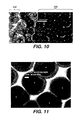
- Figure 4 is a top view of an example portion of mask 50 after being imagewise exposed by laser unit 36 (e.g. using an ablating mechanism). Again it is noted that exposed areas 70 are of varying sizes.
- curing radiation 39 provided by main exposure unit 38 passes through exposed areas 70 (see Figures 1 and 7 ) which, together with a developing process, create conical-shaped "highlight dots" on a flexographic printing plate 32' formed from flexographic printing plate precursor 32. Together, the highlight dots form a desired relief image on flexographic printing plate 32', wherein the varying sizes of exposed areas 70 create varying sizes of highlight dots in the relief image.
- the density of the image is represented by the total area of highlight dots in a halftone screen representation of a continuous tone image.
- Different sized highlight dots correspond to different tone densities. For example, in an area where no density is desired (0% tone), there are no highlight dots, while highlight dots for a 10% tone will be of a larger size than highlight dots for a 5% tone. Based on this correspondence, the sizes of highlight dots are commonly referred to in terms of the tone values to which they correspond, such as 5% highlight dots or 10% highlight dots, for example.
- the smallest highlight dots may represent 1% highlight dots while the largest highlight dots may represent 10% highlight dots.
- the sizes of exposed areas 70 of mask 50 are also referred to in terms of a tone percentage. This percentage is also sometimes referred to as a highlight value. As known, the smaller the size of the exposed areas 70 of the mask image, the more difficult it is to effectively form the corresponding highlight dot in the relief image of flexographic printing plate 32'.
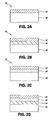
- FIG. 5 is a block diagram illustrating mask 50 after being laminated to flexographic printing plate precursor 32.
- mask 50 is laminated to flexographic printing plate precursor 32 through application of pressure, such as that applied by nip 52.
- mask 50 may be laminated to flexographic printing plate precursor 32 by application on heat. Laminating may also include application of both heat and pressure to flexographic printing plate precursor 32 and mask 50.
- laminators which provide both heat and pressure may be used. Suitable laminators include, for example, KODAK model 880XL APPROVAL LAMINATOR, available from Eastman Kodak Co. (Rochester, N.Y.), and CODOR LPP650 LAMINATOR from COROR laminating systems (Amsterdam, Holland).
- flexographic printing plate precursor 32 includes a photosensitive substrate 80, a photosensitive material 82, and a releasing layer 84, with imaging material 62 of mask 50 being laminated to flexographic printing plate precursor 32 via releasing layer 84.
- flexographic printing plate 32' results from flexographic printing plate precursor 32 after the mask image of mask 50 is formed as a relief image thereon.
- photosensitive material 82 may be either positive working or negative working.
- a negative working photosensitive material hardens or is curable by exposure to a curing radiation and generally includes a polymer or pre-polymer that polymerizes or crosslinks upon exposure to the curing radiation.
- photosensitive material 82 comprises an ultra-violet curable resin which may also include an elastomeric binder, at least one monomer and a photoinitiator, where the initiator has a sensitivity to non-infrared radiation. In most cases, the initiator will be sensitive to ultraviolet or visible radiation or both.
- the elastomeric binder may be a single polymer or a mixture of polymers which may be soluble, swellable or dispersible in aqueous, semi-aqueous or organic solvent developers.
- the monomer may comprise a single monomer or a mixture of monomers which are compatible with the binder to the extent that a clear, non-cloudy photosensitive layer is produced.
- the photoinitiator may be any single compound or combination of compounds which is sensitive to ultraviolet radiation, generating free radicals which initiate the polymerization of the monomer or monomers without excessive termination.
- the photoinitiator should be sensitive to visible or ultraviolet radiation, and may also be insensitive to infrared and/or visible radiation and should be thermally inactive at and below 185° C.
- the ultraviolet curable resin may contain other additives depending on the final properties desired, such as sensitizers, plasticizers, rheology modifiers, thermal polymerization inhibitors, tackifiers, colorants, antioxidants, antiozonants, or fillers, for example.
- a thickness of photosensitive material 82 may vary depending upon the desired type of flexographic printing plate 32.
- the ultraviolet curable resin may be, for example, from 20-250 mils (500-600 microns) or greater in thickness and, more particularly, from 20-100 mils (500-2500 microns) in thickness.
- flexographic printing plate 32 comprises a flexographic printing plate precursor commercially available as FLEXCEL NX from Kodak Polychrome Graphics (Norwalk, CT).
- flexographic printing plate 32 comprises a flexographic printing plate precursor commercially available as FLEXCEL SRH from Kodak Polychrome Graphics (Norwalk, CT)
- Releasing layer 84 facilitates the removal of imaged mask 50 from photosensitive material 82 subsequent to a curing process.
- Releasing material 84 may also provide sufficient adhesion between printing plate 32 and imaged mask 50 during the curing process.
- the releasing layer should not significantly absorb or scatter curing radiation and at room temperatures should allow intact removal of mask 50, but not at high temperatures.
- Releasing layer 84 may also protect the ultraviolet-curable resin of photosensitive material 82 from fingerprinting or other damage.
- coatings suitable for use as releasing layer 84 include poly(vinyl alcohol) or similar polymers, a cellulosic polymer such as methylcellulose or hydroxypropyl methylcellulose, or polyvinyl butyral or other hydroxylic polymer as described above.
- releasing layer 84 is a hydrolyzed styrene maleic anhydride copolymer.
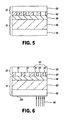
- flexographic printing plate precursor 32 after mask 50 is laminated to front surface 33a of flexographic printing plate precursor 32, continued rotation of imaging drum 34 moves the laminated combination along transport bed 44 first past secondary back exposure unit 40 and then past main exposure unit 38.
- secondary back exposure unit 40 selectively exposes selected areas or regions of photosensitive substrate 80 of flexographic printing plate precursor 32 to a curing radiation 90 via back surface 33b.
- curing radiation 90 comprises ultraviolet radiation.
- back surface 33b of flexographic printing plate precursor 32 is first exposed to a curing radiation via photosensitive substrate 80 so as to prepare a thin, uniform cured layer in photosensitive material 82 adjacent to photosensitive substrate 80, a process commonly referred to as "back-exposure.”
- this thin, uniform cured layer is sometimes referred to as a "floor" of the relief image in photosensitive material 82 of the resulting flexographic printing plate (see Figure 9 ).
- curing radiation 90 provided by secondary back exposure unit 40 increases a thickness of the cured layer of photosensitive material layer 82 in the selected regions (i.e. raises the floor or reduces the relief of the resulting relief image in the selected regions).
- the selected regions exposed by secondary back exposure unit 40 correspond to areas of the mask image of mask 50 where exposed areas 70 have a highlight value at or below a highlight value threshold.
- backside exposure unit 40 is indexed to imaged mask 50 and, based on the electronically stored data employed to produce exposed areas 70 and unexposed areas 72 in the formation of the mask image, secondary back exposure unit 40 exposes those areas having a highlight value at or below the highlight threshold value to curing radiation 90.
- secondary back exposure unit 40 provides exposure radiation where image features (e.g. exposed areas 70) have a highlight value at or below 2%.
- image features e.g. exposed areas 70
- a highlight threshold value e.g. 2%
- the highlight threshold value may vary based on the specific requirements of a given flexographic printing plate precursor.
- curing radiation 90 provided by secondary back exposure unit 40 is digitally controlled so as to expose only the selected regions of flexographic printing plate precursor 32.
- secondary back exposure unit 40 provides imagewise addressable curing radiation 90 via back surface 33b to expose selected region of flexographic printing plate precursor 32 based on highlight values of corresponding mask image areas of the mask image.
- secondary back exposure unit 40 provides imagewise addressable curing radiation 90 via a plurality of individually addressable radiation sources.
- backside exposure unit 40 comprises an array of individually addressable ultraviolet (UV) light emitting diodes (LEDs).
- UV LEDs are arranged to form a linear array which is positioned to extend in a transverse direction across a width of flexographic printing plate precursor 32.
- Examples of commercially available linear UV LED arrays suitable for use as backside exposure unit 40 include UV LED Cure-All Linear 100 available from CON-TROL-CURE.com, COBRA Linescan Illumination devices available from Stockeryale, Inc., and illumination devices from Opto Technology (Wheeling, IL).
- resolution and collimation of the LED array is such that exposure radiation provided by the LEDs is confined to a limited area, such as 100 spots per 2.54 cm (100 spots per inch), for example.
- secondary back exposure unit 40 may comprise any suitable type of digitally addressable light sources such as, for example, a digital light projector(DLP) having an array of individually addressable micro mirrors and an array of optical fibers coupled to individually addressable/controllable light sources.
- DLP digital light projector
- the laminated combination of flexographic printing plate precursor 32 and mask 50 is driven past main exposure unit 38, where, as illustrated by Figure 7 , main exposure unit 38 projects curing radiation 39 in a flood-wise fashion onto photosensitive material 82 of flexographic printing plate precursor 32 through mask 50. Curing radiation 39 is blocked by unexposed areas 72 of mask 50 and passes through exposed or unmasked areas 70 so as to impinge upon photosensitive material 82 to cause hardening or curing.
- the mask image should be substantially opaque to curing radiation 39, wherein substantially opaque means that the mask image should have a transmission optical density of 2.0 or greater, and more particularly 3.0 or greater.
- the unmasked or exposed areas 70 of imageable material 62 and mask substrate 60 should be substantially transparent, wherein substantially transparent means a transmission optical density of 0.5 or less, and more particularly 0.1 or less, even more particularly 0.05 or less in the wavelength of curing radiation 39.
- curing radiation 39 comprises ultraviolet radiation.
- Sources of radiation for flood-wise exposure to ultraviolet radiation are conventional.
- suitable visible or UV sources include carbon arcs, mercury vapor arcs, fluorescent lamps, electron flash units, and photographic flood lamps.
- Suitable sources of LV radiation include mercury-vapor lamps, particularly sun lamps.
- suitable standard radiation sources for main exposure unit 38 include the SYLVANIA 350 BLACKLIGHT fluorescent lamp and the BURGESS EXPOSURE FRAME, Model 5K-3343VSII with ADDALUX 754-18017 lamp, available from Burgess Industries, Inc. (Plymouth, MN).
- the time for exposure through mask 50 depends upon the nature and thickness of photosensitive material 82 of flexographic printing plate precursor 32.
- vacuum draw-down is not required for either the exposure of back surface 33b by secondary back exposure unit 40 or exposure of photosensitive material 82 via mask 50 by curing radiation 39 from main exposure unit 38.
- time required to create a vacuum is not required, and matting agents or beads, which can cause scattering of curing radiation, are not required to be part of mask 50.
- mask 50 is removed from front surface 33a of flexographic printing plate precursor 32 so that imaged mask 50 can be reused.
- Removing mask 50 may be done, for example, by peeling mask 50 from flexographic printing plate precursor 32.
- Removing mask 50 may be done manually or mechanically.
- unhardened or uncured (i.e. non-exposed to curing radiation) portions of photosensitive material 82 of flexographic printing plate precursor 32 are removed by a developing process, leaving the cured portions of photosensitive material 82 which define the relief image or relief printing surface and thereby complete a transformation of flexographic print plate precursor 32 to flexographic print plate 32'.
- the developing process includes washing flexographic printing plate precursor 32 with a suitable developer. Suitable developers may dissolve, disperse, or swell unexposed area of photosensitive material 82.
- Mechanical development may also be suitable and include scrubbing or brushing flexographic printing plate precursor 32 to remove uncured or unhardened portions of photosensitive material 82. Mechanical developing means may also be used in combination with solvent developing means.
- Figure 9 illustrates flexographic printing plate 32' resulting from development of flexographic printing plate precursor 32.
- releasing layer 84 and uncured portions of photosensitive material 82 have been washed away, leaving the cured portions of photosensitive material 82 which correspond to exposed regions 70 of mask 50 and define the desired relief image on photosensitive substrate 80.
- the conical-shaped cured portions of photosensitive material 82 remaining after development are commonly referred to as highlight dots, illustrated as highlight dots 94, 96, 98, 100 and 102.
- highlight dots 94, 96, and 98 correspond to area 92 of mask 50 where the exposed or unmasked areas 70 have a highlight value at or below a given highlight threshold value, such, as 2%, for instance, while highlight dots 100 and 102 correspond exposed areas 70 of mask 50 having a highlight value above the given highlight threshold value.
- a given highlight threshold value such as 2%, for instance
- highlight dots 100 and 102 correspond exposed areas 70 of mask 50 having a highlight value above the given highlight threshold value.
- the floor of the relief image in selected area 92 has a depth 104 which is greater than a "standard" floor depth 106 in non-selected areas (where the "standard" floor was formed exposing the entire back surface 33b to a pre-back exposure radiation).
- a relief depth 108 of highlight dots at or below the given highlight threshold value such as highlight dots 94, 96, and 98, is less than a relief depth 110 of highlight dots above the given highlight threshold value.
- additional floor structure is provided for such highlight dots.
- This additional floor structure provides added stability and enables such highlight dots to better survive the development process (e.g. less likely to be washed off during development) and enables a flexographic printing plate 32' resulting therefrom to retain highlight dots of a smaller size as compared to flexographic printing plates formed according to conventional processes.
- the additional support also helps to better maintain the physical integrity of such highlight dots during subsequent printing processes in which the flexographic printing plate 32' will be employed.
- a Flexel NX mask was imagewise exposed and laminated to a Flexel SRH printing plate precursor (both available from Kodak Polychrome Graphics, Norwalk, CT) having a plate thickness of 1.7mm (0.067 inches).
- a front or main exposure e.g. such as by main exposure unit 38
- highlight dot retention was 2% (with a relative relief of approximately 80 microns) at 133 line screen for a 0.68 mm (27 mil) plate relief.
- a 17mm Flexel SRH flexographic printing plate precursor was back exposed for 11 seconds (for a nominal relief of 0.68 mm (27 mils)).
- An Optotek P 150-3072 UV LED Printhead providing 40mW total output power and having a measured output wavelength of 375 was then employed to additionally back expose a 12.7mm (0.5 inch) wide swath at 1.6 mm/sec to provide a total relief of 0.3 mm (12 mils).
- a 4 minute conventional front exposure i.e. main exposure
- TIL masks with a variety of highlight dot sizes and a 500 micron RLD feature.
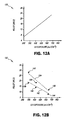
- Figure 12A is a graph 130 illustrating the relief resulting only from back exposure provided by the LED printhead.
- Figure 12B is a graph 132 illustrating the total relief resulting from a combination of conventional pre-back UV exposure and the additional back exposure provided by the LED printhead.
- a first curve 134 illustrates the relief resulting from back exposure provided only by the LED printhead, with data points 136, 138, and 140 corresponding to the increasing speeds at which the LED printhead scanned the photopolymer.
- a second curve 142 illustrates the relief resulting from the UV exposure provided by the LED printhead being combined with the conventional UV back exposure provided by the Mekrom fluorescent light bank unit, with data points 144, 146, and 148 corresponding to the increasing speeds at which the LED printhead scanned the photopolymer.
- Figure 13 illustrates an alternate system 150 for selectively back exposing backside surface 33b of flexographic printing plate precursor 32 using backside exposure unit 40.
- second back exposure unit 40 is instead moved and scanned across backside surface33b of flexographic printing plate precursor 32, such as in the x- and y-directions.
- backside exposure unit 40 is indexed to mask 50, such as via a registration starting point 152.
- registration start point 152 is written into mask 50 and read by secondary back exposure unit 40 for accurate alignment of curing radiation 90 from secondary back exposure unit 40 with mask information.
- system 30 by selectively back-exposing those areas of flexographic printing plate precursor 32 corresponding to exposed regions 70 of mask 50 which are at or below a given highlight value to radiation from backside exposure unit 40, system 30 is able to provide a resulting flexographic printing plate 32' which retains highlight dots of a smaller size (which might otherwise be washed off during development) as compared to conventional processes.
- the secondary selective back exposure provided by backside exposure unit 40 also reduces the exposure time required for the main or main exposure unit 38. For example, using only front exposure via main exposure unit 38, an exposure time of up to 30 minutes may be required, with an added disadvantage that some areas of the mask image may be over-exposed and result in areas of the developed mask having greater than intended highlight values. For example, in one instance, as described above, with a 20 second selected back exposure of flexographic print plate precursor 32 according to the present disclosure, an exposure time of only 8 minutes was required by main exposure unit 38.
Landscapes
- Physics & Mathematics (AREA)
- General Physics & Mathematics (AREA)
- Electromagnetism (AREA)
- Optics & Photonics (AREA)
- Manufacture Or Reproduction Of Printing Formes (AREA)
- Photosensitive Polymer And Photoresist Processing (AREA)
- Exposure And Positioning Against Photoresist Photosensitive Materials (AREA)
Applications Claiming Priority (2)
| Application Number | Priority Date | Filing Date | Title |
|---|---|---|---|
| US12/183,173 US8034540B2 (en) | 2008-07-31 | 2008-07-31 | System and method employing secondary back exposure of flexographic plate |
| PCT/US2009/004203 WO2010014156A1 (en) | 2008-07-31 | 2009-07-21 | Employing secondary back exposure of flexographic plate |
Publications (2)
| Publication Number | Publication Date |
|---|---|
| EP2313270A1 EP2313270A1 (en) | 2011-04-27 |
| EP2313270B1 true EP2313270B1 (en) | 2013-01-23 |
Family
ID=41136710
Family Applications (1)
| Application Number | Title | Priority Date | Filing Date |
|---|---|---|---|
| EP09788958A Not-in-force EP2313270B1 (en) | 2008-07-31 | 2009-07-21 | Employing secondary back exposure of flexographic plate |
Country Status (5)
| Country | Link |
|---|---|
| US (2) | US8034540B2 (enExample) |
| EP (1) | EP2313270B1 (enExample) |
| JP (1) | JP5443484B2 (enExample) |
| CN (1) | CN102112312A (enExample) |
| WO (1) | WO2010014156A1 (enExample) |
Cited By (12)
| Publication number | Priority date | Publication date | Assignee | Title |
|---|---|---|---|---|
| US20150030984A1 (en) * | 2013-07-26 | 2015-01-29 | Uni-Pixel Displays, Inc. | Method of manufacturing a flexographic printing plate for high-resolution printing |
| US9223201B2 (en) | 2013-06-27 | 2015-12-29 | Uni-Pixel Displays, Inc. | Method of manufacturing a photomask with flexography |
| WO2019110809A1 (de) | 2017-12-08 | 2019-06-13 | Flint Group Germany Gmbh | Verfahren zur kennzeichnung eines reliefvorläufers zur herstellung einer reliefstruktur |
| EP3368949B1 (en) | 2015-10-26 | 2022-02-16 | Esko-Graphics Imaging GmbH | System and method for controlled exposure of flexographic printing plates |
| WO2022238296A1 (en) | 2021-05-12 | 2022-11-17 | Flint Group Germany Gmbh | A relief precursor with vegetable oils as plasticizers suitable for printing plates |
| WO2022238298A1 (en) | 2021-05-12 | 2022-11-17 | Flint Group Germany Gmbh | Flexographic printing element precursor with high melt flow index |
| WO2023194387A1 (en) | 2022-04-08 | 2023-10-12 | Xsys Prepress Nv | Method for imaging a mask layer and associated imaging system |
| NL2031806B1 (en) | 2022-05-09 | 2023-11-16 | Xsys Prepress N V | Method, control module and system for imaging a mask layer |
| US12055856B2 (en) | 2015-10-26 | 2024-08-06 | Esko-Graphics Imaging Gmbh | Method and apparatus for exposure of flexographic printing plates using light emitting diode (LED) radiation sources |
| EP4488756A2 (en) | 2023-07-06 | 2025-01-08 | XSYS Germany GmbH | Relief precursors with enhanced stability |
| WO2025247890A1 (en) | 2024-05-27 | 2025-12-04 | Xsys Germany Gmbh | Printing plate precursor |
| NL2038022B1 (en) | 2024-06-21 | 2026-01-15 | Xsys Germany Gmbh | Printing plate precursor |
Families Citing this family (33)
| Publication number | Priority date | Publication date | Assignee | Title |
|---|---|---|---|---|
| TWI504935B (zh) * | 2010-01-22 | 2015-10-21 | Lg Chemical Ltd | 光學濾光片以及含有此光學濾光片的立體影像顯示裝置 |
| DE102010031527A1 (de) * | 2010-07-19 | 2012-01-19 | Flint Group Germany Gmbh | Verfahren zur Herstellung von Flexodruckformen umfassend die Bestrahlung mit UV-LEDs |
| EP2466381B1 (en) * | 2010-12-16 | 2021-05-19 | Xeikon Prepress N.V. | A processing apparatus for processing a flexographic plate, a method and a computer program product |
| US20120210893A1 (en) * | 2011-02-21 | 2012-08-23 | Tutt Lee W | Floor relief for dot improvement |
| US8520041B2 (en) * | 2011-02-21 | 2013-08-27 | Eastman Kodak Company | Floor relief for dot improvement |
| WO2012115888A1 (en) * | 2011-02-21 | 2012-08-30 | Eastman Kodak Company | Floor relief for dot improvement |
| US8599232B2 (en) * | 2011-09-21 | 2013-12-03 | Eastman Kodak Company | Integral cushion for flexographic printing plates |
| KR101924309B1 (ko) * | 2011-12-20 | 2018-11-30 | 가부시키가이샤 니콘 | 기판 처리 장치, 디바이스 제조 시스템 및 디바이스 제조 방법 |
| TWI575330B (zh) * | 2012-03-27 | 2017-03-21 | 尼康股份有限公司 | 光罩搬送裝置、光罩保持裝置、基板處理裝置、及元件製造方法 |
| JP6013599B2 (ja) | 2012-06-11 | 2016-10-25 | イーストマン コダック カンパニー | 基板をフレキソ印刷する方法及び基板をフレキソ印刷するためのシステム |
| US20130337386A1 (en) * | 2012-06-14 | 2013-12-19 | Dirk De Rauw | Processing apparatus for processing a flexographic plate, a method and a computer program product |
| EP2738606B1 (en) * | 2012-11-28 | 2024-01-31 | XSYS Prepress N.V. | Method and computer program product for processing a flexographic plate. |
| US9021951B2 (en) * | 2013-02-13 | 2015-05-05 | Eastman Kodak Company | Forming an image on a flexographic media |
| US9132622B2 (en) * | 2013-03-04 | 2015-09-15 | Uni-Pixel Displays, Inc. | Method of printing uniform line widths with angle effect |
| US9063426B2 (en) | 2013-09-25 | 2015-06-23 | Uni-Pixel Displays, Inc. | Method of manufacturing a flexographic printing plate with support structures |
| JP6526018B2 (ja) * | 2013-09-30 | 2019-06-05 | フリント、グループ、ジャーマニー、ゲゼルシャフト、ミット、ベシュレンクテル、ハフツング | フレキソ印刷版を一列に並んで生産する装置及び方法 |
| US9067402B1 (en) * | 2014-01-31 | 2015-06-30 | Eastman Kodak Company | Forming an image on a flexographic media |
| CN109997082B (zh) * | 2016-11-28 | 2021-11-16 | 富林特集团德国有限公司 | 曝光设备和将板状材料曝光的方法 |
| CN110622070B (zh) * | 2017-03-20 | 2022-10-04 | 埃斯科绘图成像有限责任公司 | 用于在受控制的曝光系统或过程中调整柔性版印刷板的底板的过程和装置 |
| US10457082B2 (en) * | 2017-05-09 | 2019-10-29 | Macdermid Graphics Solutions, Llc | Flexographic printing plate with improved storage stability |
| DE20213034T1 (de) * | 2017-07-20 | 2021-06-24 | Esko-Graphics Imaging Gmbh | System und verfahren zur direkten härtung von photopolymerdruckplatten |
| US11724533B2 (en) | 2018-04-06 | 2023-08-15 | Esko-Graphics Imaging Gmbh | System and process for persistent marking of flexo plates and plates marked therewith |
| DE212019000246U1 (de) * | 2018-04-06 | 2020-11-11 | Esko-Graphics Imaging Gmbh | System zum Herstellen einer Flexoplatte, Flexoplatte computerlesbares Medium, Flexoplatte-Bearbeitungsmaschine und Lesegerät für eine Verwendung in einem Verfahren zur Herstellung einer Flexoplatte |
| FR3085304B1 (fr) | 2018-08-31 | 2021-01-08 | D Uniflexo | Forme imprimante photosensible pour un procede d’impression flexographique comprenant des informations visibles et non imprimables, procede de preparation d’une telle forme imprimante |
| NL2022394B1 (en) * | 2019-01-14 | 2020-08-14 | Xeikon Prepress Nv | Apparatus and method for genrating a relief carrier |
| CN113330368B (zh) * | 2019-02-01 | 2024-11-29 | 埃斯科绘图成像有限责任公司 | 用于柔性印版的持久标识的系统和方法以及用其标识的印版 |
| EP4042245B1 (en) | 2019-10-07 | 2023-09-27 | Esko-Graphics Imaging GmbH | System and process for persistent marking of flexo plates and plates marked therewith |
| CN113635657B (zh) * | 2021-08-19 | 2022-11-04 | 上海出版印刷高等专科学校 | 一种采用led光源的柔性版制版组合曝光方法 |
| US12496846B2 (en) | 2022-06-16 | 2025-12-16 | Miraclon Corporation | Mask for low contrast printed highlights |
| NL2034371B1 (en) | 2023-03-17 | 2024-09-26 | Xsys Prepress Nv | Methods and systems for imaging a mask layer |
| CN121548778A (zh) * | 2023-07-18 | 2026-02-17 | 易客发有限公司 | 浮雕形成版前体 |
| WO2025042400A1 (en) * | 2023-08-24 | 2025-02-27 | Miraclon Corporation | Flexographic printing plate and mask for low contrast printed highlights |
| CN121843825A (zh) * | 2023-09-11 | 2026-04-10 | 易客发有限公司 | 平板层压机 |
Family Cites Families (18)
| Publication number | Priority date | Publication date | Assignee | Title |
|---|---|---|---|---|
| DE2542815C2 (de) * | 1974-09-26 | 1983-07-14 | Asahi Kasei Kogyo K.K., Osaka | Verfahren zur Herstellung von Druckformen auf fotomechanischem Wege |
| JPS5137701A (en) * | 1974-09-26 | 1976-03-30 | Asahi Chemical Ind | Shinkinainsatsubannosakuseihoho |
| US4668607A (en) * | 1985-03-26 | 1987-05-26 | E. I. Du Pont De Nemours And Company | Multilevel imaging of photopolymer relief layer for the preparation of casting molds |
| GB8714177D0 (en) * | 1987-06-17 | 1987-07-22 | Grace W R Ltd | Printing plate manufacture |
| DE4007248A1 (de) * | 1990-03-08 | 1991-09-12 | Du Pont Deutschland | Verfahren zur herstellung flexographischer druckformen |
| DE4225829A1 (de) * | 1992-08-05 | 1994-02-10 | Hoechst Ag | Vorbehandlungseinrichtung für bildmäßig zu belichtende Druckformen |
| US6110644A (en) * | 1995-10-24 | 2000-08-29 | Agfa-Gevaert, N.V. | Method for making a lithographic printing plate involving on press development |
| US5750315A (en) * | 1996-08-13 | 1998-05-12 | Macdermid Imaging Technology, Inc. | Compressible printing plates and manufacturing process therefor |
| US5812342A (en) * | 1996-11-27 | 1998-09-22 | Magnecomp Corporation | Reduced mass load beam with improved stiffness properties |
| US5813342A (en) | 1997-03-27 | 1998-09-29 | Macdermid Imaging Technology, Incorporated | Method and assembly for producing printing plates |
| US5850789A (en) * | 1997-07-22 | 1998-12-22 | E. I. Du Pont De Nemours And Company | Method and apparatus for mounting printing plates |
| US6855482B2 (en) * | 2002-04-09 | 2005-02-15 | Day International, Inc. | Liquid transfer articles and method for producing the same using digital imaging photopolymerization |
| BR0203428C1 (pt) * | 2002-08-29 | 2004-07-06 | Eudes Dantas | Canhão fotopolimerizador digital |
| US7126724B2 (en) * | 2003-03-11 | 2006-10-24 | Kodak Graphic Communications Canada Company | Flexographic printing |
| US8142987B2 (en) * | 2004-04-10 | 2012-03-27 | Eastman Kodak Company | Method of producing a relief image for printing |
| US7279254B2 (en) * | 2005-05-16 | 2007-10-09 | Eastman Kodak Company | Method of making an article bearing a relief image using a removable film |
| DE102005031057A1 (de) * | 2005-07-02 | 2007-01-04 | Punch Graphix Prepress Germany Gmbh | Verfahren zur Belichtung von Flexodruckplatten |
| US8053168B2 (en) * | 2006-12-19 | 2011-11-08 | Palo Alto Research Center Incorporated | Printing plate and system using heat-decomposable polymers |
-
2008
- 2008-07-31 US US12/183,173 patent/US8034540B2/en not_active Expired - Fee Related
-
2009
- 2009-07-21 CN CN2009801298689A patent/CN102112312A/zh active Pending
- 2009-07-21 JP JP2011521100A patent/JP5443484B2/ja not_active Expired - Fee Related
- 2009-07-21 EP EP09788958A patent/EP2313270B1/en not_active Not-in-force
- 2009-07-21 WO PCT/US2009/004203 patent/WO2010014156A1/en not_active Ceased
-
2011
- 2011-09-01 US US13/223,340 patent/US20110310371A1/en not_active Abandoned
Cited By (19)
| Publication number | Priority date | Publication date | Assignee | Title |
|---|---|---|---|---|
| US9223201B2 (en) | 2013-06-27 | 2015-12-29 | Uni-Pixel Displays, Inc. | Method of manufacturing a photomask with flexography |
| US20150030984A1 (en) * | 2013-07-26 | 2015-01-29 | Uni-Pixel Displays, Inc. | Method of manufacturing a flexographic printing plate for high-resolution printing |
| WO2015012880A1 (en) * | 2013-07-26 | 2015-01-29 | Uni-Pixel Displays, Inc. | Method of manufacturing a flexographic printing plate for high-resolution printing |
| EP3368949B1 (en) | 2015-10-26 | 2022-02-16 | Esko-Graphics Imaging GmbH | System and method for controlled exposure of flexographic printing plates |
| US12566379B2 (en) | 2015-10-26 | 2026-03-03 | Esko-Graphics Imaging Gmbh | Method and apparatus for exposure of flexographic printing plates using light emitting diode (LED) radiation sources |
| US12055856B2 (en) | 2015-10-26 | 2024-08-06 | Esko-Graphics Imaging Gmbh | Method and apparatus for exposure of flexographic printing plates using light emitting diode (LED) radiation sources |
| WO2019110809A1 (de) | 2017-12-08 | 2019-06-13 | Flint Group Germany Gmbh | Verfahren zur kennzeichnung eines reliefvorläufers zur herstellung einer reliefstruktur |
| EP4027200A1 (de) | 2017-12-08 | 2022-07-13 | Flint Group Germany GmbH | Verfahren zur kennzeichnung eines reliefvorläufers zur herstellung einer reliefstruktur |
| NL2028208B1 (en) | 2021-05-12 | 2022-11-30 | Flint Group Germany Gmbh | Flexographic printing element precursor with high melt flow index |
| NL2028207B1 (en) | 2021-05-12 | 2022-11-30 | Flint Group Germany Gmbh | A relief precursor with vegetable oils as plasticizers suitable for printing plates |
| WO2022238298A1 (en) | 2021-05-12 | 2022-11-17 | Flint Group Germany Gmbh | Flexographic printing element precursor with high melt flow index |
| WO2022238296A1 (en) | 2021-05-12 | 2022-11-17 | Flint Group Germany Gmbh | A relief precursor with vegetable oils as plasticizers suitable for printing plates |
| WO2023194387A1 (en) | 2022-04-08 | 2023-10-12 | Xsys Prepress Nv | Method for imaging a mask layer and associated imaging system |
| NL2031541B1 (en) | 2022-04-08 | 2023-11-03 | Xsys Prepress N V | Method for imaging a mask layer and associated imaging system |
| NL2031806B1 (en) | 2022-05-09 | 2023-11-16 | Xsys Prepress N V | Method, control module and system for imaging a mask layer |
| EP4488756A2 (en) | 2023-07-06 | 2025-01-08 | XSYS Germany GmbH | Relief precursors with enhanced stability |
| NL2035286B1 (en) | 2023-07-06 | 2025-01-13 | Xsys Germany Gmbh | Relief precursors with enhanced stability |
| WO2025247890A1 (en) | 2024-05-27 | 2025-12-04 | Xsys Germany Gmbh | Printing plate precursor |
| NL2038022B1 (en) | 2024-06-21 | 2026-01-15 | Xsys Germany Gmbh | Printing plate precursor |
Also Published As
| Publication number | Publication date |
|---|---|
| US20110310371A1 (en) | 2011-12-22 |
| WO2010014156A1 (en) | 2010-02-04 |
| US8034540B2 (en) | 2011-10-11 |
| JP2011529583A (ja) | 2011-12-08 |
| CN102112312A (zh) | 2011-06-29 |
| US20100028815A1 (en) | 2010-02-04 |
| JP5443484B2 (ja) | 2014-03-19 |
| EP2313270A1 (en) | 2011-04-27 |
Similar Documents
| Publication | Publication Date | Title |
|---|---|---|
| EP2313270B1 (en) | Employing secondary back exposure of flexographic plate | |
| US8524442B1 (en) | Integrated membrane lamination and UV exposure system and method of the same | |
| US7279254B2 (en) | Method of making an article bearing a relief image using a removable film | |
| US8153347B2 (en) | Flexographic element and method of imaging | |
| US7807001B2 (en) | Lamination device method for flexographic plate manufacturing | |
| JP3856697B2 (ja) | フレキソ印刷板の製造方法 | |
| EP2588920B1 (en) | Method of improving print performance in flexographic printing plates | |
| CN107850857A (zh) | 印刷版前体、制作所述前体的工艺、以及由所述前体制备印刷版的方法 | |
| JP4420923B2 (ja) | 凸版印刷用感光性積層印刷原版および凸版印刷版の製造方法 | |
| JP2025186224A (ja) | フレキソ印刷版前駆体、像形成アセンブリおよび使用 | |
| JP4242261B2 (ja) | 感光性フレキソ印刷原版 | |
| JP3750806B2 (ja) | 感光性印刷用原版 | |
| JP3741278B2 (ja) | 感光性印刷用刷版 | |
| JP3750805B2 (ja) | 感光性印刷原版 | |
| JP2006003706A (ja) | 感光性樹脂積層体 | |
| JP2004053678A (ja) | Irアブレーション用積層体 | |
| JP2004314402A (ja) | 感光性樹脂積層体およびそれからなる標識板用版材 | |
| JP2005017503A (ja) | Irアブレーション用積層体 | |
| JP2004126464A (ja) | 感光性樹脂積層体 |
Legal Events
| Date | Code | Title | Description |
|---|---|---|---|
| PUAI | Public reference made under article 153(3) epc to a published international application that has entered the european phase |
Free format text: ORIGINAL CODE: 0009012 |
|
| 17P | Request for examination filed |
Effective date: 20110131 |
|
| AK | Designated contracting states |
Kind code of ref document: A1 Designated state(s): AT BE BG CH CY CZ DE DK EE ES FI FR GB GR HR HU IE IS IT LI LT LU LV MC MK MT NL NO PL PT RO SE SI SK SM TR |
|
| AX | Request for extension of the european patent |
Extension state: AL BA RS |
|
| DAX | Request for extension of the european patent (deleted) | ||
| 17Q | First examination report despatched |
Effective date: 20120426 |
|
| GRAP | Despatch of communication of intention to grant a patent |
Free format text: ORIGINAL CODE: EPIDOSNIGR1 |
|
| GRAS | Grant fee paid |
Free format text: ORIGINAL CODE: EPIDOSNIGR3 |
|
| GRAA | (expected) grant |
Free format text: ORIGINAL CODE: 0009210 |
|
| AK | Designated contracting states |
Kind code of ref document: B1 Designated state(s): AT BE BG CH CY CZ DE DK EE ES FI FR GB GR HR HU IE IS IT LI LT LU LV MC MK MT NL NO PL PT RO SE SI SK SM TR |
|
| REG | Reference to a national code |
Ref country code: GB Ref legal event code: FG4D |
|
| REG | Reference to a national code |
Ref country code: CH Ref legal event code: EP |
|
| REG | Reference to a national code |
Ref country code: AT Ref legal event code: REF Ref document number: 594733 Country of ref document: AT Kind code of ref document: T Effective date: 20130215 Ref country code: CH Ref legal event code: EP |
|
| REG | Reference to a national code |
Ref country code: IE Ref legal event code: FG4D |
|
| REG | Reference to a national code |
Ref country code: DE Ref legal event code: R096 Ref document number: 602009013062 Country of ref document: DE Effective date: 20130321 |
|
| REG | Reference to a national code |
Ref country code: AT Ref legal event code: MK05 Ref document number: 594733 Country of ref document: AT Kind code of ref document: T Effective date: 20130123 |
|
| REG | Reference to a national code |
Ref country code: LT Ref legal event code: MG4D |
|
| REG | Reference to a national code |
Ref country code: NL Ref legal event code: VDEP Effective date: 20130123 |
|
| PG25 | Lapsed in a contracting state [announced via postgrant information from national office to epo] |
Ref country code: NO Free format text: LAPSE BECAUSE OF FAILURE TO SUBMIT A TRANSLATION OF THE DESCRIPTION OR TO PAY THE FEE WITHIN THE PRESCRIBED TIME-LIMIT Effective date: 20130423 Ref country code: SE Free format text: LAPSE BECAUSE OF FAILURE TO SUBMIT A TRANSLATION OF THE DESCRIPTION OR TO PAY THE FEE WITHIN THE PRESCRIBED TIME-LIMIT Effective date: 20130123 Ref country code: IS Free format text: LAPSE BECAUSE OF FAILURE TO SUBMIT A TRANSLATION OF THE DESCRIPTION OR TO PAY THE FEE WITHIN THE PRESCRIBED TIME-LIMIT Effective date: 20130523 Ref country code: AT Free format text: LAPSE BECAUSE OF FAILURE TO SUBMIT A TRANSLATION OF THE DESCRIPTION OR TO PAY THE FEE WITHIN THE PRESCRIBED TIME-LIMIT Effective date: 20130123 Ref country code: ES Free format text: LAPSE BECAUSE OF FAILURE TO SUBMIT A TRANSLATION OF THE DESCRIPTION OR TO PAY THE FEE WITHIN THE PRESCRIBED TIME-LIMIT Effective date: 20130504 Ref country code: BE Free format text: LAPSE BECAUSE OF FAILURE TO SUBMIT A TRANSLATION OF THE DESCRIPTION OR TO PAY THE FEE WITHIN THE PRESCRIBED TIME-LIMIT Effective date: 20130123 Ref country code: LT Free format text: LAPSE BECAUSE OF FAILURE TO SUBMIT A TRANSLATION OF THE DESCRIPTION OR TO PAY THE FEE WITHIN THE PRESCRIBED TIME-LIMIT Effective date: 20130123 Ref country code: BG Free format text: LAPSE BECAUSE OF FAILURE TO SUBMIT A TRANSLATION OF THE DESCRIPTION OR TO PAY THE FEE WITHIN THE PRESCRIBED TIME-LIMIT Effective date: 20130423 |
|
| PGFP | Annual fee paid to national office [announced via postgrant information from national office to epo] |
Ref country code: GB Payment date: 20130624 Year of fee payment: 5 |
|
| PG25 | Lapsed in a contracting state [announced via postgrant information from national office to epo] |
Ref country code: SI Free format text: LAPSE BECAUSE OF FAILURE TO SUBMIT A TRANSLATION OF THE DESCRIPTION OR TO PAY THE FEE WITHIN THE PRESCRIBED TIME-LIMIT Effective date: 20130123 Ref country code: GR Free format text: LAPSE BECAUSE OF FAILURE TO SUBMIT A TRANSLATION OF THE DESCRIPTION OR TO PAY THE FEE WITHIN THE PRESCRIBED TIME-LIMIT Effective date: 20130424 Ref country code: NL Free format text: LAPSE BECAUSE OF FAILURE TO SUBMIT A TRANSLATION OF THE DESCRIPTION OR TO PAY THE FEE WITHIN THE PRESCRIBED TIME-LIMIT Effective date: 20130123 Ref country code: PT Free format text: LAPSE BECAUSE OF FAILURE TO SUBMIT A TRANSLATION OF THE DESCRIPTION OR TO PAY THE FEE WITHIN THE PRESCRIBED TIME-LIMIT Effective date: 20130523 Ref country code: FI Free format text: LAPSE BECAUSE OF FAILURE TO SUBMIT A TRANSLATION OF THE DESCRIPTION OR TO PAY THE FEE WITHIN THE PRESCRIBED TIME-LIMIT Effective date: 20130123 Ref country code: PL Free format text: LAPSE BECAUSE OF FAILURE TO SUBMIT A TRANSLATION OF THE DESCRIPTION OR TO PAY THE FEE WITHIN THE PRESCRIBED TIME-LIMIT Effective date: 20130123 Ref country code: LV Free format text: LAPSE BECAUSE OF FAILURE TO SUBMIT A TRANSLATION OF THE DESCRIPTION OR TO PAY THE FEE WITHIN THE PRESCRIBED TIME-LIMIT Effective date: 20130123 |
|
| PG25 | Lapsed in a contracting state [announced via postgrant information from national office to epo] |
Ref country code: HR Free format text: LAPSE BECAUSE OF FAILURE TO SUBMIT A TRANSLATION OF THE DESCRIPTION OR TO PAY THE FEE WITHIN THE PRESCRIBED TIME-LIMIT Effective date: 20130123 |
|
| PG25 | Lapsed in a contracting state [announced via postgrant information from national office to epo] |
Ref country code: CZ Free format text: LAPSE BECAUSE OF FAILURE TO SUBMIT A TRANSLATION OF THE DESCRIPTION OR TO PAY THE FEE WITHIN THE PRESCRIBED TIME-LIMIT Effective date: 20130123 Ref country code: RO Free format text: LAPSE BECAUSE OF FAILURE TO SUBMIT A TRANSLATION OF THE DESCRIPTION OR TO PAY THE FEE WITHIN THE PRESCRIBED TIME-LIMIT Effective date: 20130123 Ref country code: SK Free format text: LAPSE BECAUSE OF FAILURE TO SUBMIT A TRANSLATION OF THE DESCRIPTION OR TO PAY THE FEE WITHIN THE PRESCRIBED TIME-LIMIT Effective date: 20130123 Ref country code: DK Free format text: LAPSE BECAUSE OF FAILURE TO SUBMIT A TRANSLATION OF THE DESCRIPTION OR TO PAY THE FEE WITHIN THE PRESCRIBED TIME-LIMIT Effective date: 20130123 Ref country code: EE Free format text: LAPSE BECAUSE OF FAILURE TO SUBMIT A TRANSLATION OF THE DESCRIPTION OR TO PAY THE FEE WITHIN THE PRESCRIBED TIME-LIMIT Effective date: 20130123 |
|
| PG25 | Lapsed in a contracting state [announced via postgrant information from national office to epo] |
Ref country code: CY Free format text: LAPSE BECAUSE OF FAILURE TO SUBMIT A TRANSLATION OF THE DESCRIPTION OR TO PAY THE FEE WITHIN THE PRESCRIBED TIME-LIMIT Effective date: 20130123 |
|
| PLBE | No opposition filed within time limit |
Free format text: ORIGINAL CODE: 0009261 |
|
| STAA | Information on the status of an ep patent application or granted ep patent |
Free format text: STATUS: NO OPPOSITION FILED WITHIN TIME LIMIT |
|
| PG25 | Lapsed in a contracting state [announced via postgrant information from national office to epo] |
Ref country code: IT Free format text: LAPSE BECAUSE OF FAILURE TO SUBMIT A TRANSLATION OF THE DESCRIPTION OR TO PAY THE FEE WITHIN THE PRESCRIBED TIME-LIMIT Effective date: 20130123 |
|
| 26N | No opposition filed |
Effective date: 20131024 |
|
| REG | Reference to a national code |
Ref country code: DE Ref legal event code: R097 Ref document number: 602009013062 Country of ref document: DE Effective date: 20131024 |
|
| PG25 | Lapsed in a contracting state [announced via postgrant information from national office to epo] |
Ref country code: MC Free format text: LAPSE BECAUSE OF FAILURE TO SUBMIT A TRANSLATION OF THE DESCRIPTION OR TO PAY THE FEE WITHIN THE PRESCRIBED TIME-LIMIT Effective date: 20130123 |
|
| REG | Reference to a national code |
Ref country code: CH Ref legal event code: PL |
|
| REG | Reference to a national code |
Ref country code: IE Ref legal event code: MM4A |
|
| REG | Reference to a national code |
Ref country code: FR Ref legal event code: ST Effective date: 20140331 |
|
| PG25 | Lapsed in a contracting state [announced via postgrant information from national office to epo] |
Ref country code: LI Free format text: LAPSE BECAUSE OF NON-PAYMENT OF DUE FEES Effective date: 20130731 Ref country code: CH Free format text: LAPSE BECAUSE OF NON-PAYMENT OF DUE FEES Effective date: 20130731 |
|
| PG25 | Lapsed in a contracting state [announced via postgrant information from national office to epo] |
Ref country code: FR Free format text: LAPSE BECAUSE OF NON-PAYMENT OF DUE FEES Effective date: 20130731 |
|
| PG25 | Lapsed in a contracting state [announced via postgrant information from national office to epo] |
Ref country code: IE Free format text: LAPSE BECAUSE OF NON-PAYMENT OF DUE FEES Effective date: 20130721 |
|
| GBPC | Gb: european patent ceased through non-payment of renewal fee |
Effective date: 20140721 |
|
| PG25 | Lapsed in a contracting state [announced via postgrant information from national office to epo] |
Ref country code: GB Free format text: LAPSE BECAUSE OF NON-PAYMENT OF DUE FEES Effective date: 20140721 Ref country code: SM Free format text: LAPSE BECAUSE OF FAILURE TO SUBMIT A TRANSLATION OF THE DESCRIPTION OR TO PAY THE FEE WITHIN THE PRESCRIBED TIME-LIMIT Effective date: 20130123 |
|
| PG25 | Lapsed in a contracting state [announced via postgrant information from national office to epo] |
Ref country code: MT Free format text: LAPSE BECAUSE OF FAILURE TO SUBMIT A TRANSLATION OF THE DESCRIPTION OR TO PAY THE FEE WITHIN THE PRESCRIBED TIME-LIMIT Effective date: 20130123 Ref country code: TR Free format text: LAPSE BECAUSE OF FAILURE TO SUBMIT A TRANSLATION OF THE DESCRIPTION OR TO PAY THE FEE WITHIN THE PRESCRIBED TIME-LIMIT Effective date: 20130123 |
|
| PG25 | Lapsed in a contracting state [announced via postgrant information from national office to epo] |
Ref country code: MK Free format text: LAPSE BECAUSE OF FAILURE TO SUBMIT A TRANSLATION OF THE DESCRIPTION OR TO PAY THE FEE WITHIN THE PRESCRIBED TIME-LIMIT Effective date: 20130123 Ref country code: LU Free format text: LAPSE BECAUSE OF NON-PAYMENT OF DUE FEES Effective date: 20130721 Ref country code: HU Free format text: LAPSE BECAUSE OF FAILURE TO SUBMIT A TRANSLATION OF THE DESCRIPTION OR TO PAY THE FEE WITHIN THE PRESCRIBED TIME-LIMIT; INVALID AB INITIO Effective date: 20090721 |
|
| REG | Reference to a national code |
Ref country code: DE Ref legal event code: R082 Ref document number: 602009013062 Country of ref document: DE Representative=s name: PATENTANWALTSKANZLEI LIERMANN-CASTELL, DE Ref country code: DE Ref legal event code: R081 Ref document number: 602009013062 Country of ref document: DE Owner name: MIRACLON CORP., WILMINGTON, US Free format text: FORMER OWNER: EASTMAN KODAK CO., ROCHESTER, N.Y., US Ref country code: DE Ref legal event code: R081 Ref document number: 602009013062 Country of ref document: DE Owner name: MIRACLON CORP., OAKDALE, US Free format text: FORMER OWNER: EASTMAN KODAK CO., ROCHESTER, N.Y., US |
|
| REG | Reference to a national code |
Ref country code: DE Ref legal event code: R082 Ref document number: 602009013062 Country of ref document: DE Representative=s name: PATENTANWALTSKANZLEI LIERMANN-CASTELL, DE Ref country code: DE Ref legal event code: R081 Ref document number: 602009013062 Country of ref document: DE Owner name: MIRACLON CORP., OAKDALE, US Free format text: FORMER OWNER: MIRACLON CORP., WILMINGTON, DELAWARE, US |
|
| PGFP | Annual fee paid to national office [announced via postgrant information from national office to epo] |
Ref country code: DE Payment date: 20220728 Year of fee payment: 14 |
|
| REG | Reference to a national code |
Ref country code: DE Ref legal event code: R119 Ref document number: 602009013062 Country of ref document: DE |
|
| PG25 | Lapsed in a contracting state [announced via postgrant information from national office to epo] |
Ref country code: DE Free format text: LAPSE BECAUSE OF NON-PAYMENT OF DUE FEES Effective date: 20240201 |