EP2311675A1 - Air conditioning device - Google Patents
Air conditioning device Download PDFInfo
- Publication number
- EP2311675A1 EP2311675A1 EP10187118A EP10187118A EP2311675A1 EP 2311675 A1 EP2311675 A1 EP 2311675A1 EP 10187118 A EP10187118 A EP 10187118A EP 10187118 A EP10187118 A EP 10187118A EP 2311675 A1 EP2311675 A1 EP 2311675A1
- Authority
- EP
- European Patent Office
- Prior art keywords
- air
- evaporator
- air flow
- flow path
- heater
- Prior art date
- Legal status (The legal status is an assumption and is not a legal conclusion. Google has not performed a legal analysis and makes no representation as to the accuracy of the status listed.)
- Granted
Links
Images


Classifications
-
- B—PERFORMING OPERATIONS; TRANSPORTING
- B60—VEHICLES IN GENERAL
- B60H—ARRANGEMENTS OF HEATING, COOLING, VENTILATING OR OTHER AIR-TREATING DEVICES SPECIALLY ADAPTED FOR PASSENGER OR GOODS SPACES OF VEHICLES
- B60H1/00—Heating, cooling or ventilating [HVAC] devices
- B60H1/00007—Combined heating, ventilating, or cooling devices
- B60H1/00021—Air flow details of HVAC devices
- B60H1/00035—Air flow details of HVAC devices for sending an air stream of uniform temperature into the passenger compartment
- B60H1/0005—Air flow details of HVAC devices for sending an air stream of uniform temperature into the passenger compartment the air being firstly cooled and subsequently heated or vice versa
-
- B—PERFORMING OPERATIONS; TRANSPORTING
- B60—VEHICLES IN GENERAL
- B60H—ARRANGEMENTS OF HEATING, COOLING, VENTILATING OR OTHER AIR-TREATING DEVICES SPECIALLY ADAPTED FOR PASSENGER OR GOODS SPACES OF VEHICLES
- B60H1/00—Heating, cooling or ventilating [HVAC] devices
- B60H1/00007—Combined heating, ventilating, or cooling devices
- B60H1/00021—Air flow details of HVAC devices
- B60H1/00035—Air flow details of HVAC devices for sending an air stream of uniform temperature into the passenger compartment
- B60H1/00057—Air flow details of HVAC devices for sending an air stream of uniform temperature into the passenger compartment the air being heated and cooled simultaneously, e.g. using parallel heat exchangers
-
- B—PERFORMING OPERATIONS; TRANSPORTING
- B60—VEHICLES IN GENERAL
- B60H—ARRANGEMENTS OF HEATING, COOLING, VENTILATING OR OTHER AIR-TREATING DEVICES SPECIALLY ADAPTED FOR PASSENGER OR GOODS SPACES OF VEHICLES
- B60H1/00—Heating, cooling or ventilating [HVAC] devices
- B60H1/00007—Combined heating, ventilating, or cooling devices
- B60H1/00021—Air flow details of HVAC devices
- B60H2001/00078—Assembling, manufacturing or layout details
- B60H2001/00092—Assembling, manufacturing or layout details of air deflecting or air directing means inside the device
Definitions
- the invention relates to an air conditioning system, in particular for a motor vehicle, according to the preamble of claim 1.
- the heating air conditioner has an air guide housing, a blower, a cooling heat exchanger, an air inlet channel to the cooling heat exchanger, a heating heat exchanger and an air inlet channel to the heating heat exchanger, wherein the air inlet channel to the heating heat exchanger, and a heating heat exchanger surrounding air channel are close to each other, so that the air flows in both of these air ducts in substantially the same direction.
- the cooling heat exchanger and the heating heat exchanger are arranged in a V-shape to each other that they are close to each other with one of their ends.
- the basic structure in the air flow path along the axis of the direction of travel of the motor vehicle usually consists of the following order: inflow to the evaporator, evaporator, radiator.
- radiator and evaporator follow all known from the prior art devices of the above basic structure, wherein the evaporator outlet side faces in the direction of the radiator, whereby the above-described risk that exiting from the evaporator condensate wets the radiator or an electric heater ,
- Another problem with the known from the prior art arrangements is based on the fact that the evaporator can cool air in an air conditioner only to temperatures just above 0 ° C. At lower air temperatures, the condensate deposited in the evaporator would freeze and close the evaporator on the air side. Therefore, the refrigeration cycle is switched off at the latest at outside temperatures of less than 0 ° C. The evaporator is then without function. In a temperature range above 0 ° C (typically in a range of 0-15 ° C), evaporator operation is not always necessary to maintain a constant vehicle interior temperature.
- air conditioners are known in the art, which propose a parallel circuit of evaporator and heater instead of a series circuit of the evaporator and the heater.
- EP 1 568 523 B1 proposed a building code for a device for exchanging heat with a housing in which a gaseous medium is at least partially guided on a predetermined path.
- a first heat exchanger and a second heat exchanger are arranged parallel to each other.
- control devices are arranged such that the air flow is guided either through the first heat exchanger or the second heat exchanger to reach the vehicle interior.
- EP 1 510 375 discloses a bypass for bypassing the evaporator, which allows a flow of air past the evaporator to the heater respectively.
- a disadvantage of this solution is that in order to achieve a gain in the air-side pressure drop, the cross section of the bypass should be at least as large as the flow-through cross-section of the heater. This requires additional space in the air conditioner, which is often not available.
- an air conditioning system in particular for a motor vehicle, which has an air duct housing in which at least one blower, an evaporator and a heater are arranged, wherein the blower supplies an air flow to the evaporator and / or the heater, a first air flow path to Supplying the air flow to the evaporator and / or the heating device between the evaporator and the heater is arranged.
- the first air flow path is arranged at an air outlet of the blower.
- the first air flow path is formed as an air supply passage in the air guide housing.
- the air supply duct has a wall which is arranged between the evaporator and the heating device.
- an opening is provided in the wall
- a first flap for opening and closing the opening is arranged in the opening.
- the first flap which can open and close the opening in the wall of the air supply channel, allows both a parallel and a series circuit of evaporator and heater.
- the first flap regulates a series connection or a parallel connection of the evaporator and the heater with respect to the air flow supplied through the first air flow path.
- the air flow from the first air flow path is directed exclusively to the evaporator. Behind the evaporator, the air flow is then distributed by one or more mixing flaps according to the requirements (target temperature) on a cold and / or warm way. In This mode also ensures complete dehumidification of the airflow. Upon opening the flap, a direct loading of the heater, bypassing the evaporator, is made possible due to the arrangement of the first air flow path between the evaporator and the heater.
- a second flap arranged behind the evaporator directs the air flow emerging from the evaporator into a cold air duct and / or a hot air duct.
- the second flap is designed as a mixing flap.
- an air outlet side of the evaporator can be closed by the second flap. If the second flap closes the air outlet side of the evaporator, no flow through the evaporator takes place in this case.
- a second air flow path from the air outlet side of the evaporator to the heating device is arranged below the evaporator.
- the flow path is advantageously lengthened so that better separation of condensed water possibly entrained in the air flow is achieved.
- a third air flow path from the air outlet of the evaporator to the heating device can be arranged next to the evaporator or above the evaporator.
- the heating device is an electric heating device. Moreover, it is preferred if the electric heating device has at least one PTC heating element.
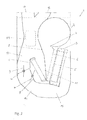
- Fig.1 shows a schematic sectional view of a portion of an air guide housing 1 of an air conditioner according to an embodiment.
- a fan 2 supplies the evaporator 3 with an air flow (not shown), which is conducted via a first air flow path 6.
- the first air flow path 6, which is designed as an air duct, is arranged between the evaporator 3 and the heating device 4.
- the first air flow path 6, starting at an air outlet 7 of the blower continues to the evaporator 3.
- the air supply channel has a wall 8 which is arranged between the evaporator 3 and the heating device 4.
- a ventilation air outlet 12 In the air guide housing 1, a ventilation air outlet 12, a Defrostluftaustritt 13 and a predominantlyraumluftauscher 14 are further provided, in which the cold air duct 10 and the hot air duct 11 open.
- the position of the second flap 9 shown in the figure corresponds to a position "cold", in which the air via the cold air duct 10 is headed.
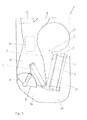
- Fig. 2 shows before schematic sectional view of a portion of an air guide housing 1 of an air conditioner according to another embodiment.
- two second flaps 9, 9 ' are provided here, which direct the exiting the evaporator 3 air flow in the cold air duct 10 or the hot air duct 11.
- position of the two second flaps 9, 9 ' corresponds to a position "cold” and indicated by the dashed line "w" position of the two second flaps 9, 9' corresponds to a position "warm”.
- the inflow of the air flow from the evaporator 3 to the heater 4 is analogous to that already in connection with Fig. 1 described,
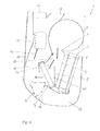
- Fig. 3 shows a schematic sectional view of a portion of an air guide housing 1 of an air conditioner according to yet another embodiment.
- the embodiment illustrated here differs from that already described in connection with FIG Fig. 1 described only in that the second flap 9 is designed here as a so-called barrel door mixing flap.
- the second flap 9 is located in a position "cold", wherein by the dashed line, which is indicated by "w”, the position "warm” is indicated.
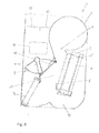
- Fig. 4 shows a schematic sectional view of a portion of an air guide housing 1 of an air conditioner according to yet another embodiment.
- the arrangement of the heater 4 with respect to the second flap 9 differs from the previous embodiments, which in Fig. 1 to Fig. 3 are shown.
- the inflow of the air flow via the second air flow path 15 under the evaporator 3 to the heater 4 takes place in contrast to those already in Fig. 1 to Fig. 3
- the cold path that is, the air flow, when the mixing flap is in the "cold" position, passed over the heater 4 ago.
- Fig. 5 shows a schematic sectional view of a portion of an air guide housing 1 of an air conditioner according to yet another embodiment, which differs from the in Fig. 4 shown embodiment differs in that the inflow of the air flow via a third air flow path 16, which extends over the evaporator 3, takes place to the heater 4.
- Fig. 6 shows a schematic sectional view of a portion of an air guide housing 1 of an air conditioner according to yet another embodiment
- the structure and components of this embodiment substantially correspond to those in Fig. 3
- the difference from the embodiment of FIG Fig. 3 is, however, that in the wall 8, an opening 17 is provided, soft by a simple, arranged in the opening 17 first cap 18 closed.
- the first flap 18 is disposed between the first air flow path 6 and the warm air channel 11.
- the evaporator 3 is no longer flowed through by the blower, 2 coming air flow L w .
- the air flow in operating mode "maximum warm" is passed directly through the heater 4, resulting in a significantly reduced air-side pressure drop.
- Fig. 7 shows a further schematic sectional view of the portion of the air guide housing 1 of the air conditioning of Fig. 6 , which does not work in "maximum warm” mode but in mixed mode.
- an air flow coming from the blower 2 is passed through the heating device 4 and heated there.
- a portion of the air flow coming from the blower 2 is conducted past the evaporator 3 to the cold air duct 10.
- the cold air flow and the hot air flow are then mixed and forwarded together to either the ventilation air outlet 12, the defrost air outlet 13 or the footwell air outlet 14.
- Fig. 8 shows a schematic sectional view of a portion of an air guide housing 1 of an air conditioner according to still another embodiment, In contrast to the in Fig. 7 In the embodiment shown, the second flap 9 is not arranged behind the heating device 4 but above it,
- Fig. 9a, 9b . 9c show respective schematic sectional views of the in Fig. 8 shown embodiment in different operating modes.
- Fig. 9a In this case, an operating mode "maximum warm” is shown, wherein the coming of the fan 2 air flow is passed to the evaporator 3 over or bypasses this and is passed directly to the heater 4, wherein the air is heated when passing through the heater 4.
- Fig. 9a In this case, an operating mode "maximum warm" is shown, wherein the coming of the fan 2 air flow is passed to the evaporator 3 over or bypasses this and is passed directly to the heater 4, wherein the air is heated when passing through the heater 4.
- FIG. 9b is a mode of operation "maximum warm” shown with simultaneous dehumidifying operation coming from the blower 2 air flow is passed through the evaporator 3 via the under the evaporator 3 derived extended flow path - the second air flow path 15 - to the heater 4, wherein the dehumidified air when passing through the heater 4 is heated and as needed the. Ventilation air outlet 12, the defrost air outlet 13 or the footwell air outlet 14 is supplied.
- Fig. 9c an operating mode in which the evaporator for dehumidifying the air flow is flowed through and the air conducted via the second air flow path 15 is then divided between the cold air duct 10 and the hot air duct 11,
- a space-saving configuration can be provided with the air conditioning system according to the invention, with which a pressure drop in the heating mode and evaporation of possibly separated from the evaporator condensation on the heater can be effectively avoided.
Abstract
Description
Die Erfindung betrifft eine Klimaanlage, insbesondere für ein Kraftfahrzeug, gemäß dem Oberbegriff des Anspruchs 1.The invention relates to an air conditioning system, in particular for a motor vehicle, according to the preamble of
In Klimaanlagen, wie beispielsweise in Kraftfahrzeugklimaanlagen, können Betriebszustände auftreten, welche zu einem Kondenswasseraustritt aus dem Verdampfer führen. Dies kann z. B. durch starkes Beschleunigen oder Bremsen des Kraftfahrzeugs, einen sprunghaften Anstieg der Luftmenge oder sogar durch die Verdampferoberfläche kontaminierende oder verändernde Umwelteinflüsse verursacht werden. Problematisch ist eine derartige Situation dann, wenn das austretende Kondenswasser auf die Heizeinrichtung der Klimaanlage trifft. Dann besteht die Gefahr, dass das an der Heizeinrichtung verdampfende Kondenswasser zu einem Beschlagen der Fahrzeugscheiben - was insbesondere problematisch im Hinblick auf die Windschutzscheibe ist - und somit zu einer Sichtbehinderung führt.In air conditioning systems, such as in motor vehicle air conditioning systems, operating conditions may occur which lead to a condensation out of the evaporator. This can be z. B. caused by strong acceleration or braking of the motor vehicle, a sudden increase in the amount of air or even by the evaporator surface contaminating or changing environmental influences. Such a situation is problematic when the leaking condensate meets the heater of the air conditioner. Then there is a risk that the condensation water evaporating on the heating device leads to fogging of the vehicle windows - which is particularly problematic with regard to the windscreen - and thus leads to a visual obstruction.
Darüber hinaus werden im Rahmen der Hybridisierung von Kraftfahrzeugantrieben und bei überwiegend elektrisch angetriebenen Fahrzeugen bei aus dem Stand der Technik bekannten Konfigurationen durch Kühlflüssigkeit durchströmte Heizkörper durch elektrische Heizelemente, wie beispielsweise PTC-Heizelemente ersetzt. Um die nötige Heizleistung bei nicht zu hohen elektrischen Strömen zu erzielen, ist eine Anhebung der Versorgungsspannung über den heute im Kraftfahrzeugbetrieb üblichen Bereich von 12 bis 42 V notwendig. Man verlässt hier jedoch den sogenannten SELV-Bereich (Safety Extra Low Voltage, DIN VDE 100-410), bei dem keine besonderen Vorkehrungen bezüglich einer Berührung von spannungsführenden Teilen getroffen werden müssen. Daher ist auch eine Benetzung des Zuheizers mit Wasser im SELV Spannungsbereich als nicht so kritisch einzustufen. Bei einem höheren Spannungsniveau ist dies bei der Auslegung als möglicher Versagensfall mit aufzunehmen, falls von der Klimagerätearchitektur her nicht sichergestellt werden kann, dass möglicherweise aus dem Verdampfer austretendes Kondenswasser nicht den elektrischen Heizer benetzt.In addition, as part of the hybridization of motor vehicle drives and in predominantly electrically powered vehicles in known from the prior art configurations through which coolant flows through radiator replaced by electrical heating elements, such as PTC heating elements. To the necessary heating power at not too high To achieve electrical currents, an increase in the supply voltage over the current range of vehicle operation is 12 to 42 V necessary. Here, however, one leaves the so-called SELV range (Safety Extra Low Voltage, DIN VDE 100-410), in which no special precautions must be taken with regard to contact with live parts. Therefore, a wetting of the auxiliary heater with water in the SELV voltage range is classified as not so critical. At a higher voltage level, this should be included in the design as a potential failure case if the air conditioner architecture can not assure that any condensate escaping from the evaporator will not wet the electric heater.
Um dieser Problematik zu begegnen, ist beispielsweise aus
Obwohl verschiedene geometrische Anordnungen der Komponenten der Klimaanlage im Luftströmungsweg in dieser Hinsicht im Stand der Technik bekannt sind, besteht der grundlegende Aufbau im Luftströmungsweg entlang der Achse der Fahrtrichtung des Kraftfahrzeugs jedoch in der Regel aus der folgenden Reihenfolge: Zuströmung zum Verdampfer, Verdampfer, Heizkörper. Trotz der sehr unterschiedlichen möglichen geometrischen Anordnungen von Heizkörper und Verdampfer, folgen alle aus dem Stand der Technik bekannten Geräte der obigen Grundstruktur, bei der die Verdampferaustrittseite in Richtung des Heizkörpers weist, wodurch die oben beschriebene Gefahr besteht, dass aus dem Verdampfer austretendes Kondenswasser den Heizkörper bzw. einen elektrischen Zuheizer benetzt.Although various geometric arrangements of the components of the air conditioning system in the air flow path in this regard are known in the art, the basic structure in the air flow path along the axis of the direction of travel of the motor vehicle, however, usually consists of the following order: inflow to the evaporator, evaporator, radiator. Despite the very different possible geometric Arrangements of radiator and evaporator, follow all known from the prior art devices of the above basic structure, wherein the evaporator outlet side faces in the direction of the radiator, whereby the above-described risk that exiting from the evaporator condensate wets the radiator or an electric heater ,
Die aus dem Stand der Technik bekannten Lösungen, um diese Gefahr zu minimieren oder zu vermeiden, erfordern spezielle Bauräume oder besondere geometrische Relationen zwischen Verdampfer und Heizkörper, was die Komplexität und somit die Kosten negativ beeinflusst.The known from the prior art solutions to minimize or avoid this danger, require special space or special geometric relations between evaporator and radiator, which negatively affects the complexity and thus the cost.
Ein weiteres Problem bei den aus dem Stand der Technik bekannten Anordnungen beruht darauf, dass der Verdampfer in einer Klimaanlage technisch bedingt Luft nur auf Temperaturen knapp oberhalb von 0 °C abkühlen kann. Bei tieferen Lufttemperaturen würde das im Verdampfer abgeschiedene Kondenswasser gefrieren und den Verdampfer luftseitig verschließen. Deshalb wird der Kältekreislauf spätestens bei Außentemperaturen von kleiner als 0 °C abgeschaltet. Der Verdampfer ist dann ohne Funktion. In einem Temperaturbereich oberhalb von 0 °C (typischerweise in einem Bereich von 0 - 15 °C) ist ein Verdampferbetrieb zur Aufrechterhaltung einer konstanten Kraftfahrzeuginnenraumtemperatur nicht immer notwendig. Er wird jedoch zur Entfeuchtung der in den Kraftfahrzeuginnenraum eingebrachten Luft verwendet, Diese Maßnahme verhindert wirkungsvoll ein Beschlagen der Fahrzeugscheiben und trägt damit wesentlich zu einer erhöhten Verkehrssicherheit des Kraftfahrzeugs bei. Im Heizbetrieb unter 0 °C ist - wie oben beschrieben - der Verdampfer ohne Funktion; er verursacht im Luftweg der Klimaanlage dabei nur noch einen zusätzlichen luftseitigen Druckabfall, der zu Überwinden ist. Dies zeigt sich entweder in einer reduzierten Luftmenge im Heizbetrieb und/oder einer erhöhten Stromaufnahme bzw. Leistungsabgabe des Gebläses, was oft mit einer Verschlechterung der Akustik verbunden ist.Another problem with the known from the prior art arrangements is based on the fact that the evaporator can cool air in an air conditioner only to temperatures just above 0 ° C. At lower air temperatures, the condensate deposited in the evaporator would freeze and close the evaporator on the air side. Therefore, the refrigeration cycle is switched off at the latest at outside temperatures of less than 0 ° C. The evaporator is then without function. In a temperature range above 0 ° C (typically in a range of 0-15 ° C), evaporator operation is not always necessary to maintain a constant vehicle interior temperature. However, it is used for dehumidifying the introduced into the motor vehicle interior air, this measure effectively prevents fogging of the vehicle windows and thus contributes significantly to increased road safety of the motor vehicle. In heating mode below 0 ° C - as described above - the evaporator without function; it causes in the airway of the air conditioner while only an additional air-side pressure drop, which is to overcome. This manifests itself either in a reduced amount of air in the heating mode and / or an increased power consumption or output of the fan, which is often associated with a deterioration of the acoustics.
Um diese Problematik zu lösen, sind Klimaanlagen im Stand der Technik bekannt, die statt einer Reihenschaltung des Verdampfers und der Heizeinrichtung eine Parallelschaltung von Verdampfer und Heizeinrichtung vorschlagen.To solve this problem, air conditioners are known in the art, which propose a parallel circuit of evaporator and heater instead of a series circuit of the evaporator and the heater.
Beispielsweise wird in
Hierbei wird zwar im Heizbetrieb eine Umgehung des Verdampfers und damit ein reduzierter Druckabfall im Heizmodus ermöglicht, jedoch ist nachteilig, dass eine vollständige Entfeuchtung der Luft nicht mehr möglich ist, was wiederum die bereits oben beschriebenen Probleme verursacht, wenn Feuchtigkeit an die Heizeinrichtungen der Klimaanlage gelangt.Although in the heating mode, a bypass of the evaporator and thus a reduced pressure drop in the heating mode is possible, but it is disadvantageous that a complete dehumidification of the air is no longer possible, which in turn causes the problems already described above, when moisture reaches the heaters of the air conditioner ,
Besonders bei niedrigen Außentemperaturen, insbesondere bei Temperaturen unterhalb von 10 °C, wo oft hohe Luftmengen über die Heizeinrichtung strömen und nur geringe Luftmengen über den Verdampfer, kann hierbei keine ausreichende Entfeuchtung der in den Fahrzeuginnenraum eintretenden Luft gewährleistet werden, und damit besteht wiederum die Gefahr des Beschlagens der Fahrzeugscheiben.Especially at low outdoor temperatures, especially at temperatures below 10 ° C, where often flow high amounts of air through the heater and only small amounts of air through the evaporator, this can not ensure sufficient dehumidification of entering the vehicle interior air, and thus again there is a risk the fogging of the vehicle windows.
Daher ist es die Aufgabe der vorliegenden Erfindung, eine Klimaanlage für ein Kraftfahrzeug zur Verfügung zu stellen, bei welcher ohne das Erfordernis zusätzlichen Bauraums eine Konfiguration realisiert wird, bei der weder Druckverluste noch ein Benetzen der Heizeinrichtung mit Wasser auftreten.Therefore, it is the object of the present invention to provide an air conditioning system for a motor vehicle, in which without the requirement of additional space, a configuration is realized in which neither pressure losses nor wetting of the heater with water occur.
Die Aufgabe der vorliegenden Erfindung wird durch eine Klimaanlage mit den Merkmalen gemäß Anspruch 1 gelöst. Vorteilhafte Weiterbildungen der vorliegenden Erfindung sind in den Unteransprüchen definiert.The object of the present invention is achieved by an air conditioner having the features according to
Erfindungsgemäß wird eine Klimaanlage, insbesondere für ein Kraftfahrzeug, bereitgestellt, welche ein Luftführungsgehäuse aufweist, in welchem zumindest ein Gebläse, ein Verdampfer und eine Heizeinrichtung angeordnet sind, wobei das Gebläse dem Verdampfer und/oder der Heizeinrichtung einen Luftstrom zuführt, wobei ein erster Luftströmungsweg zum Zuführen des Luftstroms zu dem Verdampfer und/oder der Heizeinrichtung zwischen dem Verdampfer und der Heizeinrichtung angeordnet ist. Dadurch, dass die Zuströmung des Luftstroms zu dem Verdampfer räumlich zwischen dem Verdampfer und der Heizeinrichtung liegt, wird einerseits das Vorsehen eines längeren Strömungswegs von einem Verdampferaustritt zu der Heizeinrichtung ermöglicht, wodurch eine ausreichende Entfeuchtung sichergestellt wird, da durch den längeren Strömungsweg möglicherweise aus dem Verdampfer austretendes Kondenswasser besser abgeschieden werden kann. Andererseits erlaubt es diese Konfiguration, den Verdampfer, wenn er nicht in Betrieb ist, zu umgehen, um so den luftseitigen Druckabfall zu reduzieren. Diese Lösung erfordert darüber hinaus keinen zusätzlichen Bauraum oder bestimmte Gehäusegeometrien.According to the invention, an air conditioning system, in particular for a motor vehicle, is provided, which has an air duct housing in which at least one blower, an evaporator and a heater are arranged, wherein the blower supplies an air flow to the evaporator and / or the heater, a first air flow path to Supplying the air flow to the evaporator and / or the heating device between the evaporator and the heater is arranged. Characterized in that the inflow of the air flow to the evaporator is spatially between the evaporator and the heater, on the one hand, the provision of a longer flow path from an evaporator outlet to the heater allows, whereby sufficient dehumidification is ensured because of the longer flow path possibly from the evaporator Emerging condensation can be better separated. On the other hand, this configuration allows bypassing the evaporator when it is not in operation, thus reducing airside pressure drop. In addition, this solution requires no additional space or specific housing geometries.
Gemäß einer bevorzugten Ausführungsform ist der erste Luftströmungsweg an einem Luftaustritt des Gebläses angeordnet.According to a preferred embodiment, the first air flow path is arranged at an air outlet of the blower.
Gemäß noch einer bevorzugten Ausführungsform ist der erste Luftströmungsweg als Luftzuführkanal in dem Luftführungsgehäuse ausgebildet.According to yet a preferred embodiment, the first air flow path is formed as an air supply passage in the air guide housing.
Gemäß noch einer weiteren bevorzugten Ausführungsform weist der Luftzuführkanal eine Wandung auf, welche zwischen dem Verdampfer und dem Heizeinrichtung angeordnet ist.According to yet another preferred embodiment, the air supply duct has a wall which is arranged between the evaporator and the heating device.
Vorzugsweise ist in der Wandung eine Öffnung vorgesehen,Preferably, an opening is provided in the wall,
Noch bevorzugter ist es, wenn in der Öffnung eine erste Klappe zum Öffnen und Verschließen der Öffnung angeordnet ist. Die erste Klappe, welche die Öffnung in der Wandung des Luftzuführkanals freigeben und schließen kann, ermöglicht sowohl eine Parallel- als auch eine Reihenschaltung von Verdampfer und Heizeinrichtung.It is even more preferable if a first flap for opening and closing the opening is arranged in the opening. The first flap, which can open and close the opening in the wall of the air supply channel, allows both a parallel and a series circuit of evaporator and heater.
Gemäß einer weiteren bevorzugten Ausführungsform regelt die erste Klappe eine Reihenschaltung oder eine Parallelschaltung des Verdampfers und der Heizeinrichtung bezüglich des durch den ersten Luftströmungsweg zugeführten Luftstroms.According to a further preferred embodiment, the first flap regulates a series connection or a parallel connection of the evaporator and the heater with respect to the air flow supplied through the first air flow path.
Gemäß noch einer weiteren bevorzugten Ausführungsform wird in der Reihenschaltung der Luftstrom von dem ersten Luftströmungsweg ausschließlich zu dem Verdampfer geleitet. Hinter dem Verdampfer wird die Luftströmung dann von einer oder mehreren Mischklappen entsprechend den Anforderungen (Solltemperatur) auf einen Kalt- und/oder Warmweg verteilt. In diesem Modus wird auch eine vollständige Entfeuchtung des Luftstroms sichergestellt. Bei Öffnen der Klappe wird aufgrund der Anordnung des ersten Luftströmungswegs zwischen dem Verdampfer und der Heizeinrichtung eine direkte Beaufschlagung der Heizeinrichtung unter Umgehung des Verdampfers ermöglicht.According to yet another preferred embodiment, in the series connection, the air flow from the first air flow path is directed exclusively to the evaporator. Behind the evaporator, the air flow is then distributed by one or more mixing flaps according to the requirements (target temperature) on a cold and / or warm way. In This mode also ensures complete dehumidification of the airflow. Upon opening the flap, a direct loading of the heater, bypassing the evaporator, is made possible due to the arrangement of the first air flow path between the evaporator and the heater.
Vorzugsweise leitet eine hinter dem Verdampfer angeordnete zweite Klappe den aus dem Verdampfer austretenden Luftstrom in einen Kaltluftkanal und/oder einen Warmluftkanal.Preferably, a second flap arranged behind the evaporator directs the air flow emerging from the evaporator into a cold air duct and / or a hot air duct.
Es ist darüber hinaus bevorzugt, wenn die zweite Klappe als Mischklappe ausgebildet ist.It is also preferred if the second flap is designed as a mixing flap.
Gemäß einer weiteren bevorzugten Ausführungsform ist eine Luftaustrittsseite des Verdampfers durch die zweite Klappe verschließbar. Wenn die zweite Klappe die Luftaustrittsseite des Verdampfers verschließt, findet in diesem Fall keine Durchströmung des Verdampfers mehr statt.According to a further preferred embodiment, an air outlet side of the evaporator can be closed by the second flap. If the second flap closes the air outlet side of the evaporator, no flow through the evaporator takes place in this case.
Auch ist es besonders vorteilhaft, wenn ein zweiter Luftströmungsweg von der Luftaustrittsseite des Verdampfers zu der Heizeinrichtung unterhalb des Verdampfers angeordnet ist. Durch Anordnen des zweiten Luftströmungswegs von der Luftaustrittsseite des Verdampfers zu der Heizeinrichtung unterhalb des Verdampfers wird der Strömungsweg vorteilhaft verlängert, so dass eine bessere Abscheidung von möglicherweise in der Luftströmung mitgeführtem Kondenswasser erzielt wird.It is also particularly advantageous if a second air flow path from the air outlet side of the evaporator to the heating device is arranged below the evaporator. By arranging the second air flow path from the air outlet side of the evaporator to the heater below the evaporator, the flow path is advantageously lengthened so that better separation of condensed water possibly entrained in the air flow is achieved.
Gemäß einer weiteren bevorzugten Ausführungsform kann ein dritter Luftströmungsweg von dem Luftaustritt des Verdampfers zu der Heizeinrichtung neben dem Verdampfer oder oberhalb des Verdampfers angeordnet sein. Auch diese Konfigurationen erzielen auf vorteilhafte Weise und ohne erhöhten Platzbedarf eine Verlängerung des Strömungswegs.According to a further preferred embodiment, a third air flow path from the air outlet of the evaporator to the heating device can be arranged next to the evaporator or above the evaporator. These configurations also achieve an extension of the flow path in an advantageous manner and without increased space requirements.
Vorzugsweise ist die Heizeinrichtung eine elektrische Heizeinrichtung, Darüber hinaus ist es bevorzugt, wenn die elektrische Heizeinrichtung zumindest ein PTC-Heizelement aufweist.Preferably, the heating device is an electric heating device. Moreover, it is preferred if the electric heating device has at least one PTC heating element.
Im Folgenden wird die Erfindung anhand eines Ausführungsbeispiels unter Bezugnahme auf die Zeichnung detailliert erläutert. In der Zeichnung zeigen:
- Fig.1
- eine schematische Schnittansicht eines Abschnitts eines Luftfüh- rungsgehäuses einer Klimaanlage gemäß einer Ausführungsform;
- Fig. 2
- eine schematische Schnittansicht eines Abschnitts eines Luftfüh- rungsgehäuses einer Klimaanlage gemäß einer weiteren Ausfüh- rungsform ;
- Fig. 3
- eine schematische Schnittansicht eines Abschnitts eines Luftfüh- rungsgehäuses einer Klimaanlage gemäß noch einer weiteren Aus- führungsform;
- Fig. 4
- eine schematische Schnittansicht eines Abschnitts eines Luftfüh- rungsgehäuses einer Klimaanlage gemäß noch einer weiteren Aus- führungsform;
- Fig. 5
- eine schematische Schnittansicht eines Abschnitts eines Luftfüh- rungsgehäuses einer Klimaanlage gemäß noch einer weiteren Aus- führungsform;
- Fig. 6
- eine schematische Schnittansicht eines Abschnitts eines Luftfüh- rungsgehäuses einer Klimaanlage gemäß noch einer weiteren Aus- führungsform;
- Fig. 7
- eine weitere schematische Schnittansicht des Abschnitts des Luft- führungsgehäuses der Klimaanlage von
Fig. 6 ; - Fig. 8
- eine schematische Schnittansicht eines Abschnitts eines Luftfüh- rungsgehäuses einer Klimaanlage gemäß noch einer weiteren Aus- führungsform; und
- Fig. 9a, 9b, 9c
- Jeweilige schematische Schnittansichten der in
Fig. 8 darges- tellten Ausführungsform.
- Fig.1
- a schematic sectional view of a portion of an air duct housing of an air conditioner according to an embodiment;
- Fig. 2
- a schematic sectional view of a portion of an air guide housing of an air conditioner according to another embodiment;
- Fig. 3
- a schematic sectional view of a portion of an air guide housing of an air conditioner according to yet another embodiment;
- Fig. 4
- a schematic sectional view of a portion of an air guide housing of an air conditioner according to yet another embodiment;
- Fig. 5
- a schematic sectional view of a portion of an air guide housing of an air conditioner according to yet another embodiment;
- Fig. 6
- a schematic sectional view of a portion of an air guide housing of an air conditioner according to yet another embodiment;
- Fig. 7
- Another schematic sectional view of the portion of the air guide housing of the air conditioning of
Fig. 6 ; - Fig. 8
- a schematic sectional view of a portion of an air guide housing of an air conditioner according to yet another embodiment; and
- Fig. 9a, 9b, 9c
- Respective schematic sectional views of the in
Fig. 8 illustrated embodiment.
Insgesamt betrachtet kann mit der erfindungsgemäßen Klimaanlage eine bauraumsparende Konfiguration bereitgestellt werden, mit der ein Druckabfall im Heizbetrieb sowie ein Verdampfen von möglicherweise aus dem Verdampfer abgeschiedenen Kondenswasser an der Heizeinrichtung effektiv vermieden werden kann.Overall, a space-saving configuration can be provided with the air conditioning system according to the invention, with which a pressure drop in the heating mode and evaporation of possibly separated from the evaporator condensation on the heater can be effectively avoided.
- 11
- LuftführungsgehäuseAir duct housing
- 22
- Gebläsefan
- 33
- VerdampferEvaporator
- 44
- Heizeinrichtungheater
- 55
- Filterfilter
- 66
- erster Luftströmungswegfirst air flow path
- 77
- Luftaustrittair outlet
- 88th
- Wandungwall
- 9, 9'9, 9 '
- zweite Klappesecond flap
- 1010
- KaltluftkanalCold air duct
- 1111
- WarmluftkanalWarm air duct
- 1212
- BelüftungsluftaustrittVentilation air outlet
- 1313
- DefrostluftaustrittDefrostluftaustritt
- 1414
- FußraumluftaustrittFootwell air outlet
- 1515
- zweiter Luftströmungswegsecond air flow path
- 1616
- dritter Luftströmungswegthird air flow path
- 1717
- Öffnungopening
- 1818
- erste Klappefirst flap
- 1919
- Mischraummixing room
- ww
- Stellung "wann"Position "when"
- Lw L w
- Luftströmung, warmAir flow, warm
- LK L K
- Luftströmung, kaltAir flow, cold
Claims (15)
Applications Claiming Priority (1)
| Application Number | Priority Date | Filing Date | Title |
|---|---|---|---|
| DE200910049425 DE102009049425A1 (en) | 2009-10-14 | 2009-10-14 | air conditioning |
Publications (2)
| Publication Number | Publication Date |
|---|---|
| EP2311675A1 true EP2311675A1 (en) | 2011-04-20 |
| EP2311675B1 EP2311675B1 (en) | 2013-12-11 |
Family
ID=43448518
Family Applications (1)
| Application Number | Title | Priority Date | Filing Date |
|---|---|---|---|
| EP10187118.4A Not-in-force EP2311675B1 (en) | 2009-10-14 | 2010-10-11 | Air conditioning device |
Country Status (2)
| Country | Link |
|---|---|
| EP (1) | EP2311675B1 (en) |
| DE (1) | DE102009049425A1 (en) |
Citations (7)
| Publication number | Priority date | Publication date | Assignee | Title |
|---|---|---|---|---|
| FR2531666A1 (en) * | 1982-08-11 | 1984-02-17 | Sueddeutsche Kuehler Behr | Air conditioner unit for vehicle |
| JPS60226315A (en) * | 1984-04-26 | 1985-11-11 | Nippon Denso Co Ltd | Air-conditioning device for automobile |
| DE19741862A1 (en) * | 1997-09-23 | 1999-03-25 | Daimler Benz Ag | Vehicle air conditioning unit |
| EP1510375A1 (en) | 2003-08-25 | 2005-03-02 | Behr France S.A.R.L. | Air conditioning installation and method for operating one such installation |
| US20050115704A1 (en) * | 2003-12-02 | 2005-06-02 | Koji Ito | Vehicle air conditioner |
| DE102004030672A1 (en) | 2003-06-24 | 2005-06-16 | Abouchaar, Nicolas, Dipl.-Ing. | Vehicle heater and air conditioning system, with a fan and air flow flap controls, has a cooling/heating exchanger and a heat exchanger in a V-shaped layout with their ends against each other in a compact structure |
| EP1568523B1 (en) | 2004-02-26 | 2007-06-13 | Behr France Rouffach SAS | Construction of heat exchanging device |
Family Cites Families (3)
| Publication number | Priority date | Publication date | Assignee | Title |
|---|---|---|---|---|
| JP2001287535A (en) * | 2000-04-07 | 2001-10-16 | Calsonic Kansei Corp | Vehicular air conditioner |
| DE10025083A1 (en) * | 2000-05-20 | 2001-11-22 | Behr Gmbh & Co | Vehicle air-conditioning unit has parallel cold and warm air ducts, air outlets, air flow unit and air control flap. |
| FR2833530B1 (en) * | 2001-12-18 | 2004-06-18 | Valeo Climatisation | HEATING AND / OR AIR CONDITIONING APPARATUS WITH MIXING AND AIR DISTRIBUTION MEMBER FOR MOTOR VEHICLE COCKPIT |
-
2009
- 2009-10-14 DE DE200910049425 patent/DE102009049425A1/en not_active Withdrawn
-
2010
- 2010-10-11 EP EP10187118.4A patent/EP2311675B1/en not_active Not-in-force
Patent Citations (7)
| Publication number | Priority date | Publication date | Assignee | Title |
|---|---|---|---|---|
| FR2531666A1 (en) * | 1982-08-11 | 1984-02-17 | Sueddeutsche Kuehler Behr | Air conditioner unit for vehicle |
| JPS60226315A (en) * | 1984-04-26 | 1985-11-11 | Nippon Denso Co Ltd | Air-conditioning device for automobile |
| DE19741862A1 (en) * | 1997-09-23 | 1999-03-25 | Daimler Benz Ag | Vehicle air conditioning unit |
| DE102004030672A1 (en) | 2003-06-24 | 2005-06-16 | Abouchaar, Nicolas, Dipl.-Ing. | Vehicle heater and air conditioning system, with a fan and air flow flap controls, has a cooling/heating exchanger and a heat exchanger in a V-shaped layout with their ends against each other in a compact structure |
| EP1510375A1 (en) | 2003-08-25 | 2005-03-02 | Behr France S.A.R.L. | Air conditioning installation and method for operating one such installation |
| US20050115704A1 (en) * | 2003-12-02 | 2005-06-02 | Koji Ito | Vehicle air conditioner |
| EP1568523B1 (en) | 2004-02-26 | 2007-06-13 | Behr France Rouffach SAS | Construction of heat exchanging device |
Also Published As
| Publication number | Publication date |
|---|---|
| EP2311675B1 (en) | 2013-12-11 |
| DE102009049425A1 (en) | 2011-04-21 |
Similar Documents
| Publication | Publication Date | Title |
|---|---|---|
| DE102012111672B4 (en) | Refrigerant circuit of an air conditioning system with heat pump and reheat functionality | |
| DE112017002430B4 (en) | Air conditioning unit for a vehicle | |
| DE102015117962A1 (en) | Air conditioning system for conditioning the air of a passenger compartment of a motor vehicle | |
| DE102017116191B4 (en) | Air conditioning system for multi-zone air conditioning of a vehicle interior | |
| DE102014224817A1 (en) | air conditioning | |
| DE102011053906A1 (en) | Dehumidifying unit and method | |
| DE102016214116A1 (en) | Air conditioning device for a motor vehicle | |
| DE102020007164A1 (en) | Air conditioning for a heat pump operation | |
| DE4341756C2 (en) | Air conditioning for a motor vehicle | |
| DE102006002233A1 (en) | Heating and air conditioning system used for vehicle, has two heat exchanger in housing and auxiliary heater driven with fuel is arranged in part of cold air volume | |
| DE102012214859A1 (en) | Air conditioning apparatus for motor vehicle e.g. motor car, has ventilation duct and/or defroster duct and/or foot area channel to which temperature-controlled air is provided, and separate air duct is provided | |
| DE10256619B3 (en) | Air conditioner for vehicles | |
| EP2311675B1 (en) | Air conditioning device | |
| EP1568523B1 (en) | Construction of heat exchanging device | |
| EP2277728B1 (en) | Air conditioning device | |
| WO2007003145A1 (en) | Air conditioning system for a vehicle | |
| EP1285788B1 (en) | Air conditioning device | |
| DE19835286B4 (en) | Heating or air conditioning of a vehicle | |
| WO1996009180A1 (en) | Air conditioning system for a motor vehicle | |
| EP1407903B1 (en) | Air conditioning unit of a motor vehicle comprising an air distribution device | |
| DE102010042051A1 (en) | Air conditioner for motor vehicle, has evaporator and heater, where air flow is conducted into mixing chamber through cold-air duct or warm air duct, and cold-air duct or warm air duct is controlled by stratification valves | |
| DE102004030672B4 (en) | V-shaped heat exchanger arrangement of a heating air conditioning | |
| DE10314803B4 (en) | Method for dehumidifying and tempering an airflow | |
| EP2508369A1 (en) | Air conditioning for the interior of a vehicle using an air adjustment device | |
| DE102015122348A1 (en) | Heating and air conditioning for a motor vehicle |
Legal Events
| Date | Code | Title | Description |
|---|---|---|---|
| PUAI | Public reference made under article 153(3) epc to a published international application that has entered the european phase |
Free format text: ORIGINAL CODE: 0009012 |
|
| AK | Designated contracting states |
Kind code of ref document: A1 Designated state(s): AL AT BE BG CH CY CZ DE DK EE ES FI FR GB GR HR HU IE IS IT LI LT LU LV MC MK MT NL NO PL PT RO RS SE SI SK SM TR |
|
| AX | Request for extension of the european patent |
Extension state: BA ME |
|
| 17P | Request for examination filed |
Effective date: 20111020 |
|
| 17Q | First examination report despatched |
Effective date: 20121106 |
|
| GRAP | Despatch of communication of intention to grant a patent |
Free format text: ORIGINAL CODE: EPIDOSNIGR1 |
|
| INTG | Intention to grant announced |
Effective date: 20130621 |
|
| GRAS | Grant fee paid |
Free format text: ORIGINAL CODE: EPIDOSNIGR3 |
|
| GRAA | (expected) grant |
Free format text: ORIGINAL CODE: 0009210 |
|
| AK | Designated contracting states |
Kind code of ref document: B1 Designated state(s): AL AT BE BG CH CY CZ DE DK EE ES FI FR GB GR HR HU IE IS IT LI LT LU LV MC MK MT NL NO PL PT RO RS SE SI SK SM TR |
|
| REG | Reference to a national code |
Ref country code: GB Ref legal event code: FG4D Free format text: NOT ENGLISH |
|
| REG | Reference to a national code |
Ref country code: CH Ref legal event code: EP |
|
| REG | Reference to a national code |
Ref country code: AT Ref legal event code: REF Ref document number: 644328 Country of ref document: AT Kind code of ref document: T Effective date: 20140115 |
|
| REG | Reference to a national code |
Ref country code: IE Ref legal event code: FG4D Free format text: LANGUAGE OF EP DOCUMENT: GERMAN |
|
| REG | Reference to a national code |
Ref country code: DE Ref legal event code: R096 Ref document number: 502010005607 Country of ref document: DE Effective date: 20140206 |
|
| REG | Reference to a national code |
Ref country code: NL Ref legal event code: VDEP Effective date: 20131211 |
|
| PG25 | Lapsed in a contracting state [announced via postgrant information from national office to epo] |
Ref country code: NO Free format text: LAPSE BECAUSE OF FAILURE TO SUBMIT A TRANSLATION OF THE DESCRIPTION OR TO PAY THE FEE WITHIN THE PRESCRIBED TIME-LIMIT Effective date: 20140311 Ref country code: HR Free format text: LAPSE BECAUSE OF FAILURE TO SUBMIT A TRANSLATION OF THE DESCRIPTION OR TO PAY THE FEE WITHIN THE PRESCRIBED TIME-LIMIT Effective date: 20131211 Ref country code: FI Free format text: LAPSE BECAUSE OF FAILURE TO SUBMIT A TRANSLATION OF THE DESCRIPTION OR TO PAY THE FEE WITHIN THE PRESCRIBED TIME-LIMIT Effective date: 20131211 Ref country code: SE Free format text: LAPSE BECAUSE OF FAILURE TO SUBMIT A TRANSLATION OF THE DESCRIPTION OR TO PAY THE FEE WITHIN THE PRESCRIBED TIME-LIMIT Effective date: 20131211 Ref country code: LT Free format text: LAPSE BECAUSE OF FAILURE TO SUBMIT A TRANSLATION OF THE DESCRIPTION OR TO PAY THE FEE WITHIN THE PRESCRIBED TIME-LIMIT Effective date: 20131211 Ref country code: NL Free format text: LAPSE BECAUSE OF FAILURE TO SUBMIT A TRANSLATION OF THE DESCRIPTION OR TO PAY THE FEE WITHIN THE PRESCRIBED TIME-LIMIT Effective date: 20131211 |
|
| REG | Reference to a national code |
Ref country code: LT Ref legal event code: MG4D |
|
| PG25 | Lapsed in a contracting state [announced via postgrant information from national office to epo] |
Ref country code: RS Free format text: LAPSE BECAUSE OF FAILURE TO SUBMIT A TRANSLATION OF THE DESCRIPTION OR TO PAY THE FEE WITHIN THE PRESCRIBED TIME-LIMIT Effective date: 20131211 Ref country code: CY Free format text: LAPSE BECAUSE OF FAILURE TO SUBMIT A TRANSLATION OF THE DESCRIPTION OR TO PAY THE FEE WITHIN THE PRESCRIBED TIME-LIMIT Effective date: 20131211 Ref country code: LV Free format text: LAPSE BECAUSE OF FAILURE TO SUBMIT A TRANSLATION OF THE DESCRIPTION OR TO PAY THE FEE WITHIN THE PRESCRIBED TIME-LIMIT Effective date: 20131211 |
|
| PG25 | Lapsed in a contracting state [announced via postgrant information from national office to epo] |
Ref country code: EE Free format text: LAPSE BECAUSE OF FAILURE TO SUBMIT A TRANSLATION OF THE DESCRIPTION OR TO PAY THE FEE WITHIN THE PRESCRIBED TIME-LIMIT Effective date: 20131211 Ref country code: IS Free format text: LAPSE BECAUSE OF FAILURE TO SUBMIT A TRANSLATION OF THE DESCRIPTION OR TO PAY THE FEE WITHIN THE PRESCRIBED TIME-LIMIT Effective date: 20140411 |
|
| PG25 | Lapsed in a contracting state [announced via postgrant information from national office to epo] |
Ref country code: PL Free format text: LAPSE BECAUSE OF FAILURE TO SUBMIT A TRANSLATION OF THE DESCRIPTION OR TO PAY THE FEE WITHIN THE PRESCRIBED TIME-LIMIT Effective date: 20131211 Ref country code: ES Free format text: LAPSE BECAUSE OF FAILURE TO SUBMIT A TRANSLATION OF THE DESCRIPTION OR TO PAY THE FEE WITHIN THE PRESCRIBED TIME-LIMIT Effective date: 20131211 Ref country code: SK Free format text: LAPSE BECAUSE OF FAILURE TO SUBMIT A TRANSLATION OF THE DESCRIPTION OR TO PAY THE FEE WITHIN THE PRESCRIBED TIME-LIMIT Effective date: 20131211 Ref country code: CZ Free format text: LAPSE BECAUSE OF FAILURE TO SUBMIT A TRANSLATION OF THE DESCRIPTION OR TO PAY THE FEE WITHIN THE PRESCRIBED TIME-LIMIT Effective date: 20131211 Ref country code: RO Free format text: LAPSE BECAUSE OF FAILURE TO SUBMIT A TRANSLATION OF THE DESCRIPTION OR TO PAY THE FEE WITHIN THE PRESCRIBED TIME-LIMIT Effective date: 20131211 Ref country code: PT Free format text: LAPSE BECAUSE OF FAILURE TO SUBMIT A TRANSLATION OF THE DESCRIPTION OR TO PAY THE FEE WITHIN THE PRESCRIBED TIME-LIMIT Effective date: 20140411 |
|
| REG | Reference to a national code |
Ref country code: DE Ref legal event code: R097 Ref document number: 502010005607 Country of ref document: DE |
|
| PLBE | No opposition filed within time limit |
Free format text: ORIGINAL CODE: 0009261 |
|
| STAA | Information on the status of an ep patent application or granted ep patent |
Free format text: STATUS: NO OPPOSITION FILED WITHIN TIME LIMIT |
|
| PG25 | Lapsed in a contracting state [announced via postgrant information from national office to epo] |
Ref country code: DK Free format text: LAPSE BECAUSE OF FAILURE TO SUBMIT A TRANSLATION OF THE DESCRIPTION OR TO PAY THE FEE WITHIN THE PRESCRIBED TIME-LIMIT Effective date: 20131211 |
|
| 26N | No opposition filed |
Effective date: 20140912 |
|
| REG | Reference to a national code |
Ref country code: DE Ref legal event code: R097 Ref document number: 502010005607 Country of ref document: DE Effective date: 20140912 |
|
| PG25 | Lapsed in a contracting state [announced via postgrant information from national office to epo] |
Ref country code: SI Free format text: LAPSE BECAUSE OF FAILURE TO SUBMIT A TRANSLATION OF THE DESCRIPTION OR TO PAY THE FEE WITHIN THE PRESCRIBED TIME-LIMIT Effective date: 20131211 |
|
| REG | Reference to a national code |
Ref country code: DE Ref legal event code: R082 Ref document number: 502010005607 Country of ref document: DE Representative=s name: GRAUEL, ANDREAS, DIPL.-PHYS. DR. RER. NAT., DE |
|
| REG | Reference to a national code |
Ref country code: DE Ref legal event code: R082 Ref document number: 502010005607 Country of ref document: DE Representative=s name: GRAUEL, ANDREAS, DIPL.-PHYS. DR. RER. NAT., DE Effective date: 20150324 Ref country code: DE Ref legal event code: R081 Ref document number: 502010005607 Country of ref document: DE Owner name: MAHLE INTERNATIONAL GMBH, DE Free format text: FORMER OWNER: BEHR GMBH & CO. KG, 70469 STUTTGART, DE Effective date: 20150324 |
|
| PG25 | Lapsed in a contracting state [announced via postgrant information from national office to epo] |
Ref country code: MC Free format text: LAPSE BECAUSE OF FAILURE TO SUBMIT A TRANSLATION OF THE DESCRIPTION OR TO PAY THE FEE WITHIN THE PRESCRIBED TIME-LIMIT Effective date: 20131211 Ref country code: LU Free format text: LAPSE BECAUSE OF FAILURE TO SUBMIT A TRANSLATION OF THE DESCRIPTION OR TO PAY THE FEE WITHIN THE PRESCRIBED TIME-LIMIT Effective date: 20141011 |
|
| REG | Reference to a national code |
Ref country code: CH Ref legal event code: PL |
|
| GBPC | Gb: european patent ceased through non-payment of renewal fee |
Effective date: 20141011 |
|
| PG25 | Lapsed in a contracting state [announced via postgrant information from national office to epo] |
Ref country code: BE Free format text: LAPSE BECAUSE OF NON-PAYMENT OF DUE FEES Effective date: 20141031 |
|
| REG | Reference to a national code |
Ref country code: IE Ref legal event code: MM4A |
|
| PG25 | Lapsed in a contracting state [announced via postgrant information from national office to epo] |
Ref country code: CH Free format text: LAPSE BECAUSE OF NON-PAYMENT OF DUE FEES Effective date: 20141031 Ref country code: LI Free format text: LAPSE BECAUSE OF NON-PAYMENT OF DUE FEES Effective date: 20141031 Ref country code: GB Free format text: LAPSE BECAUSE OF NON-PAYMENT OF DUE FEES Effective date: 20141011 |
|
| REG | Reference to a national code |
Ref country code: FR Ref legal event code: PLFP Year of fee payment: 6 |
|
| PG25 | Lapsed in a contracting state [announced via postgrant information from national office to epo] |
Ref country code: IE Free format text: LAPSE BECAUSE OF NON-PAYMENT OF DUE FEES Effective date: 20141011 |
|
| PG25 | Lapsed in a contracting state [announced via postgrant information from national office to epo] |
Ref country code: SM Free format text: LAPSE BECAUSE OF FAILURE TO SUBMIT A TRANSLATION OF THE DESCRIPTION OR TO PAY THE FEE WITHIN THE PRESCRIBED TIME-LIMIT Effective date: 20131211 |
|
| PG25 | Lapsed in a contracting state [announced via postgrant information from national office to epo] |
Ref country code: IT Free format text: LAPSE BECAUSE OF FAILURE TO SUBMIT A TRANSLATION OF THE DESCRIPTION OR TO PAY THE FEE WITHIN THE PRESCRIBED TIME-LIMIT Effective date: 20131211 Ref country code: BG Free format text: LAPSE BECAUSE OF FAILURE TO SUBMIT A TRANSLATION OF THE DESCRIPTION OR TO PAY THE FEE WITHIN THE PRESCRIBED TIME-LIMIT Effective date: 20131211 Ref country code: GR Free format text: LAPSE BECAUSE OF FAILURE TO SUBMIT A TRANSLATION OF THE DESCRIPTION OR TO PAY THE FEE WITHIN THE PRESCRIBED TIME-LIMIT Effective date: 20140312 |
|
| PG25 | Lapsed in a contracting state [announced via postgrant information from national office to epo] |
Ref country code: HU Free format text: LAPSE BECAUSE OF FAILURE TO SUBMIT A TRANSLATION OF THE DESCRIPTION OR TO PAY THE FEE WITHIN THE PRESCRIBED TIME-LIMIT; INVALID AB INITIO Effective date: 20101011 Ref country code: MT Free format text: LAPSE BECAUSE OF FAILURE TO SUBMIT A TRANSLATION OF THE DESCRIPTION OR TO PAY THE FEE WITHIN THE PRESCRIBED TIME-LIMIT Effective date: 20131211 Ref country code: TR Free format text: LAPSE BECAUSE OF FAILURE TO SUBMIT A TRANSLATION OF THE DESCRIPTION OR TO PAY THE FEE WITHIN THE PRESCRIBED TIME-LIMIT Effective date: 20131211 |
|
| REG | Reference to a national code |
Ref country code: FR Ref legal event code: PLFP Year of fee payment: 7 |
|
| REG | Reference to a national code |
Ref country code: AT Ref legal event code: MM01 Ref document number: 644328 Country of ref document: AT Kind code of ref document: T Effective date: 20151011 |
|
| PG25 | Lapsed in a contracting state [announced via postgrant information from national office to epo] |
Ref country code: AT Free format text: LAPSE BECAUSE OF NON-PAYMENT OF DUE FEES Effective date: 20151011 |
|
| REG | Reference to a national code |
Ref country code: FR Ref legal event code: PLFP Year of fee payment: 8 |
|
| PG25 | Lapsed in a contracting state [announced via postgrant information from national office to epo] |
Ref country code: MK Free format text: LAPSE BECAUSE OF FAILURE TO SUBMIT A TRANSLATION OF THE DESCRIPTION OR TO PAY THE FEE WITHIN THE PRESCRIBED TIME-LIMIT Effective date: 20131211 |
|
| REG | Reference to a national code |
Ref country code: FR Ref legal event code: PLFP Year of fee payment: 9 |
|
| PG25 | Lapsed in a contracting state [announced via postgrant information from national office to epo] |
Ref country code: AL Free format text: LAPSE BECAUSE OF FAILURE TO SUBMIT A TRANSLATION OF THE DESCRIPTION OR TO PAY THE FEE WITHIN THE PRESCRIBED TIME-LIMIT Effective date: 20131211 |
|
| PGFP | Annual fee paid to national office [announced via postgrant information from national office to epo] |
Ref country code: DE Payment date: 20181030 Year of fee payment: 9 |
|
| PGFP | Annual fee paid to national office [announced via postgrant information from national office to epo] |
Ref country code: FR Payment date: 20181026 Year of fee payment: 9 |
|
| REG | Reference to a national code |
Ref country code: DE Ref legal event code: R119 Ref document number: 502010005607 Country of ref document: DE |
|
| PG25 | Lapsed in a contracting state [announced via postgrant information from national office to epo] |
Ref country code: DE Free format text: LAPSE BECAUSE OF NON-PAYMENT OF DUE FEES Effective date: 20200501 |
|
| PG25 | Lapsed in a contracting state [announced via postgrant information from national office to epo] |
Ref country code: FR Free format text: LAPSE BECAUSE OF NON-PAYMENT OF DUE FEES Effective date: 20191031 |