EP2308813B1 - Porenbetonsteine sowie Verfahren und Vorrichtung zu ihrer Herstellung - Google Patents
Porenbetonsteine sowie Verfahren und Vorrichtung zu ihrer Herstellung Download PDFInfo
- Publication number
- EP2308813B1 EP2308813B1 EP20100169045 EP10169045A EP2308813B1 EP 2308813 B1 EP2308813 B1 EP 2308813B1 EP 20100169045 EP20100169045 EP 20100169045 EP 10169045 A EP10169045 A EP 10169045A EP 2308813 B1 EP2308813 B1 EP 2308813B1
- Authority
- EP
- European Patent Office
- Prior art keywords
- autoclave
- storage material
- heat
- aerated concrete
- fusion storage
- Prior art date
- Legal status (The legal status is an assumption and is not a legal conclusion. Google has not performed a legal analysis and makes no representation as to the accuracy of the status listed.)
- Active
Links
Images
Classifications
-
- C—CHEMISTRY; METALLURGY
- C04—CEMENTS; CONCRETE; ARTIFICIAL STONE; CERAMICS; REFRACTORIES
- C04B—LIME, MAGNESIA; SLAG; CEMENTS; COMPOSITIONS THEREOF, e.g. MORTARS, CONCRETE OR LIKE BUILDING MATERIALS; ARTIFICIAL STONE; CERAMICS; REFRACTORIES; TREATMENT OF NATURAL STONE
- C04B41/00—After-treatment of mortars, concrete, artificial stone or ceramics; Treatment of natural stone
- C04B41/45—Coating or impregnating, e.g. injection in masonry, partial coating of green or fired ceramics, organic coating compositions for adhering together two concrete elements
- C04B41/46—Coating or impregnating, e.g. injection in masonry, partial coating of green or fired ceramics, organic coating compositions for adhering together two concrete elements with organic materials
- C04B41/47—Oils, fats or waxes natural resins
- C04B41/478—Bitumen, asphalt, e.g. paraffin
-
- C—CHEMISTRY; METALLURGY
- C04—CEMENTS; CONCRETE; ARTIFICIAL STONE; CERAMICS; REFRACTORIES
- C04B—LIME, MAGNESIA; SLAG; CEMENTS; COMPOSITIONS THEREOF, e.g. MORTARS, CONCRETE OR LIKE BUILDING MATERIALS; ARTIFICIAL STONE; CERAMICS; REFRACTORIES; TREATMENT OF NATURAL STONE
- C04B41/00—After-treatment of mortars, concrete, artificial stone or ceramics; Treatment of natural stone
- C04B41/009—After-treatment of mortars, concrete, artificial stone or ceramics; Treatment of natural stone characterised by the material treated
-
- C—CHEMISTRY; METALLURGY
- C04—CEMENTS; CONCRETE; ARTIFICIAL STONE; CERAMICS; REFRACTORIES
- C04B—LIME, MAGNESIA; SLAG; CEMENTS; COMPOSITIONS THEREOF, e.g. MORTARS, CONCRETE OR LIKE BUILDING MATERIALS; ARTIFICIAL STONE; CERAMICS; REFRACTORIES; TREATMENT OF NATURAL STONE
- C04B41/00—After-treatment of mortars, concrete, artificial stone or ceramics; Treatment of natural stone
- C04B41/60—After-treatment of mortars, concrete, artificial stone or ceramics; Treatment of natural stone of only artificial stone
- C04B41/61—Coating or impregnation
- C04B41/62—Coating or impregnation with organic materials
-
- C—CHEMISTRY; METALLURGY
- C09—DYES; PAINTS; POLISHES; NATURAL RESINS; ADHESIVES; COMPOSITIONS NOT OTHERWISE PROVIDED FOR; APPLICATIONS OF MATERIALS NOT OTHERWISE PROVIDED FOR
- C09K—MATERIALS FOR MISCELLANEOUS APPLICATIONS, NOT PROVIDED FOR ELSEWHERE
- C09K5/00—Heat-transfer, heat-exchange or heat-storage materials, e.g. refrigerants; Materials for the production of heat or cold by chemical reactions other than by combustion
- C09K5/02—Materials undergoing a change of physical state when used
- C09K5/06—Materials undergoing a change of physical state when used the change of state being from liquid to solid or vice versa
- C09K5/063—Materials absorbing or liberating heat during crystallisation; Heat storage materials
Definitions
- the invention relates to aerated concrete blocks and methods and apparatus for producing the aerated concrete blocks.
- Autoclaves of aerated concrete blocks in the context of the present invention are hydrothermally hardened, open-pore, cut or uncut stones, their aqueous mixture before autoclaving by means of propellant pores or by admixing, from customary aqueous mixtures comprising at least one reactive CaO and at least one reactive SiO 2 component has been porosified by foam.
- Foamed concrete blocks produced using foam are also called foam concrete blocks.
- Autoclaved concrete blocks are, for example, planing stones, planning boards, wall elements, lintels, roofing tiles, cover plates or the like and large-format and usually cuboid with different, usually standardized dimensions.
- Aerated concrete blocks have very good thermal insulation properties.
- the purpose of the invention is to increase the heat storage capacity of the aerated concrete blocks in a simple and cost-effective manner.
- PCM melt heat storage material
- PCM thermal energy storage materials
- This prior art teaches impregnating porous granules or stones, including aerated concrete in PCM, and then wrapping them so that the PCM can not escape.
- the coated granules are used as aggregates in the manufacture of building materials, eg concrete blocks.
- the impregnation with PCM can also be accelerated, for example, by applying a vacuum to the support material, wherein it should be noted that both the support material and the PCM must not be heated above the evaporation point of the PCM so that the PCM does not escape.
- the object of the invention is to provide simple and inexpensive aerated concrete blocks with PCM or heat storage material and to create a simple structure for the production of the stones.
- a conventional autoclave travel with start-up, hold-down and shut-down phase which is tailored to the hardening of the cellular concrete material, is first carried out.
- the autoclave is at ambient pressure.
- the aerated concrete material has a temperature of about 100 ° C.
- the temperature of the autoclave and the hardness which means, for example, hardening rust, hard floors and hardening car, is usually between 130 and 160 ° C at this time.
- the autoclave is again evacuated with the existing vacuum system.
- negative pressures between e.g. minus 0.4 to minus 0.8 bar, in particular between minus 0.5 to minus 0.6 bar, set.
- the evacuation evidently evaporates water from the hardened porous concrete material in the surface area of autoclave-side surfaces of the stones and cools this surface area to temperatures of about 70 ° C to 85 ° C. This fact plays a surprising role in the invention, as will be explained below.
- liquid melt heat storage material e.g. Paraffin or salt hydrates
- nozzles surface sprayed or sprayed preferably over a period of 5 to 30 minutes, in particular from 10 to 15 minutes in combination with the height of the set negative pressure such that the heat storage material expediently to 5 cm , preferably between 1 and 3 cm in the sprayed surface zone of the stones penetrates
- autoclave-side surface of the stones means that they are surfaces that are adjacent to the interior of the autoclave between Autoklavwandung and aerated concrete block).
- the metered amount of heat storage material is dependent on the desired occupied with heat storage material Thickness of the surface zone and to determine empirically for the respective aerated concrete material.
- the hardened porous concrete material in the autoclave surface area can be prepared so that an optimal zonal occupancy with heat storage material is possible.
- the spray of the melt heat storage material is not distributed throughout the autoclave room, but precipitates at the coolest points in the autoclave, namely on the autoclave-side sprayed surface of the stones.
- the vacuum does not have the task to accelerate the penetration of the heat storage material into the pores of the aerated concrete block, as is the case in the prior art, but the vacuum has the task of making the surface zone receptive to the heat storage material by first Pore water is displaced and then melt heat storage material by slowly increasing the pressure in the autoclave, caused by the introduction of the melt heat storage material by means of air during injection, is pressed into pores of the surface zone, possibly existing, from the interior of the aerated concrete block recycled water, possibly back into the interior of the stone.
- the structural properties of the aerated concrete block are not appreciably changed, which means that the pores of the aerated concrete material are not obstructively obstructed.
- fused heat storage material is stored in the pores of the surface zone of the cellular concrete material so firmly that it does not escape, e.g. in the walled state of the stones in the energy storage operations. Enclosing the zones occupied by melt heat storage material, as taught by the prior art, is not required.
- the loading of the surface zone of the aerated concrete blocks can be facilitated by heating the melt heat storage material, e.g. is introduced in the form of paraffin, not in liquid, but in gaseous form in the surface zone.
- the boiling point of melt heat storage material in the form of paraffin at 200 to 350 ° C.
- the boiling point of paraffins in vacuo is reduced by 100 to 150 ° C. Accordingly, paraffin before spraying to at least 150 to 250 ° C. to heat and only then let flow into the evacuated autoclave. Paraffin is vaporized in vacuo and can more easily penetrate into the surface zone when it is deposited on the porous concrete block surface.
- the vaporous paraffin preferably condenses at the coldest places in the autoclave. These are, as described above, the autoclave side surfaces of the cellular concrete material and not the autoclave wall or the hardness.
- a container 3 In the vicinity of the autoclave 1, a container 3 is installed outside, which is filled with a heat storage material (PCM) 5. This container 3 is connected to the autoclave 1 through a pipe 6. This pipe 6 can be shut off by a built-in control valve 7.
- PCM heat storage material
- melt heat storage material is sprayed only on the surface of this layer.
- the dosage of the amount of heat transfer material can be adjusted via the level of the container 3.
- the level in the container 3 is e.g. chosen so that the amount of heat transfer material is sufficient for one treatment per autoclave.
- the container 3 is expediently completely emptied. Before the next treatment, the container 3 is filled again with the corresponding quantity of heat-storage material.
- the container 3 can be equipped with an additional heater 4, so that the heat storage material in the container 3 can be heated.
- the melt heat storage material is until shortly before the evaporation or boiling temperature heated. Due to the vacuum in the autoclave, the so-heated melt heat storage material evaporates when sucked. By evaporating an even deeper penetration of the heat storage material can be achieved in the porous concrete stone surface.
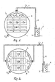
- FIG. 1 shows the arrangement of the pipe 6 with branches and manifold nozzle elements 8 for three standing upright next to each other on a lateral distance 2a aerated concrete blocks.
- An aerated concrete block 2a consists of a plurality of stacked aerated concrete blocks 2 stacked on top of one another and stacked in front of each other.
- the pipelines 6 and their branches and the nozzle elements 8 are located at the top in the so-called apex region of the autoclave 1.
- the pipelines 6 with branches and the nozzle elements 8 are arranged laterally of the three porous core blocks 2b, so that the aerated concrete blocks are sprayed laterally from two sides.
- the aerated concrete blocks 2b have been autoclaved lying.
- the Figures 1 and 2 show an autoclave system example and schematically.
- the outgoing of the spray or nozzle elements 8 arrows are the Schmelzeben Eatmaterial- represent that is sprayed.
- the negative pressure of, for example, minus 0.8 bar, preferably minus 0.5 to minus 0.7 bar, set.
- the control valve 7 is opened slowly. Due to the negative pressure in the autoclave, the heat storage material is sucked into the autoclave and through the pipe system 6 with the distributor nozzle elements 8 evenly on the uppermost layer the aerated concrete stones applied. It is important that the suction into the autoclave not abruptly, but slowly over a period of 5 to 30 minutes, preferably 10 to 15 minutes. In the same way thus the aerated concrete blocks are acted upon by the heat storage material.
- the penetration depth of the melt heat storage material can be influenced. It is preferred to achieve a penetration depth of at least one centimeter.
- the melt heat storage material is only located in a surface zone of the stone which is limited in depth and points in the masonry wall to the heat energy source.
- the fusion heat storage material is not located in the entire stone. This is advantageous since, in the event of a temperature or heat energy change in the interior of a room or on the outside of a building, the phase transformation processes of the heat storage material and thus the heat storage take place primarily in the surface region of the wall. The effect of the melt heat storage material is thus more effective than in the prior art, in which the melt heat storage material is distributed over the volume of the entire wall constructed with the stones.
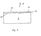
- FIG. 3 schematically shows a cross section through an aerated concrete block 2, the structure according to the invention in a single, from the surface 14 in the depth of a few centimeters to an irregularly limited transition zone 11 going to the unobstructed structure, surface area 13 is covered with a heat storage material 10.
- This surface 14 and thus also the surface region 13 are located in a wall, not shown, on the side of the aerated concrete block 2 or the wall acted upon by the heat energy 12.
Landscapes
- Chemical & Material Sciences (AREA)
- Engineering & Computer Science (AREA)
- Ceramic Engineering (AREA)
- Organic Chemistry (AREA)
- Materials Engineering (AREA)
- Structural Engineering (AREA)
- Oil, Petroleum & Natural Gas (AREA)
- Civil Engineering (AREA)
- Physics & Mathematics (AREA)
- Chemical Kinetics & Catalysis (AREA)
- Combustion & Propulsion (AREA)
- Thermal Sciences (AREA)
- Devices For Post-Treatments, Processing, Supply, Discharge, And Other Processes (AREA)
- Curing Cements, Concrete, And Artificial Stone (AREA)
- Building Environments (AREA)
Description
- Die Erfindung betrifft Porenbetonsteine sowie Verfahren und Vorrichtungen zur Herstellung der Porenbetonsteine.
- Porenbetonsteine im Sinne der vorliegenden Erfindung sind in einem Autoklaven aus üblichen, mindestens eine reaktionsfähige CaO- und mindestens eine reaktionsfähige SiO2-Komponente aufweisenden wässrigen Mischungen hydrothermal gehärtete, offenporige, geschnittene oder ungeschnittene Steine, deren wässrige Mischung vor der Autoklavierung mittels Treibporen oder durch Untermischung von Schaum porosiert worden ist. Unter Verwendung von Schaum hergestellte Porenbetonsteine werden auch Schaumbetonsteine genannt. Porenbetonsteine sind z.B. Plansteine, Planbauplatten, Wandelemente, Stürze, Dachplatten, Deckplatten oder dergleichen und großformatig und meist quaderförmig mit unterschiedlichen, in der Regel genormten Abmessungen. Porenbetonsteine weisen sehr gute Wärmedämmeigenschaften auf.
- Zweck der Erfindung ist, das Wärmespeichervermögen der Porenbetonsteine auf einfache und kostengünstige Weise zu erhöhen.
- Bekannt ist aus der
EP 1 752 509 B1 ein Verfahren zur Erhöhung der Wärmespeicherkapazität von Porenbetonsteinen, wobei in die Steine ein Schmelzwärmespeichermaterial, im Folgenden auch PCM genannt (PCM ist die Abkürzung für "Phase Change Material"), eingebracht wird und zwar in gekapselter Form als Mikrokapseln während der Herstellung der wässrigen Mischungen vor der Autoklavierung der Steine. Nachteilig ist, dass ein relativ teures Produkt, nämlich die Mikrokapseln, verwendet wird, und dass relativ große Mengen von Mikrokapseln zur Erzielung einer ausreichenden Speicherung von Wärmeenergie erforderlich sind. Vorteil der Mikrokapseln ist, dass sie in der Porenbetonproduktion auf einfache Weise der Mischung zugeführt werden können und durch die Verkapselung den Autoklavprozess überstehen können. - Weiterer Stand der Technik bezüglich thermischer Energiespeicherung in Bausteinen wird z. B. in den folgenden Druckschriften erläutert:
DE 103 29 583 A1 ,DE 199 29 861 A1 . - Insbesondere in der
DE 199 29 861 A1 sind zahlreiche Materialien aufgezählt und genannt, die verwendbar sind als Wärmeenergiespeichermaterialien (PCM), wobei dieser Stand der Technik lehrt, poröse Granulate oder Steine u.a. auch aus Porenbeton in PCM zu tränken und anschließend zu umhüllen, damit das PCM nicht entweichen kann. Die umhüllten Granulate werden als Zuschlagstoffe bei der Herstellung von Baumaterialien, z.B. Betonsteinen, verwendet. Die Tränkung mit PCM kann u.a. auch durch Anlegen eines Vakuums an das Trägermaterial beschleunigt werden, wobei darauf hingewiesen wird, dass sowohl das Trägermaterial als auch das PCM nicht über den Verdampfungspunkt des PCM erhitzt werden dürfen, damit das PCM nicht entweicht. - Aufgabe der Erfindung ist, einfach und kostengünstig Porenbetonsteine mit PCM bzw. Schmelzwärmespeichermaterial zu versehen und eine einfach aufgebaute Anlage zur Herstellung der Steine zu schaffen.
- Diese Aufgabe wird durch die Merkmale des Anspruchs 1, 6 und 13 gelöst. Vorteilhafte Weiterbildungen der Erfindung werden in den von diesen Ansprüchen abhängigen Ansprüchen gekennzeichnet.
- Nach der Erfindung wird zunächst eine übliche auf die Härtung des Porenbetonmaterials abgestimmte Autoklavreise mit Anfahr-, Halte- und Abfahrphase durchgeführt. Am Ende der Autoklavreise befindet sich der Autoklav auf Umgebungsdruck. Das Porenbetonmaterial hat eine Temperatur von ungefähr 100° C. Die Temperatur des Autoklaven und des Härtezeugs, darunter versteht man z.B. Härteroste, Härteböden und Härtewagen, liegt zu diesem Zeitpunkt meist zwischen 130 und 160° C.
- Anstatt den Autoklaven zu öffnen und die gehärteten Porenbetonsteine aus dem Autoklaven zu holen, wird erfindungsgemäß der Autoklav erneut evakuiert mit der vorhandenen Vakuumanlage. Je nach Leistungsfähigkeit der Vakuumanlage werden hierbei Unterdrücke zwischen z.B. minus 0,4 bis minus 0,8 bar, insbesondere zwischen minus 0,5 bis minus 0,6 bar, eingestellt. Durch die Evakuierung verdampft offenbar Wasser aus dem gehärteten Porenbetonmaterial im Oberflächenbereich autoklavseitiger Oberflächen der Steine und kühlt diesen Oberflächenbereich dabei auf Temperaturen von etwa 70° C bis 85° C ab. Diese Tatsache spielt bei der Erfindung eine überraschende Rolle, wie weiter unten erläutert wird.
- Unmittelbar nach dem Erreichen des gewünschten Unterdrucks im Autoklaven wird im Autoklaven auf eine autoklavseitige Oberfläche der gehärteten Porenbetonsteine flüssiges Schmelzwärmespeichermaterial, z.B. Paraffin oder Salzhydrate, fein verteilt über Düsen flächig aufgedüst bzw. aufgesprüht und zwar vorzugsweise über einen Zeitraum von 5 bis 30 Minuten, insbesondere von 10 bis 15 Minuten und zwar in Kombination mit der Höhe des eingestellten Unterdrucks derart, dass das Schmelzwärmespeichermaterial zweckmäßigerweise bis 5 cm, vorzugsweise zwischen 1 und 3 cm in die besprühte Oberflächenzone der Steine eindringt (autoklavseitige Oberfläche der Steine meint, dass es sich um Oberflächen handelt, die sich angrenzend an den Innenraum des Autoklaven zwischen Autoklavwandung und Porenbetonblock befinden).
- Die Dosiermenge an Schmelzwärmespeichermaterial ist abhängig von der gewünschten mit Schmelzwärmespeichermaterial belegten Dicke der Oberflächenzone und für das jeweilige Porenbetonmaterial empirisch zu ermitteln.
- Es ist überraschend, dass durch das erneute Anlegen eines Vakuums am Ende der Abfahrphase einer Autoklavreise das gehärtete Porenbetonmaterial im autoklavseitigen Oberflächenbereich so aufbereitet werden kann, dass eine optimale zonale Belegung mit Schmelzwärmespeichermaterial möglich ist. Überraschenderweise verteilt sich der Sprühnebel des Schmelzwärmespeichermaterials nicht im gesamten Autoklavenraum, sondern schlägt sich an den kühlsten Stellen im Autoklaven, nämlich auf der autoklavseitigen besprühten Oberfläche der Steine nieder. Warum das Schmelzwärmespeichermaterial in die Oberflächenbereiche eindringen kann, ist noch nicht geklärt, denn diese Oberflächenzonen bzw. -bereiche sind trotz des Vakuums vor dem Einbringen des Schmelzwärmespeichermaterials noch mit Wasser gefüllt, das aus dem Inneren der Steine stammt und die oberflächennahen Poren nachgefüllt hat, als durch das angelegte Vakuum diese Poren entleert wurden und das Wasser an die Autoklavenatmosphäre abgegeben wurde. Es findet offenbar beim Aufsprühen eine Verdrängung des Porenwassers statt, die relativ langsam vonstatten geht, weshalb nicht schlagartig besprüht werden darf, sondern langsam dosiert werden muss.
- Beim erfindungsgemäßen Verfahren hat das Vakuum nicht die Aufgabe, das Eindringen von Schmelzwärmespeichermaterial in die Poren des Porenbetonsteins zu beschleunigen, wie das beim Stand der Technik der Fall ist, sondern das Vakuum hat die Aufgabe, die Oberflächenzone aufnahmefähig für das Schmelzwärmespeichermaterial zu machen, indem zunächst Porenwasser verdrängt wird und anschließend Schmelzwärmespeichermaterial durch langsame Erhöhung des Druckes im Autoklaven, bewirkt durch das Einbringen des Schmelzwärmespeichermaterials mittels Luft beim Eindüsen, in Poren der Oberflächenzone eingedrückt wird, wobei möglicherweise vorhandenes, aus dem Innern des Porenbetonsteins nachgerücktes Wasser verdrängt wird, möglicherweise wieder zurück in das Innere des Steins.
- Durch das Schmelzwärmespeichermaterial werden die bauphysikalischen Eigenschaften des Porenbetonsteins nicht merklich verändert, was bedeutet, dass die Poren des Porenbetonmaterials nicht beeinträchtigend verstopft werden. Außerdem wird Schmelzwärmespeichermaterial in den Poren der Oberflächenzone des Porenbetonmaterials derart fest eingelagert, dass es nicht entweicht, z.B. im eingemauerten Zustand der Steine bei den Energiespeichervorgängen. Eine Umhüllung der mit Schmelzwärmespeichermaterial belegten Zonen, wie das der Stand der Technik lehrt, ist nicht erforderlich.
- Das Beladen der Oberflächenzone der Porenbetonsteine kann erleichtert werden, indem das Schmelzwärmespeichermaterial, z.B. in Form von Paraffin, nicht in flüssiger, sondern in gasförmiger Form in die Oberflächenzone eingebracht wird. Je nach chemischer Zusammensetzung liegen die Siedetemperaturen von Schmelzwärmespeichermaterial in Form von Paraffin bei 200 bis 350° C. Die Siedetemperatur von Paraffinen im Vakuum reduziert sich um 100 bis 150° C. Demgemäß ist zweckmäßig, Paraffin vor dem Aufsprühen auf mindestens 150 bis 250° C zu erwärmen und erst dann in den evakuierten Autoklaven strömen zu lassen. Dabei wird dass Paraffin im Vakuum verdampft und kann beim Niederschlagen auf der Porenbetonsteinoberfläche leichter in die Oberflächenzone eindringen. Das dampfförmige Paraffin kondensiert bevorzugt an den kältesten Stellen im Autoklaven. Dies sind, wie oben beschrieben, die autoklavseitigen Oberflächen des Porenbetonmaterials und nicht die Autoklavwandung oder das Härtezeug.
- Anhand der Zeichnung wird die Erfindung im Folgenden beispielhaft näher erläutert. Es zeigen:
- Figur 1
- schematisch eine erste Ausführungsform einer Autoklavanlage zur Durchführung des erfindungsgemäßen Verfahrens
- Figur 2
- schematisch eine weitere Ausführungsform einer Autoklavanlage zur Durchführung des erfindungsgemäßen Verfahrens
- Figur 3
- schematisch einen Querschnitt durch einen Porenbetonstein
- In einem herkömmlichen Produktionsautoklaven 1 befinden sich Porenbetonsteine 2. In der Nähe des Autoklaven 1 ist außerhalb ein Behälter 3 installiert, der mit einem Wärmespeichermaterial (PCM) 5 gefüllt ist. Dieser Behälter 3 ist mit dem Autoklaven 1 durch eine Rohrleitung 6 verbunden. Diese Rohrleitung 6 ist durch ein eingebautes Regelventil 7 absperrbar.
- Wenn mit der obersten Lage der Porenbetonsteine 2 die spätere Sichtfläche einer gemauerten Wand (Innen- oder Außenwand) erstellt werden soll, wird Schmelzwärmespeichermaterial nur auf die Oberfläche dieser Lage versprüht.
- Die Dosierung der Schmelzwärmespeichermaterial-Menge kann dabei über den Füllstand des Behälters 3 eingestellt werden. Der Füllstand im Behälter 3 ist z.B. so gewählt, dass die Schmelzwärmespeichermaterial-Menge für eine Behandlung pro Autoklav ausreicht. Der Behälter 3 wird dabei zweckmäßigerweise vollständig entleert. Vor der nächsten Behandlung wird der Behälter 3 wieder mit der entsprechenden Schmelzwärmespeichermaterial-Menge gefüllt. In einer zweckmäßigen Ausgestaltung kann der Behälter 3 mit einer Zusatzheizung 4 ausgerüstet werden, so dass das Schmelzwärmespeichermaterial im Behälter 3 erwärmt werden kann.
- Nach einer Ausführungsform der Erfindung wird das Schmelzwärmespeichermaterial bis kurz vor die Verdampfungs- bzw. Siedetemperatur erhitzt. Durch das Vakuum im Autoklaven verdampft das so erwärmte Schmelzwärmespeichermaterial beim Einsaugen. Durch das Verdampfen kann ein noch tieferes Eindringen des Schmelzwärmespeichermaterials in die Porenbetonsteinoberfläche erreicht werden.
-
Figur 1 zeigt die Anordnung der Rohrleitung 6 mit Verzweigungen und Verteilerdüsenelementen 8 für drei hochkant nebeneinander auf seitlichem Abstand 2a stehende Porenbetonblöcke. Ein Porenbetonblock 2a besteht aus mehreren aufeinander und voreinander gestapelten geschnittenen Porenbetonsteinen 2. Die Rohrleitungen 6 und deren Verzweigungen sowie die Düsenelemente 8 befinden sich oben im sogenannten Scheitelbereich des Autoklaven 1. - Bei der Ausführungsform nach
Figur 2 sind die Rohrleitungen 6 mit Verzweigungen und die Düsenelemente 8 seitlich der drei liegenden Porenbetonblöcke 2b angeordnet, so dass die Porenbetonblöcke seitlich von zwei Seiten besprüht werden. Dabei sind die Porenbetonblöcke 2b liegend autoklaviert worden. - Die
Figuren 1 und 2 zeigen eine Autoklavanlage beispielhaft und schematisch. Die von den Sprüh- oder Düsenelementen 8 abgehenden Pfeile sollen das Schmelzwärmespeichermaterial- darstellen, das versprüht wird. - Nach Abschluss einer üblichen Dampfhärtung wird der Autoklav nach dem erfindungsgemäßen Verfahren nicht entladen, sondern erneut evakuiert, über die vorhandene Rohrleitung 9 mit einer vorhandenen Vakuumanlage. Hierbei wird der Unterdruck von z.B. minus 0,8 bar, bevorzugt minus 0,5 bis minus 0,7 bar, eingestellt. Nach Erreichen des gewünschten Unterdrucks wird das Regelventil 7 langsam geöffnet. Durch den Unterdruck im Autoklaven wird das Schmelzwärmespeichermaterial dabei in den Autoklaven eingesaugt und über das Rohrleitungssystem 6 mit den Verteilerdüsenelementen 8 gleichmäßig auf die oberste Lage der Porenbetonsteine aufgebracht. Wichtig ist, dass das Einsaugen in den Autoklaven nicht schlagartig, sondern langsam über einen Zeitraum von 5 bis 30 Minuten, bevorzugt 10 bis 15 Minuten, erfolgt. In gleicher Weise werden somit die Porenbetonsteine mit dem Schmelzwärmespeichermaterial beaufschlagt. Durch dieses gesteuerte Verfahren kann die Eindringtiefe des Schmelzwärmespeichermaterials beeinflusst werden. Bevorzugt wird, eine Eindringtiefe von mindestens einem Zentimeter zu erreichen.
- Durch das erfindungsgemäße Verfahren wird gewährleistet, dass sich das Schmelzwärmespeichermaterial von der Oberfläche ausgehend nur in einer in der Tiefe begrenzten Oberflächenzone des Steins befindet, die in der gemauerten Wand zur Wärmeenergiequelle weist. Das Schmelzwärmespeichermaterial befindet sich nicht im gesamten Stein. Dies ist von Vorteil, da sich bei einem Temperatur- bzw. Wärmeenergiewechsel im Innern eines Raums oder außenseitig eines Gebäudes die Phasenumwandlungsvorgänge des Schmelzwärmespeichermaterials und damit die Wärmespeicherung in erster Linie im Oberflächenbereich der Wand abspielen. Die Wirkung des Schmelzwärmespeichermaterials ist somit effektiver als beim Stand der Technik, bei dem das Schmelzwärmespeichermaterial über das Volumen der gesamten mit den Steinen aufgebauten Wand verteilt ist.
-
Figur 3 zeigt schematisch einen Querschnitt durch einen Porenbetonstein 2, dessen Gefüge erfindungsgemäß in nur einem einzigen, von der Oberfläche 14 in die Tiefe von wenigen Zentimetern bis zu einer unregelmäßig begrenzten Übergangszone 11 zum unbelegten Gefüge gehenden, Oberflächenbereich 13 mit einem Schmelzwärmespeichermaterial 10 belegt ist. Diese Oberfläche 14 und damit auch der Oberflächenbereich 13 befinden sich in einer nicht dargestellten Wand auf der von der Wärmeenergie 12 beaufschlagten Seite des Porenbetonsteins 2 bzw. der Wand.
Claims (15)
- Porenbetonstein (2) mit üblicher Raumform und üblichen Abmessungen und einer Steinoberfläche (14), die dazu bestimmt ist, nach einem Einbau des Steins in eine Wandung eines Baukörpers, z.B. eines Gebäudes, dem Einfluss von von außen auf die Wandung wirkender alternierender Wärmeenergie ausgesetzt zu sein, aufweisend ein Gefüge aus Treibmakroporen oder aus einem Schaum resultierenden Makroporen, die von einem mit Mikroporen durchsetzten, aus Calciumsilikathydrat-Kristallphasen, insbesondere Tobermorit-Kristallphasen gebildetem Steggerüst umgeben sind,
dadurch gekennzeichnet, dass in den Poren eines von nur einer Steinoberfläche (14) des Porenbetonsteins (2) ausgehenden tiefenbegrenzten Oberflächenbereichs (13) von z.B. maximal 5 cm ein Schmelzwärmespeichermaterial enthalten ist. - Porenbetonstein nach Anspruch 1,
dadurch gekennzeichnet, dass das Schmelzwärmespeichermaterial bis in eine Tiefe von 1 bis 5 cm, insbesondere von 1 bis 3 cm enthalten ist. - Porenbetonstein nach Anspruch 1 und/oder 2,
dadurch gekennzeichnet, dass das Schmelzwärmespeichermaterial ein Paraffin ist und vorzugsweise in Mengen von 5 bis 20 Gew.-%, insbesondere von 10 bis 15 Gew.-% im Oberflächenbereich enthalten ist. - Porenbetonstein nach einem oder mehreren der Ansprüche 1 bis 3,
dadurch gekennzeichnet, dass die Steinoberfläche und der Steinoberflächenbereich darunter auf der ganzen Fläche und im gesamten Volumen mit Schmelzwärmespeichermaterial belegt sind. - Porenbetonstein nach Anspruch 4,
dadurch gekennzeichnet, dass das Schmelzwärmespeichermaterial homogen verteilt ist. - Verfahren zur Herstellung eines Porenbetonsteins nach einem oder mehreren der Ansprüche 1 bis 5, wobei in an sich bekannter Weise Porenbetonblöcke mit geschnittenen grünen Porenbetonsteinen in einem geschlossenen Autoklaven zumindest mit einer Anfahr-, einer Halte- und einer Abfahrphase gehärtet werden,
dadurch gekennzeichnet, dassa) nach der Abfahrphase im noch geschlossenen Autoklaven ein Unterdruck angelegt wird,b) flüssiges oder verdampfendes Schmelzwärmespeichermaterial von außerhalb des Autoklaven in den evakuierten Autoklaven eingebracht wird,c) das eingebrachte Schmelzwärmespeichermaterial auf nur eine autoklavseitige Oberfläche der gehärteten Steine aufgebracht wird. - Verfahren nach Anspruch 6,
dadurch gekennzeichnet, dass ein Unterdruck zwischen minus 0,4 bar und minus 0,8 bar, insbesondere zwischen minus 0,5 bar und minus 0,6 bar angelegt wird. - Verfahren nach Anspruch 6 und/oder 7,
dadurch gekennzeichnet, dass das Schmelzwärmespeichermaterial mittels des im Autoklaven anliegenden Unterdrucks in den Autoklaven gesaugt wird. - Verfahren nach einem oder mehreren der Ansprüche 6 bis 8,
dadurch gekennzeichnet, dass das Schmelzwärmespeichermaterial auf die Oberfläche gespritzt oder aufgesprüht oder aufgedüst wird. - Verfahren nach einem oder mehreren der Ansprüche 6 bis 9,
dadurch gekennzeichnet, dass als Schmelzwärmespeichermaterial ein flüssiges Paraffin oder Salzhydrat verwendet wird. - Verfahren nach einem oder mehreren der Ansprüche 6 bis 10,
dadurch gekennzeichnet, dass das Aufbringen des Schmelzwärmespeichermaterials langsam innerhalb von 5 bis 30, insbesondere von 10 bis 15 Minuten erfolgt. - Verfahren nach einem oder mehreren der Ansprüche 6 bis 11,
dadurch gekennzeichnet, dass das Schmelzwärmespeichermaterial vor dem Einbringen in den Autoklaven bis maximal zur Siedetemperatur erhitzt und in diesem Zustand in den Autoklaven eingebracht und zum Aufbringen auf die Oberfläche zum Verdampfen gebracht wird. - Autoklavanlage zum Härten von Porenbetonsteinen und zur Herstellung von Porenbetonsteinen nach einem oder mehreren der Ansprüche 1 bis 5 sowie zur Durchführung des Verfahrens nach einem oder mehreren der Ansprüche 6 bis 12, mit einem über einen Rohrstutzen (9) mit einer Vakuumeinrichtung in Verbindung stehenden Produktionsautoklaven (1) und mit mindestens einem außerhalb des Autoklaven (1) angeordneten, flüssiges Schmelzwärmespeichermaterial enthaltenden Behälter (3), wobei der Behälter (3) mit dem Autoklaven (1) über mindestens eine in den Autoklaven (1) führende Rohrleitung (6) in Verbindung steht, mit der Schmelzwärmespeichermaterial in den Autoklaven (1) geleitet werden kann, in der Rohrleitung (6) ein Regelventil (7) angeordnet ist und am freien Ende der Rohrleitung (6) im Autoklaven (1) Spritz-, Düsen- oder Sprühelemente (8) zum Aufspritzen, Aufdüsen oder Versprühen von Schmelzwärmespeichermaterial vorgesehen sind.
- Autoklavanlage nach Anspruch 13,
dadurch gekennzeichnet, dass der Behälter (3) mit einer Heizung (4) zur Erwärmung des Schmelzwärmespeichermaterials im Behälter ausgerüstet ist. - Autoklavanlage nach Anspruch 13 und/oder 14,
dadurch gekennzeichnet, dass die Spritz-, Düsen- oder Sprühelemente (8) im Scheitelbereich des Autoklaveninnenraums oder in den beiden Seitenbereichen des Autoklaveninnenraums angeordnet sind.
Applications Claiming Priority (1)
| Application Number | Priority Date | Filing Date | Title |
|---|---|---|---|
| DE200910041917 DE102009041917B3 (de) | 2009-09-17 | 2009-09-17 | Porenbetonsteine sowie Verfahren und die Verwendung einer Vorrichtung zu ihrer Hertstellung |
Publications (2)
| Publication Number | Publication Date |
|---|---|
| EP2308813A1 EP2308813A1 (de) | 2011-04-13 |
| EP2308813B1 true EP2308813B1 (de) | 2012-09-26 |
Family
ID=42937535
Family Applications (1)
| Application Number | Title | Priority Date | Filing Date |
|---|---|---|---|
| EP20100169045 Active EP2308813B1 (de) | 2009-09-17 | 2010-07-09 | Porenbetonsteine sowie Verfahren und Vorrichtung zu ihrer Herstellung |
Country Status (2)
| Country | Link |
|---|---|
| EP (1) | EP2308813B1 (de) |
| DE (1) | DE102009041917B3 (de) |
Families Citing this family (8)
| Publication number | Priority date | Publication date | Assignee | Title |
|---|---|---|---|---|
| DE202011002156U1 (de) * | 2011-01-31 | 2011-05-26 | Promat GmbH, 40878 | Latentwärmespeicher |
| CN103072200B (zh) * | 2013-02-20 | 2014-09-10 | 无锡职业技术学院 | 一种砼的水养护设备以及养护方法 |
| CN103290857A (zh) * | 2013-05-22 | 2013-09-11 | 国家电网公司 | 一种用于沙漠地区输电铁塔基础现浇混凝土养护方法 |
| PL236030B1 (pl) * | 2015-09-07 | 2020-11-30 | Politechnika Rzeszowska Im Ignacego Lukasiewicza | Przegroda budowlana izolacyjno-akumulacyjna i sposób jej wytwarzania |
| DE102016123739A1 (de) * | 2016-12-08 | 2018-06-14 | Technische Universität Darmstadt | Granulat zur Speicherung von Wärme und ein Verfahren zur Herstellung desselben |
| EP3652125A1 (de) | 2017-07-12 | 2020-05-20 | The European Union, represented by the European Commission | Herstellung von wärmeenergiespeichersystemen |
| CN108328110A (zh) * | 2018-01-05 | 2018-07-27 | 中山大学 | 一种多功能的岩土材料可视化便携养护箱 |
| CN113292357B (zh) * | 2021-05-28 | 2022-08-19 | 宁国华滋筑友建材科技有限公司 | 一种抗渗效果好的蒸压加气混凝土砌块aac-b配方及其蒸压养护装置 |
Family Cites Families (5)
| Publication number | Priority date | Publication date | Assignee | Title |
|---|---|---|---|---|
| DE3241798A1 (de) * | 1982-11-11 | 1984-05-17 | Will, Günther, Dr., 6100 Darmstadt | Herstellung von schall- und waermedaemmenden bauelementen |
| DE19929861A1 (de) * | 1999-06-30 | 2001-01-04 | Zae Bayern | Speicherverbundsysteme, bestehend aus Schmelzwärme-Speichermaterialien in porösen Trägermaterialien |
| DE29912086U1 (de) * | 1999-07-14 | 1999-09-23 | Boroske, Arnold, 50735 Köln | Autoklavenanlage und damit hergestellte Kalksandsteine |
| DE10329583A1 (de) | 2003-06-30 | 2005-02-03 | Behr Gmbh & Co. Kg | Werkstoff für Formteile |
| EP1752509B8 (de) | 2005-08-13 | 2007-10-03 | H+H Deutschland GmbH | Verfahren zur Erhöhung der Wärmespeicherkapazität von Bausteinen aus einem Kalzium-Silikat-Material sowie Baustein aus einem Kalzium-Silikat-Material |
-
2009
- 2009-09-17 DE DE200910041917 patent/DE102009041917B3/de not_active Expired - Fee Related
-
2010
- 2010-07-09 EP EP20100169045 patent/EP2308813B1/de active Active
Also Published As
| Publication number | Publication date |
|---|---|
| EP2308813A1 (de) | 2011-04-13 |
| DE102009041917B3 (de) | 2011-03-03 |
Similar Documents
| Publication | Publication Date | Title |
|---|---|---|
| DE102009041917B3 (de) | Porenbetonsteine sowie Verfahren und die Verwendung einer Vorrichtung zu ihrer Hertstellung | |
| DE102013007800B4 (de) | Trockenmörtelplatte sowie Verfahren und Verwendung einer Vorrichtung zu deren Herstellung | |
| EP0673733A2 (de) | Verfahren zur Herstellung einer porösen, mineralischen Leicht-Dämmplatte | |
| DE19929861A1 (de) | Speicherverbundsysteme, bestehend aus Schmelzwärme-Speichermaterialien in porösen Trägermaterialien | |
| EP0300241B1 (de) | Verfahren zur Herstellung und zur Verarbeitung von Reaktionskunststoff-Mischungen | |
| EP0793758A1 (de) | Verfahren zur feuchtigkeitsabdichtung von mauerwerk | |
| DE19706223A1 (de) | Wandsanierungsplatte für salzbelastete Mauern | |
| EP2724832B1 (de) | Verfahren zur herstellung eines mauersteins mit dämmfüllung | |
| EP0045047A1 (de) | Verfahren und Vorrichtung zur Herstellung eines wärmedämmenden Hohlblocksteins | |
| EP2765251B1 (de) | Plattenförmiger Wärmedämmverbund und Wärmedämmverbundareal, insbesondere Wärmedämmplattenareal, umfassend plattenförmigen Wärmedämmverbünde, sowie Verfahren zur Herstellung von Wärmedämmverbünden und Verwendung von Wärmedämmverbünden für die Wärmedämmung von Gebäuden | |
| DE3122087A1 (de) | "waermegedaemmter hohlblockstein sowie verfahren und vorrichtung zu dessen herstellung | |
| DE3932990C2 (de) | ||
| WO1980000232A1 (fr) | Procede de fabrication d'elements de construction isolants | |
| EP1172346A2 (de) | Verfahren und Vorrichtung zur Herstellung wärmeisolierender, unbrennbarer, plattenförmiger Formkörper | |
| DE1759696A1 (de) | Verfahren zur Herstellung von Daemmstoffen und daemmenden Bauteilen bzw.Bauelementen | |
| DE2532423A1 (de) | Verfahren zum herstellen wasserfester fertigbauteile | |
| EP2706158A1 (de) | Biozidhaltiges Verkleidungssystem | |
| WO1980000078A1 (fr) | Procede de fabrication de verre poreux et verre poreux obtenu par ce procede | |
| EP0035169B1 (de) | Formkörper aus geblähten Mineralien | |
| DE894519C (de) | Verfahren zur Herstellung von Formlingen aus Leichtbeton | |
| DE1033576B (de) | Anordnung zur maschinellen Herstellung von Betonwaren | |
| AT520113B1 (de) | Verfahren für das Herstellen eines Ziegels | |
| DE102005059781A1 (de) | Verfahren zur Herstellung von Verfüllsteinen und ein derartiger Verfüllstein | |
| EP3246490B1 (de) | Verfahren und vorrichtung zum einblasen von einblasdämmstoff in dämmstoffkammern von bauelementen | |
| AT210122B (de) | Zweischaliger Kaminformstein für den Hausbau und Verfahren zu seiner Herstellung |
Legal Events
| Date | Code | Title | Description |
|---|---|---|---|
| PUAI | Public reference made under article 153(3) epc to a published international application that has entered the european phase |
Free format text: ORIGINAL CODE: 0009012 |
|
| 17P | Request for examination filed |
Effective date: 20101215 |
|
| AK | Designated contracting states |
Kind code of ref document: A1 Designated state(s): AL AT BE BG CH CY CZ DE DK EE ES FI FR GB GR HR HU IE IS IT LI LT LU LV MC MK MT NL NO PL PT RO SE SI SK SM TR |
|
| AX | Request for extension of the european patent |
Extension state: BA ME RS |
|
| 17Q | First examination report despatched |
Effective date: 20110407 |
|
| GRAP | Despatch of communication of intention to grant a patent |
Free format text: ORIGINAL CODE: EPIDOSNIGR1 |
|
| GRAS | Grant fee paid |
Free format text: ORIGINAL CODE: EPIDOSNIGR3 |
|
| GRAA | (expected) grant |
Free format text: ORIGINAL CODE: 0009210 |
|
| AK | Designated contracting states |
Kind code of ref document: B1 Designated state(s): AL AT BE BG CH CY CZ DE DK EE ES FI FR GB GR HR HU IE IS IT LI LT LU LV MC MK MT NL NO PL PT RO SE SI SK SM TR |
|
| REG | Reference to a national code |
Ref country code: GB Ref legal event code: FG4D Free format text: NOT ENGLISH |
|
| REG | Reference to a national code |
Ref country code: CH Ref legal event code: EP |
|
| REG | Reference to a national code |
Ref country code: AT Ref legal event code: REF Ref document number: 576969 Country of ref document: AT Kind code of ref document: T Effective date: 20121015 |
|
| REG | Reference to a national code |
Ref country code: IE Ref legal event code: FG4D Free format text: LANGUAGE OF EP DOCUMENT: GERMAN |
|
| REG | Reference to a national code |
Ref country code: DE Ref legal event code: R096 Ref document number: 502010001347 Country of ref document: DE Effective date: 20121115 |
|
| PG25 | Lapsed in a contracting state [announced via postgrant information from national office to epo] |
Ref country code: NO Free format text: LAPSE BECAUSE OF FAILURE TO SUBMIT A TRANSLATION OF THE DESCRIPTION OR TO PAY THE FEE WITHIN THE PRESCRIBED TIME-LIMIT Effective date: 20121226 Ref country code: FI Free format text: LAPSE BECAUSE OF FAILURE TO SUBMIT A TRANSLATION OF THE DESCRIPTION OR TO PAY THE FEE WITHIN THE PRESCRIBED TIME-LIMIT Effective date: 20120926 Ref country code: LT Free format text: LAPSE BECAUSE OF FAILURE TO SUBMIT A TRANSLATION OF THE DESCRIPTION OR TO PAY THE FEE WITHIN THE PRESCRIBED TIME-LIMIT Effective date: 20120926 Ref country code: HR Free format text: LAPSE BECAUSE OF FAILURE TO SUBMIT A TRANSLATION OF THE DESCRIPTION OR TO PAY THE FEE WITHIN THE PRESCRIBED TIME-LIMIT Effective date: 20120926 |
|
| REG | Reference to a national code |
Ref country code: NL Ref legal event code: T3 |
|
| REG | Reference to a national code |
Ref country code: LT Ref legal event code: MG4D Effective date: 20120926 |
|
| PG25 | Lapsed in a contracting state [announced via postgrant information from national office to epo] |
Ref country code: SI Free format text: LAPSE BECAUSE OF FAILURE TO SUBMIT A TRANSLATION OF THE DESCRIPTION OR TO PAY THE FEE WITHIN THE PRESCRIBED TIME-LIMIT Effective date: 20120926 Ref country code: SE Free format text: LAPSE BECAUSE OF FAILURE TO SUBMIT A TRANSLATION OF THE DESCRIPTION OR TO PAY THE FEE WITHIN THE PRESCRIBED TIME-LIMIT Effective date: 20120926 Ref country code: LV Free format text: LAPSE BECAUSE OF FAILURE TO SUBMIT A TRANSLATION OF THE DESCRIPTION OR TO PAY THE FEE WITHIN THE PRESCRIBED TIME-LIMIT Effective date: 20120926 Ref country code: GR Free format text: LAPSE BECAUSE OF FAILURE TO SUBMIT A TRANSLATION OF THE DESCRIPTION OR TO PAY THE FEE WITHIN THE PRESCRIBED TIME-LIMIT Effective date: 20121227 |
|
| PG25 | Lapsed in a contracting state [announced via postgrant information from national office to epo] |
Ref country code: CZ Free format text: LAPSE BECAUSE OF FAILURE TO SUBMIT A TRANSLATION OF THE DESCRIPTION OR TO PAY THE FEE WITHIN THE PRESCRIBED TIME-LIMIT Effective date: 20120926 Ref country code: IS Free format text: LAPSE BECAUSE OF FAILURE TO SUBMIT A TRANSLATION OF THE DESCRIPTION OR TO PAY THE FEE WITHIN THE PRESCRIBED TIME-LIMIT Effective date: 20130126 Ref country code: EE Free format text: LAPSE BECAUSE OF FAILURE TO SUBMIT A TRANSLATION OF THE DESCRIPTION OR TO PAY THE FEE WITHIN THE PRESCRIBED TIME-LIMIT Effective date: 20120926 Ref country code: RO Free format text: LAPSE BECAUSE OF FAILURE TO SUBMIT A TRANSLATION OF THE DESCRIPTION OR TO PAY THE FEE WITHIN THE PRESCRIBED TIME-LIMIT Effective date: 20120926 Ref country code: ES Free format text: LAPSE BECAUSE OF FAILURE TO SUBMIT A TRANSLATION OF THE DESCRIPTION OR TO PAY THE FEE WITHIN THE PRESCRIBED TIME-LIMIT Effective date: 20130106 |
|
| PG25 | Lapsed in a contracting state [announced via postgrant information from national office to epo] |
Ref country code: PL Free format text: LAPSE BECAUSE OF FAILURE TO SUBMIT A TRANSLATION OF THE DESCRIPTION OR TO PAY THE FEE WITHIN THE PRESCRIBED TIME-LIMIT Effective date: 20120926 Ref country code: SK Free format text: LAPSE BECAUSE OF FAILURE TO SUBMIT A TRANSLATION OF THE DESCRIPTION OR TO PAY THE FEE WITHIN THE PRESCRIBED TIME-LIMIT Effective date: 20120926 Ref country code: PT Free format text: LAPSE BECAUSE OF FAILURE TO SUBMIT A TRANSLATION OF THE DESCRIPTION OR TO PAY THE FEE WITHIN THE PRESCRIBED TIME-LIMIT Effective date: 20130128 |
|
| PG25 | Lapsed in a contracting state [announced via postgrant information from national office to epo] |
Ref country code: BG Free format text: LAPSE BECAUSE OF FAILURE TO SUBMIT A TRANSLATION OF THE DESCRIPTION OR TO PAY THE FEE WITHIN THE PRESCRIBED TIME-LIMIT Effective date: 20121226 Ref country code: DK Free format text: LAPSE BECAUSE OF FAILURE TO SUBMIT A TRANSLATION OF THE DESCRIPTION OR TO PAY THE FEE WITHIN THE PRESCRIBED TIME-LIMIT Effective date: 20120926 |
|
| PLBE | No opposition filed within time limit |
Free format text: ORIGINAL CODE: 0009261 |
|
| STAA | Information on the status of an ep patent application or granted ep patent |
Free format text: STATUS: NO OPPOSITION FILED WITHIN TIME LIMIT |
|
| PG25 | Lapsed in a contracting state [announced via postgrant information from national office to epo] |
Ref country code: IT Free format text: LAPSE BECAUSE OF FAILURE TO SUBMIT A TRANSLATION OF THE DESCRIPTION OR TO PAY THE FEE WITHIN THE PRESCRIBED TIME-LIMIT Effective date: 20120926 |
|
| 26N | No opposition filed |
Effective date: 20130627 |
|
| REG | Reference to a national code |
Ref country code: DE Ref legal event code: R097 Ref document number: 502010001347 Country of ref document: DE Effective date: 20130627 |
|
| PG25 | Lapsed in a contracting state [announced via postgrant information from national office to epo] |
Ref country code: CY Free format text: LAPSE BECAUSE OF FAILURE TO SUBMIT A TRANSLATION OF THE DESCRIPTION OR TO PAY THE FEE WITHIN THE PRESCRIBED TIME-LIMIT Effective date: 20120926 |
|
| BERE | Be: lapsed |
Owner name: XELLA BAUSTOFFE G.M.B.H. Effective date: 20130731 |
|
| PG25 | Lapsed in a contracting state [announced via postgrant information from national office to epo] |
Ref country code: MC Free format text: LAPSE BECAUSE OF FAILURE TO SUBMIT A TRANSLATION OF THE DESCRIPTION OR TO PAY THE FEE WITHIN THE PRESCRIBED TIME-LIMIT Effective date: 20120926 |
|
| REG | Reference to a national code |
Ref country code: IE Ref legal event code: MM4A |
|
| REG | Reference to a national code |
Ref country code: FR Ref legal event code: ST Effective date: 20140331 |
|
| PG25 | Lapsed in a contracting state [announced via postgrant information from national office to epo] |
Ref country code: BE Free format text: LAPSE BECAUSE OF NON-PAYMENT OF DUE FEES Effective date: 20130731 |
|
| PG25 | Lapsed in a contracting state [announced via postgrant information from national office to epo] |
Ref country code: FR Free format text: LAPSE BECAUSE OF NON-PAYMENT OF DUE FEES Effective date: 20130731 |
|
| PG25 | Lapsed in a contracting state [announced via postgrant information from national office to epo] |
Ref country code: IE Free format text: LAPSE BECAUSE OF NON-PAYMENT OF DUE FEES Effective date: 20130709 |
|
| REG | Reference to a national code |
Ref country code: CH Ref legal event code: PL |
|
| GBPC | Gb: european patent ceased through non-payment of renewal fee |
Effective date: 20140709 |
|
| PG25 | Lapsed in a contracting state [announced via postgrant information from national office to epo] |
Ref country code: CH Free format text: LAPSE BECAUSE OF NON-PAYMENT OF DUE FEES Effective date: 20140731 Ref country code: LI Free format text: LAPSE BECAUSE OF NON-PAYMENT OF DUE FEES Effective date: 20140731 |
|
| PG25 | Lapsed in a contracting state [announced via postgrant information from national office to epo] |
Ref country code: SM Free format text: LAPSE BECAUSE OF FAILURE TO SUBMIT A TRANSLATION OF THE DESCRIPTION OR TO PAY THE FEE WITHIN THE PRESCRIBED TIME-LIMIT Effective date: 20120926 Ref country code: GB Free format text: LAPSE BECAUSE OF NON-PAYMENT OF DUE FEES Effective date: 20140709 |
|
| PG25 | Lapsed in a contracting state [announced via postgrant information from national office to epo] |
Ref country code: TR Free format text: LAPSE BECAUSE OF FAILURE TO SUBMIT A TRANSLATION OF THE DESCRIPTION OR TO PAY THE FEE WITHIN THE PRESCRIBED TIME-LIMIT Effective date: 20120926 Ref country code: MT Free format text: LAPSE BECAUSE OF FAILURE TO SUBMIT A TRANSLATION OF THE DESCRIPTION OR TO PAY THE FEE WITHIN THE PRESCRIBED TIME-LIMIT Effective date: 20120926 |
|
| PG25 | Lapsed in a contracting state [announced via postgrant information from national office to epo] |
Ref country code: HU Free format text: LAPSE BECAUSE OF FAILURE TO SUBMIT A TRANSLATION OF THE DESCRIPTION OR TO PAY THE FEE WITHIN THE PRESCRIBED TIME-LIMIT; INVALID AB INITIO Effective date: 20100709 Ref country code: MK Free format text: LAPSE BECAUSE OF FAILURE TO SUBMIT A TRANSLATION OF THE DESCRIPTION OR TO PAY THE FEE WITHIN THE PRESCRIBED TIME-LIMIT Effective date: 20120926 Ref country code: LU Free format text: LAPSE BECAUSE OF NON-PAYMENT OF DUE FEES Effective date: 20130709 |
|
| REG | Reference to a national code |
Ref country code: AT Ref legal event code: MM01 Ref document number: 576969 Country of ref document: AT Kind code of ref document: T Effective date: 20150709 |
|
| PG25 | Lapsed in a contracting state [announced via postgrant information from national office to epo] |
Ref country code: AT Free format text: LAPSE BECAUSE OF NON-PAYMENT OF DUE FEES Effective date: 20150709 |
|
| PG25 | Lapsed in a contracting state [announced via postgrant information from national office to epo] |
Ref country code: AL Free format text: LAPSE BECAUSE OF FAILURE TO SUBMIT A TRANSLATION OF THE DESCRIPTION OR TO PAY THE FEE WITHIN THE PRESCRIBED TIME-LIMIT Effective date: 20120926 |
|
| PGFP | Annual fee paid to national office [announced via postgrant information from national office to epo] |
Ref country code: DE Payment date: 20250929 Year of fee payment: 16 |
|
| PGFP | Annual fee paid to national office [announced via postgrant information from national office to epo] |
Ref country code: NL Payment date: 20260608 Year of fee payment: 17 |