EP2308527A1 - Extenseur urétéral pourvu de petite queue pour vessie - Google Patents
Extenseur urétéral pourvu de petite queue pour vessie Download PDFInfo
- Publication number
- EP2308527A1 EP2308527A1 EP10184665A EP10184665A EP2308527A1 EP 2308527 A1 EP2308527 A1 EP 2308527A1 EP 10184665 A EP10184665 A EP 10184665A EP 10184665 A EP10184665 A EP 10184665A EP 2308527 A1 EP2308527 A1 EP 2308527A1
- Authority
- EP
- European Patent Office
- Prior art keywords
- loop
- bladder
- distal region
- stent
- tail
- Prior art date
- Legal status (The legal status is an assumption and is not a legal conclusion. Google has not performed a legal analysis and makes no representation as to the accuracy of the status listed.)
- Withdrawn
Links
Images


Classifications
-
- A—HUMAN NECESSITIES
- A61—MEDICAL OR VETERINARY SCIENCE; HYGIENE
- A61F—FILTERS IMPLANTABLE INTO BLOOD VESSELS; PROSTHESES; DEVICES PROVIDING PATENCY TO, OR PREVENTING COLLAPSING OF, TUBULAR STRUCTURES OF THE BODY, e.g. STENTS; ORTHOPAEDIC, NURSING OR CONTRACEPTIVE DEVICES; FOMENTATION; TREATMENT OR PROTECTION OF EYES OR EARS; BANDAGES, DRESSINGS OR ABSORBENT PADS; FIRST-AID KITS
- A61F2/00—Filters implantable into blood vessels; Prostheses, i.e. artificial substitutes or replacements for parts of the body; Appliances for connecting them with the body; Devices providing patency to, or preventing collapsing of, tubular structures of the body, e.g. stents
- A61F2/82—Devices providing patency to, or preventing collapsing of, tubular structures of the body, e.g. stents
- A61F2/94—Stents retaining their form, i.e. not being deformable, after placement in the predetermined place
-
- A—HUMAN NECESSITIES
- A61—MEDICAL OR VETERINARY SCIENCE; HYGIENE
- A61M—DEVICES FOR INTRODUCING MEDIA INTO, OR ONTO, THE BODY; DEVICES FOR TRANSDUCING BODY MEDIA OR FOR TAKING MEDIA FROM THE BODY; DEVICES FOR PRODUCING OR ENDING SLEEP OR STUPOR
- A61M29/00—Dilators with or without means for introducing media, e.g. remedies
-
- A—HUMAN NECESSITIES
- A61—MEDICAL OR VETERINARY SCIENCE; HYGIENE
- A61M—DEVICES FOR INTRODUCING MEDIA INTO, OR ONTO, THE BODY; DEVICES FOR TRANSDUCING BODY MEDIA OR FOR TAKING MEDIA FROM THE BODY; DEVICES FOR PRODUCING OR ENDING SLEEP OR STUPOR
- A61M27/00—Drainage appliance for wounds or the like, i.e. wound drains, implanted drains
- A61M27/002—Implant devices for drainage of body fluids from one part of the body to another
- A61M27/008—Implant devices for drainage of body fluids from one part of the body to another pre-shaped, for use in the urethral or ureteral tract
-
- A—HUMAN NECESSITIES
- A61—MEDICAL OR VETERINARY SCIENCE; HYGIENE
- A61B—DIAGNOSIS; SURGERY; IDENTIFICATION
- A61B17/00—Surgical instruments, devices or methods, e.g. tourniquets
- A61B17/00234—Surgical instruments, devices or methods, e.g. tourniquets for minimally invasive surgery
- A61B2017/00292—Surgical instruments, devices or methods, e.g. tourniquets for minimally invasive surgery mounted on or guided by flexible, e.g. catheter-like, means
- A61B2017/003—Steerable
-
- A—HUMAN NECESSITIES
- A61—MEDICAL OR VETERINARY SCIENCE; HYGIENE
- A61B—DIAGNOSIS; SURGERY; IDENTIFICATION
- A61B18/00—Surgical instruments, devices or methods for transferring non-mechanical forms of energy to or from the body
- A61B2018/00053—Mechanical features of the instrument of device
- A61B2018/00107—Coatings on the energy applicator
- A61B2018/00148—Coatings on the energy applicator with metal
-
- A—HUMAN NECESSITIES
- A61—MEDICAL OR VETERINARY SCIENCE; HYGIENE
- A61B—DIAGNOSIS; SURGERY; IDENTIFICATION
- A61B18/00—Surgical instruments, devices or methods for transferring non-mechanical forms of energy to or from the body
- A61B2018/00053—Mechanical features of the instrument of device
- A61B2018/0016—Energy applicators arranged in a two- or three dimensional array
-
- A—HUMAN NECESSITIES
- A61—MEDICAL OR VETERINARY SCIENCE; HYGIENE
- A61B—DIAGNOSIS; SURGERY; IDENTIFICATION
- A61B18/00—Surgical instruments, devices or methods for transferring non-mechanical forms of energy to or from the body
- A61B2018/00636—Sensing and controlling the application of energy
- A61B2018/00773—Sensed parameters
- A61B2018/00791—Temperature
-
- A—HUMAN NECESSITIES
- A61—MEDICAL OR VETERINARY SCIENCE; HYGIENE
- A61F—FILTERS IMPLANTABLE INTO BLOOD VESSELS; PROSTHESES; DEVICES PROVIDING PATENCY TO, OR PREVENTING COLLAPSING OF, TUBULAR STRUCTURES OF THE BODY, e.g. STENTS; ORTHOPAEDIC, NURSING OR CONTRACEPTIVE DEVICES; FOMENTATION; TREATMENT OR PROTECTION OF EYES OR EARS; BANDAGES, DRESSINGS OR ABSORBENT PADS; FIRST-AID KITS
- A61F2/00—Filters implantable into blood vessels; Prostheses, i.e. artificial substitutes or replacements for parts of the body; Appliances for connecting them with the body; Devices providing patency to, or preventing collapsing of, tubular structures of the body, e.g. stents
- A61F2/02—Prostheses implantable into the body
- A61F2/04—Hollow or tubular parts of organs, e.g. bladders, tracheae, bronchi or bile ducts
- A61F2002/048—Ureters
-
- A—HUMAN NECESSITIES
- A61—MEDICAL OR VETERINARY SCIENCE; HYGIENE
- A61F—FILTERS IMPLANTABLE INTO BLOOD VESSELS; PROSTHESES; DEVICES PROVIDING PATENCY TO, OR PREVENTING COLLAPSING OF, TUBULAR STRUCTURES OF THE BODY, e.g. STENTS; ORTHOPAEDIC, NURSING OR CONTRACEPTIVE DEVICES; FOMENTATION; TREATMENT OR PROTECTION OF EYES OR EARS; BANDAGES, DRESSINGS OR ABSORBENT PADS; FIRST-AID KITS
- A61F2220/00—Fixations or connections for prostheses classified in groups A61F2/00 - A61F2/26 or A61F2/82 or A61F9/00 or A61F11/00 or subgroups thereof
- A61F2220/0008—Fixation appliances for connecting prostheses to the body
-
- A—HUMAN NECESSITIES
- A61—MEDICAL OR VETERINARY SCIENCE; HYGIENE
- A61F—FILTERS IMPLANTABLE INTO BLOOD VESSELS; PROSTHESES; DEVICES PROVIDING PATENCY TO, OR PREVENTING COLLAPSING OF, TUBULAR STRUCTURES OF THE BODY, e.g. STENTS; ORTHOPAEDIC, NURSING OR CONTRACEPTIVE DEVICES; FOMENTATION; TREATMENT OR PROTECTION OF EYES OR EARS; BANDAGES, DRESSINGS OR ABSORBENT PADS; FIRST-AID KITS
- A61F2220/00—Fixations or connections for prostheses classified in groups A61F2/00 - A61F2/26 or A61F2/82 or A61F9/00 or A61F11/00 or subgroups thereof
- A61F2220/0025—Connections or couplings between prosthetic parts, e.g. between modular parts; Connecting elements
- A61F2220/005—Connections or couplings between prosthetic parts, e.g. between modular parts; Connecting elements using adhesives
Definitions
- This application relates to ureteral stents.
- Ureteral stents are used to assist urinary drainage from the kidney to the bladder in patients with ureteral obstruction or injury, or to protect the integrity of the ureter in a variety of surgical manipulations. More specifically, stents may be used to treat or avoid ureter obstructions (such as ureteral stones or ureteral tumors) which disrupt the flow of urine from the kidneys to the bladder. Serious obstructions may cause urine to back up into the kidneys, threatening renal function. Ureteral stents may also be used after endoscopic inspection of the ureter.
- ureter obstructions such as ureteral stones or ureteral tumors
- Ureteral stents typically are tubular in shape, terminating in two opposing ends: a kidney (upper) end and a bladder (lower) end.
- the ends may be coiled in a pigtail or J-shape to prevent the upward or downward migration of the stent, e.g., with physiological movements.
- the kidney coil is designed to retrain the stent within the renal pelvis of the kidney and to prevent stent migration down the ureter.
- the bladder coil sits in the bladder and is designed to prevent stent migration upwards toward the kidney.
- the bladder coil is also used to aid in retrieval and removal of the stent.
- Ureteral stents may produce adverse effects including blood in the urine, a continual urge to urinate, strangury, and flank pain accompanying reflux of urine up the stent (e.g., when voiding) as pressure within the bladder is transmitted to the kidney.
- stents may cause or contribute to significant patient discomfort and serious medical problems.
- Figure 10 is a schematic drawing of the human urinary tract without a stent, showing the renal pelvis, the kidney, the ureter, and the ureteral orifices opening into the bladder.
- Figure 11 depicts a typical double-J stent 10 which comprises a small tube 12 which sits inside the urinary system and assists the flow of urine from the kidney (renal pelvis) to the bladder.
- Figure 12 depicts prior art indwelling ureteral stent 10 in position.
- Such stents are typically made of biocompatible plastic, coated plastic, or silicone material.
- Tube 12 typically varies in size from 4-8 fr. (mm in circumference), and it has multiple small holes throughout its length.
- a coiled shape pre-formed at each end 14 and 16 is designed to confine its movement within the urinary system, so that it will be maintained in the desired position.
- the upper (kidney) end 14 of the stent may be closed or tapered, depending on the method of insertion (e.g., the use of a guidewire).
- the tubular stent extends through the ureteral orifice 18a and into the bladder, fixing orifice 18a open, and thereby enhancing the opportunity for reflux.
- a monofilament thread 22 may be attached to the bladder end of the stent for removal, usually without cystoendoscopy.
- U.S. Patent No. 4,531,933 (“the '933 patent”) discloses a ureteral stent having helical coils at each end which are provided for preventing migration and expulsion.
- the invention features a thin flexible elongated tail member having an elongated external urine-transport surface.
- Urine flows along the outside surface of the structure, between that surface and the inside wall of the ureter. Without limiting our to a specific mechanism, it appears that urine may remain attached to, and flow along, the external urine transport surface.
- the external urine transport surface is sized and configured to extend along at least part of the ureter near the bladder, across the ureter/bladder junction, and from there through the ureteral opening into the bladder.
- the stent While most or all of the length of the stent may rely an such an external surface to assist flow, more typically the stent will also include an upper elongated tubular segment to transport urine along a significant portion of the upper ureter.
- the upper tubular segment is connected at its lower end to an elongated tail which has the above described external urine-transport surface.
- the upper tubular segment comprises: a) an upper region having at least a first opening; b) a lower region having at least a second opening to be positioned in the ureter outside the bladder, and c) a central lumen connecting the first opening to the second opening.
- the elongated tail is a thin flexible tail member or filament(s) extending from the lower region of the tubular segment at a point outside the bladder so as to receive urine from the second opening of the tubular segment and to transport urine along the ureter from the lower region of the tubular segment across the ureter/bladder junction and into the bladder.
- the upper region of the tubular segment is configured and sized for placement in the renal cavity.
- the elongated tail member comprises at least one (and more preferably at least two) thread filament(s).
- Two or more of the filaments may be configured in at least one filament loop, and, advantageously, the tail comprises no unlooped filaments, so that the tail is free from loose ends.
- the loop(s) can be made by joining the ends of a single filament, in which case the filament loop comprises a junction of individual filament ends, which junction typically is positioned at the point where tail joins to the elongated tubular segment.
- the tail is long enough to effectively prevent migration of the entire tail into the ureter, and the tail has a smaller outer diameter than the outer diameter of the tubular segment.
- the tubular stent segment is stiff enough to avoid crimping during insertion through the ureter, so that it can be inserted by typical procedures.
- the tail on the other hand, is extremely flexible (soft) in comparison to the tubular segment, and it has a much smaller diameter than the tubular segment to avoid discomfort, Even quite thin structures will provide urine transport, and the thinner and more flexible the tail is, the less likely it is to cause patient discomfort.
- the tail (and its connection to the rest of the stent) should have sufficient strength so the stent can be retrieved by locating the tail in the bladder and pulling on the tail to retrieve the stent from the kidney and ureter. Details of the tail size are discussed below.
- reinforcing materials e.g., sutures as described below
- the tail may be a suture, and the suture may be coated to avoid encrusting.
- the external urine-transport surface of the tail can be convex (circular or oval in section), concave or flat.
- the tail filament may be fluted.
- the tail may, but need not, include an accurately shaped anchor segment to control migration up the ureter.
- the tail may be either solid or hollow; even when hollow, it is not designed to transport a significant amount of urine internally.
- the tail may also be tapered.
- the upper region of the tubular segment may have a portion designed for placement in the renal cavity, which portion has enlarged diameter and/or straight sides and corners.
- the stent may include an extractor thread attached to the lower end of the elongated tail member.
- the tail may be molded in one piece with the tubular segment, or it may be made separately and attached to the bladder end region of the tubular segment at a point toward the kidney from the bladder end of the lower region of the tubular segment. In one specific embodiment, the tail is attached near or at the bladder end of the bladder end region of the tubular segment.
- the stent may include a suture souring the tail to the tubular segment, and the suture may be incorporated into the tail to impart strength to the tail so the tail may be used to retrieve the stent. If the tail includes a hollow lumen, the suture may be positioned inside that lumen.
- the suture may be attached to the tubular segment at a point in the bladder end region of the tubular segment, and the suture may extend from the point of attachment through an opening in the bladder end region to the central lumen of the tubular segment and from there to the hollow tail.
- at least the bladder end region of the tubular segment may include two lumens, a main urine-transporting lumen and a bladder lumen to encase the suture, so that the suture does not become encrusted.
- the outer diameter of the tubular segment can be tapered so that it decreases approaching its lower region.
- the lower region of the tubular segment may include multiple opening positioned, e.g., axially along include its length or radially around its circumference, or in other patterns.
- the outer diameter of the stent's tubular segment may decrease approaching the upper region.
- the maximum diameter may be at the site of the injury to encourage a sufficiently large inner diameter in the repaired structure, and the tubular segment's outer diameter may decrease moving away from that point of maximum diameter to sections of the normal ureter that are not in need of a broad support structure.
- the outer diameter of the upper end of the tubular segment will be greater than the outer diameter of the bladder end.
- the upper region may include multiple openings (inlets).
- the elongated external urine-transport surface is a continuous surface extending from the kidney to the bladder, e.g., it is the outer surface of a solid member extending from the kidney to the bladder.
- Another aspect of the invention features a method of introducing a ureteral stent (described above) into a patient, by (a) positioning the kidney end region of the tubular segment within the renal pelvis; and (b) positioning the elongated flexible member(s) in the bladder.
- Yet another aspect of the invention features a method of manufacturing a ureteral stent as described above.
- the method comprises: (a) providing a polymer pre-form having a tubular shape; (b) forming an elongated tubular stent segment from the polymer pre-form, and (c) providing tail member(s) at an end region of the tubular segment designed to be positioned toward the patient's bladder.
- the stent may be manufactured from a polymer form having a tubular shape by forcing the form onto a mandrel to produce the desired three dimensional shape (coils, etc.).
- the elongated tubular member(s) is attached to one end of the tubular member(s) using sutures as described above. Heat treatments to fuse the structures and/or standard adhesives may be used.
- the tubular member(s) and the elongated member constitute a one-piece stent.
- the use of relatively thin, flexible elongated member(s) to assist urine flow across the ureterovesical junction and into the bladder may reduce reflux and irritation and thereby reduce patient discomfort and medical problems associated with ureteral stents.
- a ureteral stent for assisting flow of urine within a patient's ureter and into the patient's bladder, comprises a thin flexible elongated member having an elongated external urine-transport surface sized and configured to transport urine along the surface within the ureter.
- the external urine transporting surface may be sized and configured to extend along at least part of the ureter, across the ureter/bladder junction, and from there through the ureteral opening into the bladder.
- the stent may further comprise an elongated tubular segment attached to said elongated member, the tubular segment comprising:
- the upper region may be configured and sized for placement in the renal cavity.
- the elongated member may be a tail comprising at least one thread filament.
- the tail may comprise multiple thread filaments.
- the tail may comprise at least one filament loop.
- the tail may comprise at least two filament loops.
- the tail may comprise no unlooped filaments, so that the tail is free from loose ends.
- the filament loop may comprise a junction of individual filament ends.
- junction of filament ends may be positioned at the point where the tail joins to the elongated tubular segment.
- the elongated member may be softer than the elongated tubular segment.
- the upper region may comprise a portion of enlarged diameter, designed for placement in the renal cavity.
- the upper region may have an external section having straight sides and corners.
- the tail may have a fluted filament.
- the stent may comprise an extractor thread attached to the lower end of the elongated member.
- the external urine-transport surface may be concave.
- the external urine-transport surface may be convex.
- the tubular segment may be stiff enough to avoid crimping during insertion through the ureter.
- the tail and its attachment to the tubular segment may be strong enough to permit retrieval of the stent from the kidney and ureter by locating the tail in the bladder and pulling on it.
- the tail may include an accurately shaped anchor segment to control migration up the ureter.
- the tail may be long enough to effectively prevent migration of the entire tail into the ureter.
- the tail may have a smaller outer diameter than the outer diameter of the tubular segment.
- the tail may be solid.
- At least part of the tail may be hollow.
- the outer diameter of the tubular segment may decrease approaching the bladder end region.
- the tubular member may include multiple openings along its length.
- the outer diameter of the tubular segment may decrease approaching the kidney end region of the stent.
- the kidney end region of the stent may include multiple openings.
- the tail may be attached to the bladder end region of the sent at a point toward the kidney with respect to the bladder end terminus of the bladder end region.
- a suture may secure the tail to the tubular segment.
- the suture may be incorporated in the tail to impart strength to the tail.
- the tail may comprise a hollow lumen and the suture may be positioned inside the hollow tail lumen.
- the tail may be hollow, and the suture may be attached to the tubular segment at a point toward the kidney with respect to the bladder end terminus of the bladder end region of the tubular segment, and the suture extends toward the bladder from the point of attachment through an opening in the bladder end region to the central lumen of the tubular segment and from there along the inside of the tail.
- At least the bladder end region of the tubular segment may comprise multiple lumens, one of the lumens enclosing the suture from the point of attachment to the tubular segment to the terminus of the bladder end region.
- the elongated external urine-transport surface may be a continuous surface extending from the kidney to the bladder.
- the elongated external surface may be the outer surface of a solid member extending from the kidney to the bladder.
- the tubular member and the elongated member may comprise a one-piece stent.
- the invention provides a method of introducing a ureteral stent into a patient, the stent comprises a) a thin flexible elongated member having an elongated external urine-transport surface sized and configured to transport urine along the surface within the ureter; and b) an elongated tubular segment attached to said elongated member, the tubular segment comprising: i) an upper region having at least a first opening, ii) a lower region having at least a second opening to be positioned in the ureter outside the bladder, and iii) a central lumen connecting the first opening to the second opening; the elongated member being a thin flexible tail extending from the lower region of the tubular segment at a point outside the bladder so as to receive urine from the second opening of the tubular segment and to transport urine from the second region across the ureter/bladder junction and into the bladder, the method comprising:
- ureteral stent 100 includes an elongated tubular body 130 connecting coil end 140 to straight end region 120.
- Tubular body 130 is designed to extend from the renal pelvis through the ureter to a terminus upstream of the bladder.
- Tail 110 is attached to straight end region 120, and tail 110 extends along the ureter, across the ureter/bladder junction and into the bladder.
- Coiled end region 140 is designed to be placed in the renal pelvis of the kidney.
- coiled end region 140 is shown with a pigtail helical coil although any shape that will retain the stent in place within the kidney will do.
- Coiled end region 140 includes several openings 125 placed along the wall of the tubular body; the openings may be arranged in various geometries (e.g., axial, circumferential, spiral), The entire tubular segment, including the region between the kidney and the bladder end regions, may include additional openings.
- the bladder end region 120 of the tubular stent segment is designed to terminate in the ureter, upstream of the bladder.
- the end region of stent 100 received in the kidney will be designated the kidney end and the opposite and of stent 100 toward the bladder will be termed the bladder end.
- Figure 2 is a cross-sectional view of stent 100 of Fig. 1 .
- elongated tubular body 130 has annular walls 250 having an inner and outer diameter.
- the outer diameter of tubular body 130 may be substantially uniform throughout much of the length of the tube, or it may taper from a relatively short region of larger diameter (the site of the repair, where there is a risk that the healing process will substantially restrict flow in the lumen) to a region of generally small diameter.
- the precise configuration may depend on the ureteral defect being corrected.
- uretaropelvic junction UPJ
- the stent keeps the ureter lumen open during the healing process, so that the inner diameter of the resulting healed structure is adequate.
- the section of the tubular segment at the defect is large enough to support growth of repair tissue having an adequate inner diameter.
- the outer diameter of the tubular segment may be far smaller, but with an inner diameter adequate for passage over a guidewire.
- the outer diameter of the bladder end region of the tubular segment typically is 2Fr.-12Fr.
- the outer diameter of tubular body 130 is greatest at the ureteropelvic junction obstruction but begins to taper approaching each end.
- the upper (kidney) portion of the tubular member 130 may be uniform in diameter, tapering just in the lower (bladder) portion.
- Tubular member 130 defines a central lumen or passageway 260, extending from kidney end region 140 to bladder end region 120.
- the inner diameter of lumen 260 is sufficient to permit passage over a guidewire.
- Tubular body 130 may also have openings 125 extending through its walls 250 to facilitate the flow of urine from the kidney into central lumen 260 and opening 127 to facilitate flow out of dental lumen 260.
- the outer diameter of elongated tubular body 130 tapers near bladder end region 120.
- the outer diameter of bladder end region 120 may be made as small as possible while maintaining the ability to pass over a guidewire.
- Elongated tubular body 130 may (but need not be) substantially straight in bladder end region 120, i.e, it does not coil or curve in the absence of external force.
- tail 110 is a single filament, it typically is thinner than even the smallest portion of bladder end region 120 of the tubular stent segment.
- Tail 110 may be attached at or near the end of region 120, and it extends from that attachment into the bladder.
- Tail 110 is either solid or hollow. It can be generally cylindrical in shape; alternatively, it can be fluted, concave (quarter-moon)-shaped or it may assume other shapes.
- the tail can have an outer diameter that is significantly less than the inner diameter of the ureter (typically 2-5mm) and no greater than the outer diameter of the tubular segment from which it extends.
- the tail diameter is less than 10Fr, and as low as a suture (about 0.5Fr).
- the tail diameter is between 2Fr. and 4Fr.
- the length of tail 110 is preferably between 1 and 100cm. In one embodiment, the tail is long enough so that at least a portion of it will remain in the bladder, and effectively the entire tail cannot migrate up into the ureter. Preferably the length is between 1 and 4ocm.
- Tail 110 is flexible and, upon application of force, can be curved, but also has memory such that when the force is removed, it is generally straight.
- Stent 100 including tail 110 and tube 130, may be a single unit.
- tail 110 can be a unified piece, expending from bladder end region 120 with no additional attachment means.
- tail 110 can be secured to elongated tube 130 or bladder end region 120 by physical or mechanical methods.
- a suture 415 is inserted through an opening 418 in the tubular member and then threaded through the lumen 417 of tubular member 430.
- tail 410 is a hollow member having suture 415 threaded through its inner lumpen 412.
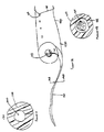
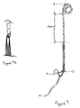
- Fig. 5 is a schematic of another stent 510.
- the kidney end A of the stent has a pre-formed memory bend, to coil 512 as shown. Kidney end A is larger and more rectangular to help prevent upward as well as downward stent migration. End A may be closed or tapered to accommodate various insertion techniques.
- diameter, lumpen size, perforations and materials are conventional.
- the lower end 514 of the tubular stent segment ends at B. The distance A--B could vary depending on the patient's anatomy.
- the stent is tapered (or at least smooth and constant in diameter).
- the portion of the upper segment 512 lying within the renal pelvis is expanded so that it is larger in section, and it may even be oval or rectangular in cross-section, to help prevent upward as well as downward stent migration.
- the kidney end of the stent may be closed and/or tapered to accommodate the desired insertion technique.
- the upper portion 512 is made of a relatively stiff material (among the materials currently used in ureteral stents), and it should be designed to effectively restrict the motion of the stent to prevent proximal as well as distal migration of the catheter during normal physiological activity (required because the lower pre-formed portion is deleted).
- the length of the straight portion of the upper segment ( Fig.
- the upper segment will vary with patient size and anatomy.
- the upper segment extends more than halfway down the ureter when in proper position.
- the lowest end of the upper segment ( Fig. 5A point B) should be tapered or beveled to facilitate withdrawal. Otherwise, the upper segment is a typical stent in diameter, materials and shape.
- the lower segment ( FIG. 5A point B to point C) consists of two or more (e.g four) monofilament, plastic coated or silicone coated threads (shown in section in Fig. 5B ) which extend from the lumen or sidewall of the lower end of the upper segment ( Fig. 5A point B) along ureter 513 into the bladder.
- These threads are extremely flexible, and their diameter is selected to maintain a passage for urine flow and yet drastically reduce bladder and ureteral irritation. By voiding distortion of the ureter wall, the threads may inhibit urinary reflux as well.
- the threads should be long enough to reach well into the bladder ( Fig. 5A point C), but not so long as to wash into the urethra with voiding.
- One thread 518 (or two or more threads in a loop) may be long enough to exit through the urethra ( Fig. 5A point B to point D) to permit ready removal by pulling (avoiding cystoendoscopy).
- These extended threads may also be used for stent exchange, in which a second catheter is exchanged for the catheter already in place. According to that procedure, these extended threads are captured with a snare that has been inserted through the central lumen of a second catheter. The snare is used to pull the threads through the lumen as the second catheter is advanced into the ureter. A guidewire is then inserted through the central lumen of the second catheter to the kidney (outside the first catheters tubular body). The first stent is then removed by pulling on the threads, leaving the guidewire in position for placement of a new stent using standard techniques.
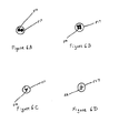
- Figs. 6A-6D are alternative cross sectional sketches (taken at the same location as Fig. 5B ) of some possible arrays of threads passing within the lower ureter 517. Multiple threads 516 (2 and 4, respectively) are shown in Figs. 6A and 6B .
- a substantially similar conduit could be achieved by fluted type cross sections in a single filament Figs. 6C and 6D ).
- the shapes of Figs. 6C and 6D could also be effective in reducing stiffness and hence irritability at the bladder end (i.e., lower segment), e.g., in a single filament design.
- Multiple threads may have the advantage of better surgical manipulability and superior comfort to the patient.
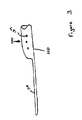
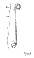
- Figs. 7 and 7A deal with: a) proximal or upward stent migration of either the entire stent or individual threads in the lower segment independent of upper segment movement; b) bunching of one or more threads within the ureter so as to obstruct flow or cause ureteral injury or knotting at the time of removal; and c) in multi-thread embodiments, discomfort and/or reduced drainage through the ureter resulting from the use of threads of different lengths.
- the upper segment need be only a single loop of conventional size because a change in the design of the lower segment (see latter discussion and Fig. 8 ) should prevent proximal migration.
- the upper segment ( Fig. 7 point A to point C) is constructed of a relatively firm material because, during insertion, the pusher tubing should be removed after the guidewire is removed. This means that there will be some drag on the threads during removal of the pusher tubing which could dislodge the stent if the coil ( Fig. 7 point A to point B, about 2.5 cm) does not provide adequate resistance.
- the coil may be tapered or closed depending on the insertion technique desired (i.e., over a previously placed guidewire.
- Fig. 7 point B to point C should have an approximate length of 12 cm. This is long enough to prevent dislocation of the upper segment in a large renal pelvis and short enough to end well above the point where the ureter crosses the common iliac vessels. At the iliac vessels, the ureter takes a fairly sharp turn and the threads will more easily follow the natural curves at this point. This design should reduce the inflammation that is normally seen in this region when a conventional double-J stent is left indwelling on a chronic basis.
- the junction of the upper and lower segments at Fig. 7 point C is important. See Fig. 7A , which enlarges this junction.
- the threads are attached to the upper segment in a manner that achieves the following goals: 1) the threads are securely attached to the upper segment and to each other (at least for a short distance of about 0.8 mm) so that their orientation to themselves is maintained (to the maintenance of lower end asymmetry); 2) the threads do not obstruct the lumen of the upper segment and they allow for the easy passage of a standard guidewire (e.g., 0.035 guidewire); 3) the transition diameters in this region closely preserve the 6F standard so that this point can pass in both directions smoothly throughout the instruments used for insertion and through the ureter; 4) there is no cause for a localized ureteral obstruction; and 5) there is an effective abutment for the pusher tubing.
- a standard guidewire e.g., 0.035 guidewire
- a good starting string diameter for a four string lower segment would be 0.020 inches.
- a simple monofilament nylon thread is an easy potential solution but may be too stiff.
- a more supple monofilament or woven thread with silicone or other coating may be required to achieve minimal irritability.
- the threads should be sufficiently resistant to compression so that tissue generated pressures cannot collapse the interspaces of the threads. See Fig. 8B , showing cross-sections of threads (left) which retain interstitial space under some modest compression and of threads (right) which are so soft that they compress into a plug with reduced interstitial space.
- These threads may have centimeter markings beginning at a point no more than 20 centimeters from point B ( Fig. 7 ) so that functional ureteral and total stent length may be noted.
- the portion of the lower segment which lies within the bladder when the stent is in proper anatomic position is important to both comfort and function.
- Proximal migration can be controlled by using asymmetrical length of the thread pairs, with one pair being 2 cm longer that the other pair, so that the fused junction of these threads tends to intersect with the ureteral orifice at and angle (e.g., -90°) with the stiffened length of 6 mm (see detail Fig. 8B ).
- the thread pairs will extend beyond the ureteral orifice ( Fig. 7 point D) by 1 cm at the short limb and 3 cm at the long limb.
- this lower segment configuration allows for considerable tolerance in sizing (unlike unsecured independent threads which must be selected to have a length so as to avoid upward migration of the thread through the ureter orifice) and a chosen length which is 1 cm shorter or 2-3 cm longer than the ideal length should be satisfactory.
- the threads should form a continuous loop of 3.5 cm length to prevent free ends from poking the bladder wall or prolapsing through the urethra. Buoyant threads may add to patient comfort, because they will float away from the trigone region of the bladder, where most of the sensory nerve fibers are located.
- a typical small gauge filament extraction thread may be attached to the longer limb of the thread pairs, which is a suitable pulling point for removal.
- a small diameter pusher tubing of 4--4.5 F should be used to aid insertion.
- Soft percuflex is near optimal for the lower segment, and firm or regular percuflex is used for the upper segment.
- the bladder end should be easily inserted using instruments, and it should prevent proximal migration of the stent.
- the design of Fig. 7 will avoid tangling and migration of the stent.
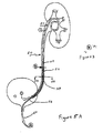
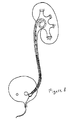
- soft percuflex for example, has good resistance to extreme flexion at small radii (e.g., even 0.020" diameter) so that a simple continuous loop extending from the junction of the supper and lower segments (see Fig. 9 ) may be adequate to prevent upward migration.
- the design of Fig. 9 also has the advantage of relative ease of manufacture and relative ease of insertion, as well as ease and comfort of removal.
- Fig. 9 shows such an alternative embodiment having a simple coil at the kidney end.
- the lower end is constructed of looped stringlike element with ends fused at the junction between the lower and the upper end. Therefore, there are an even number of string elements, with no free ends.
- Circle E in Fig. 9 represents an idealized depiction of the ureteral opening into the bladder. While not shown in Fig. 9 , the loops may be fused over a very short distance at the bladder end in order to prevent tangling of loops and to improve stent handling. Any conventional means of fusion may be used. Optionally, organization of the loops can be maintained by pre-placing them inside the pusher tubing using a long monofilament nylon loop tail, similar to those used for the non-invasive removal stents (i.e. without sensor endoscopy).
- stent placement is achieved by advancing the tubular stent segment over a guidewire in the ureter.
- a pushing catheter passels the tubular segment into the kidney, while maintaining the tail in the bladder.
- Other methods such as a stiff sheath can be used to position the stent. Once in position, the sheath can be removed.
- the tubular portion of the stent may be manufactured by extruding a tube according to known techniques.
- the elongated tail may be separately manufactured by conventional techniques and attached to the tubular portion, e.g., using biocompatible adhesive materials or heat.
- the stent may be made by injection molding the tube and the tail as a single piece, using a pin to create hollow segments.
- the stent may be manufactured from any of a number of biocompatible polymer commonly used inside the body, including polyurethane and polyethylene.
- the entire stent may be solid, so that urine is conveyed entirely on an external stent surface.
- the present subject-matter includes, inter alia, the following aspects:
Applications Claiming Priority (4)
| Application Number | Priority Date | Filing Date | Title |
|---|---|---|---|
| US625995P | 1995-11-07 | 1995-11-07 | |
| US2528496P | 1996-09-19 | 1996-09-19 | |
| EP96940309A EP0859644B1 (fr) | 1995-11-07 | 1996-11-06 | Extenseur ureteral pourvu de petite(s) queue(s) pour vessie |
| EP07004925A EP1792636B1 (fr) | 1995-11-07 | 1996-11-06 | Extenseur urétéral pourvu de petite queue pour vessie |
Related Parent Applications (2)
| Application Number | Title | Priority Date | Filing Date |
|---|---|---|---|
| EP96940309.6 Division | 1997-05-15 | ||
| EP07004925.9 Division | 2007-03-09 |
Publications (1)
| Publication Number | Publication Date |
|---|---|
| EP2308527A1 true EP2308527A1 (fr) | 2011-04-13 |
Family
ID=26675392
Family Applications (3)
| Application Number | Title | Priority Date | Filing Date |
|---|---|---|---|
| EP07004925A Expired - Lifetime EP1792636B1 (fr) | 1995-11-07 | 1996-11-06 | Extenseur urétéral pourvu de petite queue pour vessie |
| EP10184665A Withdrawn EP2308527A1 (fr) | 1995-11-07 | 1996-11-06 | Extenseur urétéral pourvu de petite queue pour vessie |
| EP96940309A Expired - Lifetime EP0859644B1 (fr) | 1995-11-07 | 1996-11-06 | Extenseur ureteral pourvu de petite(s) queue(s) pour vessie |
Family Applications Before (1)
| Application Number | Title | Priority Date | Filing Date |
|---|---|---|---|
| EP07004925A Expired - Lifetime EP1792636B1 (fr) | 1995-11-07 | 1996-11-06 | Extenseur urétéral pourvu de petite queue pour vessie |
Family Applications After (1)
| Application Number | Title | Priority Date | Filing Date |
|---|---|---|---|
| EP96940309A Expired - Lifetime EP0859644B1 (fr) | 1995-11-07 | 1996-11-06 | Extenseur ureteral pourvu de petite(s) queue(s) pour vessie |
Country Status (8)
| Country | Link |
|---|---|
| EP (3) | EP1792636B1 (fr) |
| JP (2) | JP4255513B2 (fr) |
| KR (1) | KR19990067352A (fr) |
| AU (1) | AU712420C (fr) |
| BR (1) | BR9611541A (fr) |
| CA (1) | CA2236437C (fr) |
| DE (2) | DE69638349D1 (fr) |
| WO (1) | WO1997017094A1 (fr) |
Cited By (1)
| Publication number | Priority date | Publication date | Assignee | Title |
|---|---|---|---|---|
| FR2999415A1 (fr) * | 2012-12-19 | 2014-06-20 | Benoit Vogt | Sonde endo-ureterale amelioree |
Families Citing this family (21)
| Publication number | Priority date | Publication date | Assignee | Title |
|---|---|---|---|---|
| US6676623B2 (en) * | 2001-05-04 | 2004-01-13 | Scimed Life Systems, Inc. | Drainage devices and methods |
| US6991614B2 (en) | 1995-11-07 | 2006-01-31 | Boston Scientific Scimed, Inc. | Ureteral stent for improved patient comfort |
| US6332892B1 (en) * | 1999-03-02 | 2001-12-25 | Scimed Life Systems, Inc. | Medical device with one or more helical coils |
| US6764519B2 (en) | 2000-05-26 | 2004-07-20 | Scimed Life Systems, Inc. | Ureteral stent |
| US6913625B2 (en) | 2002-03-07 | 2005-07-05 | Scimed Life Systems, Inc. | Ureteral stent |
| US8328877B2 (en) | 2002-03-19 | 2012-12-11 | Boston Scientific Scimed, Inc. | Stent retention element and related methods |
| US7485150B2 (en) | 2002-04-23 | 2009-02-03 | Boston Scientific Scimed, Inc. | Drainage devices and methods |
| KR100443299B1 (ko) * | 2002-05-16 | 2004-08-09 | 나공찬 | 방광 요관이행부에서의 방광요관역류 방지구 |
| US7357818B2 (en) | 2003-03-26 | 2008-04-15 | Boston Scientific Scimed, Inc. | Self-retaining stent |
| WO2006024489A2 (fr) | 2004-08-30 | 2006-03-09 | Interstitial Therapeutics | Procedes et compositions pour le traitement de la proliferation cellulaire |
| US7396366B2 (en) | 2005-05-11 | 2008-07-08 | Boston Scientific Scimed, Inc. | Ureteral stent with conforming retention structure |
| WO2010033592A1 (fr) * | 2008-09-16 | 2010-03-25 | C.R. Bard, Inc. | Stent |
| GB2464765A (en) * | 2008-10-30 | 2010-05-05 | Homerton University Hospital N | A ureteral stent having a sheath which retains a plurality of objects |
| WO2011123274A1 (fr) * | 2010-04-01 | 2011-10-06 | Xenolith Medical Ltd. | Dispositifs expansibles et procédés d'utilisation |
| WO2015154781A1 (fr) * | 2014-04-11 | 2015-10-15 | Coloplast A/S | Stent urétéral |
| US20170119559A1 (en) * | 2014-04-11 | 2017-05-04 | Coloplast A/S | A Ureteral Stent |
| WO2017192145A1 (fr) * | 2016-05-06 | 2017-11-09 | University Hospitals Health Systems, Inc. | Endoprothèse urétérale |
| WO2018085624A1 (fr) * | 2016-11-04 | 2018-05-11 | Boston Scientific Scimed, Inc. | Stent à extension commandée |
| WO2020086124A1 (fr) * | 2018-10-22 | 2020-04-30 | Askeland Eric | Endoprothèse de longueur variable |
| CN112425564A (zh) * | 2020-11-20 | 2021-03-02 | 云和县山区水产养殖技术研究所 | 一种提高甲鱼成活率及产量的养殖方法 |
| CN113303281B (zh) * | 2021-06-01 | 2022-04-01 | 广东省科学院动物研究所 | 一种具有景观丰容作用的绿海龟人工繁育喂食装置及其方法 |
Citations (9)
| Publication number | Priority date | Publication date | Assignee | Title |
|---|---|---|---|---|
| US4307723A (en) * | 1978-04-07 | 1981-12-29 | Medical Engineering Corporation | Externally grooved ureteral stent |
| US4531933A (en) | 1982-12-07 | 1985-07-30 | C. R. Bard, Inc. | Helical ureteral stent |
| DE3517813A1 (de) * | 1985-05-17 | 1986-11-20 | Jörg-Günter Dr.med. 3100 Celle Wiedeck | Transurethral plazierbare ureterschiene |
| US4671795A (en) * | 1984-11-19 | 1987-06-09 | Mulchin William L | Permanent/retrievable ureteral catheter |
| DE3740288C1 (en) * | 1987-11-27 | 1989-04-13 | Reuter Hans Joachim | Self-retaining catheter |
| EP0326908A2 (fr) * | 1988-01-30 | 1989-08-09 | B. Braun Melsungen AG | Appareil pour introduire un cathéter urétral |
| US4913683A (en) * | 1988-07-05 | 1990-04-03 | Medical Engineering Corporation | Infusion stent system |
| DE4103573A1 (de) * | 1991-02-06 | 1992-08-20 | Wilhelm Alexander Dr Huebner | Harnleiter-verweilkatheter |
| DE4134030A1 (de) * | 1991-10-15 | 1993-04-22 | Angiomed Ag | Vorrichtung zur ureterdrainage |
Family Cites Families (2)
| Publication number | Priority date | Publication date | Assignee | Title |
|---|---|---|---|---|
| US4212304A (en) * | 1978-04-07 | 1980-07-15 | Medical Engineering Corp. | Uretheral catheter stent |
| JPH06238007A (ja) * | 1993-02-14 | 1994-08-30 | Terumo Corp | 尿管ステント |
-
1996
- 1996-11-06 AU AU77227/96A patent/AU712420C/en not_active Expired
- 1996-11-06 WO PCT/US1996/017795 patent/WO1997017094A1/fr active IP Right Grant
- 1996-11-06 EP EP07004925A patent/EP1792636B1/fr not_active Expired - Lifetime
- 1996-11-06 EP EP10184665A patent/EP2308527A1/fr not_active Withdrawn
- 1996-11-06 BR BR9611541-6A patent/BR9611541A/pt not_active Application Discontinuation
- 1996-11-06 KR KR1019980703359A patent/KR19990067352A/ko not_active Application Discontinuation
- 1996-11-06 CA CA002236437A patent/CA2236437C/fr not_active Expired - Lifetime
- 1996-11-06 EP EP96940309A patent/EP0859644B1/fr not_active Expired - Lifetime
- 1996-11-06 DE DE69638349T patent/DE69638349D1/de not_active Expired - Lifetime
- 1996-11-06 JP JP51829897A patent/JP4255513B2/ja not_active Expired - Lifetime
- 1996-11-06 DE DE69637049T patent/DE69637049T2/de not_active Expired - Lifetime
-
2007
- 2007-01-17 JP JP2007008121A patent/JP4495736B2/ja not_active Expired - Lifetime
Patent Citations (9)
| Publication number | Priority date | Publication date | Assignee | Title |
|---|---|---|---|---|
| US4307723A (en) * | 1978-04-07 | 1981-12-29 | Medical Engineering Corporation | Externally grooved ureteral stent |
| US4531933A (en) | 1982-12-07 | 1985-07-30 | C. R. Bard, Inc. | Helical ureteral stent |
| US4671795A (en) * | 1984-11-19 | 1987-06-09 | Mulchin William L | Permanent/retrievable ureteral catheter |
| DE3517813A1 (de) * | 1985-05-17 | 1986-11-20 | Jörg-Günter Dr.med. 3100 Celle Wiedeck | Transurethral plazierbare ureterschiene |
| DE3740288C1 (en) * | 1987-11-27 | 1989-04-13 | Reuter Hans Joachim | Self-retaining catheter |
| EP0326908A2 (fr) * | 1988-01-30 | 1989-08-09 | B. Braun Melsungen AG | Appareil pour introduire un cathéter urétral |
| US4913683A (en) * | 1988-07-05 | 1990-04-03 | Medical Engineering Corporation | Infusion stent system |
| DE4103573A1 (de) * | 1991-02-06 | 1992-08-20 | Wilhelm Alexander Dr Huebner | Harnleiter-verweilkatheter |
| DE4134030A1 (de) * | 1991-10-15 | 1993-04-22 | Angiomed Ag | Vorrichtung zur ureterdrainage |
Cited By (4)
| Publication number | Priority date | Publication date | Assignee | Title |
|---|---|---|---|---|
| FR2999415A1 (fr) * | 2012-12-19 | 2014-06-20 | Benoit Vogt | Sonde endo-ureterale amelioree |
| FR2999416A1 (fr) * | 2012-12-19 | 2014-06-20 | Benoit Vogt | Sonde endo-ureterale amelioree |
| WO2014096264A1 (fr) | 2012-12-19 | 2014-06-26 | Vogt Benoît | Sonde endo-ureterale amelioree et methode de traitement de troubles urologiques |
| US9707383B2 (en) | 2012-12-19 | 2017-07-18 | Benoit VOGT | Ureteral stent and method for treating urological problems |
Also Published As
| Publication number | Publication date |
|---|---|
| JP4255513B2 (ja) | 2009-04-15 |
| BR9611541A (pt) | 1999-12-28 |
| AU712420B2 (en) | 1999-11-04 |
| DE69638349D1 (de) | 2011-05-12 |
| EP0859644A1 (fr) | 1998-08-26 |
| JP4495736B2 (ja) | 2010-07-07 |
| EP1792636A1 (fr) | 2007-06-06 |
| CA2236437A1 (fr) | 1997-05-15 |
| WO1997017094A1 (fr) | 1997-05-15 |
| JP2000500669A (ja) | 2000-01-25 |
| EP0859644B1 (fr) | 2007-04-25 |
| EP1792636B1 (fr) | 2011-03-30 |
| AU712420C (en) | 2003-10-02 |
| CA2236437C (fr) | 2003-10-14 |
| EP0859644A4 (fr) | 2000-05-17 |
| JP2007136216A (ja) | 2007-06-07 |
| KR19990067352A (ko) | 1999-08-16 |
| AU7722796A (en) | 1997-05-29 |
| DE69637049T2 (de) | 2007-12-27 |
| DE69637049D1 (de) | 2007-06-06 |
Similar Documents
| Publication | Publication Date | Title |
|---|---|---|
| US6945950B2 (en) | Ureteral stent with small bladder tail(s) | |
| US6991614B2 (en) | Ureteral stent for improved patient comfort | |
| JP4495736B2 (ja) | 小型膀胱尾部を備えている尿管ステント | |
| US7041139B2 (en) | Ureteral stents and related methods | |
| US6676623B2 (en) | Drainage devices and methods | |
| EP1158931B1 (fr) | Dispositif medical comportant au moins un enroulement helicoidal | |
| EP1496973B1 (fr) | Procedes et dispositifs de drainage | |
| EP2858710B1 (fr) | Endoprothèse urétérale destinée à être positionnée dans un rein et une vessie | |
| US20030195456A1 (en) | Ureteral stent with end-effector and related methods | |
| US20060206213A1 (en) | Facilitating drainage | |
| JPH0454459B2 (fr) | ||
| US20050240278A1 (en) | Stent improvements | |
| WO2001091668A1 (fr) | Endoprothese ureterale | |
| US20050240141A1 (en) | Stent kidney curl improvements | |
| US20100010478A1 (en) | Intraurethral catheter |
Legal Events
| Date | Code | Title | Description |
|---|---|---|---|
| PUAI | Public reference made under article 153(3) epc to a published international application that has entered the european phase |
Free format text: ORIGINAL CODE: 0009012 |
|
| 17P | Request for examination filed |
Effective date: 20100930 |
|
| AC | Divisional application: reference to earlier application |
Ref document number: 0859644 Country of ref document: EP Kind code of ref document: P Ref document number: 1792636 Country of ref document: EP Kind code of ref document: P |
|
| AK | Designated contracting states |
Kind code of ref document: A1 Designated state(s): BE DE DK FI FR GB IE IT NL |
|
| 17Q | First examination report despatched |
Effective date: 20111125 |
|
| RAP1 | Party data changed (applicant data changed or rights of an application transferred) |
Owner name: BOSTON SCIENTIFIC LIMITED |
|
| STAA | Information on the status of an ep patent application or granted ep patent |
Free format text: STATUS: THE APPLICATION HAS BEEN WITHDRAWN |
|
| 18W | Application withdrawn |
Effective date: 20170919 |