EP2306044A2 - Aggregatelager und ein Lagerkern dafür - Google Patents
Aggregatelager und ein Lagerkern dafür Download PDFInfo
- Publication number
- EP2306044A2 EP2306044A2 EP10009075A EP10009075A EP2306044A2 EP 2306044 A2 EP2306044 A2 EP 2306044A2 EP 10009075 A EP10009075 A EP 10009075A EP 10009075 A EP10009075 A EP 10009075A EP 2306044 A2 EP2306044 A2 EP 2306044A2
- Authority
- EP
- European Patent Office
- Prior art keywords
- bearing
- assembly
- stop
- bearing core
- sheath
- Prior art date
- Legal status (The legal status is an assumption and is not a legal conclusion. Google has not performed a legal analysis and makes no representation as to the accuracy of the status listed.)
- Granted
Links
Images




Classifications
-
- F—MECHANICAL ENGINEERING; LIGHTING; HEATING; WEAPONS; BLASTING
- F16—ENGINEERING ELEMENTS AND UNITS; GENERAL MEASURES FOR PRODUCING AND MAINTAINING EFFECTIVE FUNCTIONING OF MACHINES OR INSTALLATIONS; THERMAL INSULATION IN GENERAL
- F16F—SPRINGS; SHOCK-ABSORBERS; MEANS FOR DAMPING VIBRATION
- F16F13/00—Units comprising springs of the non-fluid type as well as vibration-dampers, shock-absorbers, or fluid springs
- F16F13/04—Units comprising springs of the non-fluid type as well as vibration-dampers, shock-absorbers, or fluid springs comprising both a plastics spring and a damper, e.g. a friction damper
- F16F13/06—Units comprising springs of the non-fluid type as well as vibration-dampers, shock-absorbers, or fluid springs comprising both a plastics spring and a damper, e.g. a friction damper the damper being a fluid damper, e.g. the plastics spring not forming a part of the wall of the fluid chamber of the damper
- F16F13/08—Units comprising springs of the non-fluid type as well as vibration-dampers, shock-absorbers, or fluid springs comprising both a plastics spring and a damper, e.g. a friction damper the damper being a fluid damper, e.g. the plastics spring not forming a part of the wall of the fluid chamber of the damper the plastics spring forming at least a part of the wall of the fluid chamber of the damper
- F16F13/10—Units comprising springs of the non-fluid type as well as vibration-dampers, shock-absorbers, or fluid springs comprising both a plastics spring and a damper, e.g. a friction damper the damper being a fluid damper, e.g. the plastics spring not forming a part of the wall of the fluid chamber of the damper the plastics spring forming at least a part of the wall of the fluid chamber of the damper the wall being at least in part formed by a flexible membrane or the like
- F16F13/101—Units comprising springs of the non-fluid type as well as vibration-dampers, shock-absorbers, or fluid springs comprising both a plastics spring and a damper, e.g. a friction damper the damper being a fluid damper, e.g. the plastics spring not forming a part of the wall of the fluid chamber of the damper the plastics spring forming at least a part of the wall of the fluid chamber of the damper the wall being at least in part formed by a flexible membrane or the like characterised by buffering features or stoppers
-
- F—MECHANICAL ENGINEERING; LIGHTING; HEATING; WEAPONS; BLASTING
- F16—ENGINEERING ELEMENTS AND UNITS; GENERAL MEASURES FOR PRODUCING AND MAINTAINING EFFECTIVE FUNCTIONING OF MACHINES OR INSTALLATIONS; THERMAL INSULATION IN GENERAL
- F16F—SPRINGS; SHOCK-ABSORBERS; MEANS FOR DAMPING VIBRATION
- F16F2230/00—Purpose; Design features
- F16F2230/48—Thermal insulation
Definitions
- the invention relates to an assembly bearing, comprising a bearing core and a support, which are supported by a spring body made of an elastomeric material to each other. Moreover, the invention relates to a bearing core for an assembly bearing,
- Assembly bearings and Lagerkeme are well known and designed for example as a hydraulic bearing for the storage of engines in motor vehicles. Due to the ever increasing demands on a good aerodynamics of motor vehicles and associated encapsulated and / or narrower engine compartments, the aggregate bearings used are exposed to high thermal loads.
- a bearing core of metallic material has a high strength and dimensional stability even when the assembly bearing is thermally highly stressed.
- Such a bearing core is advantageous if it has a stop for limiting extreme deflection movements of the bearing core with respect to the support.
- the disadvantage is that tied to the bearing core arranged spring body is acted upon by the good heat conductivity of the metallic bearing core with undesirably high temperatures. This often leads to at least reduced service life, if not to damage / destruction of the assembly storage.
- a bearing core of polymeric material in contrast, by its, based on metallic materials, better thermal insulation better protection of the elastomeric spring body from high temperatures.
- the bearing core has a stop for limiting extreme deflection movements and the stop also consists of a polymeric material, for example because it forms a one-piece part of the bearing core, the strength of this stop and, as a result, the service characteristics of the assembly bearing are less satisfactory.
- the invention is based on the object, an assembly bearing and a bearing core of the type mentioned in such a way that the consisting of an elastomeric material spring body through the bearing core is thermally insulated as well as possible and that the bearing core also has a sufficiently high strength when high transverse and tensile forces are introduced into the assembly bearing and these forces are limited by attacks of Lagerkems.
- an assembly warehouse comprising a bearing core with a sheath of a heat-insulating material and a support, wherein the sheath and the support are supported by a spring body made of an elastomeric material, wherein the bearing core has at least one stop made of a metallic material which is at least partially enclosed by the sheath and wherein the stop to limit extreme Auslenkterrorismen the Lagerkems can be applied relative to the support to a stop housing.
- the heat-insulating material is preferably formed by a polymeric material.
- the polymeric material may have a mineral filler for further improved thermal insulation.
- the filler may be formed by ground mica.
- the bearing core is formed as a multi-core, comprising the stopper of metallic material, which is enclosed by the sheath of polymeric material, wherein the elastomeric spring body comes into contact only with the sheath of polymeric material and not with a metallic material, the Target conflict heat insulation and thereby protection of the spring body on the one hand and strength / durability of the stop to limit extreme deflection movements on the other hand solved.
- the temperature inside the assembly bearing can be lowered by at least 10 ° C, based on assembly bearings in which the spring body touches a metallic bearing core.
- the existing of a metallic material stop which does not touch the spring body, has consistently good performance characteristics during a long service life.
- the strength of the attack can By dimensioning and / or material selection can be easily adapted to the particular circumstances of the application.
- the stop is completely covered by the sheath.
- the advantage here is that the stop is on the one hand well protected from environmental influences and on the other hand stop noises are reduced when the stop contacts the existing mostly of a metallic material stop housing to limit extreme deflection movements.
- the stop can be formed by a sheet metal part. Made of sheet metal stops can be easily and inexpensively manufactured, for example by deep drawing. In addition, the entire assembly warehouse is thus easy and inexpensive to produce. The encapsulation of metallic components with polymeric materials is well known and process reliable feasible.
- the stop and the spring body can be surrounded by the stopper housing substantially pot-shaped.
- the stop housing is frontally connected on the one hand to the support, for example by crimping, and the front side on the other hand, the stop housing on a central opening, which is penetrated by the bearing core.
- the limitation of extreme deflection movements takes place in the axial and radial direction in that the stop abuts against the stop housing. As a result, an undesirably high mechanical load of the elastomeric spring body is avoided; the service life and the performance characteristics of the assembly bearing are thereby improved.
- the support and the stop housing can be non-positively and / or positively connected to each other. Such joining techniques are also known and proven in the field of aggregates.
- the bearing core may have a fastening device for fastening an aggregate.
- the fastening device may be formed by a blind hole thread, a screw or a pin with transverse bore. This depends on the manner in which the unit to be stored can be attached to the bearing core.
- the fastening device may be at least partially covered by a mica heat shield on their sides facing the sheath.
- the mica heat shield may be formed by a mica disk and / or a mica pipe.
- the mica heat shield additionally protects the jacket against local temperature peaks.
- the assembly bearing described above may be formed as a hydraulic bearing, wherein the bearing core, the support and the spring body define a respectively filled with damping fluid working and compensation chamber, the working and compensation space separated by a partition and liquid-conductively connected to each other by a damping channel.
- the general structure described above can be modified as needed, for example by fitting nozzle cages adapted to the particular application in the dividing wall and / or by providing an additional absorber within the bearing in order to eliminate idle vibrations can.
- the bearing core according to the invention can be used in all known from the prior art Aggregatelagem.
- the invention relates to a bearing core for an assembly bearing, which has a sheath made of a heat-insulating material and at least one stop of a metallic material which is at least partially, preferably completely enclosed by the sheath.
- the heat-insulating material is, as described above, preferably a polymer.
- Such a bearing core can be used practically in all aggregate bearings, preferably in those which are exposed to high temperatures from the environment and have a stop housing for limiting extreme deflection movements. Due to the fact that the bearing core, with the exception of the abutment, consists of a polymeric material, the spring body and the interior of the assembly bearing are protected against an undesirably high heat transfer from the environment. The existing of a metallic material stop has a sufficiently high strength, even to survive a repeated impact on the stop housing without damage.
- FIGS. 1 to 6 in each case an embodiment of an assembly bearing according to the invention is shown, in which an inventive bearing core 1 is used.
- the bearing core 1 is in each case designed as MehrMechkem and comprises a sheath 2 made of a polymeric material and a stopper 5 made of a metallic material.
- the stopper 5 is formed in each case by a sheet metal part and in the FIGS. 1 and 6 partly, in the FIGS. 2 to 5 completely enclosed.
- the casing 2 is in any of the embodiments, a direct contact between the metallic stopper 5 and the spring body 4 made of elastomeric material; an undesirable in this case, material-related heat conduction from the stop 5 to the spring body 4 and into the interior of the assembly bearing is thereby avoided that the sheath 2 acts as a thermal insulation.
- the stopper 5 consists in the embodiments shown here of a metallic material which is thermally insulated from its surroundings by the sheath 2.
- the stopper 5 and the spring body 4 are enclosed by the cup-shaped stop housing 6, wherein the stopper housing 6 is flanged at its axially remote from the bearing core 1 end 18 to the corresponding end 19 of the support 3.
- the assembly bearing is designed as a hydraulic bearing and has a filled with damping fluid 10 Weg-11 and compensation chamber 12, which are separated by a partition wall 13 and liquid-conductively connected to each other through the damping channel 14.
- the hydraulic bearings are used in motor vehicles to support an internal combustion engine with respect to a chassis.
- FIG. 1 a first embodiment of an assembly bearing and a bearing core 1 is shown.
- the end face 17 of the stopper 5, which faces away axially from the working space 11, is flanged around a collar 20 of the fastening device 7
- the production of the bearing core 1 is such that the fastening device 7 and the stopper 5 are connected to a preassembled unit, wherein the preassemblable unit is then encapsulated with the polymeric material of the casing 2.
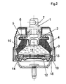
- FIG. 2 and FIG. 2a a second embodiment is shown in which the formed as a metallic deep drawn part stop 5 is completely enclosed by the casing 2.
- the fastening device 7 is encapsulated together with the stop 5 of the polymeric material of the casing 2.
- the fastening device 7 with respect to the sheath 2 by a mica disk 22 and a mica tube 23 is thermally insulated.
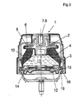
- FIG. 3 an embodiment is shown, similar to the embodiment of FIG. 2 , wherein the fastening element 7 is formed as a blind hole thread 8.
- FIG. 4 Is a further embodiment shown that differs from the embodiment FIG. 3 differs in that as a fastening element 7, a screw 9 is used.
- FIG. 5 an embodiment is shown, similar to the embodiment of FIG. 4 , The difference is that under the head of the screw 9, a disc 21 is arranged, via which the positive connection in the bearing core 1 is produced.
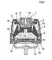
- FIG. 6 an embodiment is shown, with an intermediate ring 15 and an inner cable stop 16.
- an intermediate ring 15 can be combined with differently designed inner cable stops 16, so that, for example, fastening devices 7 in the form of a blind hole thread 8 accordingly FIG. 3 or in the form of a screw 9 accordingly FIG. 4 If necessary, they can be used.
Landscapes
- Engineering & Computer Science (AREA)
- General Engineering & Computer Science (AREA)
- Mechanical Engineering (AREA)
- Mounting Of Bearings Or Others (AREA)
- Support Of The Bearing (AREA)
- Sliding-Contact Bearings (AREA)
- Springs (AREA)
Abstract
Description
- Die Erfindung betrifft ein Aggregatelager, umfassend einen Lagerkern und ein Auflager, die durch einen Federkörper aus einem elastomeren Werkstoff aufeinander gestützt sind. Außerdem betrifft die Erfindung einen Lagerkern für ein Aggregatelager,
- Aggregatelager und Lagerkeme sind allgemein bekannt und beispielsweise als Hydrolager zur Lagerung von Motoren in Kraftfahrzeugen ausgebildet. Durch die immer höher werdenden Anforderungen an eine gute Aerodynamik von Kraftfahrzeugen und damit einhergehende gekapselte und/oder engere Motorräume sind die zur Anwendung gelangenden Aggregatelager hohen thermischen Belastungen ausgesetzt.
- Ein Lagerkern aus metallischem Werkstoff weist eine hohe Festigkeit und Formstabilität auch dann auf, wenn das Aggregatelager thermisch hochbelastet ist. Ein solcher Lagerkern ist von Vorteil, wenn dieser einen Anschlag zur Begrenzung extremer Auslenkbewegungen des Lagerkems bezogen auf das Auflager aufweist. Nachteilig ist jedoch, dass der am Lagerkern gebunden angeordnete Federkörper durch die gute Wärmefeitfähigkeit des metallischen Lagerkerns mit unerwünscht hohen Temperaturen beaufschlagt wird. Dies führt häufig zumindest zu verringerten Standzeiten, wenn nicht gar zu einer Beschädigung/Zerstörung des Aggregatelagers.
- Ein Lagerkern aus polymerem Werkstoff weist demgegenüber durch seine, bezogen auf metallische Werkstoffe, bessere Wärmeisolation einen besseren Schutz des elastomeren Federkörpers vor hohen Temperaturen auf. Insbesondere dann, wenn der Lagerkern einen Anschlag zur Begrenzung von extremen Auslenkbewegungen aufweist und der Anschlag ebenfalls aus einem polymeren Werkstoff besteht, weil er zum Beispiel einen einteiligen Bestandteil des Lagerkerns bildet, sind die Festigkeit dieses Anschlags und daraus resultierend die Gebrauchseigenschaften des Aggregatelagers wenig zufriedenstellend.
- Der Erfindung liegt die Aufgabe zu Grunde, ein Aggregatelager und einen Lagerkern der eingangs genannten Art derart weiterzuentwickeln, dass der aus einem elastomeren Werkstoff bestehende Federkörper durch den Lagerkern möglichst gut wärmeisoliert wird und dass der Lagerkern außerdem eine ausreichend große Festigkeit aufweist, wenn hohe Quer- und Zugkräfte in das Aggregatelager eingeleitet werden und diese Kräfte durch Anschläge des Lagerkems begrenzt werden.
- Diese Aufgabe wird erfindungsgemäß mit den Merkmalen der Ansprüche 1 und 15 gelöst. Auf vorteilhafte Ausgestaltungen nehmen die darauf jeweils rückbezogenen Unteransprüche Bezug.
- Zur Lösung der Aufgabe ist ein Aggregatelager vorgesehen, umfassend einen Lagerkern mit einer Ummantelung aus einem wärmeisolierenden Werkstoff und ein Auflager, wobei die Ummantelung und das Auflager durch einen Federkörper aus einem elastomeren Werkstoff aufeinander abgestützt sind, wobei der Lagerkern zumindest einen Anschlag aus einem metallischen Werkstoff aufweist, der zumindest teilweise von der Ummantelung umschlossen ist und wobei der Anschlag zur Begrenzung extremer Auslenkbewegungen des Lagerkems relativ zum Auflager an ein Anschlaggehäuse anlegbar ist.
- Der wärmeisolierende Werkstoff ist bevorzugt durch einen polymeren Werkstoff gebildet.
- Der polymere Werkstoff kann zur weiter verbesserten Wärmeisolierung einen mineralischen Füllstoff aufweisen.
- Der Füllstoff kann durch gemahlenen Glimmer gebildet sein.
- Dadurch, dass der Lagerkern als Mehrkörperkern ausgebildet ist, umfassend den Anschlag aus metallischem Werkstoff, der von der Ummantelung aus polymerem Werkstoff umschlossen ist, wobei der elastomere Federkörper nur mit der Ummantelung aus polymerem Werkstoff und nicht mit einem metallischen Werkstoff in Berührung kommt, wird der Zielkonflikt Wärmeisolation und dadurch Schutz des Federkörpers einerseits und Festigkeit/Dauerhaltbarkeit des Anschlags zur Begrenzung extremer Auslenkbewegungen andererseits gelöst.
- Durch die Ummantelung kann die Temperatur im Inneren des Aggregatelagers um zumindest 10°C gesenkt werden, bezogen auf Aggregatelager, bei denen der Federkörper einen metallischen Lagerkern berührt.
- Der aus einem metallischen Werkstoff bestehende Anschlag, der den Federkörper nicht berührt, weist gleichbleibend gute Gebrauchseigenschaften während einer langen Gebrauchsdauer auf. Die Festigkeit des Anschlags kann durch Dimensionierung und/oder Werkstoffauswahl problemlos an die jeweiligen Gegebenheiten des Anwendungsfalles angepasst werden.
- Bevorzugt ist es vorgesehen, dass der Anschlag von der Ummantelung vollständig ummantelt ist. Hierbei ist von Vorteil, dass der Anschlag einerseits gut vor Umgebungseinflüssen geschützt ist und andererseits Anschlaggeräusche reduziert sind, wenn der Anschlag das zumeist aus einem metallischen Werkstoff bestehende Anschlaggehäuse zur Begrenzung extremer Auslenkbewegungen berührt.
- Der Anschlag kann durch ein Blechteil gebildet sein. Aus Blech bestehende Anschläge können einfach und kostengünstig hergestellt werden, beispielsweise durch Tiefziehen. Außerdem ist das gesamte Aggregatelager dadurch einfach und kostengünstig herstellbar. Das Umspritzen metallischer Bauteile mit polymeren Werkstoffen ist allgemein bekannt und prozesssicher durchführbar.
- Der Anschlag und der Federkörper können vom Anschlaggehäuse im Wesentlichen topfförmig umschlossen sein. Das Anschlaggehäuse ist stirnseitig einerseits mit dem Auflager, zum Beispiel durch Bördeln, verbunden, und stirnseitig andererseits weist das Anschlaggehäuse eine zentrale Durchbrechung auf, die vom Lagerkern durchdrungen ist. Die Begrenzung extremer Auslenkbewegungen erfolgt in axialer und radialer Richtung dadurch, dass der Anschlag an das Anschlaggehäuse anschlägt. Dadurch wird eine unerwünscht hohe mechanische Belastung des elastomeren Federkörpers vermieden; die Gebrauchsdauer und die Gebrauchseigenschaften des Aggregatelagers werden dadurch verbessert.
- Das Auflager und das Anschlaggehäuse können kraft- und/oder formschlüssig miteinander verbunden sein. Derartige Fügetechniken sind auch im Bereich von Aggregatelagem bekannt und bewährt.
- Der Lagerkern kann eine Befestigungseinrichtung zur Befestigung eines Aggregats aufweisen. Die Befestigungseinrichtung kann durch ein Sacklochgewinde, eine Schraube oder einen Zapfen mit Querbohrung gebildet sein. Das ist davon abhängig, auf welche Art und Weise das zu lagernde Aggregat am Lagerkern befestigbar ist.
- Die Befestigungseinrichtung kann auf ihren der Ummantelung zugewandten Seiten zumindest teilweise von einem Glimmer-Wärmeschutzschild überdeckt sein.
- Das Glimmer-Wärmeschutzschild kann durch eine Glimmerscheibe und/oder ein Glimmerrohr gebildet sein.
- Durch das Glimmer-Wärmeschutzschild wird die Ummantelung zusätzlich vor lokalen Temperaturüberhöhungen geschützt.
- Das zuvor beschriebene Aggregatelager kann als Hydrolager ausgebildet sein, wobei der Lagerkern, das Auflager und der Federkörper einen jeweils mit Dämpfungsflüssigkeit gefüllten Arbeits- und Ausgleichsraum begrenzen, wobei der Arbeits- und Ausgleichsraum durch eine Trennwand voneinander getrennt und durch einen Dämpfungskanal flüssigkeitsleitend miteinander verbunden sind. Der zuvor beschriebene generelle Aufbau kann bedarfsweise modifiziert werden, z.B. dadurch, dass an den jeweiligen Anwendungsfall angepasste Düsenkäfige in der Trennwand montiert werden und/oder ein zusätzlicher Tilger innerhalb des Lagers vorgesehen wird, um Leerlaufschwingungen tilgen zu können. Der erfindungsgemäße Lagerkern kann bei allen aus dem Stand der Technik bekannten Aggregatelagem zur Anwendung gelangen.
- Außerdem betrifft die Erfindung einen Lagerkern für ein Aggregatelager, der eine Ummantelung aus einem wärmeisolierenden Werkstoff und zumindest einen Anschlag aus einem metallischen Werkstoff aufweist der von der Ummantelung zumindest teilweise, bevorzugt vollständig umschlossen ist. Der wärmeisolierende Werkstoff ist, wie zuvor beschrieben, bevorzugt ein Polymer. Ein solcher Lagerkern kann praktisch in allen Aggregatelagern zur Anwendung gelangen, bevorzugt in solchen, die hohen Temperaturen aus der Umgebung ausgesetzt sind und ein Anschlaggehäuse zur Begrenzung extremer Auslenkbewegungen aufweisen. Dadurch, dass der Lagerkern, mit Ausnahme des Anschlags, aus einem polymeren Werkstoff besteht, sind der Federkörper und das Innere des Aggregatelagers vor einer unerwünscht hohen Wärmeübertragung aus der Umgebung geschützt. Der aus einem metallischen Werkstoff bestehende Anschlag weist eine ausreichend hohe Festigkeit auf, auch um ein wiederholtes Anschlagen am Anschlaggehäuse unbeschadet zu überstehen.
- In den
Figuren 1 bis 6 ist jeweils ein Ausführungsbeispiel eines erfindungsgemäßen Aggregatelager mit erfindungsgemäßem Lagerkern gezeigt. Die Figuren zeigen in schematischer Darstellung: - Figur 1
- ein erstes Ausführungsbeispiel mit einem Anschlag, der als stirnseitig eingebördeltes Blechteil ausgebildet ist,
- Figur 2
- ein zweites Ausführungsbeispiel, bei dem der Anschlag aus einem metallischen Tiefziehtteil besteht, das vollständig von der polymeren Ummantelung des Lagerkerns ummantelt ist,
- Figur 2a
- das zweite Ausführungsbeispiel aus
Figur 2 , bei dem die Befestigungseinrichtung gegenüber der Ummantelung durch eine Glimmerscheibe und ein Glimmerrohr wärmeisoliert ist, - Figur 3
- ein drittes Ausführungsbeispiel, ähnlich dem Ausführungsbeispiel aus
Figur 2 , wobei die Befestigungseinrichtung als Sacklochgewinde ausgebildet ist, - Figur 4
- ein viertes Ausführungsbeispiel, ähnlich dem Ausführungsbeispiel aus
Figur 3 , wobei die Befestigungseinrichtung als Schraube ausgebildet ist, - Figur 5
- ein fünftes Ausführungsbeispiel, ähnlich dem Ausführungsbeispiel aus
Figur 4 , wobei unter dem Schraubenkopf eine zusätzliche Scheibe angeordnet ist, - Figur 6
- ein sechstes Ausführungsbeispiel mit einem Zwischenring und einem inneren Zuganschlag.
- In den
Figuren 1 bis 6 ist jeweils ein Ausführungsbeispiel eines erfindungsgemäßen Aggregatelagers gezeigt, in dem ein erfindungsgemäßer Lagerkern 1 zur Anwendung gelangt. - Der Lagerkern 1 ist jeweils als Mehrkörperkem ausgebildet und umfasst eine Ummantelung 2 aus einem polymeren Werkstoff sowie einen Anschlag 5 aus einem metallischen Werkstoff. Der Anschlag 5 ist jeweils durch ein Blechteil gebildet und in den
Figuren 1 und6 teilweise, in denFiguren 2 bis 5 vollständig umschlossen. Durch die Ummantelung 2 besteht in keinem der Ausführungsbeispiele ein unmittelbarer Kontakt zwischen dem metallischen Anschlag 5 und dem Federkörper 4 aus elastomerem Werkstoff; eine in diesem Fall unerwünscht gute, materialbedingte Wärmeleitung vom Anschlag 5 zum Federkörper 4 und ins Innere des Aggregatelagers wird dadurch vermieden, dass die Ummantelung 2 als Wärmeisolation fungiert. - Zur Begrenzung extremer Auslenkbewegungen zwischen dem Lagerkern 1 und dem Auflager 3 in axialer und/oder radialer Richtung ist der Anschlag 5 vorgesehen, der eine ausreichend große Festigkeit aufweist. Ein Anschlag aus einem polymeren Werkstoff wäre nicht ausreichend fest. Der Anschlag 5 besteht in den hier gezeigten Ausführungsbeispielen aus einem metallischen Werkstoff, der gegenüber seiner Umgebung durch die Ummantelung 2 wärmeisoliert ist.
- Der Anschlag 5 und der Federkörper 4 sind von dem topfförmig ausgebildeten Anschlaggehäuse 6 umschlossen, wobei das Anschlaggehäuse 6 an seinem dem Lagerkern 1 axial abgewandten Ende 18 um das entsprechende Ende 19 des Auflagers 3 umgebördelt ist.
- In jedem der Ausführungsbeispiele ist das Aggregatelager als Hydrolager ausgebildet und weist einen mit Dämpfungsflüssigkeit 10 gefüllten Arbeits-11 und Ausgleichsraum 12 auf, die durch eine Trennwand 13 getrennt und durch den Dämpfungskanal 14 flüssigkeitsleitend miteinander verbunden sind.
- Die Hydrolager gelangen zum Beispiel in Kraftfahrzeugen zur Anwendung, um eine Verbrennungskraftmaschine gegenüber einem Chassis zu lagern.
- In
Figur 1 ist ein erstes Ausführungsbeispiel eines Aggregatelagers und eines Lagerkerns 1 gezeigt. Die Stirnseite 17 des Anschlags 5, die dem Arbeitsraum 11 axial abgewandt ist, ist um einen Bund 20 der Befestigungseinrichtung 7 umgebördelt - Die Herstellung des Lagerkems 1 erfolgt derart, dass die Befestigungseinrichtung 7 und der Anschlag 5 zu einer vormontierbaren Einheit verbunden werden, wobei die vormontierbare Einheit anschließend mit dem polymeren Werkstoff der Ummantelung 2 umspritzt wird.
- In
Figur 2 undFigur 2a ist ein zweites Ausführungsbeispiel gezeigt, bei dem der als metallisches Tiefziehtteil ausgebildete Anschlag 5 von der Ummantelung 2 vollständig umschlossen ist. Die Befestigungseinrichtung 7 wird zusammen mit dem Anschlag 5 vom polymeren Werkstoff der Ummantelung 2 umspritzt. - In
Figur 2a ist die Befestigungseinrichtung 7 gegenüber der Ummantelung 2 durch eine Glimmerscheibe 22 und ein Glimmerrohr 23 wärmeisoliert. - In
Figur 3 ist ein Ausführungsbeispiel gezeigt, ähnlich dem Ausführungsbeispiel ausFigur 2 , wobei das Befestigungselement 7 als Sacklochgewinde 8 ausgebildet ist. - In
Figur 4 Ist ein weiteres Ausführungsbeispiel gezeigt, dass sich vom Ausführungsbeispiel ausFigur 3 dadurch unterscheidet, das als Befestigungselement 7 eine Schraube 9 zur Anwendung gelangt. - In
Figur 5 ist ein Ausführungsbeispiel gezeigt, ähnlich dem Ausführungsbeispiel ausFigur 4 . Der Unterschied besteht darin, dass unter dem Kopf der Schraube 9 eine Scheibe 21 angeordnet ist, über die der Formschluss im Lagerkern 1 hergestellt wird. - In
Figur 6 ist ein Ausführungsbeispiel gezeigt, mit einem Zwischenring 15 und einem inneren Zuganschlag 16. Durch eine solche Ausführung besteht die Möglichkeit eines Baukastensystems. Unterschiedlich gestaltete Zwischenringe 15 können mit unterschiedlich gestalteten inneren Zuganschlägen 16 kombiniert werden, so dass beispielsweise Befestigungseinrichtungen 7 in Form eines Sacklochgewindes 8 entsprechendFigur 3 oder in Form einer Schraube 9 entsprechendFigur 4 bedarfsweise zur Anwendung gelangen können.
Claims (20)
- Aggregatelager, umfassend einen Lagerkern (1) mit einer Ummantelung (2) aus einem wärmeisolierenden Werkstoff und ein Auflager (3), wobei die Ummantelung (2) und das Auflager (3) durch einen Federkörper (4) aus einem elastomeren Werkstoff aufeinander abgestützt sind, wobei der Lagerkern (1) zumindest einen Anschlag (5) aus einem metallischen Werkstoff aufweist, der zumindest teilweise von der Ummantelung (2) umschlossen ist und wobei der Anschlag (5) zur Begrenzung extremer Auslenkbewegungen des Lagerkerns (1) relativ zum Auflager (3) an ein Anschlaggehäuse (6) anlegbar ist
- Aggregatelager nach Anspruch 1, dadurch gekennzeichnet, dass der wärmeisolierende Werkstoff durch einen polymeren Werkstoff gebildet ist.
- Aggregatelager nach Anspruch 2, dadurch gekennzeichnet, dass der polymere Werkstoff einen mineralischen Füllstoff aufweist.
- Aggregatelager nach Anspruch 3, dadurch gekennzeichnet, dass der Füllstoff durch gemahlenen Glimmer gebildet ist.
- Aggregatelager nach einem der Ansprüche 1 bis 4, dadurch gekennzeichnet, dass der Anschlag (5) von der Ummantelung (2) vollständig ummantelt ist.
- Aggregatelager nach einem der Ansprüche 1 bis 5, dadurch gekennzeichnet, dass die Ummantelung (2) aus Polyamid 6.6, gefüllt mit Glasfasern besteht und eine Dicke von zumindest 5 mm aufweist.
- Aggregatelager nach einem der Ansprüche 1 bis 6, dadurch gekennzeichnet, dass der Anschlag (5) durch ein Blechteil gebildet ist
- Aggregatelager nach einem der Ansprüche 1 bis 7, dadurch gekennzeichnet, dass der Anschlag (5) und der Federkörper (4) vom Anschlaggehäuse (6) im Wesentlichen topfförmig umschlossen sind.
- Aggregatelager nach einem der Ansprüche 1 bis 8, dadurch gekennzeichnet, dass das Anschlaggehäuse (6) und das Auflager (3) kraft- und/oder formschlüssig miteinander verbunden sind,
- Aggregatelager nach einem der Ansprüche 1 bis 9, dadurch gekennzeichnet, dass der Lagerkern (1) eine Befestigungseinrichtung (7) zur Befestigung eines Aggregats aufweist.
- Aggregatelager nach Anspruch 10, dadurch gekennzeichnet, dass die Befestigungseinrichtung (7) durch ein Sacklochgewinde, eine Schraube oder einen Zapfen mit Querbohrung gebildet ist.
- Aggregatelager nach einem der Ansprüche 10 oder 11, dadurch gekennzeichnet, dass die Befestigungseinrichtung (7) auf ihren der Ummantelung (2) zugewandten Seiten zumindest teilweise von einem Glimmer-Wärmeschutzschild (22, 23) überdeckt ist.
- Aggregatelager nach Anspruch 12, dadurch gekennzeichnet, dass das Glimmer-Wärmeschutzschild (22, 23) durch eine Glimmerscheibe (22) und/oder ein Glimmerrohr (23) gebildet ist
- Aggregatelager nach einem der Ansprüche 1 bis 13, dadurch gekennzeichnet, dass es als Hydrolager ausgebildet ist, wobei der Lagerkern (1), das Auflager (3) und der Federkörper (4) einen jeweils mit Dämpfungsflüssigkeit (10) gefüllten Arbeits- (11) und Ausgleichsraum (12) begrenzen, wobei der Arbeits- (11) und der Ausgleichsraum (12) durch eine Trennwand (13) voneinander getrennt und durch einen Dämpfungskanal (14) flüssigkeitsleitend miteinander verbunden sind.
- Lagerkern für ein Aggregatelager, der eine Ummantelung (2) aus einem wärmeisolierenden Werkstoff und zumindest einen Anschlag (5) aus einem metallischen Werkstoff aufweist, der von der Ummantelung (2) zumindest teilweise umschlossen ist.
- Lagerkern nach Anspruch 15, dadurch gekennzeichnet, dass der wärmeisolierende Werkstoff durch einen polymeren Werkstoff gebildet ist.
- Lagerkern nach Anspruch 16, dadurch gekennzeichnet, dass der polymere Werkstoff einen mineralischen Füllstoff aufweist.
- Lagerkern nach Anspruch 17, dadurch gekennzeichnet, dass der Füllstoff durch ausgemahlenen Glimmer gebildet ist.
- Lagerkern nach einem der Ansprüche 15 bis 18, dadurch gekennzeichnet, dass die Ummantelung (2) den Anschlag (5) vollständig ummantelt.
- Lagerkern nach einem der Ansprüche 15 bis 19, dadurch gekennzeichnet, dass die Ummantelung (2) aus Polyamid 6.6, gefüllt mit Glasfasern besteht und eine Dicke von zumindest 5 mm aufweist.
Priority Applications (1)
| Application Number | Priority Date | Filing Date | Title |
|---|---|---|---|
| PL10009075T PL2306044T3 (pl) | 2009-09-30 | 2010-09-01 | Podpora zespołu i rdzeń podpory dla podpory zespołu |
Applications Claiming Priority (1)
| Application Number | Priority Date | Filing Date | Title |
|---|---|---|---|
| DE102009043557.3A DE102009043557B4 (de) | 2009-09-30 | 2009-09-30 | Aggregatelager und ein Lagerkern dafür |
Publications (3)
| Publication Number | Publication Date |
|---|---|
| EP2306044A2 true EP2306044A2 (de) | 2011-04-06 |
| EP2306044A3 EP2306044A3 (de) | 2014-06-11 |
| EP2306044B1 EP2306044B1 (de) | 2017-12-13 |
Family
ID=43413447
Family Applications (1)
| Application Number | Title | Priority Date | Filing Date |
|---|---|---|---|
| EP10009075.2A Active EP2306044B1 (de) | 2009-09-30 | 2010-09-01 | Aggregatelager und ein Lagerkern dafür |
Country Status (5)
| Country | Link |
|---|---|
| EP (1) | EP2306044B1 (de) |
| CN (1) | CN201884544U (de) |
| DE (1) | DE102009043557B4 (de) |
| ES (1) | ES2660003T3 (de) |
| PL (1) | PL2306044T3 (de) |
Cited By (3)
| Publication number | Priority date | Publication date | Assignee | Title |
|---|---|---|---|---|
| WO2013159850A1 (de) * | 2012-04-25 | 2013-10-31 | Carl Freudenberg Kg | Aggregatelager |
| EP2407684A3 (de) * | 2010-07-14 | 2014-08-06 | Carl Freudenberg KG | Aggregatelager |
| US11085504B2 (en) * | 2019-05-28 | 2021-08-10 | Toyo Tire Corporation | Vibration isolator |
Families Citing this family (4)
| Publication number | Priority date | Publication date | Assignee | Title |
|---|---|---|---|---|
| JP5940877B2 (ja) * | 2012-04-27 | 2016-06-29 | 山下ゴム株式会社 | 液封防振装置 |
| JP5753331B1 (ja) * | 2013-09-10 | 2015-07-22 | 住友理工株式会社 | 流体封入式防振装置 |
| US10851866B2 (en) | 2016-09-27 | 2020-12-01 | Bridgestone Corporation | Vibration damping device |
| JP6956658B2 (ja) * | 2018-03-14 | 2021-11-02 | 住友理工株式会社 | 流体封入式防振装置 |
Family Cites Families (17)
| Publication number | Priority date | Publication date | Assignee | Title |
|---|---|---|---|---|
| JPS6040143A (ja) * | 1983-08-12 | 1985-03-02 | Kuraray Co Ltd | 制振材用樹脂組成物 |
| JPH0781605B2 (ja) * | 1989-02-01 | 1995-09-06 | 東海ゴム工業株式会社 | 電気粘性流体使用装置 |
| JP3585584B2 (ja) * | 1995-06-19 | 2004-11-04 | 東洋ゴム工業株式会社 | エンジンマウント装置 |
| US6289571B1 (en) * | 1997-05-16 | 2001-09-18 | Yamashita Rubber Kabushiki Kaisha | Manufacturing process of antivibration device |
| DE19915798C2 (de) * | 1999-02-24 | 2001-06-28 | Freudenberg Carl Fa | Schaltbares, hydraulisch dämpfendes Lager |
| DE10064330A1 (de) * | 2000-12-21 | 2002-07-11 | Freudenberg Carl Kg | Hydrolager |
| JP4171182B2 (ja) * | 2001-03-02 | 2008-10-22 | 東洋ゴム工業株式会社 | エンジンマウント |
| JP3581924B2 (ja) * | 2001-03-09 | 2004-10-27 | 東洋ゴム工業株式会社 | 防振装置 |
| FR2828540B1 (fr) * | 2001-08-07 | 2003-10-31 | Hutchinson | Support antivibratoire hydraulique |
| DE10212692A1 (de) * | 2002-03-21 | 2003-10-02 | Freudenberg Carl Kg | Hydrolager |
| JP3841720B2 (ja) * | 2002-05-14 | 2006-11-01 | 東海ゴム工業株式会社 | ブラケット付き筒型マウント装置 |
| DE10262059B4 (de) * | 2002-12-04 | 2005-12-22 | Carl Freudenberg Kg | Tragarm |
| DE10310737B8 (de) * | 2003-03-10 | 2012-09-06 | Carl Freudenberg Kg | Hydraulisch dämpfendes Gummilager |
| DE102004006030B3 (de) * | 2004-02-06 | 2005-07-07 | Wegu Gmbh & Co. Kg | Schwingungstilger und Verfahren zu seiner Herstellung |
| US8376331B2 (en) * | 2008-03-06 | 2013-02-19 | The Pullman Company | External shear-hub isolator |
| JP5264272B2 (ja) * | 2008-04-30 | 2013-08-14 | 株式会社ブリヂストン | 防振装置 |
| EP2218935A1 (de) * | 2009-02-17 | 2010-08-18 | Carl Freudenberg KG | Lageranordnung |
-
2009
- 2009-09-30 DE DE102009043557.3A patent/DE102009043557B4/de active Active
-
2010
- 2010-09-01 ES ES10009075.2T patent/ES2660003T3/es active Active
- 2010-09-01 PL PL10009075T patent/PL2306044T3/pl unknown
- 2010-09-01 EP EP10009075.2A patent/EP2306044B1/de active Active
- 2010-09-27 CN CN2010205896732U patent/CN201884544U/zh not_active Expired - Lifetime
Non-Patent Citations (1)
| Title |
|---|
| None |
Cited By (3)
| Publication number | Priority date | Publication date | Assignee | Title |
|---|---|---|---|---|
| EP2407684A3 (de) * | 2010-07-14 | 2014-08-06 | Carl Freudenberg KG | Aggregatelager |
| WO2013159850A1 (de) * | 2012-04-25 | 2013-10-31 | Carl Freudenberg Kg | Aggregatelager |
| US11085504B2 (en) * | 2019-05-28 | 2021-08-10 | Toyo Tire Corporation | Vibration isolator |
Also Published As
| Publication number | Publication date |
|---|---|
| EP2306044A3 (de) | 2014-06-11 |
| DE102009043557B4 (de) | 2017-10-19 |
| EP2306044B1 (de) | 2017-12-13 |
| PL2306044T3 (pl) | 2018-05-30 |
| ES2660003T3 (es) | 2018-03-20 |
| CN201884544U (zh) | 2011-06-29 |
| DE102009043557A1 (de) | 2011-05-05 |
Similar Documents
| Publication | Publication Date | Title |
|---|---|---|
| EP2306044B1 (de) | Aggregatelager und ein Lagerkern dafür | |
| DE69732700T2 (de) | Sphärisches elastomerlager | |
| WO2010006597A1 (de) | Hydraulisch dämpfendes buchsenlager | |
| DE102010047464B4 (de) | Befestigungsanordnung | |
| DE102011102813A1 (de) | Kupplungszentralausrücker | |
| DE102009005828A1 (de) | Nehmerzylinder für ein schwingungsgedämpftes hydraulisches Kraftübertragungssystem, insbesondere eine hydraulische Kupplungsbetätigung für Kraftfahrzeuge | |
| DE102013103110A1 (de) | Schwingungstilger | |
| EP2824362B2 (de) | Drehschwingungsdämpfer | |
| DE102008003991A1 (de) | Anordnung zur Unterdrückung von Eigen-Resonanzen in einer hydraulischen Strecke | |
| EP3586028B1 (de) | Elastisches lager | |
| DE102017210867A1 (de) | Elektromotor | |
| DE112008000113B4 (de) | Kupplungsbetätigungsvorrichtung mit einer Anordnung zur Unterdrückung von Eigen-Resonanzen | |
| DE102017004126A1 (de) | Drehschwingungsdämpfer | |
| DE102007028041B4 (de) | Elastomerlager insbesondere für Fahrwerksbuchsen | |
| DE102013221761A1 (de) | Gleitlagereinrichtung, elektrische Maschine | |
| DE10259801A1 (de) | Brennstoffeinspritzventil | |
| DE102017223382B3 (de) | Hydrolager | |
| EP2407684B1 (de) | Aggregatelager | |
| DE102013101939A1 (de) | Antriebsanordnung für ein Aggregat eines Verbrennungsmotors | |
| DE102004035677B4 (de) | Stützlager mit mindestens zwei miteinander verbundenen Kammern | |
| DE2755739C3 (de) | Kolben für Hubkolben-Verbrennungskraftmaschinen mit einem außen am Grundkörper des Kolbenschaftes angebauten Element | |
| EP2835548A1 (de) | Kupplungsanordnung, insbesondere für eine Reibungskupplung in einem Kupplungsausrücksystem eines Kraftfahrzeuges | |
| DE102008049423A1 (de) | Antriebseinheit | |
| DE102014009558A1 (de) | Halteanordnung zum schwingungsentkoppelten Befestigen zweier Bauteile | |
| DE10350061A1 (de) | Aktormodul |
Legal Events
| Date | Code | Title | Description |
|---|---|---|---|
| PUAI | Public reference made under article 153(3) epc to a published international application that has entered the european phase |
Free format text: ORIGINAL CODE: 0009012 |
|
| AK | Designated contracting states |
Kind code of ref document: A2 Designated state(s): AL AT BE BG CH CY CZ DE DK EE ES FI FR GB GR HR HU IE IS IT LI LT LU LV MC MK MT NL NO PL PT RO SE SI SK SM TR |
|
| AX | Request for extension of the european patent |
Extension state: BA ME RS |
|
| PUAL | Search report despatched |
Free format text: ORIGINAL CODE: 0009013 |
|
| AK | Designated contracting states |
Kind code of ref document: A3 Designated state(s): AL AT BE BG CH CY CZ DE DK EE ES FI FR GB GR HR HU IE IS IT LI LT LU LV MC MK MT NL NO PL PT RO SE SI SK SM TR |
|
| AX | Request for extension of the european patent |
Extension state: BA ME RS |
|
| RIC1 | Information provided on ipc code assigned before grant |
Ipc: F16F 13/10 20060101AFI20140508BHEP |
|
| 17P | Request for examination filed |
Effective date: 20141211 |
|
| RBV | Designated contracting states (corrected) |
Designated state(s): AL AT BE BG CH CY CZ DE DK EE ES FI FR GB GR HR HU IE IS IT LI LT LU LV MC MK MT NL NO PL PT RO SE SI SK SM TR |
|
| 17Q | First examination report despatched |
Effective date: 20160223 |
|
| RAP1 | Party data changed (applicant data changed or rights of an application transferred) |
Owner name: VIBRACOUSTIC GMBH |
|
| GRAP | Despatch of communication of intention to grant a patent |
Free format text: ORIGINAL CODE: EPIDOSNIGR1 |
|
| INTG | Intention to grant announced |
Effective date: 20170808 |
|
| GRAS | Grant fee paid |
Free format text: ORIGINAL CODE: EPIDOSNIGR3 |
|
| GRAA | (expected) grant |
Free format text: ORIGINAL CODE: 0009210 |
|
| AK | Designated contracting states |
Kind code of ref document: B1 Designated state(s): AL AT BE BG CH CY CZ DE DK EE ES FI FR GB GR HR HU IE IS IT LI LT LU LV MC MK MT NL NO PL PT RO SE SI SK SM TR |
|
| REG | Reference to a national code |
Ref country code: GB Ref legal event code: FG4D Free format text: NOT ENGLISH |
|
| REG | Reference to a national code |
Ref country code: AT Ref legal event code: REF Ref document number: 954716 Country of ref document: AT Kind code of ref document: T Effective date: 20171215 Ref country code: CH Ref legal event code: EP |
|
| REG | Reference to a national code |
Ref country code: IE Ref legal event code: FG4D Free format text: LANGUAGE OF EP DOCUMENT: GERMAN |
|
| REG | Reference to a national code |
Ref country code: DE Ref legal event code: R096 Ref document number: 502010014464 Country of ref document: DE |
|
| REG | Reference to a national code |
Ref country code: RO Ref legal event code: EPE |
|
| REG | Reference to a national code |
Ref country code: ES Ref legal event code: FG2A Ref document number: 2660003 Country of ref document: ES Kind code of ref document: T3 Effective date: 20180320 |
|
| REG | Reference to a national code |
Ref country code: NL Ref legal event code: MP Effective date: 20171213 |
|
| REG | Reference to a national code |
Ref country code: LT Ref legal event code: MG4D |
|
| PG25 | Lapsed in a contracting state [announced via postgrant information from national office to epo] |
Ref country code: SE Free format text: LAPSE BECAUSE OF FAILURE TO SUBMIT A TRANSLATION OF THE DESCRIPTION OR TO PAY THE FEE WITHIN THE PRESCRIBED TIME-LIMIT Effective date: 20171213 Ref country code: NO Free format text: LAPSE BECAUSE OF FAILURE TO SUBMIT A TRANSLATION OF THE DESCRIPTION OR TO PAY THE FEE WITHIN THE PRESCRIBED TIME-LIMIT Effective date: 20180313 Ref country code: LT Free format text: LAPSE BECAUSE OF FAILURE TO SUBMIT A TRANSLATION OF THE DESCRIPTION OR TO PAY THE FEE WITHIN THE PRESCRIBED TIME-LIMIT Effective date: 20171213 Ref country code: FI Free format text: LAPSE BECAUSE OF FAILURE TO SUBMIT A TRANSLATION OF THE DESCRIPTION OR TO PAY THE FEE WITHIN THE PRESCRIBED TIME-LIMIT Effective date: 20171213 |
|
| PG25 | Lapsed in a contracting state [announced via postgrant information from national office to epo] |
Ref country code: LV Free format text: LAPSE BECAUSE OF FAILURE TO SUBMIT A TRANSLATION OF THE DESCRIPTION OR TO PAY THE FEE WITHIN THE PRESCRIBED TIME-LIMIT Effective date: 20171213 Ref country code: BG Free format text: LAPSE BECAUSE OF FAILURE TO SUBMIT A TRANSLATION OF THE DESCRIPTION OR TO PAY THE FEE WITHIN THE PRESCRIBED TIME-LIMIT Effective date: 20180313 Ref country code: HR Free format text: LAPSE BECAUSE OF FAILURE TO SUBMIT A TRANSLATION OF THE DESCRIPTION OR TO PAY THE FEE WITHIN THE PRESCRIBED TIME-LIMIT Effective date: 20171213 Ref country code: GR Free format text: LAPSE BECAUSE OF FAILURE TO SUBMIT A TRANSLATION OF THE DESCRIPTION OR TO PAY THE FEE WITHIN THE PRESCRIBED TIME-LIMIT Effective date: 20180314 |
|
| PG25 | Lapsed in a contracting state [announced via postgrant information from national office to epo] |
Ref country code: NL Free format text: LAPSE BECAUSE OF FAILURE TO SUBMIT A TRANSLATION OF THE DESCRIPTION OR TO PAY THE FEE WITHIN THE PRESCRIBED TIME-LIMIT Effective date: 20171213 |
|
| REG | Reference to a national code |
Ref country code: SK Ref legal event code: T3 Ref document number: E 26743 Country of ref document: SK |
|
| PG25 | Lapsed in a contracting state [announced via postgrant information from national office to epo] |
Ref country code: CY Free format text: LAPSE BECAUSE OF FAILURE TO SUBMIT A TRANSLATION OF THE DESCRIPTION OR TO PAY THE FEE WITHIN THE PRESCRIBED TIME-LIMIT Effective date: 20171213 Ref country code: EE Free format text: LAPSE BECAUSE OF FAILURE TO SUBMIT A TRANSLATION OF THE DESCRIPTION OR TO PAY THE FEE WITHIN THE PRESCRIBED TIME-LIMIT Effective date: 20171213 |
|
| PG25 | Lapsed in a contracting state [announced via postgrant information from national office to epo] |
Ref country code: SM Free format text: LAPSE BECAUSE OF FAILURE TO SUBMIT A TRANSLATION OF THE DESCRIPTION OR TO PAY THE FEE WITHIN THE PRESCRIBED TIME-LIMIT Effective date: 20171213 Ref country code: IT Free format text: LAPSE BECAUSE OF FAILURE TO SUBMIT A TRANSLATION OF THE DESCRIPTION OR TO PAY THE FEE WITHIN THE PRESCRIBED TIME-LIMIT Effective date: 20171213 Ref country code: IS Free format text: LAPSE BECAUSE OF FAILURE TO SUBMIT A TRANSLATION OF THE DESCRIPTION OR TO PAY THE FEE WITHIN THE PRESCRIBED TIME-LIMIT Effective date: 20180413 |
|
| REG | Reference to a national code |
Ref country code: DE Ref legal event code: R097 Ref document number: 502010014464 Country of ref document: DE |
|
| REG | Reference to a national code |
Ref country code: FR Ref legal event code: PLFP Year of fee payment: 9 |
|
| PG25 | Lapsed in a contracting state [announced via postgrant information from national office to epo] |
Ref country code: MT Free format text: LAPSE BECAUSE OF FAILURE TO SUBMIT A TRANSLATION OF THE DESCRIPTION OR TO PAY THE FEE WITHIN THE PRESCRIBED TIME-LIMIT Effective date: 20171213 |
|
| PLBE | No opposition filed within time limit |
Free format text: ORIGINAL CODE: 0009261 |
|
| STAA | Information on the status of an ep patent application or granted ep patent |
Free format text: STATUS: NO OPPOSITION FILED WITHIN TIME LIMIT |
|
| 26N | No opposition filed |
Effective date: 20180914 |
|
| PG25 | Lapsed in a contracting state [announced via postgrant information from national office to epo] |
Ref country code: DK Free format text: LAPSE BECAUSE OF FAILURE TO SUBMIT A TRANSLATION OF THE DESCRIPTION OR TO PAY THE FEE WITHIN THE PRESCRIBED TIME-LIMIT Effective date: 20171213 |
|
| PGFP | Annual fee paid to national office [announced via postgrant information from national office to epo] |
Ref country code: DE Payment date: 20181031 Year of fee payment: 9 |
|
| PG25 | Lapsed in a contracting state [announced via postgrant information from national office to epo] |
Ref country code: SI Free format text: LAPSE BECAUSE OF FAILURE TO SUBMIT A TRANSLATION OF THE DESCRIPTION OR TO PAY THE FEE WITHIN THE PRESCRIBED TIME-LIMIT Effective date: 20171213 |
|
| PGFP | Annual fee paid to national office [announced via postgrant information from national office to epo] |
Ref country code: ES Payment date: 20181024 Year of fee payment: 9 |
|
| PG25 | Lapsed in a contracting state [announced via postgrant information from national office to epo] |
Ref country code: MC Free format text: LAPSE BECAUSE OF FAILURE TO SUBMIT A TRANSLATION OF THE DESCRIPTION OR TO PAY THE FEE WITHIN THE PRESCRIBED TIME-LIMIT Effective date: 20171213 |
|
| REG | Reference to a national code |
Ref country code: CH Ref legal event code: PL |
|
| REG | Reference to a national code |
Ref country code: BE Ref legal event code: MM Effective date: 20180930 |
|
| REG | Reference to a national code |
Ref country code: IE Ref legal event code: MM4A |
|
| PG25 | Lapsed in a contracting state [announced via postgrant information from national office to epo] |
Ref country code: LU Free format text: LAPSE BECAUSE OF NON-PAYMENT OF DUE FEES Effective date: 20180901 |
|
| PG25 | Lapsed in a contracting state [announced via postgrant information from national office to epo] |
Ref country code: IE Free format text: LAPSE BECAUSE OF NON-PAYMENT OF DUE FEES Effective date: 20180901 |
|
| PG25 | Lapsed in a contracting state [announced via postgrant information from national office to epo] |
Ref country code: BE Free format text: LAPSE BECAUSE OF NON-PAYMENT OF DUE FEES Effective date: 20180930 Ref country code: CH Free format text: LAPSE BECAUSE OF NON-PAYMENT OF DUE FEES Effective date: 20180930 Ref country code: LI Free format text: LAPSE BECAUSE OF NON-PAYMENT OF DUE FEES Effective date: 20180930 |
|
| PGFP | Annual fee paid to national office [announced via postgrant information from national office to epo] |
Ref country code: SK Payment date: 20190821 Year of fee payment: 10 Ref country code: RO Payment date: 20190820 Year of fee payment: 10 Ref country code: CZ Payment date: 20190823 Year of fee payment: 10 |
|
| REG | Reference to a national code |
Ref country code: AT Ref legal event code: MM01 Ref document number: 954716 Country of ref document: AT Kind code of ref document: T Effective date: 20180901 |
|
| PGFP | Annual fee paid to national office [announced via postgrant information from national office to epo] |
Ref country code: PL Payment date: 20190826 Year of fee payment: 10 |
|
| PGFP | Annual fee paid to national office [announced via postgrant information from national office to epo] |
Ref country code: GB Payment date: 20190924 Year of fee payment: 10 |
|
| PG25 | Lapsed in a contracting state [announced via postgrant information from national office to epo] |
Ref country code: AT Free format text: LAPSE BECAUSE OF NON-PAYMENT OF DUE FEES Effective date: 20180901 |
|
| REG | Reference to a national code |
Ref country code: DE Ref legal event code: R119 Ref document number: 502010014464 Country of ref document: DE |
|
| REG | Reference to a national code |
Ref country code: DE Ref legal event code: R082 Ref document number: 502010014464 Country of ref document: DE Representative=s name: PATENTANWAELTE OLBRICHT, BUCHHOLD, KEULERTZ PA, DE |
|
| PG25 | Lapsed in a contracting state [announced via postgrant information from national office to epo] |
Ref country code: HU Free format text: LAPSE BECAUSE OF FAILURE TO SUBMIT A TRANSLATION OF THE DESCRIPTION OR TO PAY THE FEE WITHIN THE PRESCRIBED TIME-LIMIT; INVALID AB INITIO Effective date: 20100901 Ref country code: PT Free format text: LAPSE BECAUSE OF FAILURE TO SUBMIT A TRANSLATION OF THE DESCRIPTION OR TO PAY THE FEE WITHIN THE PRESCRIBED TIME-LIMIT Effective date: 20171213 |
|
| PG25 | Lapsed in a contracting state [announced via postgrant information from national office to epo] |
Ref country code: MK Free format text: LAPSE BECAUSE OF NON-PAYMENT OF DUE FEES Effective date: 20171213 |
|
| PG25 | Lapsed in a contracting state [announced via postgrant information from national office to epo] |
Ref country code: DE Free format text: LAPSE BECAUSE OF NON-PAYMENT OF DUE FEES Effective date: 20200401 Ref country code: AL Free format text: LAPSE BECAUSE OF FAILURE TO SUBMIT A TRANSLATION OF THE DESCRIPTION OR TO PAY THE FEE WITHIN THE PRESCRIBED TIME-LIMIT Effective date: 20171213 |
|
| REG | Reference to a national code |
Ref country code: ES Ref legal event code: FD2A Effective date: 20210127 |
|
| PG25 | Lapsed in a contracting state [announced via postgrant information from national office to epo] |
Ref country code: CZ Free format text: LAPSE BECAUSE OF NON-PAYMENT OF DUE FEES Effective date: 20200901 Ref country code: RO Free format text: LAPSE BECAUSE OF NON-PAYMENT OF DUE FEES Effective date: 20200901 |
|
| GBPC | Gb: european patent ceased through non-payment of renewal fee |
Effective date: 20200901 |
|
| REG | Reference to a national code |
Ref country code: SK Ref legal event code: MM4A Ref document number: E 26743 Country of ref document: SK Effective date: 20200901 |
|
| PG25 | Lapsed in a contracting state [announced via postgrant information from national office to epo] |
Ref country code: ES Free format text: LAPSE BECAUSE OF NON-PAYMENT OF DUE FEES Effective date: 20190902 |
|
| PG25 | Lapsed in a contracting state [announced via postgrant information from national office to epo] |
Ref country code: SK Free format text: LAPSE BECAUSE OF NON-PAYMENT OF DUE FEES Effective date: 20200901 |
|
| PG25 | Lapsed in a contracting state [announced via postgrant information from national office to epo] |
Ref country code: GB Free format text: LAPSE BECAUSE OF NON-PAYMENT OF DUE FEES Effective date: 20200901 |
|
| PG25 | Lapsed in a contracting state [announced via postgrant information from national office to epo] |
Ref country code: TR Free format text: LAPSE BECAUSE OF NON-PAYMENT OF DUE FEES Effective date: 20190901 |
|
| PG25 | Lapsed in a contracting state [announced via postgrant information from national office to epo] |
Ref country code: PL Free format text: LAPSE BECAUSE OF NON-PAYMENT OF DUE FEES Effective date: 20200901 |
|
| PGFP | Annual fee paid to national office [announced via postgrant information from national office to epo] |
Ref country code: FR Payment date: 20250919 Year of fee payment: 16 |